Article

Three-Dimensional Buckling Analysis of Functionally Graded Saturated Porous Rectangular Plates under Combined Loading Conditions

1
Department of Mechanical Engineering, University of Eyvanekey, Eyvanekey 99888-35918, Iran
2
Department of Mechanical Engineering, Faculty of Engineering, North Tehran Branch, Islamic Azad University, Tehran 158474-3311, Iran
3
Department of Innovation Engineering, Faculty of Engineering, University of Salento, 73100 Lecce, Italy
*
Authors to whom correspondence should be addressed.
Appl. Sci. 2021, 11(21), 10434; https://doi.org/10.3390/app112110434
Submission received: 14 October 2021 / Revised: 31 October 2021 / Accepted: 3 November 2021 / Published: 6 November 2021

Abstract

:
The present work studies the buckling behavior of functionally graded (FG) porous rectangular plates subjected to different loading conditions. Three different porosity distributions are assumed throughout the thickness, namely, a nonlinear symmetric, a nonlinear asymmetric and a uniform distribution. A novel approach is proposed here based on a combination of the generalized differential quadrature (GDQ) method and finite elements (FEs), labeled here as the FE-GDQ method, while assuming a Biot’s constitutive law in lieu of the classical elasticity relations. A parametric study is performed systematically to study the sensitivity of the buckling response of porous structures, to different input parameters, such as the aspect ratio, porosity and Skempton coefficients, along with different boundary conditions (BCs) and porosity distributions, with promising and useful conclusions for design purposes of many engineering structural porous members.

1. Introduction

In the last decades, an increased interest in porous materials has arisen among scientists and designers regarding engineering materials and structures due to their remarkable mechanical properties, electrical conductivity and high permeability. Besides, porous materials can be used in the aerospace industry and sea structures because of their very low density, but also in submarines, reformers and catalysts owing to their high specific surfaces. Thus, many investigations on the mechanical behavior of functionally graded (FG) porous plate and shell structures have been increasingly conducted in the literature from a theoretical, experimental and computational standpoint. Biot [1] was one of the pioneers who investigated the buckling response of a fluid-saturated porous slab under an axial compression, and checked for the sensitivity of the buckling load to pore compressibility. Similarly, Magnucki and Stasiewicz [2] suggested an analytical determination of the critical buckling load of a compressed porous beam based on a broken-line hypothesis and the principle of stationary action for the total potential energy. A shear deformation theory was applied in [3] for the buckling study of porous beams with varying material properties, and in [4] for the bending and buckling of rectangular plates made of a foam material with a nonlinear symmetric porosity distribution. In the further work by Chen et al. [5], the elastic buckling behavior of shear deformable FG porous beams was studied systematically to check for the effect of different porosity distributions on the mechanical response. A multiple analytical, numerical and experimental approach was proposed by Jasion et al. [6] for the buckling study of plates and beams, with a foam core and external layers of perfect material. In the last decades, different higher-order assumptions have been integrated with high-performance computational methods to treat buckling problems of perfect and/or porous composite structures. A nonlinear dynamic buckling of FG porous beams was performed by Kang Gao et al. [7]. The Galerkin method was applied by the authors to determine the governing equations of the problem, which was then solved numerically by means of a fourth-order Runge–Kutta method. A different approach based on a generalized differential quadrature (GDQ) method was applied by Tang et al. [8] to analyze the nonlinear and linear buckling behavior of FG porous Euler–Bernoulli beams. A refined theory was also proposed by Ebrahimi and Jafari [9] to treat the buckling problem of smart magneto-electro-elastic-FG porous plates, accounting for two different FG distributions. Hyperbolic higher-order shear deformation theory (HSDT) was combined with a mesh-free approach in [10] to investigate the buckling and free vibration behavior of porous FG plates resting on an elastic foundation. Among coupled problems, Cong et al. [11] focused on the nonlinear thermomechanical buckling and post-buckling of porous FG plates with two poro/nonlinear symmetric and non-symmetric distributions, by using the Reddy’s HSDT and Galerkin method. Further recent contributions on the buckling and free vibration response of perfect and porous FG plates applied first-order shear deformation theory (FSDT) combined with the Chebyshev Polynomials-Ritz method [12,13,14,15], even for graphene-reinforced nanocomposites. Tu et al. [16], instead, proposed a Galerkin-based solution for the nonlinear buckling and post-buckling study of imperfect porous plates subjected to different mechanical loads while applying classical shell theory–Von Karman nonlinearity. In addition, Sekkal et al. [17] focused on a novel quasi-3D HSDT to assess the buckling and vibration response of FG plates, whose solution was determined analytically. Shahsavari et al. [18] investigated the shear buckling of porous nanoplates with even, uneven and logarithmic-uneven distribution templates, by means of the Galerkin method, a novel size-dependent quasi-3D shear deformation theory and Eringen’s nonlocal elasticity. Another successful application of mesh-free methods can be found in [19] for the thermal buckling response of porous sandwich plates with CNT-reinforced nanocomposite layers. At the same time, Li et al. [20] studied the nonlinear vibration and dynamic buckling of a sandwich FG porous plate reinforced by graphene platelets and resting on a Winkler–Pasternak elastic foundation, where the Galerkin method was proposed together with the fourth-order Runge–Kutta approach as theoretical and numerical tools. A conventional FSDT approach was also employed by Shahgholian et al. [21] for the study of the buckling behavior of FG graphene-reinforced porous cylindrical shells combined with the Rayleigh–Ritz numerical method, whereas Zhao et al. [22] applied the classical Euler–Bernoulli theory and the Galerkin method to check for the dynamic instability of FG porous arches reinforced by graphene platelets.
Based on the current literature on the buckling of FG porous structures, however, most studies rely on the use of simple elastic Hooke’s laws, with limited attention to the effect of pore fluid pressures stemming from poroelastic constitutive Biot’s laws. In such a context, Jabbari et al. [23,24] proposed a closed-form solution for the axial buckling of FG-saturated, porous, rectangular, simply supported Kirchhoff plates, immersed in a piezoelectric [23] or thermal field [24], respectively. In [25], the same authors studied the axisymmetric buckling of a saturated circular porous-cellular plate as provided by FSDT. In the further work by Jabbari et al. [26,27], classical plate theory (CPT) or HSDT was implemented for the analysis of the buckling capacity of circular porous plates under a radial compressive load, and its sensitivity to some important poroelastic material properties. In another work, Jabbari et al. [28] performed a buckling study of thin circular FG plates made of saturated porous-soft ferromagnetic materials in transverse magnetic fields, whereas in [29,30], a FSDT closed solution was proposed to the buckling problem of transversely graded saturated porous plates with piezoelectric layers, and the axisymmetric post-buckling study of saturated porous circular plates under a uniform radial compression. Among moderately thick plates, Rezaei and Saidi [31] assessed the buckling behavior of fluid-infiltrated porous annular sector plates, as provided by Mindlin plate theory involving fluid-saturated and fluid-free conditions. Additional buckling studies for structural members made of metals or composite materials can be found in [32,33,34,35]. The available literature, however, shows the potential application of buckling issues in many porous structures, although at the present state, a proper study of the buckling response of saturated porous rectangular plates subjected to normal and shear loads is still lacking. Based on the literature overview, it seems that the analysis of porous structures is usually based on FSDT and HSDT. Moreover, in most studies, the Hooke’s law or drained condition is commonly assumed to model the porous behavior of structures. Based on the above-mentioned lacking aspects of the problem, in this work, the buckling behavior is investigated for FG-saturated porous rectangular plates subjected to a double normal and shear loads. To this end, 3D elasticity theory and Biot’s constitutive law are applied, while proposing a mixed FE-DQM based on a Rayleigh–Ritz energy formulation as an efficient computational tool to solve the problem. The application of Biot’s constitutive law in lieu of the simple Hooke’s law provides more realistic results and conclusions, even from a practical standpoint. Based on the fact that plate theories overestimate the buckling loads for thick plates, 3D elasticity is implemented here to account for the thickness stretching effects, for the sake of accuracy, together with a more efficient mixed FE-GDQ method rather than conventional FEs. Three different porosity distributions are selected here in the thickness direction, namely, a nonlinear symmetric, a nonlinear asymmetric and uniform distribution. The objective of the work is to check the effects of different porosity distributions, as well as the porosity and Skempton coefficients on the critical buckling load of undrained rectangular plates with different geometrical dimensions and BCs, as useful for many engineering applications.
The remainder of the paper is structured as follows. In Section 2, the geometrical and mechanical properties of porous rectangular plates are briefly described, together with the governing equations of the problem, as determined by means of the virtual work principle and Biot’s constitutive poroelastic law. Section 3 presents the main basics of the mixed FE-GDQ numerical formulation, as proposed here to solve the problem, whose numerical examples are tested and discussed in Section 4 among a large systematic investigation. Conclusions are finally drawn in Section 5.

2. Theoretical Definition of the Problem

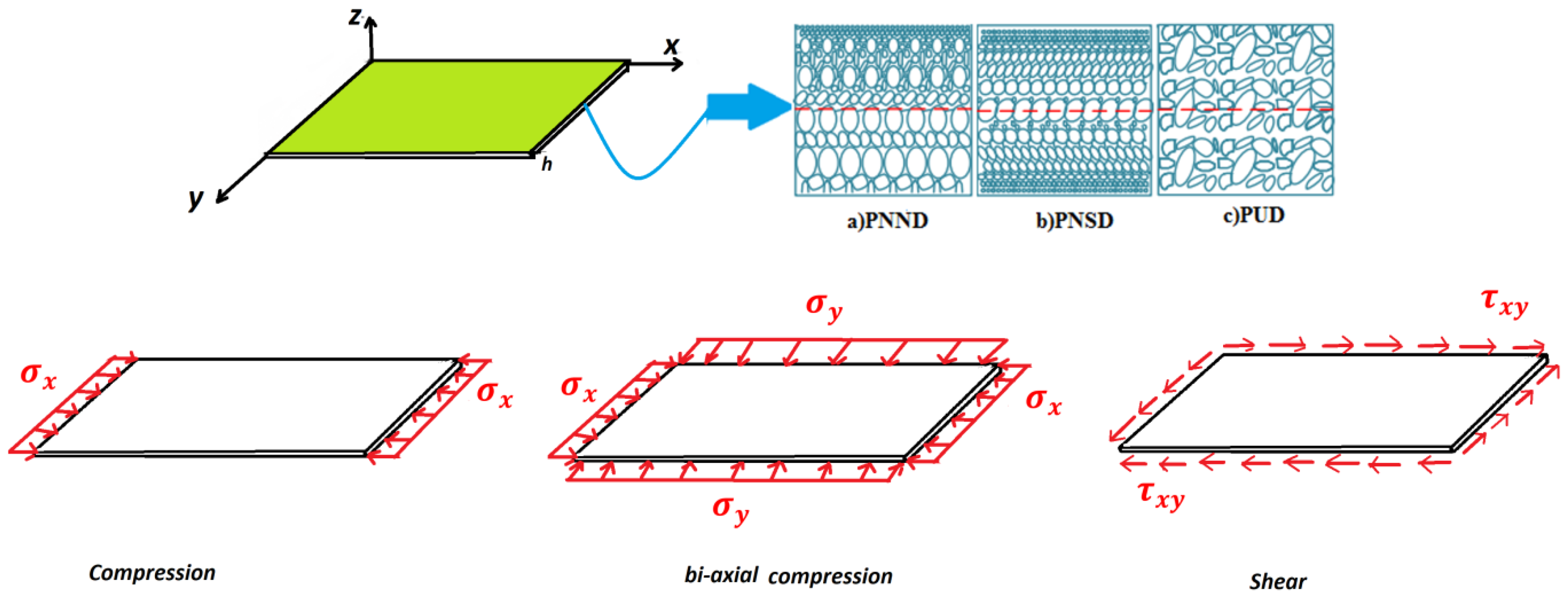
2.1. Poroelastic Modeling of Plates

Let us consider a rectangular FG porous plate, with in-plane dimensions a and b , and thickness h , as depicted in Figure 1, along with three different porosity patterns throughout the thickness direction ( 0 z h ) , namely, a non-symmetric nonlinear porous distribution (PNND), a symmetric nonlinear porous distribution (PNSD) and a uniform porous distribution (PUD). Except for uniform porosities, the mechanical properties of the material in terms of shear modulus, Young’s modulus and mass density, for a PNND and PNSD, are defined as in Equation (1) [36,37,38,39,40].
E = E 1 [ 1 e 0 Q ] G = G 1 [ 1 e 0 Q ] ρ = ρ 1 [ 1 e m Q ]
In which
Q ( z ) = { ( a ) P N N D c o s ( π z 2 h ) ( b ) PNSD     c o s ( π 2 π z h )
and 0 e 0 1 is the porosity coefficient. Moreover, E 1 , G 1 and ρ 1 denote the Young’s modulus, the shear modulus and the mass density at z = h (for a PNND) and at z = 0 (for a PNSD), whereby E j = 2 G j ( 1 + ν ) , j = 0 , 1 and the Poisson’s ratio, ν , is assumed to be constant in the z-direction. The constitutive equations of FG-saturated porous rectangular plates are derived from Biot’s theory, which accounts for the displacements field of the solid, the pore fluid movement as well as their interactions owing to the applied loads [41]. Based on Biot’s theory, the constitutive law is thus written as [42]:
σ i j = 2 G ε i j + λ ε k k δ i j p α δ i j
where
p = M ¯ ( Ψ α ε k k ) M ¯ = 2 G ( v u v ) α 2 ( 1 2 v u ) ( 1 2 v ) v u = v + α β ( 1 2 v ) / 3 1 α β ( 1 2 v ) / 3 v = ε j j ε i i | σ i i = 0 , p = 0 , i j v u = ε j j ε i i | σ i i = 0 , Ψ = 0 , i j α = 1 K K S K = 2 ( 1 + v ) 3 ( 1 2 v ) G K u = 2 ( 1 + v u ) 3 ( 1 2 v u ) G
Note that p is the pore fluid pressure, such that, for p = 0 , Biot’s law reverts to the classical Hooke’s law (or drained condition). In addition, λ denotes the Lamè constant, δ i j is the Kronecker delta and α is the Biot’s effective stress coefficient (with 0 < α < 1 ). This parameter accounts for the effect of porosity on the structural behavior and resistance of porous materials in the absence of an internal fluid. At the same time, M ¯ , G , ν u , ε k k , Ψ , K s and β stand for the Biot’s modulus, shear modulus, undrained Poisson’s ratio ( ν < ν u < 0.5 ) , volumetric strain, variation of fluid volume content, bulk modulus of a homogeneous material and the Skempton coefficient, which introduces the pore fluid property, respectively. This last coefficient, β , in particular, denotes a dimensionless parameter to include the impact of a fluid within cavities on the overall response of a porous material in undrained condition ( Ψ = 0 ), and it is described as the ratio of the cavity pressure to the total body stress, namely,
β = d p d σ | Ψ = 0 = 1 1 + e 0 C P C S = K u K α K u
In which K u , K refer to the bulk modulus in undrained and drained conditions respectively, and C P and C S stand for the fluid and solid compressibility in pores. Thus, the Skempton coefficient defines the effect of fluid compressibility on the elastic modulus and compressibility of the whole porous material [42].

2.2. Governing Equations

The governing equations of the problem are derived here from the principle of virtual work, as follows:
δ U δ V g = 0
where U is the total strain potential energy of the plate defined on the domain Ω as:
U = 1 2 Ω σ i j ε i j d Ω
and V g is the potential energy related to geometry, which takes the following form:
V g = 1 2 Ω { P x [ ( u x ) 2 + ( w x ) 2 + ( v x ) 2 ] + P y [ ( u y ) 2 + ( w y ) 2 + ( v y ) 2 ] + P x y ( w x w y + v x v y u x u y ) } d Ω
By substitution of Equations (6) and (7) into Equation (5), the following relation is obtained:
0 h 0 a 0 b [ ( σ x x δ ε x x + σ y y δ ε y y + σ z z δ ε z z + σ y z δ γ y z + σ x z δ γ x z + σ x y δ γ x y ) P x ( u x δ u x + v x δ v x + w x δ w x ) P y ( u y δ u y + v y δ v y + w y δ w y ) P x y ( δ w x w y + δ w y w x + δ v x v y + δ v y v x δ u x u y δ u y u x ) ] d v = 0
where the constitutive relations for FG-saturated porous plates in 3D poroelasticity can be defined according to Biot’s constitutive law, as [ σ i j ] = [ C ] [ ε i j ] . For FG-saturated porous rectangular plates, the elasticity matrix reads as follows:
C = E ( 1 ν ) ( 1 + ν ) ( 1 2 ν ) ( 1 ν 1 ν ν 1 ν 0 0 0 ν 1 ν 1 ν 1 ν 0 0 0 ν 1 ν ν 1 ν 1 0 0 0 0 0 0 1 2 ν 2 ( 1 ν ) 0 0 0 0 0 0 1 2 ν 2 ( 1 ν ) 0 0 0 0 0 0 1 2 ν 2 ( 1 ν ) ) + ( M ¯ α 2 0 0 0 0 0 0 M ¯ α 2 0 0 0 0 0 0 M ¯ α 2 0 0 0 0 0 0 0 0 0 0 0 0 0 0 0 0 0 0 0 0 0 ) = = E   Λ + ϒ = [ C 11 C 12 C 12 0 0 0 C 12 C 11 C 12 0 0 0 C 12 C 12 C 11 0 0 0 0 0 0 C 44 0 0 0 0 0 0 C 55 0 0 0 0 0 0 C 66 ]
The elasticity modulus, E, is assumed to vary along the z-direction, whereas the Poisson’s ratio, ν , remains constant.

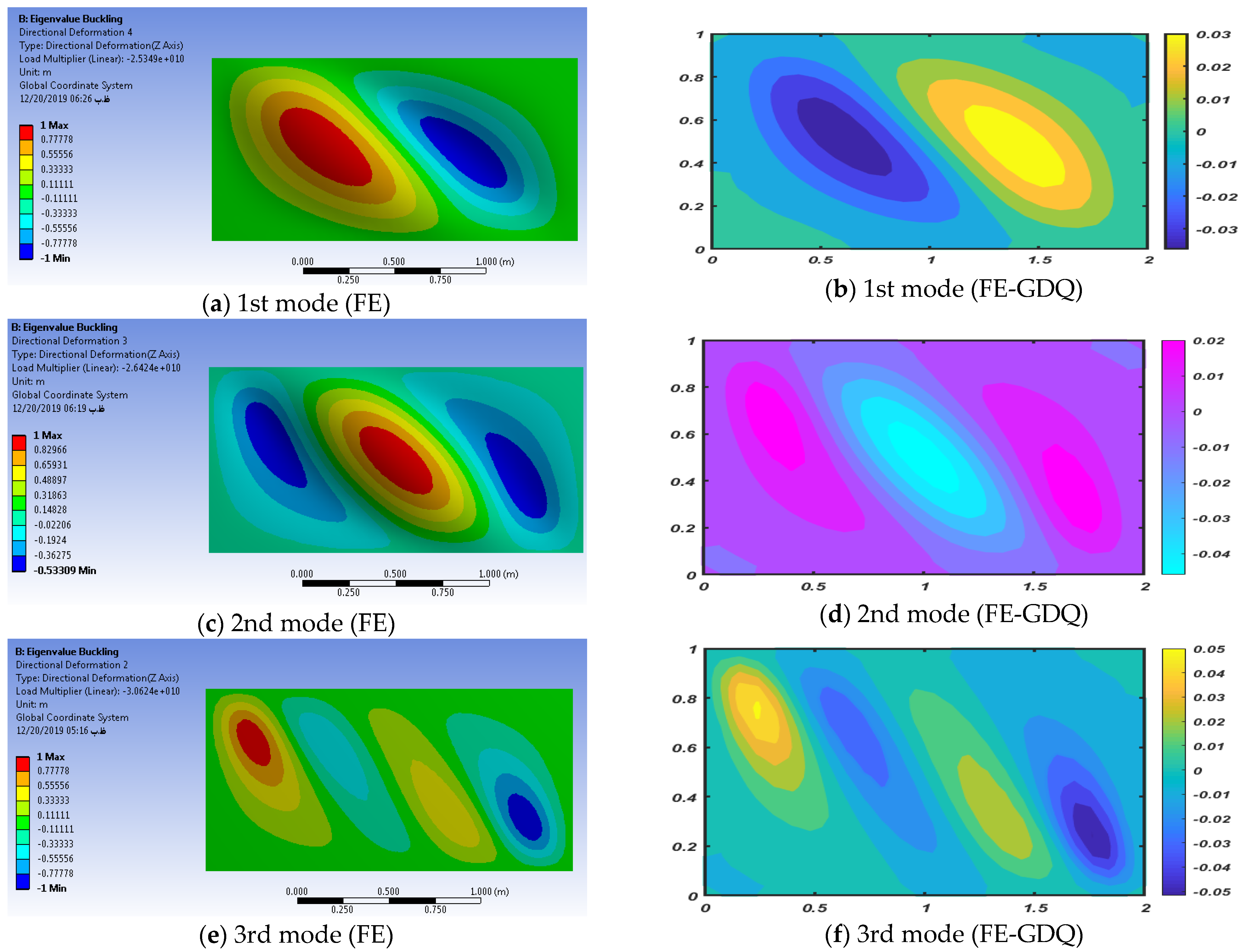
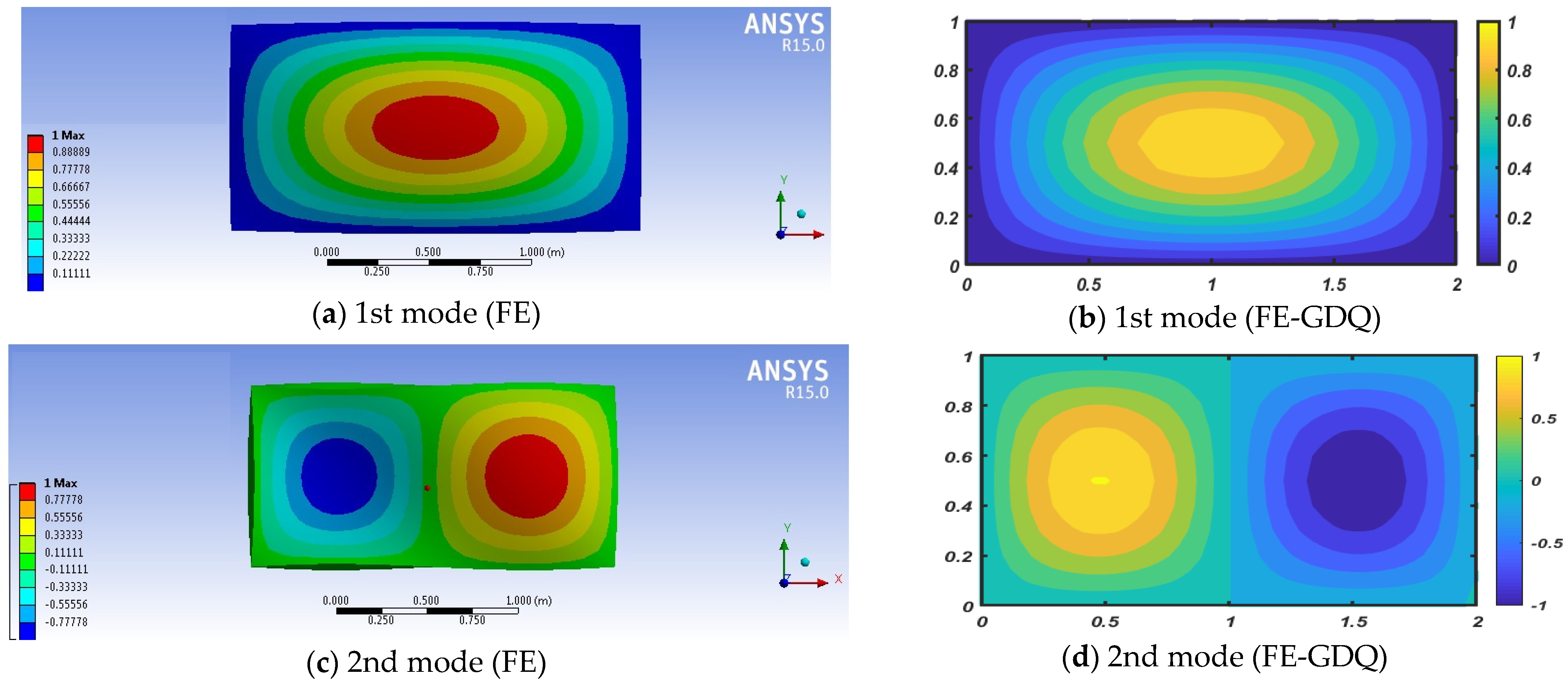
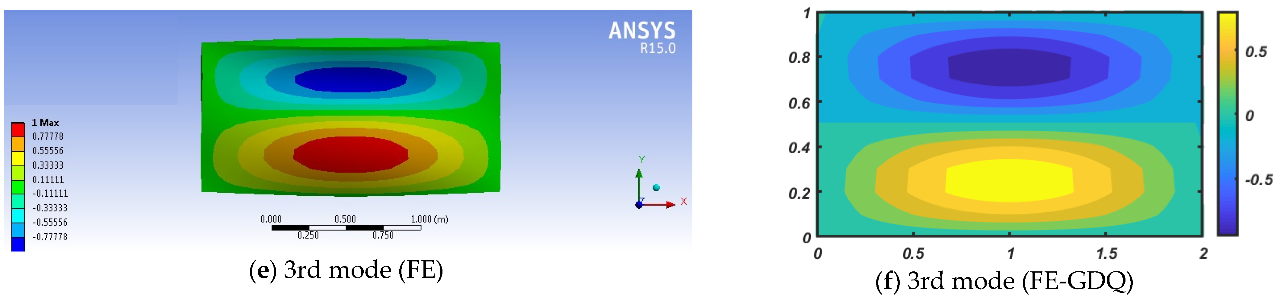
3. Mixed FE-GDQ Numerical Formulation

A set of rectangular-quadratic elements, N e , is considered to discretize the x–y plane of the domain. Each element should be differentiable at both in-plane and transverse displacements for solving the governing equations. Hence, the displacement components are approximated as:
u ( x , y , z , t ) = j = 1 N φ j ( x , y ) U j ( z , t ) ,   v ( x , y , z , t ) = j = 1 N φ j ( x , y ) V j ( z , t ) , j = 1 , 2 , , N     w ( x , y , z , t ) = j = 1 N φ j ( x , y ) W j ( z , t )
where N stands for the total number of nodes in the discretized x–y plane, and φ j ( x , y ) denotes the global Lagrange interpolation functions. By combination of Equations (3) and (8), and integrating by parts in the z-direction, the following governing equations per each node i ( i = 1 , 2 , , N ) are obtained:
δ U i : j = 1 N A i j C 55 ( z j ) 2 U j z 2 + j = 1 N C 55 ( z j ) z U j z + j = 1 N ( D i j C 55 ( z j ) D j i C 12 ( z j ) ) W j z + j = 1 N C 44 z ( z j ) W j j = 1 N ( E j i C 12 ( z j ) + E i j C 66 ( z j ) ) U j j = 1 N ( F i j C 11 ( z j ) + H j i C 66 ( z j ) ) V j P x j = 1 N D b i j V j P y j = 1 N B b i j V j P x y j = 1 N S b i j V j P x y j = 1 N K b i j V j = 0
δ V i : j = 1 N A i j C 44 ( z j ) 2 V j z 2 + j = 1 N C 44 ( z j ) z V j z + j = 1 N ( D i j C 44 ( z j ) D j i C 12 ( z j ) ) W j z + j = 1 N C 44 z ( z j ) W j j = 1 N ( E j i C 12 ( z j ) + E i j C 66 ( z j ) ) U j j = 1 N ( F i j C 11 ( z j ) + H j i C 66 ( z j ) ) V j P x j = 1 N D b i j V j P y j = 1 N B b i j V j P x y j = 1 N S b i j V j P x y j = 1 N K b i j V j = 0
δ W i : j = 1 N A i j C 11 ( z j ) 2 W j z 2 + j = 1 N ( B i j C 12 ( z j ) B i j C 55 ( z j ) ) U j z + j = 1 N ( D i j C 12 ( z j ) D j i C 44 ( z j ) ) V j z j = 1 N B i j C 12 ( z ) z U j + j = 1 N D i j C 12 ( z ) z V j + j = 1 N ( F i j C 44 ( z j ) + H i j C 55 ( z j ) + A i j C 11 ( z ) z ) W j P x j = 1 N D b i j W j P y j = 1 N B b i j W j P x y j = 1 N S b i j W j P x y j = 1 N K b i j W j = 0
where,
H i j = 0 a 0 b φ i x φ j x d x d y , F i j = 0 a 0 b φ i y φ j y d x d y , E i j = 0 a 0 b φ i x φ j y d x d y H i j = 0 a 0 b φ i x φ j x d x d y , F i j = 0 a 0 b φ i y φ j y d x d y , E i j = 0 a 0 b φ i x φ j y d x d y D b i j = 0 a 0 b φ i x φ j x d y d x , B b i j = 0 a 0 b φ i y φ j y d y d x , S b i j = 0 a 0 b φ i x φ j y d y d x , K b i j = 0 a 0 b φ i y φ j x d y d x
The BCs at the lower and upper surfaces ( z = 0 and z = h ) associated with Equations (11)–(13) are defined as:
Either     δ U i = 0 , or { j = 1 N A i j C 55 ( z j ) U j z + j = 1 N B i j C 55 ( z i j ) W j = 0     at   z = 0 , j = 1 N A i j C 55 ( z j ) U j z + j = 1 N B i j C 55 ( z i j ) W j = 0       at   z = h ,
Either δ V i = 0 , or { j = 1 N A i j C 44 ( z j ) V j z + j = 1 N D i j C 44 ( z j ) W j = 0 at z = 0 , j = 1 N A i j C 44 ( z j ) V j z + j = 1 N D i j C 44 ( z j ) W j = 0 at z = h ,
Either δ W i = 0 , or { j = 1 N A i j C 11 ( z j ) W j z + j = 1 N D i j C 12 ( z j ) V j + j = 1 N B i j C 12 ( z j ) U j = 0 at z = 0 j = 1 N A i j C 11 ( z j ) W j z + j = 1 N D i j C 12 ( z j ) V j + j = 1 N B i j C 12 ( z j ) U j = 0 at z = h
As far as the GDQ method is concerned, this approach discretizes the spatial derivatives of a function f ( z , t ) as a weighted linear sum of the functional values at all nodes in the solution domain, by means of some fixed weighting coefficients. Thus, the first- and second-order derivatives of a one-dimensional function read as follows:
f ( z , t ) z | z = z i = j = 1 N z A i j z f ( z j , t ) = j = 1 N z A i j z f j ( t ) 2 f ( z , t ) z 2 | z = z i = j = 1 N z B i j z f ( z j , t ) = j = 1 N z B i j z f j ( t )
where A i j z and B i j z are the weighted coefficients at the grid nodes of the solution domain. To derive the weighting coefficients, the following relations are employed:
A i j z = { M ( z i ) ( z i z j ) M ( z i ) for i j k = 1 , k i N z A i k z for i = j i , j = 1 , 2 , , N z ,
B i j z = { 2 [ A i i z A i j z A i j z z i z j ] for i j , k = 1 , k i N z B i k z for i = j i , j = 1 , 2 , , N z ,
being
M ( 1 ) ( z i ) = j = 1 , j i N ( z i z j )   for i = 1 , 2 , , N
To obtain more accurate results, a Chebyshev–Gauss–Lobatto quadrature-mesh size is assumed here, in line with findings by Malik and Bert [43]. At the current stage, the GDQ method is employed to discretize the system of equations through the thickness direction (i.e., along the z-axis). A set of N z grid points is assumed to discretize the domain along the thickness direction for each quadratic grid point. This means that Equations (11)–(13) can be rewritten in the domain (i.e., for each node k = 2 , 3 , , N z 1 ), as follows:
δ U i : j = 1 N m = 1 N z A i j C 55 ( z j ) B k m U j m + j = 1 N C 55 ( z j ) z A k m z U j m + j = 1 N m = 1 N Z ( B i j C 55 ( z j ) B i j C 12 ( z j ) ) A k m z W j m + j = 1 N C 44 z ( z j ) W j j = 1 N ( E j i C 12 ( z j ) + E i j C 66 ( z j ) ) U j j = 1 N ( F i j C 11 ( z j ) + H j i C 66 ( z j ) ) V j P x j = 1 N D b i j V j P y j = 1 N B b i j V j P x y j = 1 N S b i j V j P x y j = 1 N K b i j V j = 0
δ V i : j = 1 N m = 1 N Z A i j C 44 ( z j ) B k m V j m + j = 1 N m = 1 N Z C 44 ( z j ) z A k m z V k m + j = 1 N m = 1 N Z ( D i j C 44 ( z j ) D j i C 12 ( z j ) ) A k m z W k m + j = 1 N C 44 z ( z j ) W j j = 1 N ( E j i C 12 ( z j ) + E i j C 66 ( z j ) ) U j j = 1 N ( F i j C 11 ( z j ) + H j i C 66 ( z j ) ) V j P x j = 1 N D b i j V j P y j = 1 N B b i j V j P x y j = 1 N S b i j V j P x y j = 1 N K b i j V j = 0
δ W i : j = 1 N m = 1 N Z A i j C 11 ( z j ) B k m z W j m + j = 1 N m = 1 N Z ( B i j C 12 ( z j ) B i j C 55 ( z j ) ) A k m z U j m + j = 1 N m = 1 N z ( D i j C 12 ( z j ) D j i C 44 ( z j ) ) A k m z V j m j = 1 N B i j C 12 ( z ) z U j + j = 1 N D i j C 12 ( z ) z V j + j = 1 N ( F i j C 44 ( z j ) + H i j C 55 ( z j ) + A i j C 11 ( z ) z ) W j P x j = 1 N D b i j W j P y j = 1 N B b i j W j P x y j = 1 N S b i j W j P x y j = 1 N K b i j W j = 0
Likewise, the BCs in Equations (15)–(17) at the top and bottom sides of the structures take the following form:
Either U i k = 0 , or { j = 1 N m = 1 N z A i j C 55 ( z j ) A k m z U j m + j = 1 N B i j C 55 ( z j ) W j k = 0 for k = 1 j = 1 N m = 1 N z A i j C 55 ( z j ) A k m z U j m + j = 1 N B i j C 55 ( z j ) W j k = 0 for k = N Z
Either V i k = 0 , or { j = 1 N m = 1 N z A i j C 44 ( z j ) A k m z V j m + j = 1 N D i j C 44 ( z j ) W j k = 0 for k = 1 j = 1 N m = 1 N z A i j C 44 ( z j ) A k m z V j m + j = 1 N D i j C 44 ( z j ) W j k = 0 for k = N Z
Either W i k = 0 , or { j = 1 N m = 1 N z A i j C 11 ( z j ) A k m z W j m + j = 1 N D i j C 12 ( z j ) V j k + j = 1 N B i j C 12 ( z j ) U j k = 0 , for k = 1 j = 1 N m = 1 N z A i j C 11 ( z j ) A k m z W j m + j = 1 N D i j C 12 ( z j ) V j k + j = 1 N B i j C 12 ( z j ) U j k = 0 , for k = N Z
For a unified treatment of the problem, the degrees of freedom (DOFs) can be divided into the domain- and boundary-type DOFs, as follows:
U d = { U 12 U 13 U N ( N z 1 ) } , V d = { V 12 V 13 V N ( N z 1 ) } , W d = { W 12 W 13 W N ( N z 1 ) } , U b = { U 11 U 21 U N N z } , V b = { V 11 V 21 V N N z } , W b = { W 11 W 21 W N N z } ,
In which W m n = W m ( z n , t ) , V m n = V m ( z n , t ) , U m n = U m ( z n , t ) .
This means that Equations (21)–(23) can be rearranged in matrix form as:
[ k b b k b d k d b k d d ] [ d b d d ] = P [ 0 0 0 G ] [ d b d d ]
where the stiffness quantities k b b ,   k d b ,   k b d ,   k d d refer to the boundary, b , and domain, d , weighting coefficients of the plate respectively, [ d b d d ] T is the displacement vector, P refers to the buckling load and G is the stability matrix due to the in-plane stresses.
At the same time, from Equations (23)–(26), the boundary weight coefficients can be replaced by the domain weight coefficients as follows:
d b = k b b 1 k b d d d
By substitution of d b from Equation (29) into Equation (28), and considering the harmonic solution [ U d V d W d ] = [ U ¯ d V ¯ d W ¯ d ] e i w t , the governing equations of the problem can be rewritten in terms of the domain unknowns, as follows:
K [ U ¯ d V ¯ d W ¯ d ] P G [ U ¯ d V ¯ d W ¯ d ] = 0
where K is the stiffness matrix, defined as:
K = K d d K d b K b b 1 K b d
The solution of Equation (30) corresponds to the critical buckling load of the structure under in-plane conditions, labeled hereafter as λ .
In what follows, three different BCs for the buckling analysis of the plate structure are considered:
(i)
Simply supported BCs at all edges (SSSS):
w ( 0 , y , z ) = w ( a , y , z ) = w ( x , 0 , z ) = w ( x , b , z ) = 0 u ( 0 , y , z ) = u ( a , y , z ) = v ( x , 0 , z ) = v ( x , b , z ) = 0
(ii)
Clamped BCs at edges parallel to the y-axis (i.e., at x = 0 , a ) and free BCs at edges parallel to the x-axis (i.e., at y = 0 , b ) (CFCF):
u , v , w ( 0 , y , z ) = u , v , w ( a , y , z ) = 0
(iii)
Clamped BCs at edges parallel to the x-axis (i.e., at y = 0 , b ) and free BCs at edges parallel to the y-axis (i.e., at x = 0 , a ) (FCFC):
u , v , w ( x , 0 , z ) = u , v , w ( x , b , z ) = 0
Note that the (i)-type BC is considered for both uniaxial and biaxial loading conditions.

4. Numerical Investigation

The numerical study starts with a preliminary validation of the proposed formulation against the classical FE results (Ansys Workbench). At the present stage, the porosity coefficient is assumed to be zero ( e 0 = 0 ) , together with a null Skempton coefficient, a null Biot’s modulus M ¯ = 0 , a null pore fluid pressure p = 0 and ν u = ν = 1 / 3 , E 1 = 210   GPa . The rectangular plate selected here for the analysis has b = 1   m ,   a / b = 2 and h = 0.1   m . Table 1 summarizes the results for the first three buckling loads ( λ 1 , λ 2 , λ 3 ) , as provided by our proposed FE-GDQ formulation and FEs, while considering the three different BCs (32)–(34) alternatively, as well as a uniaxial or biaxial loading condition. To model the problem in Ansys Workbench, the most accurate 20-node hexahedral quadratic elements were chosen to mesh the plate. First, a linear static analysis for edge loads equal to 1 Pa was performed in a static structural environment, and then the solutions were transferred to an eigenvalue buckling environment. Based on the results from this table, the good correspondence among predictions from the two alternative computational strategies proves the reliability and accuracy of the proposed FE-GDQ method to handle the problem. This is also confirmed in terms of mode shapes, as visible in the contour plots of Figure 2 and Figure 3, at least for the SSSS rectangular plate under a shear and biaxial loading, respectively.
After this validation step, the numerical study aimed at computing the buckling load of FG-saturated porous plates in undrained conditions, accounting for the effects of different BCs, aspect ratios, Skempton coefficients, porosity distributions and porosity coefficients, while keeping the geometry and material properties of the structure fixed. In Table 2, Table 3 and Table 4, the first four shear buckling loads are summarized for a FG-saturated plate under the SSSS, FCFC and CFCF BCs respectively, while keeping the Skempton coefficient constant. The systematic study starts by considering a square plate with aspect ratio a / b = 1 , thus extending the analysis to a rectangular plate with a / b = 2 . In each case, the porosity coefficient, e 0 , is gradually increased from 0.3 up to 0.6, by steps of 0.3, to check for the sensitivity of the buckling response to porosity. As expected, when the porosity coefficient increases, the stiffness of the structure decreases, and the buckling load decreases as well. The results demonstrate that the maximum and minimum values of the buckling load are associated with the symmetric (PNSD) and uniform (PUD) porosity distributions respectively, due to the highest and lowest stiffness reached in the structure. An intermediate buckling load level, instead, is always obtained for a PNND porosity distribution within the material. It also seems that the effect of the porosity coefficient, e 0 , on the buckling load becomes more pronounced for a uniform porosity distribution than the other ones. Moreover, by increasing the aspect ratio a / b , the buckling load can decrease or increase, under the same assumptions of porosity coefficient and distribution, depending on the selected BC. Differently from the FCFC case, a clear reduction of the buckling load is noticed for a SSSS and CFCF porous plate with an increased aspect ratio. This confirms the strict dependence of the stiffness on the geometrical dimensions and BCs of the structural member.
The same parametric investigation was then repeated for a biaxial loading (Table 5) and a uniaxial loading acting in the x-direction of a SSSS structure (Table 6). Based on a comparative evaluation of results in Table 5 and Table 6 with Table 2, a uniaxial or biaxial loading condition clearly reduces the buckling load of the structure under the same values of e 0 , a / b and porosity distribution.
As expected, this reduction is much more pronounced for rectangular plates subjected to a biaxial loading condition, due to the overall decay of the structural stiffness. A further investigation considered the effect of the porosity distribution and Skempton coefficient on the first four buckling loads of FG-saturated plates, as listed in Table 7, Table 8 and Table 9 (for a shear loading condition), in Table 10 (for an axial loading condition) and in Table 11 (for a biaxial loading condition), while keeping the porosity coefficient fixed at e 0 = 0.6 . The same BCs from Table 1 are accounted here for the analyses. Based on a comparative estimation of results from these tables, it is confirmed that the maximum and minimum buckling loads are always associated with a symmetric (PNSD) and uniform (PUD) porosity distribution, respectively.
Results denote that in drained conditions (i.e., β = 0 ), the plate always features the smallest buckling load, under a fixed aspect ratio, porosity coefficient and distribution. An increasing value of the Skempton coefficient, instead, enables an increased buckling load, because of a decreased compressibility of the fluid within pores. In other words, if the compressibility of the pore fluid becomes high ( β 0 ), the mechanical response of the plate resembles that of a porous plate in drained conditions (i.e., in the absence of fluid). In this condition, the structural stiffness reaches its minimum value along with the lowest buckling load. Differently, when the compressibility of a pore fluid becomes small ( β 1 ), the plate behaves as a rigid solid, thus reaching its highest load magnitude. Furthermore, the effect of the Skempton coefficient on the buckling load, for a uniform distribution, seems to be more pronounced than other porosity distributions. By comparing Table 2, Table 3, Table 4, Table 5 and Table 6 with Table 7, Table 8, Table 9, Table 10 and Table 11, it is worth observing the higher sensitivity of the buckling response to the porosity coefficient than the Skempton coefficient. The first four buckling mode shapes are finally plotted in Figure 4, Figure 5, Figure 6, Figure 7 and Figure 8, for a rectangular plate with a = 2 m , b = 1 m , under different loading and boundary conditions, and a fixed value of e 0 = β = 0.6 . More specifically, in Figure 4, Figure 5 and Figure 6, the rectangular plate is subjected to a shear loading condition, with a clear compatibility among the displacement field and the selected BCs (i.e., CFCF, FCFC and SSSS, respectively). Figure 7 and Figure 8 plot the four mode shapes for the same plate under a uniaxial (Figure 7) and biaxial (Figure 8) loading, where the kinematic response clearly changes depending on the selected loading condition.

5. Conclusions

The present work focused on the buckling behavior of FG-saturated porous rectangular plates subjected to normal and shear loads, while adopting Biot’s constitutive law and proposing a combined FE-GDQ as an efficient computational tool to solve the problem. This means that the in-plane problem has been discretized in the x–y-directions by means of classical FEs, and follows a weak formulation. Along the thickness direction (the z-direction), instead, the problem is defined in a strong form based on a GDQ approximation. This mixed method deals with a three-dimensional theory of elasticity without any additional kinematic assumption for the plate deformability. Various numerical examples have been considered and solved systematically to check for the reliability of the proposed method against a pure FE response, as well as to study the sensitivity of the response to some input parameters, i.e., the geometrical aspect ratio, the Skempton coefficients, the porosity distribution and coefficient and the BCs. Based on the parametric analysis, the main conclusions can be summarized as follows:
  • The porosity coefficient more significantly affects the buckling load than the Skempton coefficient. In detail, an increased porosity coefficient and a decreased Skempton coefficient yield an overall decrease of the buckling load.
  • Among different boundary and loading conditions, the maximum and minimum values of the buckling load are reached for a FCFC plate under a shear loading and a SSSS plate under a biaxial loading condition, respectively.
  • The influence of the porosity coefficient on the buckling load for a uniform distribution is larger than other types of non-uniform porosity distributions.
  • The effect of the Skempton coefficient on the buckling load, for a uniform distribution, is larger than other types of porosity distributions.
  • By increasing the ratio, the buckling load generally decreases, except for a FCFC plate under a shear load and a SSSS plate under a normal uniaxial load, because of the variability in stiffness of the overall structure.
  • The proposed method is verified to be a reliable tool for the computational study of saturated porous materials and structures, even from a design standpoint.

Author Contributions

Conceptualization, F.T.; Data curation, F.T.; Formal analysis, F.K., M.B., K.A., R.D. and F.T.; Investigation, F.K., M.B., K.A., R.D. and F.T.; Methodology, R.D. and F.T.; Supervision, R.D. and F.T.; Validation, R.D. and F.T.; Writing—original draft, F.K., M.B. and K.A.; Writing—review & editing, R.D. and F.T. All authors have read and agreed to the published version of the manuscript.

Funding

This research received no external funding.

Conflicts of Interest

The authors declare no conflict of interest.

Nomenclature

Fluid compressibility in pores C P
Solid compressibility in pores C s
Shear modulus G
Porosity coefficient e0
Biot’s effective stress coefficient α
Skempton coefficient β
Variation of fluid volume content Ψ
Volumetric strain ε k k
Poisson’s ratio ν
Undrained Poisson’s ratio ν u
Lamè constant λ
Pore fluid pressureP
Bulk modules K
Undrained bulk modules Ku
Biot’s modulus M ¯
Total strain potential energy U
Potential energy related to geometry V g
Elasticity modulusE
Stress tensor [ σ i j ]
Strain tensor [ ε i j ]
Elasticity matrix [ C ]
Displacement components along x, y and z directionsu, v, w
Global Lagrange interpolation functions φ j ( x , y )
Weighted coefficients at the grid nodes of the solution domain A i j z , B i j z
Buckling loadλ
Stability matrix due to the in-plane stresses G
Stiffness matrix K

References

  1. Biot, M.A. Theory of buckling of a porous slab and its thermoelastic analogy. J. Appl. Mech. ASME 1964, 31, 94–198. [Google Scholar] [CrossRef]
  2. Magnucki, K.; Stasiewicz, P. Elastic buckling of a porous beam. J. Theor. Appl. Mech. 2004, 42, 859–868. [Google Scholar]
  3. Magnucka-Blandzi, E. Axi-symmetrical deflection and buckling of circular porous-cellular plate. Thin-Walled Struct. 2008, 46, 333–337. [Google Scholar] [CrossRef]
  4. Magnucki, K.; Malinowski, M.; Kasprzak, J. Bending and buckling of a rectangular porous plate. Steel Compos. Struct. 2006, 6, 319–333. [Google Scholar] [CrossRef]
  5. Chen, D.; Yang, J.; Kitipornchai, S. Elastic buckling and static bending of shear deformable functionally graded porous beam. Compos. Struct. 2015, 133, 54–61. [Google Scholar] [CrossRef] [Green Version]
  6. Jasion, P.; Magnucka-Blandzi, E.; Szyc, W.; Magnucki, K. Global and local buckling of sandwich circular and beam-rectangular plates with metal foam core. Thin-Walled Struct. 2012, 61, 154–161. [Google Scholar] [CrossRef]
  7. Gao, K.; Huang, Q.; Kitipornchai, S.; Yang, J. Nonlinear dynamic buckling of functionally graded porous beams. Mech. Adv. Mater. Struct. 2019, 28, 418–429. [Google Scholar] [CrossRef]
  8. Tang, H.; Li, L.; Hu, Y. Buckling analysis of two-directionally porous beam. Aerosp. Sci. Techn. 2018, 78, 471–479. [Google Scholar] [CrossRef]
  9. Ebrahimi, F.; Jafari, A. Buckling behavior of smart MEE-FG porous plate with various boundary conditions based on refined theory. Adv. Mater. Res. 2016, 5, 279–298. [Google Scholar] [CrossRef] [Green Version]
  10. Kumar, R.; Lal, A.; Singh, B.N.; Singh, J. Meshfree approach on buckling and free vibration analysis of porous FGM plate with proposed IHHSDT resting on the foundation. Curved Layer. Struct. 2019, 6, 192–211. [Google Scholar] [CrossRef]
  11. Cong, P.H.; Chien, T.M.; Khoa, N.D.; Duc, N.D. Nonlinear thermomechanical buckling and post-buckling response of porous FGM plates using Reddy’s HSDT. Aerosp. Sci. Technol. 2018, 77, 419–428. [Google Scholar] [CrossRef]
  12. Bourada, M.; Bouadi, A.; Bousahla, A.A.; Senouci, A.; Bourada, F.; Tounsi, A.; Mahmoud, S.R. Buckling behavior of rectangular plates under uniaxial and biaxial compression. Struct. Eng. Mech. 2019, 70, 113–123. [Google Scholar]
  13. Thang, P.T.; Nguyen-Thoi, T.; Lee, D.; Kang, J.; Lee, J. Elastic buckling and free vibration analyses of porous-cellular plates with uniform and non-uniform porosity distributions. Aerosp. Sci. Techn. 2018, 79, 278–287. [Google Scholar] [CrossRef]
  14. Chen, D.; Yang, J.; Kitipornchai, S. Buckling and bending analyses of a novel functionally graded porous plate using Chebyshev-Ritz method. Arch. Civ. Mech. Eng. 2019, 19, 157–170. [Google Scholar] [CrossRef]
  15. Yang, J.; Chen, D.; Kitipornchai, S. Buckling and free vibration analyses of functionally graded graphene reinforced porous nanocomposite plates based on Chebyshev-Ritz method. Compos. Struct. 2018, 193, 281–294. [Google Scholar] [CrossRef]
  16. Tu, T.M.; Hoa, L.K.; Hung, D.X.; Hai, L.T. Nonlinear buckling and post-buckling analysis of imperfect porous plates under mechanical loads. J. Sandw. Struct. Mater. 2018, 22, 1910–1930. [Google Scholar] [CrossRef]
  17. Sekkal, M.; Fahsi, B.; Tounsi, A.; Mahmoud, S.R. A new quasi-3D HSDT for buckling and vibration of FG plate. Struct. Eng. Mech. 2017, 64, 737–749. [Google Scholar]
  18. Shahsavari, D.; Karami, B.; Fahham, H.R.; Li, L. On the shear buckling of porous nanoplates using a new size-dependent quasi-3D shear deformation theory. Acta Mech. 2018, 229, 4549–4573. [Google Scholar] [CrossRef]
  19. Safaei, B.; Moradi-Dastjerdi, R.; Behdinan, K.; Chu, F. Critical buckling temperature and force in porous sandwich plates with CNT-reinforced nanocomposite layers. Aerosp. Sci. Techn. 2019, 91, 175–185. [Google Scholar] [CrossRef]
  20. Li, Q.; Wu, D.; Chen, X.; Liu, L.; Yu, Y.; Gao, W. Nonlinear vibration and dynamic buckling analyses of sandwich functionally graded porous plate with graphene platelet reinforcement resting on Winkler–Pasternak elastic foundation. Int. J. Mech. Sci. 2018, 148, 596–610. [Google Scholar] [CrossRef]
  21. Shahgholian, D.; Safarpour, M.; Rahimi, A.R.; Aligeigloo, A. Buckling analyses of functionally graded graphene-reinforced porous cylindrical shell using the Rayleigh–Ritz method. Acta Mech. 2020, 231, 1887–1902. [Google Scholar] [CrossRef]
  22. Zhao, S.; Yang, Z.; Kitipornchai, S.; Yang, J. Dynamic instability of functionally graded porous arches reinforced by graphene platelets. Thin-Walled Struct. 2020, 147, 106491. [Google Scholar] [CrossRef]
  23. Jabbari, M.; Rezaei, M.; Mojahedin, A.; Eslami, M. Mechanical buckling of FG saturated porous rectangular plate under temperature field. Iranian J. Mech. Eng. Tran. ISME 2016, 17, 61–78. [Google Scholar]
  24. Jabbari, M.; Rezaei, M.; Mojahedin, A. Mechanical buckling of FG saturated porous rectangular plate with piezoelectric actuators. Iranian J. Mech. Eng. Tran. ISME 2016, 17, 46–66. [Google Scholar]
  25. Mojahedin, A.; Jabbari, M.; Salavati, M. Axisymmetric buckling of saturated circular porous-cellular plate based on first-order shear deformation theory. Int. J. Hydromech. 2019, 2, 144–158. [Google Scholar] [CrossRef]
  26. Jabbari, M.; Mojahedin, A.; Khorshidvand, A.R.; Eslami, M.R. Buckling analysis of functionally graded thin circular plate made of saturated porous materials. ASCE J. Eng. Mech. 2014, 34, 287–295. [Google Scholar] [CrossRef]
  27. Jabbari, M.; Hashemitaheri, M.; Mojahedin, A.; Eslami, M.R. Thermal buckling analysis of functionally graded thin circular plate made of saturated porous materials. J. Therm. Stresses 2014, 37, 202–220. [Google Scholar] [CrossRef]
  28. Jabbari, M.; Mojahedin, A.; Haghi, M. Buckling analysis of thin circular FG plates made of saturated porous-soft ferromagnetic materials in transverse magnetic field. Thin-Walled Struct. 2014, 85, 50–56. [Google Scholar] [CrossRef]
  29. Khorshidvand, A.R.; Joubaneh, E.F.; Jabbari, M.; Eslami, M.R. Buckling analysis of a porous circular plate with piezoelectric sensor–actuator layers under uniform radial compression. Acta Mech. 2014, 225, 179–193. [Google Scholar] [CrossRef]
  30. Feyzi, M.R.; Khorshidvand, A.R. Axisymmetric post-buckling behavior of saturated porous circular plates. Thin-Walled Struct. 2017, 1, 149–158. [Google Scholar] [CrossRef]
  31. Rezaei, A.S.; Saidi, A.R. Buckling response of moderately thick fluid-infiltrated porous annular sector plates. Acta Mech. 2017, 228, 3929–3945. [Google Scholar] [CrossRef]
  32. Anyfantis, K.N. Evaluating the influence of geometric distortions to the buckling capacity of stiffened panels. Thin-Walled Struct. 2014, 140, 450–465. [Google Scholar] [CrossRef]
  33. Shahani, A.R.; Kiarasi, F. Numerical and experimental investigation on post-buckling behavior of stiffened cylindrical shells with cutout subject to uniform axial compression. J. Appl. Comput. Mech. 2021, in press. [Google Scholar] [CrossRef]
  34. Zhang, Y.; Huang, Y.; Meng, F. Ultimate strength of hull structural stiffened plate with pitting corrosion damage under unaxial compression. Mar. Struct. 2017, 56, 117–136. [Google Scholar] [CrossRef]
  35. Kiarasi, F.; Babaei, M.; Dimitri, R.; Tornabene, F. Hygrothermal modeling of the buckling behavior of sandwich plates with nanocomposite face sheets resting on a Pasternak foundation. Contin. Mech. Thermodyn. 2021, 33, 911–932. [Google Scholar] [CrossRef]
  36. Babaei, M.; Hajmohammad, M.H.; Asemi, K. Natural frequency and dynamic analyses of functionally graded saturated porous annular sector plate and cylindrical panel based on 3D elasticity. Aerosp. Sci. Technol. 2020, 96, 105524. [Google Scholar] [CrossRef]
  37. Babaei, M.; Asemi, K.; Safarpour, P. Natural frequency and dynamic analyses of functionally graded saturated porous beam resting on viscoelastic foundation based on higher order beam theory. J. Solid Mech. 2019, 11, 615–634. [Google Scholar]
  38. Babaei, M.; Asemi, K.; Safarpour, P. Buckling and static analyses of functionally graded saturated porous thick beam resting on elastic foundation based on higher order beam theory. Iranian J. Mech. Eng. Tran. ISME 2019, 20, 94–112. [Google Scholar]
  39. Babaei, M.; Asemi, K. Stress analysis of functionally graded saturated porous rotating thick truncated cone. Mech. Based Des. Struct. Mach. 2020, 1–28. [Google Scholar] [CrossRef]
  40. Babaei, M.; Asemi, K.; Kiarasi, F. Static response and free-vibration analysis of a functionally graded annular elliptical sector plate made of saturated porous material based on 3D finite element method. Mech. Based Des. Struct. Mach. 2020, 1–25. [Google Scholar] [CrossRef]
  41. Detournay, E.; Cheng, A.H.D. Fundamentals of poroelasticity. In Analysis and Design Methods; Pergamon: Oxford, UK, 1993; pp. 113–171. [Google Scholar]
  42. Babaei, M.; Asemi, K.; Kiarasi, F. Dynamic analysis of functionally graded rotating thick truncated cone made of saturated porous materials. Thin-Walled Struct. 2021, 164, 107852. [Google Scholar] [CrossRef]
  43. Arshid, E.; Khorshidvand, A.R. Free vibration analysis of saturated porous FG circular plates integrated with piezoelectric actuators via differential quadrature method. Thin-Walled Struct. 2018, 125, 220–233. [Google Scholar] [CrossRef]
Figure 1. Geometrical scheme and loading conditions for a FG-saturated porous plate.
Applsci 11 10434 g001
Figure 2. Comparative evaluation of the first three buckling mode shapes for a SSSS homogenous plate under a shear loading condition.
Applsci 11 10434 g002
Figure 3. Comparative evaluation of the first three buckling mode shapes for a SSSS homogenous plate under a biaxial compression.
Applsci 11 10434 g003aApplsci 11 10434 g003b
Figure 4. First four buckling mode shapes of a FG-saturated porous plate subjected to a shear load (CFCF, a = 2 m, b = 1 m).
Applsci 11 10434 g004
Figure 5. First four buckling mode shapes of a FG-saturated porous plate subjected to a shear load (FCFC, a = 2 m, b = 1 m).
Applsci 11 10434 g005
Figure 6. First four buckling mode shapes of a FG-saturated porous plate subjected to a shear load (SSSS, a = 2 m, b = 1 m).
Applsci 11 10434 g006aApplsci 11 10434 g006b
Figure 7. First four buckling mode shapes of a FG-saturated porous plate subjected to uniaxial load (SSSS, a = 2 m, b = 1 m).
Applsci 11 10434 g007
Figure 8. First four buckling mode shapes of a FG-saturated porous plate subjected to a biaxial load (SSSS, a = 2 m, b = 1 m).
Applsci 11 10434 g008
Table 1. Comparative evaluation of the first three buckling loads (10 GPa), as provided by our formulation and from FEM for different boundary conditions.
FE-GDQ FE Difference (%)
BC λ 1 λ 2 λ 3 λ 1 λ 2 λ 3 λ 1 λ 2 λ 3
Shear loadCFCF0.3140.5290.6240.3170.5740.6780.947.837.96
Shear loadFCFC1.4051.4062.1681.4301.4302.1171.741.672.35
Shear loadSSSS2.5342.6423.0622.5752.6913.06281.591.820
Axial load (x-direction)SSSS1.1971.2312.3811.2061.2402.4010.740.726.7
Biaxial loadSSSS0.2590.4890.7900.2640.4940.7941.891.010.506
Table 2. First four shear buckling loads for a SSSS FG-saturated porous plate with different aspect ratios, a / b , porosity distributions and porosity coefficients, e 0 , keeping β = 0.6 fixed.
Aspect RatioBuckling Load (10 GPa)PNNDPNSDPUD
e 0 = 0.3 e 0 = 0.6 e 0 = 0.9 e 0 = 0.3 e 0 = 0.6 e 0 = 0.9 e 0 = 0.3 e 0 = 0.6 e 0 = 0.9
a/b = 1 λ 1 2.6661.9351.2262.6741.9611.2632.2691.2120.275
λ 2 2.6661.9361.2262.6741.9611.2632.2691.2120.275
λ 3 2.9582.2551.4422.9982.2651.3902.5951.4820.354
λ 4 2.9842.2611.4473.0162.2661.3902.6071.4830.354
a/b = 2 λ 1 2.2811.8631.1622.3922.0051.2692.0831.2810.2952
λ 2 2.3391.8651.1622.4382.0291.2712.1051.2820.2954
λ 3 2.5581.9681.2372.6272.0681.3792.2481.3340.3464
λ 4 2.7192.0441.3072.7612.0941.3882.3501.3560.3467
Table 3. First four shear buckling loads for a FCFC FG-saturated porous plate with different aspect ratios, a / b , porosity distributions and porosity coefficients, e 0 , keeping β = 0.6 fixed.
Aspect RatioBuckling Load (10 GPa)PNNDPNSDPUD
e 0 = 0.3 e 0 = 0.6 e 0 = 0.9 e 0 = 0.3 e 0 = 0.6 e 0 = 0.9 e 0 = 0.3 e 0 = 0.6 e 0 = 0.9
a/b = 1 λ 1 1.1430.8970.5361.1990.9780.6921.0200.6360.177
λ 2 1.1500.9000.5431.2080.9830.6931.0200.6450.182
λ 3 1.6531.2670.7731.7051.3370.8451.4550.8650.219
λ 4 1.6641.2750.7781.7171.3430.8491.4640.8680.219
a/b = 2 λ 1 1.2160.9540.5761.2761.0390.7371.0820.6800.191
λ 2 1.2170.9550.5761.2771.0400.7381.0830.6800.191
λ 3 1.7681.3600.8341.8241.4010.9121.5580.9310.238
λ 4 1.7681.3600.8341.8241.4020.9121.5580.9310.238
Table 4. First four shear buckling loads for a CFCF FG-saturated porous plate with different aspect ratios, a / b , porosity distributions and porosity coefficients, e 0 , keeping β = 0.6 fixed.
Aspect RatioBuckling Load (10 GPa)PNNDPNSDPUD
e 0 = 0.3 e 0 = 0.6 e 0 = 0.9 e 0 = 0.3 e 0 = 0.6 e 0 = 0.9 e 0 = 0.3 e 0 = 0.6 e 0 = 0.9
a/b = 1 λ 1 1.1430.8970.5361.1991.0060.6921.0200.6360.177
λ 2 1.1500.9000.5431.2081.0070.6931.0200.6450.182
λ 3 1.6531.2670.7731.7051.4340.8451.4550.8650.219
λ 4 1.6641.2750.7781.7171.3500.8491.4640.8680.219
a/b = 2 λ 1 0.3100.2550.1530.3300.2920.2410.2870.1860.055
λ 2 0.4970.3930.2290.5380.4700.3750.4490.2810.078
λ 3 0.5980.4660.2810.6100.5200.4050.5280.3250.096
λ 4 0.8050.6220.3740.8170.6820.5040.7080.4300.116
Table 5. First four biaxial buckling loads for a SSSS FG-saturated porous plate with different aspect ratios, a / b , porosity distributions and porosity coefficients, e 0 , keeping β = 0.6 fixed.
Aspect RatioBuckling Load (10 GPa)PNNDPNSDPUD
e 0 = 0.3 e 0 = 0.6 e 0 = 0.9 e 0 = 0.3 e 0 = 0.6 e 0 = 0.9 e 0 = 0.3 e 0 = 0.6 e 0 = 0.9
a/b = 1 λ 1 0.3920.3030.1660.4060.3620.3090.3460.2160.069
λ 2 0.9290.7230.4080.9490.8300.6580.8270.5230.151
λ 3 0.9290.7230.4080.9490.8300.6580.8270.5230.151
λ 4 0.1410.1080.6040.1440.1270.9261.2450.7630.210
a/b = 2 λ 1 0.2330.1860.1060.2400.2210.1930.2090.1380.0420
λ 2 0.4340.3360.1880.4050.4000.3290.3840.2390.0680
λ 3 0.6980.5640.3330.7030.6340.5190.6340.4260.120
λ 4 0.7780.6030.3410.8040.7020.5700.6880.4270.131
Table 6. First four uniaxial buckling loads (in the x-direction) for a SSSS FG-saturated porous plate with different aspect ratios, a / b , porosity distributions and porosity coefficients, e 0 , keeping β = 0.6 fixed.
Aspect RatioBuckling Load (10 GPa)PNNDPNSDPUD
e 0 = 0.3 e 0 = 0.6 e 0 = 0.9 e 0 = 0.3 e 0 = 0.6 e 0 = 0.9 e 0 = 0.3 e 0 = 0.6 e 0 = 0.9
a/b = 1 λ 1 0.7810.6030.3300.8080.7210.6140.6900.4300.122
λ 2 0.9810.7740.4460.9830.8750.7030.8790.5680.168
λ 3 1.5541.2250.7241.5261.3200.9811.3940.8950.261
λ 4 2.1471.6881.0172.0811.8561.2181.9251.2250.350
a/b = 2 λ 1 1.0530.8160.4621.0730.9430.7710.9300.5740.159
λ 2 1.1010.8600.4951.1170.9820.7950.9770.6130.173
λ 3 2.0971.5530.8802.0821.7251.3141.8011.0200.260
λ 4 2.3311.7711.0422.2931.9071.4052.0351.2040.319
Table 7. First four shear buckling loads for a SSSS FG-saturated porous plate with different aspect ratios, a / b , porosity distributions and Skempton coefficients, β , while keeping e 0 = 0.6 fixed.
Aspect RatioBuckling Load (10 GPa)PNNDPNSDPUD
β = 0.0β = 0.6β = 0.9β = 0.0β = 0.6β = 0.9β = 0.0β = 0.6β = 0.9
a/b = 1 λ 1 1.8391.9351.9411.9541.9611.9821.1961.2121.303
λ 2 1.913 1.9441.9511.9571.9611.9861.1961.2121.303
λ 3 2.2162.2552.2642.2362.2652.2741.4781.4801.486
λ 4 2.2402.2612.2732.2502.2662.2751.4781.4831.486
a/b = 2 λ 1 1.6891.8631.9631.9422.0052.0121.1901.2811.326
λ 2 1.7381.8651.9641.9532.0292.0431.2031.2831.326
λ 3 1.9131.9682.0182.0502.0682.0941.2841.3341.341
λ 4 2.0382.0442.0482.1302.1392.1471.3431.3561.386
Table 8. First four shear buckling loads for a FCFC FG-saturated porous plate with different aspect ratios, a / b , porosity distributions and Skempton coefficients, β , while keeping e 0 = 0.6 fixed.
Aspect RatioBuckling Load (10 GPa)PNNDPNSDPUD
β = 0.0β = 0.6β = 0.9β = 0.0β = 0.6β = 0.9β = 0.0β = 0.6β = 0.9
a/b = 1 λ 1 0.8480.8970.9550.9690.9780.9890.5830.6360.709
λ 2 0.8530.9000.9670.9780.9830.9930.5830.6450.728
λ 3 1.2311.2671.2991.3291.3371.3460.8310.8650.878
λ 4 1.2401.2751.3061.3381.3431.3710.8360.8680.879
a/b = 2 λ 1 0.9030.9541.0211.0311.0391.0420.6180.6800.765
λ 2 0.9040.9551.0261.0321.0401.0680.6190.6800.765
λ 3 1.3181.3601.3991.4231.4011.4140.8900.9310.955
λ 4 1.3181.3601.3991.4231.4021.4160.8900.9310.955
Table 9. First four shear buckling loads for a CFCF FG-saturated porous plate with different aspect ratios, a / b , porosity distributions and Skempton coefficients, β , while keeping e 0 = 0.6 fixed.
Aspect RatioBuckling Load (10 GPa)PNNDPNSDPUD
β = 0.0β = 0.6β = 0.9β = 0.0β = 0.6β = 0.9β = 0.0β = 0.6β = 0.9
a/b = 1 λ 1 0.8480.8970.9550.9690.9780.9890.5830.6360.709
λ 2 0.8530.9000.9670.9780.9830.9930.5830.6450.728
λ 3 1.2311.2671.2991.3291.3371.3460.8310.8650.878
λ 4 1.2401.2751.3061.3381.3431.3710.8360.8680.879
a/b = 2 λ 1 0.2370.2550.2800.2840.2920.2960.1640.1860.222
λ 2 0.3670.3930.4250.4940.4700.4820.2540.2810.314
λ 3 0.4580.4660.5000.5200.5240.5290.3020.3250.387
λ 4 0.6000.6220.6150.6820.6890.7980.4040.4300.465
Table 10. First four biaxial buckling loads for a SSSS FG-saturated porous plate with different aspect ratios, a / b , porosity distributions and Skempton coefficients, β , while keeping e 0 = 0.6 fixed.
Aspect RatioBuckling Load (10 GPa)PNNDPNSDPUD
β = 0.0β = 0.6β = 0.9β = 0.0β = 0.6β = 0.9β = 0.0β = 0.6β = 0.9
a/b = 1 λ 1 0.2880.3030.3250.3610.3620.3890.1980.2160.246
λ 2 0.6830.7230.7810.8250.8300.8460.4720.5230.603
λ 3 0.6830.7230.7810.8250.8300.8460.4720.5230.603
λ 4 0.1030.1080.1460.1230.1270.1310.7110.7630.843
a/b = 2 λ 1 0.1710.1860.2070.2130.2210.2290.1190.1380.168
λ 2 0.3190.3690.3620.3970.4000.4050.2190.2390.273
λ 3 0.5130.5640.6350.6160.6340.6380.3620.4260.480
λ 4 0.5730.6030.6440.6970.7020.7130.3930.4270.526
Table 11. First four uniaxial buckling loads (x-direction) for a SSSS FG-saturated porous plate with different aspect ratios, a / b , porosity distributions and Skempton coefficients, β , while keeping e 0 = 0.6 fixed.
Aspect RatioBuckling Load (10 GPa)PNNDPNSDPUD
β = 0.0β = 0.6β = 0.9β = 0.0β = 0.6β = 0.9β = 0.0β = 0.6β = 0.9
a/b = 1 λ 1 0.5720.6030.6480.7190.7210.7370.3940.4300.491
λ 2 0.7220.7740.8480.8670.8750.8840.5020.5680.672
λ 3 1.1471.2251.3311.3181.3201.3840.7960.8951.046
λ 4 1.5891.6881.8171.7561.8561.8781.1001.2251.403
a/b = 2 λ 1 0.7770.8160.8680.9380.9430.9410.5310.5740.636
λ 2 0.8130.8600.9230.9770.9820.9930.5580.6130.693
λ 3 1.5601.5531.5501.7201.7251.7491.0091.0201.042
λ 4 1.7351.7711.8171.9011.9071.9231.1631.2041.276
Publisher’s Note: MDPI stays neutral with regard to jurisdictional claims in published maps and institutional affiliations.

