Article

Analytical Framework of CP-Free Multiuser OFDM System for Coordinated Multi-Point at mmWave

by
Joarder Jafor Sadique
1,*,
Saifur Rahman Sabuj
2,
Shaikh Enayet Ullah
3,
Md. Akbar Hossain
4,
Raad Raad
5,
Md. Rabiul Islam
5,
Abbas Z. Kouzani
6 and
M. A. Parvez Mahmud
6
1
Department of Electrical and Electronic Engineering, Begum Rokeya University, Rangpur 5404, Bangladesh
2
Department of Electronic Engineering, Hanbat National University, Daejeon 300-010, Korea
3
Department of Electrical and Electronic Engineering, University of Rajshahi, Rajshahi 6000, Bangladesh
4
School of Digital Technologies, Manukau Institute of Technology, Auckland 0600, New Zealand
5
Faculty of Engineering and Information Sciences, University of Wollongong, Wollongong, NSW 2522, Australia
6
School of Engineering, Deakin University, Geelong, VIC 3216, Australia
*
Author to whom correspondence should be addressed.
Appl. Sci. 2021, 11(16), 7605; https://doi.org/10.3390/app11167605
Submission received: 2 July 2021 / Revised: 2 August 2021 / Accepted: 6 August 2021 / Published: 19 August 2021
(This article belongs to the Section Electrical, Electronics and Communications Engineering)

Abstract

:
In this paper, a coordinated multipoint joint transmission (CoMP-JT) framework at mmWave for a cyclic prefix (CP)-free multiuser OFDM wireless communication system is developed and analyzed. The aim is to provide high-quality service to cell-edge users; otherwise, the cell-users would suffer from significant signal degradation due to undesired interference. The impact of complex Hadamard transform with block diagonalization channel precoding for multiuser interference reduction and designed subcarrier mapping for out-of-band (OOB) reduction are investigated. In addition, the paper studied the input back-off-aided high-power amplifier for peak-to-average power ratio (PAPR) reduction and forward error correction channel coding for improved bit error rate (BER) for cell-edge users at mmWave frequencies. Moreover, signal-to-interference-noise ratio and ergodic achievable rate are estimated both in the presence and absence of CoMP-JT-based transmission technique to verify their significance in terms of transmitted power. Numerical investigations showed an OOB reduction of 312 dB, PAPR reduction from 17.50 dB to 7.66 dB, and improved BER of 1 × 10 3 in 16-QAM for a signal-to-noise ratio of −6 dB. Hence, the simulation results demonstrated the effectiveness of the developed system.

1. Introduction

Coordinated multipoint (CoMP) techniques reduce intercell interference and increase the cell-edge throughput by integrating numerous evolved node base stations’ (eNBs) transmissions. Specifically, the CoMP methodology involves joint transmission (JT), dynamic point selection (DPS), coordinated scheduling (CS), and coordinated beamforming (CB). Additionally, CoMP can be used on homogeneous as well as heterogeneous networks. In densely deployed small-cells, the CoMP with CS method is applied to maximize the radio network’s ability within the macrocell region covered by the macro eNB [1,2,3], as portrayed in Figure 1. Besides, diversity and interference suppression are also associated with CoMP [4]. To accomplish the features of the future generation wireless communication systems, such as speedy data rate with outstanding link quality and unlimited access, priority is being given to the implementation of CoMP ultra-dense, small-cell network (SCN)-based transmission, where SCN allows the additional flexible establishment and excellent communication link quality.
To achieve better throughput and vigorous mobility, the dual connectivity (DC) technique is presented in 3rd generation partnership project (3GPP) release 12 by utilizing radio resources from different eNBs. In comparison with release-11 carrier aggregation (CA), DC is an effective technique introducing standalone secondary eNB (SeNB) for small-cell deployment. For the case of DC-associated UE, it can establish concurrent connections with a master eNB (MeNB) and SeNB. Usually, both eNBs operate at different carrier frequencies and maintain an interconnection using general backhaul links [5,6].
Proper advancements in long-term evolution (LTE), LTE-Advanced, and LTE-Advanced Pro technology have already allowed the commercial deployment of the 5G new radio (NR) networks [7,8]. The utilization of centimeter wave (cmWave) as well as millimeter wave (mmWave) radio frequencies, are observed in both high-bandwidth and low-bandwidth transmissions (3.4 to 3.6 GHz below 6 GHz and then 24.25 to 27.5 GHz, 27.5 to 29.5 GHz, 37 GHz, 39 GHz, and 57 to 71 GHz) [9]. With the help of both frequency division duplexing (FDD) and time division duplexing (TDD) techniques, the multiple access schemes use cyclic prefixed orthogonal frequency division multiplexing (OFDM) in downlink and cyclic prefixed discrete Fourier transform-spread-OFDM (DFT-s-OFDM) in uplink transmission for the NR physical layer [10]. In addition, multiple OFDM-scalable numerologies are supported in 5G NR with various subcarrier spacings (15 KHz, 30 KHz, 60 KHz, 120 KHz, and 240 KHz) and utilization of both low- and higher-order digital modulations (256-QAM, 64-QAM, 16-QAM, QPSK, BPSK, and π / 2 -BPSK modulation) [11]. In general, the use of CP in OFDM is the most popular way to suppress intersymbol interference (ISI); however, its waste of spectrum resources cannot be neglected when considering the ever-growing high-speed demand [12].

1.1. Related Works

Several studies on signal detection and channel estimation in CP-free OFDM systems and massive multiple-input multiple-output (MIMO) have been reported in the literature. The authors in [13] used single bit analog-to-digital converters (ADCs) for both single-input single-output (SISO) and MIMO systems in frequency selective channel to accurately obtain the maximum likelihood sequence estimation channel equalizer in mmWave massive MIMO (mMIMO) communications. Their observations revealed that the acute nonlinear distortion of single bit ADCs can be successfully nullified using an adequate number of receive antennas. The authors in [14] formulate such a repetitive receiver for an mMIMO system that utilizes Bayesian theory as well as a strategy for the neutralization of parallel intrusion. The consequence of their work proves that the performance of the minimum mean square error (MMSE) signal detection technique was not satisfying in terms of bit error rate (BER) and latency processing performances.
The comprehensive study in [15] proposed a system with a virtual carrier using the MIMO–OFDM concept to identify proper the repetition index scheme-oriented subspace channel. Such a study was carried out for the conversion of the white noise into nonwhite noise using the repetition index scheme as well as the conversion of nonwhite noise back to white noise using Cholesky factorization. The numerical simulation shows the superiority of the repetition index scheme-oriented channel identification over other compared methods. Another study in [16] introduced a reservoir computing structure for MIMO–OFDM symbol detection, known as a windowed echo state network (WESN). Their numerical evaluations propose that only a certain number of training symbols can be utilized for the effective reduction of model mismatch and improvement in symbol identification performance by WESN. The authors in [17] proposed two neural networks, one for channel estimation and another one for signal detection. Both the networks are associated with a CP-free OFDM system utilizing a novel artificial intelligence (AI)-supported receiver. Such a receiver provided low complexity and significant robustness over the existing algorithms. In [18], authors explored a model-driven neural network for CP-free MIMO–OFDM data detection.
The authors in [19] investigated the linear MMSE channel estimator for CP-free single carrier MIMO (SC-MIMO) under frequency-selective channel and also proposed a new iterative receiver for quantized CP-free uplink wideband SC-MIMO for uncorrelated or correlated Rayleigh and Rician fading channels. In [20], authors proposed a generalized sidelobe canceller equalizer using QR decomposition for CP-Free MIMO–OFDM systems and also reduced the complexity of maximum likelihood detection. Another study [21] proposed a CP-free MIMO generalized frequency division multiplexing system for high data rate transmission in frequency selective fading channels. A brief summary of these works is illustrated in Table 1.
Despite the limited number of researches and applications, there are many challenges in CP-free multiuser OFDM communication systems. Due to the multiuser interference, the performance of CP-free multiuser OFDM is quite limited. Thus, the CoMP-JT transmission method and complex Hadamard transform (CHT) with block diagonalization (BD) channel precoding are very important. The CHT codes are orthogonal spreading codes whose applications are very much effective in reducing user’s interfering signals. It is known from the literature that the Hadamard matrices have been considered as a very promising tool and are applicable in MIMO systems, due to its simple and efficient implementation with the use of fast algorithm [22]. The computational complexity is N log 2 ( N ) for an N-point CHT matrix [23]. Besides, BD is a well-known linear precoding scheme that usually provides good performance. In this study, CHT technique is introduced with the help of the Hadamard matrix in addition to BD precoding for multiuser interference (MUI) reduction.
Moreover, to the best of authors’ knowledge, the CP-free multiuser OFDM system utilizing the CoMP-JT transmission method has not been well investigated.

1.2. Contribution and Organization

The major concern of this paper lies in developing a novel framework for a CP-free multiuser OFDM system utilizing the CoMP-JT transmission method at mmWave. The main contributions of this paper are outlined below:
  • Proposed CHT with BD channel precoding to reduce multiuser interference in the CP-free multiuser OFDM system.
  • Properly designed subcarrier mapping for out-of-band (OOB) reduction and input back-off (IBO)-aided high-power amplifier (HPA) for the peak-to-average power ratio (PAPR) reduction are also carried out in this work for cell-edge users at mmWave frequency.
  • Conducted a numerical study to evaluate the BER, PAPR, and ergodic achievable rate performance of the proposed system. The proposed system also ratifies the effectiveness in terms of BER, PAPR, and ergodic achievable rate.
The rest of this paper is organized as follows. In Section 2, the system model including network description, block diagram, and signal model are introduced. In Section 3, simulation results and discussions are described. A brief discussion on concluding remarks and future challenges in Section 4 ends the paper.

2. System Model

2.1. Scenario Descriptions

A scenario of CoMP-JT-based mmWave signal transmission is presented in Figure 2, where two base stations (BSs) and four users are considered. Each BS and user is equipped with multiple antennas. Here, CoMP communication is chosen to combat some of the key challenges associated with mmWave signal-transmission-like severe path loss, the sensitivity of blockage, directivity, and narrow beamwidth [24].

2.2. Block Diagram

The conceptual block diagram of the CoMP-JT-based downlink CP-free multiuser OFDM wireless communication system is shown in Figure 3. Figure 3 shows four users that are assumed to receive their data in binary form. The binary data are first passed through the channel encoder for forward error correction (FEC) in a redundant way and the FEC-encoded binary data are digitally modulated to generate the complex symbols [25]. From the perspective of discriminating orthogonal spreading sequence from user to user,, the complex, digitally modulated signal is encoded with the individually assigned spreading code under the application of complex Hadamard transformation (CHT) technique [26]. On the basis of 5G frame structural information provided at [27], the orthogonally spread signal is converted from serial-to-parallel and processed with localized subcarrier mapping before OFDM modulation. In localized subcarrier mapping for the purpose of generating CP-free OFDM signals, null subcarriers are introduced at both ends of the data subcarriers with the consideration that the time for null subcarriers is longer than the delay spread of the multipath channel. The CP-free OFDM signals are converted again from parallel-to-serial and are windowed with a pulse-shaping filter for interchannel interference reduction [28]. The filtered signal is then passed through an IBO-based high-power amplifier (HPA) [29]. To eliminate multiuser interference (MUI) completely, a channel-dependent transmit precoding scheme is implemented for each power-amplified signal of the individual user. At the final stage of the transmitting section, all the precoded signals are summed up and transmitted from the antennas [30].
At the receiving end of each user, zero-forcing (ZF) is used as a linear signal detection scheme to detect all the transmitted signals [31]. The detected signal is power-scaled to restore its original signal power, matched-filtered based on user’s own precoding/beamforming weight, and serial-to-parallel-converted prior to OFDM demodulation. The OFDM-demodulated signal is converted back from parallel-to-serial, processed with subcarrier demapping, and despreaded by multiplying with the user’s own spreading code used by the inverse CHT (ICHT) technique to nullify interfering signals completely. The despreaded signal will pass through the digital demodulator and channel decoder, and eventually retrieve the transmitted binary data.

2.3. Signal Model

A framework is considered where a BS is composed of N T transmitting antennas and each of the K users is furnished with N K receiving antennas under the scenario of multiuser downlink transmission. The digitally modulated complex symbol vector for the user k at the transmit side is x k and it is spread through multiplying with the one-dimensional CHT matrix W k , which is addressed in [26]. The CHT matrix of order 8 for the users can be written as
W 1 = [ 1 j 1 j 1 j 1 j ] W 2 = [ 1 j 1 j 1 j 1 j ] W 3 = [ 1 1 j j 1 1 j j ] W 4 = [ 1 1 j j 1 1 j j ]
Further, the CHT signal for user k can be expressed as follows:
X k = W k x k
where k = 1 , 2 , 3 , 4 . In this study, we consider a special case of four users and proceed with our calculations accordingly. The data symbol vector X k is transformed into matrix X ˜ k of a size N ˜ × L , where L is the number of OFDM symbols to be produced and N ˜ is the number of active subcarriers in each OFDM symbol. The lth data symbol vector X ˜ k , l [ n ˜ ] of the matrix X ˜ with n ˜ = 1 , 2 , 3 , , N ˜ and l = 1 , 2 , 3 , , L is oversampled through adding N ¯ number of zeros in both ends. Considering N ¯ as the number of null subcarriers and concatenating all the data samples of X ˜ k , l [ n ˜ ] , the input lth data symbol vector X ¯ k , l [ n ˜ ] is fed into the OFDM modulation process as follows:
X ¯ k , l = 0 N ¯ × 1 X ˜ k , n ¯ , l 0 N ¯ × 1
where 0 N ¯ × 1 is a zero vector of a size ( N ¯ × 1 ). The signal vector X ¯ k , l contains N ( = N ˜ + 2 × N ¯ ) number of samples and its nth ( n = 0 , 1 , 2 , , N 1 ) sample is modulated onto one subcarrier. The time-domain lth OFDM-modulated complex signal for mth time sample index can be noted down as
X ¨ k , l [ m ] = 1 N n = 0 N 1 X ¯ k , l [ n ] e j 2 π m n N
As cyclic prefix is not preferred in this paper and considering all the time samples of X ¨ k , l [ m ] , X ¨ k , l can be treated as the lth CP-free OFDM data symbol matrix. A root-raised cosine filter with roll-off factor α spanning over β number of information-bearing samples of the lth OFDM symbol vector X ¨ k , l can be written as [32]:
h s r c ( n ¯ ) = 4 α π cos ( ( 1 + α ) π n ¯ ) β + ( 1 α ) sin ( ( 1 α ) π n ¯ ) β β 1 4 α n ¯ β 2
where n ¯ = 0 , 1 , 2 , 3 , , β η , η denotes the number of samples per information-bearing sample of the lth OFDM symbol vector X ¨ k , l , and the number of filter coefficients is β η + 1 . With the application of the root-raised cosine filter h s r c ( n ¯ ) on the data vector X ¨ k , l [ m ] , we can get the filtered output as
X k , l [ m ¯ ] = X ¨ k , l [ m ] h s r c ( n ¯ )
where m ¯ = 0 , 1 , 2 , 3 , , N ¯ + β η 1 and N ¯ = N η ( η 1 ) . The symbol * indicates the linear convolution.
The precoders are designed by utilizing a paradigm of path loss under NLOS environment by estimating the MIMO fading channel. At 28 GHz mmWave frequency, the model covering path loss is given by [33]
P L N L O S ( d ) = 61.4 + 34 log 10 ( d ) + X σ
where d denotes the distance in meter between the transmitter and user’s end. X σ denotes log-normal random variable composed of zero mean and standard deviation σ . As CoMP-JT is concerned, the estimated channel matrices for four users with first BS can be written as H 1 , H 2 , H 3 , and H 4 , where each is of N K × N T matrix in size. The joint-channel matrix H is expressed as follows:
H = H 1 H H 2 H H 3 H H 4 H H C 4 N K × N T
Four matrices H ˜ 1 , H ˜ 2 , H ˜ 3 , and H ˜ 4 are considered and each is ( 3 × N K ) × N T in size for designing transmit precoding matrix; W 1 , W 2 , W 3 , and W 4 is for four users and each is of N T × N K in size as follows:
H ˜ 1 = H 2 H H 3 H H 4 H H
H ˜ 2 = H 1 H H 3 H H 4 H H
H ˜ 3 = H 1 H H 2 H H 4 H H
H ˜ 4 = H 1 H H 2 H H 3 H H
where ( · ) H / [ · ] H are indicative of conjugate transformation. On singular value decomposition (SVD) of H ˜ 1 , H ˜ 2 , H ˜ 3 , and H ˜ 4 , we obtain
H ˜ 1 = U 1 1 ˜ [ V 1 ˜ n o n z e r o V 1 ˜ z e r o ] H
H ˜ 2 = U 2 2 ˜ [ V 2 ˜ n o n z e r o V 2 ˜ z e r o ] H
H ˜ 3 = U 3 3 ˜ [ V 3 ˜ n o n z e r o V 3 ˜ z e r o ] H
H ˜ 4 = U 4 4 ˜ [ V 4 ˜ n o n z e r o V 4 ˜ z e r o ] H
The matrices U 1 , U 2 , U 3 , and U 4 are all ( 3 × N K ) × N T in size; the matrices 1 ˜ , 2 ˜ , 3 ˜ , and 4 ˜ are all N T × N T in size; and the matrices V ˜ 1 , V ˜ 2 , V ˜ 3 , and V ˜ 4 are all N T × N T in size. Their all nonzero matrices are all in N T × ( N T L ˜ ) in size and their all zero matrices are all in N T × L ˜ in size. The zero matrices of V 1 ˜ , V 2 ˜ , V 3 ˜ , and V 4 ˜ are assumed to have zero singular values and such matrices are considered to be the precoding matrices [29]:
W 1 = V 1 ˜ z e r o
W 2 = V 2 ˜ z e r o
W 3 = V 3 ˜ z e r o
W 4 = V 4 ˜ z e r o
On multiplication of precoding matrix X ^ k with respective precoding matrix of individual user, four precoded matrices for four users are obtained, each with N T × L ˜ in size as follows:
X 1 = W 1 X ^ 1
X 2 = W 2 X ^ 2
X 3 = W 3 X ^ 3
X 4 = W 4 X ^ 4
Summing all precoded matrix data for first BS (BS 1), we obtain
X 0 = X 1 + X 2 + X 3 + X 4
With an adaptation of the procedure presented in Equation (7) through Equation (10) in the case of the second BS, the computed four precoded matrices for four users will be W ¯ 1 , W ¯ 2 , W ¯ 3 , and W ¯ 4 and we obtain four precoded matrices for four users, each with N T × L ˜ in size as
X ¯ 1 = W ¯ 1 X ^ 1
X ¯ 2 = W ¯ 2 X ^ 2
X ¯ 3 = W ¯ 3 X ^ 3
X ¯ 4 = W ¯ 4 X ^ 4
Summing all the precoded matrix data for second BS (BS 2), we obtain
X ¯ 0 = X ¯ 1 + X ¯ 2 + X ¯ 3 + X ¯ 4

2.3.1. Without HPA

In this subsection, Algorithm 1 is introduced to highlight various steps for estimating the system-performance-related parameters without HPA implementation. In the case of a system without HPA, the signal obtained at the user k can be represented as
Y ¯ k = H k X 0 + n 01 + H ¯ k X ¯ 0 + n 02
where n 01 and n 02 are the AWGN noises associated with transmitted signals from first and second BS.
Equation (16) for user k can be written in an elaborated form as
Y k ¯ = H k ( X 1 + X 2 + X 3 + X 4 ) + H k ¯ ( X 1 ¯ + X 2 ¯ + X 3 ¯ + X 4 ¯ ) + n 01 + n 02 = H k ( X k ) + H k ¯ ( X k ¯ ) + H k ¯ k ( X k ¯ ) + H ¯ k ¯ k ( X ¯ k ¯ ) + n 01 k = H k ( X k ) + H k ¯ ( X k ¯ ) user + H k ¯ k ( X k ¯ ) + H ¯ k ¯ k ( X ¯ k ¯ ) interference + n 01 k
where the first term is user k’s own signal, the second term is the interference signal, the third is the effective noise ( n 01 k = n 01 + n 02 ) with noise variance σ 01 k 2 , ( . ) is indicative of summation of variables k, and k ¯ = 1 , 2 , 3 , 4 .
The received signal-to-noise ratio for user k  ( S N R k ) can be written as
S N R k = | | H k ( X k ) + H k ¯ ( X k ¯ ) | | 2 N k σ 01 k 2
As the signal model presented in Equation (17) corresponds to the undesired signal with the sum of noise and interference signal, the received signal-to-interference-noise ratio for the user k  ( S I N R k ) can be written as
S I N R k = | | H k ( X k ) + H k ¯ ( X k ¯ ) | | 2 | | H k ¯ k ( X k ¯ ) + H ¯ k ¯ k ( X ¯ k ¯ ) | | 2 + N k σ 01 k 2
The ergodic achievable rate R k for user k is a logarithmic function of S I N R k and it can be written as
R k = E log 2 ( 1 + S I N R k ) = E log 2 1 + | | H k ( X k ) + H k ¯ ( X k ¯ ) | | 2 | | H k ¯ k ( X k ¯ ) + H ¯ k ¯ k ( X ¯ k ¯ ) | | 2 + N k σ 01 k 2
Considering identical transmission power from each of the two BSs ranging from 500 W to 5000 W and keeping typically assumed noise variance σ 01 k 2 for each receiving end of user k is of −90 dBm, which corresponds to 10–12 W, the received SINR and ergodic achievable rate R k can be estimated. As the interference term presented in Equation (17) is negligible in comparison with the user’s desirable signal, the signal received at the four users can be written with user interference terms neglected as
Y 1 = ( H 1 W 1 + H ¯ 1 W ¯ 1 ) X ^ 1 + n 1
Y 2 = ( H 2 W 2 + H ¯ 2 W ¯ 2 ) X ^ 2 + n 2
Y 3 = ( H 3 W 3 + H ¯ 3 W ¯ 3 ) X ^ 3 + n 3
Y 4 = ( H 4 W 4 + H ¯ 4 W ¯ 4 ) X ^ 4 + n 4
where n 1 , n 2 , n 3 , and n 4 have been substituted into Equations (21a)–(21d) instead of n 01 k from Equation (17).
Algorithm 1: For user k without HPA implementation
Applsci 11 07605 i001
From Equation (21a) through Equation (21d), the equivalent channel matrix for user 1, user 2, user 3, and user 4 can be represented in the following manner as
H e q 1 = H 1 W 1 + H ¯ 1 W ¯ 1
H e q 2 = H 2 W 2 + H ¯ 2 W ¯ 2
H e q 3 = H 3 W 3 + H ¯ 3 W ¯ 3
H e q 4 = H 4 W 4 + H ¯ 4 W ¯ 4
Using Equations (22a)–(21d), Equations (21a)–(21d) can be rewritten as follows:
Y 1 = H e q 1 X ^ 1 + n 1
Y 2 = H e q 2 X ^ 2 + n 2
Y 3 = H e q 3 X ^ 3 + n 3
Y 4 = H e q 4 X ^ 4 + n 4
With the application of the ZF signal detection technique addressed in [31] to the received signals— Y 1 , Y 2 , Y 3 , and Y 4 —the transmitted signals for user 1, user 2, user 3, and user 4 can be represented as follows:
X 1 = H e q 1 T H e q 1 1 H e q 1 T Y 1
X 2 = H e q 2 T H e q 2 1 H e q 2 T Y 2
X 3 = H e q 3 T H e q 3 1 H e q 3 T Y 3
X 4 = H e q 4 T H e q 4 1 H e q 4 T Y 4

2.3.2. With HPA

In this subsection, Algorithm 2 is introduced to highlight various steps for estimating system-performance-relayed parameters with HPA implementation. In each BS, the precoded data signals in each of the eight channels are passed through nonlinear HPA for the sake of improving power-related effectiveness as well as minimizing the nonlinear distortion. The nonlinear HPA amplifier has been considered in [29], where the complex envelope of the input signal exerted to the HPA in each channel is
x k ( t ) = ρ ( t ) e [ j φ k ( t ) ]
Now, for the case of each channel, the complex envelope of the output signal can be exhibited by
z k ( t ) = A k [ ρ ( t ) ] e j ( φ k ( t ) + ψ k [ ρ ( t ) ] )
where A k [ ρ ] and ψ k [ ρ ] denotes, respectively, the AM/AM and AM/PM conversion of the nonlinear amplifier.
Generally, the operating point of the amplifier is denoted by “back-off” and the IBO and the output back-off (OBO) can be noted as
I B O = 20 log 10 A s a t σ I N dB
O B O = 20 log 10 A o σ O U T dB
where σ I N 2 denotes the mean power of the HPA input signal, σ O U T 2 denotes the mean power of the transmitted signal, A o denotes the maximum output amplitude, and A s a t denotes the input amplitude corresponding to the maximum output amplitude. However, on eliminating nonlinear distortion in HPA, the output signal matrix from the first and second BS may be designated as X 0 and X 0 .
Algorithm 2: For user k with HPA implementation
Applsci 11 07605 i002
In the case of implementing HPA, the signal received at the user k can be written as
Y k = H k X 0 + n 001 + H ¯ k X 0 + n 002
where n 001 and n 002 are the AWGN noises associated with transmitted HPA-implemented signals from the first and second BS. In processing the signal model presented in Equation (28), the equivalent channel matrices [Equation (22a–d)] have been incorporated merely to obtain approximate results. The received signals at the four users with HPA can be approximately written as follows:
Y ^ 1 = H e q 1 X 1 ¨ + n 11
Y ^ 2 = H e q 2 X 2 ¨ + n 22
Y ^ 3 = H e q 3 X 3 ¨ + n 33
Y ^ 4 = H e q 4 X 4 ¨ + n 44
where n 11 , n 22 , n 33 , and n 44 are the contaminating AWGN noises considered for user 1, user 2, user 3, and user 4.
On applying the ZF technique, the detected transmitted signal can be represented as
X 1 = H e q 1 T H e q 1 1 H e q 1 T Y 1
X 2 = H e q 2 T H e q 2 1 H e q 2 T Y 2
X 3 = H e q 3 T H e q 3 1 H e q 3 T Y 3
X 4 = H e q 4 T H e q 4 1 H e q 4 T Y 4
The estimated signal models presented in Equation (30a) through Equation (30d) are approximated forms of real transmitted signals in the scenario of HPA implementation. However, by executing other steps to process further, eventually the transmitted signal for each user is retrieved.

3. Simulation Results

In this section, a MATLAB-based simulation is conducted to evaluate the system performance in terms of BER, PAPR, and PSD. Different types of channel coding and ZF signal detection technique on the performance of CoMP-JT-based downlink mmWave CP-free multiuser OFDM wireless communication systems has been properly investigated. It is verified from [34] that federal communications commission (FCC) rules allowed a 5G BS operating in the millimeter range to emit an effective radiated power (ERP) of up to 30,000 W; further, one of the leading telecommunications equipment company, Huawei, is supporting an antenna port ERP of 65 dBm for their mmWave products [35]. In this simulation study, a transmission power of 5000 W (66.9897 dBm) is considered. Additionally, the current study is carried out with the speculation that the channel state information (CSI) of the mmWave path loss incorporated MIMO Rayleigh fading channel is easily accessible from the receiver and the nature of the flat fading channel coefficients is unaltered during the period of simulation. To understand the work in a better way, it is represented in a concise form using a flow-chart in Figure 4.
The suggested framework is simulated to derive the system performance by considering the parameters in Table 2. Before presenting simulated results for BER, PAPR, and PSD, a comprehensive idea can be obtained from Table 3 on estimated signal power at both the BS and user end.
The presented BER simulation results in Figure 5, Figure 6, Figure 7 and Figure 8 show the impact of implementing various channel coding under two higher-order digital modulation schemes (16-QAM and 16-PSK) and the ZF signal detection techniques on system performance for each of the four users. In all cases, the simulated CoMP-JT-based downlink mmWave CP-free multiuser OFDM wireless communication system shows improved performance in the case of 16-QAM compared with 16-PSK.
It is clearly visible in Figure 5 for user 1 that the system shows better response under the repeat and accumulate (RA) channel coding technique and worst response under the Quasi LDPC channel coding technique in both 16-QAM and 16-PSK higher-order digital modulation techniques. It is observable that the evaluated BER values are 0.0439, 0.002, and 0.3071 in the case of (3,2) SPA, RA, and Quasi LDPC channel coding techniques under 16-QAM, respectively, for a customarily accepted SNR value of −5 dB. At this sort of customarily considered SNR value, the performance of the system using RA channel coding is improved by 13.414 dB and 21.862 dB in comparison with (3,2) SPA and Quasi LDPC channel coding techniques for 16-QAM. In the case of 16-PSK digital modulation, the overall performance of the RA channel coding technique is much better compared with other utilized channel coding techniques. However, a critical observation of the system under 16-PSK depicts that the BER values for (3,2) SPA and RA channel coding techniques are almost identical at 0 dB SNR value.
Figure 6 is for user 2, where it is seen that the estimated BERs under 16-QAM are found to have values of 0.0572, 0.0117, and 0.3394 in the cases of (3,2) SPA, RA, and Quasi LDPC channel coding techniques, respectively, with identical consideration of the SNR value. All these are pointing towards improved performance of the system by 6.892 dB and 14.625 dB in RA compared with (3,2) SPA and Quasi LDPC channel coding techniques. With 16-PSK, it is observable that the BER values evaluated for the case of (3,2) SPA, RA, and Quasi LDPC channel coding techniques are 0.0786, 0.0320, and 0.1960, respectively, which confirms an improvement in the performance of the system by 3.903 dB and 7.871 dB in RA compared with (3,2) SPA and Quasi LDPC channel coding techniques.
Figure 7 is for user 3 and in such case, the system provides significant BER performance compared with other implemented channel coding techniques. The evaluated values representing BER are 0.1153, 0.0001, and 0.4146 in the cases of (3,2) SPA, RA, and the Quasi LDPC channel coding techniques under 16-QAM, respectively, at a customarily accepted SNR value of −6 dB, which signifies the improvement in system performance by 30.618 dB and 36.176 dB in RA compared with (3,2) SPA and Quasi LDPC channel coding techniques. In the case of 16-PSK, overall system performance utilizing the RA channel coding technique provides better BER performance compared with the other two techniques. Over a significant range of higher SNR values, the system performance with (3,2) SPA and RA channel coding techniques are not well discriminated. At a customarily accepted SNR value of −5 dB, the evaluated values representing BER are 0.1716, 0.1597, and 0.3687 for the cases of (3,2) SPA, RA, and Quasi LDPC channel coding techniques, respectively, which confirm an insignificant improvement of 0.312 dB and significant improvement of 3.634 dB in RA compared with (3,2) SPA and Quasi LDPC channel coding techniques.
Figure 8 presents characteristic features of the system for user 4. As the transmitter–receiver distance from BS 1 in the case of user 4 is comparatively higher, the signal attenuation in mmWave transmission has an impact on BER performance. With the SNR value observed earlier, the estimated values representing BER under 16-QAM are 0.0679, 0.0083, and 0.4640 for (3,2) SPA, RA, and Quasi LDPC channel coding techniques, respectively. For this case, improvement in the performance of the system by 9.128 dB and 17.474 dB are achieved in RA compared with (3,2) SPA and Quasi LDPC channel coding techniques. In the case of 16-PSK with an identical SNR value (−5 dB), the evaluated values corresponding to BER are 0.1194, 0.0730, and 0.3603 for (3,2) SPA, RA, and Quasi LDPC channel coding techniques, respectively, which confirm an improvement in system performance by 2.137 dB and 6.933 dB in RA compared with (3,2) SPA and Quasi LDPC channel coding techniques.
It is observable from 
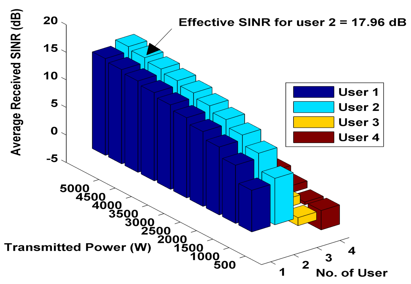
Figure 9 that under a scenario of transmitted power from a single BS, the estimated average minimum and maximum SINR values for user 1 through user 4 are 7.5464 dB and 17.5464 dB, 8.4224 dB and 18.4224 dB, −1.4506 dB and 8.5494 dB, and −3.5121 dB and 6.4879 dB, respectively. In 
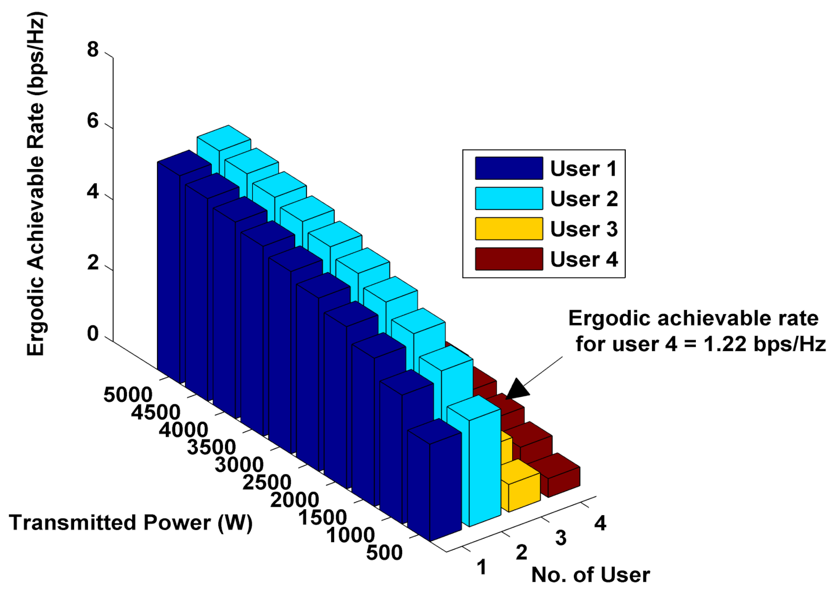
Figure 10, estimated ergodic achievable rate values are presented in the absence of CoMP-JT-based mmWave signal transmission and show that the estimated average received minimum and maximum ergodic achievable rate values for user 1 through user 4 are 2.7407 bps/Hz and 5.854 bps/Hz, 2.9917 bps/Hz and 6.1404 bps/Hz, 0.7791 bps/Hz and 3.0287 bps/Hz, and 0.5315 bps/Hz and 2.4474 bps/Hz, respectively.
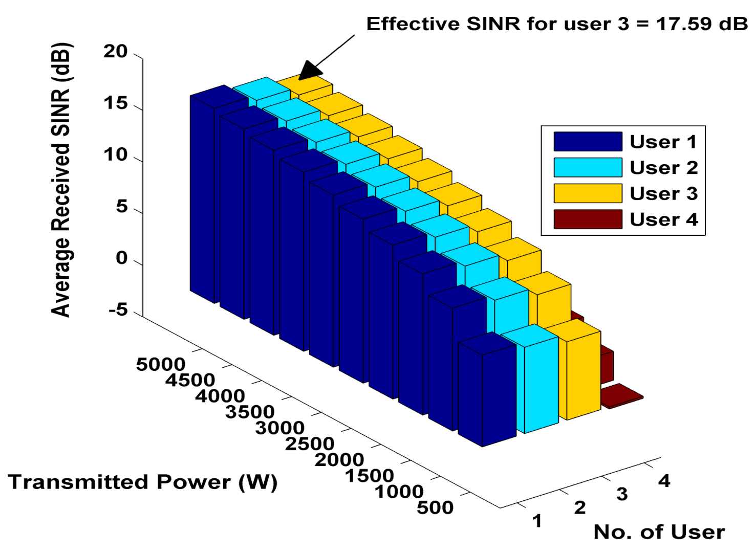
It is noticeable from Figure 11 that under a scenario of identical transmitted power from both BSs, the estimated average received minimum and maximum SINR values for user 1 through user 4 are 8.8834 dB and 18.8834 dB, 8.3532 dB and 18.3532 dB, 7.5883 dB and 17.5883 dB, and −0.2019 dB and 9.7981 dB, respectively. In Figure 12, estimated ergodic achievable rate values are presented under a scenario of identical transmitted power from both BSs and it shows that the estimated average received minimum and maximum ergodic achievable rate values for user 1 through user 4 are 3.126 bps/Hz and 6.2915 bps/Hz, 2.9716 bps/Hz and 6.1177 bps/Hz, 2.7525 bps/Hz and 5.8676 bps/Hz, and 0.9669 bps/Hz and 3.3986 bps/Hz, respectively.
By analyzing estimated values in Figure 9, Figure 10, Figure 11 and Figure 12, it is quite obvious that the implementation of CoMP-JT-based mmWave signal transmission improves both SINR and ergodic achievable rate.
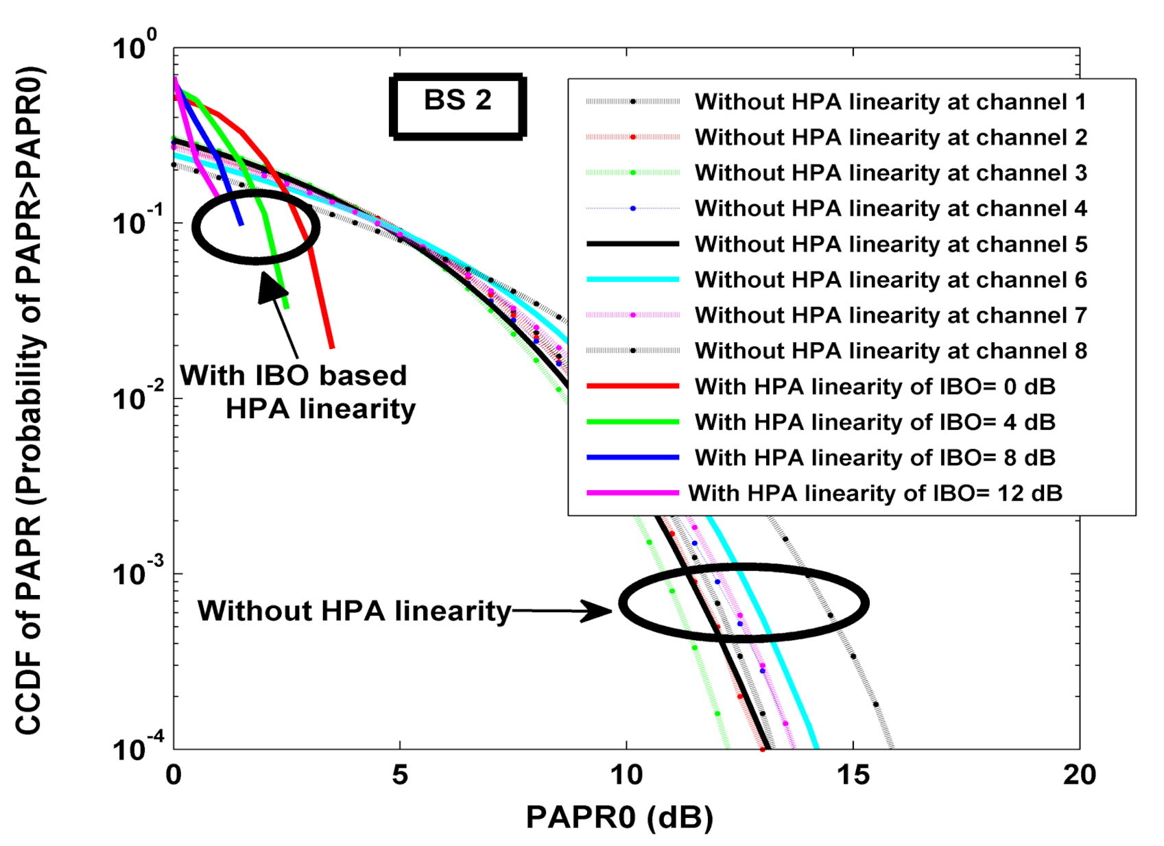
Complementary cumulative distribution functions (CCDFs) of PAPR for our proposed system with utilization of higher-order 16-QAM digital modulation are presented in Figure 13 and Figure 14. There is a clear illustration estimating that values of PAPR relative to their respective threshold values are greater in the case of the system without a PAPR reduction scheme using IBO-aided HPA. The probability of the output signals in different channels of BS 1 is 10 4 with PAPR greater than the threshold ranges from 12.5 dB to 15 dB. In such a case for 10 1 CCDF of PAPR, the output signals of all the channels are found to have almost identical 4 dB PAPR values. It is obvious from Figure 13 that in the case of 10 1 CCDF of PAPR with the application of IBO-based HPA, the output signal of the typically assumed first channel has PAPR (greater than the threshold) values of 3.0 dB, 2.2 dB, 1.5 dB, and 0 dB in the cases of 0 dB, 4 dB, 8 dB, and 12 dB IBO values. The probability of the output signals at different channels of BS 2 is 10 4 with PAPR greater than the threshold ranges from 12.2 dB to 15.9 dB. In such a case, for 10 1 CCDF of PAPR, the output signals of all the channels are found to have almost identical 4 dB PAPR values. It is quite obvious from Figure 14 that in case of 10 1 CCDF of PAPR with the application of IBO-based HPA, the output signal of the typically assumed first channel has PAPR (greater than the threshold) values of 2.9 dB, 2.0 dB, 1.5 dB, and 0 dB in the cases of 0 dB, 4 dB, 8 dB, and 12 dB IBO values.
In Figure 15, the estimated ergodic achievable rate for randomly distributed users over the study area of 2000 m 2 is presented both in a two-dimensional surface and three-dimensional contour plots (Figure 15a,b). The maximum and minimum values of the ergodic achievable rate are found to have values of 5.9635 bps/Hz and 0.1893 bps/Hz, respectively. In most parts of the studied area, the estimated average ergodic achievable rate is 3.2652 bps/Hz.
From Figure 16, it is observable that at a comparatively low base station antenna height, the estimated ergodic achievable rate values are increased in comparison with the scenario of base station antenna height. At the central location, 100 m away from the BS1, the estimated ergodic achievable rate with a transmission power of 500 W is found to have values of 0.6572 bps/Hz and 1.6679 bps/Hz in the cases of high and low base station antenna height. On the other hand, with a high transmission power of 5000 W, the estimated values of achievable ergodic are 2.7487 bps/Hz and 3.9008 bps/Hz for high and low base station antenna height.
The results in Figure 17 clearly indicate that an acceptable OOB reduction is achieved under 16-QAM higher-order digital modulation, RA channel coding, and CHT schemes. The OOB power reduction of 311.99 dB, 312.40 dB, 312.67 dB, and 312.34 dB are achieved in the cases of user 1, user 2, user 3, and user 4, respectively.
From Table 4, it is observable that a significant amount of PAPR reduction occurs with the application of IBO-based HPA. The estimated values of PAPR for different transmitting channels of serving BSs and IBO values under consideration of nonlinear HPA are shown in Figure 18. It is quite obvious from the figure that the PAPR performance of the system improves with low values of IBO.
By observing the nature of BER curves shown in Figure 19, Figure 20, Figure 21 and Figure 22, it can be clearly understood that the implementation of comparatively higher IBO produces an improvement of BER performance. To meet up a typically assumed BER of 10 4 , −2.5 dB and 4 dB SNR are required for a linear amplifier and 12 dB IBO with HPA, respectively, in the case of user 1, as shown in Figure 19. In the case of user 2, for the same BER of 10 4 , −1.7 dB and 3.8 dB SNR are required for linear amplifier and 12 dB IBO with HPA, respectively, as depicted in Figure 20. For user 3 in Figure 21, the SNR requirement is found to have values of −2.2 dB and 4.2 dB. In comparison with the systems without IBO-based HPA linearity, the BER performance in the case of user 4 for different values of IBO is moderate, as shown in Figure 22.
The authors in [36] made a comparative study on the suitability of a Walsh–Hadamard transformed (WHT) universal-filtered multicarrier (UFMC) system with classical OFDM and UFMC systems in terms of BER and SNR performance. The authors in [37] established improved performance of a double-tree complex wavelet transform (DTCWT)-based OFDM system in combination with the fast WHT (FWHT) and eliminated the drawbacks of the OFDM system. In [38], authors recommended a zero tail inverse lifting wavelet transform spread FWHT OFDM (ZT-ILWTs FWHT OFDM) system as an alternative to the conventional OFDM and presented better performance of their proposed system in terms of BER, PAPR, and OOB emission. In Figure 23, a comparative analysis has been illustrated in terms of BER against SNR between our proposed CoMP-JT-based mmWave CP-free multiuser OFDM system, WHT UFMC/fast WHTs and DTCWT-based OFDM, and ZT-ILWTs FWHT OFDM multicarrier signaling technique implemented systems. For a better view of the obtained values, Table 5 is also added. Under the scenario of systems without any channel coding scheme, the presented numerical results of our proposed uncoded system for a typically assumed case of user 1 is reasonably acceptable in comparison with the works of the other systems for BPSK, QAM, and 16-QAM digital modulations.

4. Conclusions and Future Challenges

In this study, the implementation of the CHT as well as BD channel precoding techniques in the CoMP-JT-transmission-method-based mmWave CP-free multiuser OFDM wireless communication system resulted in the reduction of multiuser interference. Moreover, subcarrier mapping for OOB reduction, IBO-aided HPA for PAPR reduction, and RA channel coding in particular for forward error correction has been introduced. Furthermore, the impact of the CoMP-JT-based transmission technique on SINR and ergodic achievable rate with the varying transmission power at mmWave is studied. In addition, ergodic achievable rates are also estimated with varying transmitting antenna height at a certain covered distance between two BSs.
The numerical results show that in mmWave transmission, the received signal power in proportion to transmitted signal power is comparatively very low within the covered transmission distance. This is due to the fact that the path loss is generally very high in mmWave transmission system as it is known from the literature that shorter wavelengths are usually impaired with strong reflections, refractions, and scattering. Although the developed simulated system is robust in terms of PAPR and OOB reduction as well as BER improvement with reasonably acceptable power spectral density, there is scope to improve the system under massive MIMO channels, e.g., the deployment of an antenna array at the BS utilizing more than 100 antenna elements; such a system under a massive MIMO scheme can notably provide an enormous increase in throughput [39]. In the future, the developed simulated system can surely be integrated with mMIMO and a transmit antenna selection technique to make it even more robust considering its improved performance [40,41].

Author Contributions

Conceptualization, J.J.S., S.R.S., S.E.U., R.R., and M.R.I.; methodology, J.J.S., S.R.S., and S.E.U., R.R., and M.R.I.; software, J.J.S., and S.E.U.; validation, J.J.S., S.E.U., M.A.H., and R.R.; formal analysis, J.J.S., S.R.S., S.E.U., and R.R.; investigation, J.J.S., S.R.S., and S.E.U.; resources, J.J.S., S.E.U., and R.R.; data curation, J.J.S., and S.E.U.; writing—original draft preparation, J.J.S., S.R.S., S.E.U., and R.R.; writing—review and editing, M.A.H., M.R.I., A.Z.K., and M.A.P.M.; supervision, S.E.U., R.R., M.R.I., and A.Z.K.; project administration, S.E.U., and R.R.; funding acquisition, R.R.; M.R.I., A.Z.K., and M.A.P.M. All authors have read and agreed to the published version of the manuscript.

Funding

This research received no external funding.

Institutional Review Board Statement

Not Applicable.

Informed Consent Statement

Not applicable.

Conflicts of Interest

The authors declare no conflict of interest.

References

  1. Alliance, N. Ran Evolution Project Comp Evaluation and Enhancement. NGMN Alliance NGMN_RANEV_D3_CoMP_Evaluation_ and_Enhancement_v2. 0. 2015. Available online: https://www.ngmn.org/wp-content/uploads/NGMN_RANEV_D3_CoMP_Evaluation_and_Enhancement_v2.0.pdf (accessed on 1 July 2021).
  2. Coordinated Multi-Point Operation for LTE Physical Layer Aspects; Technical Report; 3GPP Technical Report 36.819; SCIRP: Wuhan, China, 2013.
  3. Marotta, A.; Cassioli, D.; Antonelli, C.; Kondepu, K.; Valcarenghi, L. Network solutions for CoMP coordinated scheduling. IEEE Access 2019, 7, 176624–176633. [Google Scholar] [CrossRef]
  4. MacCartney, G.R.; Rappaport, T.S. Millimeter-wave base station diversity for 5G coordinated multipoint (CoMP) applications. IEEE Trans. Wirel. Commun. 2019, 18, 3395–3410. [Google Scholar] [CrossRef]
  5. Antonioli, R.; Parente, G.C.; e Silva, C.; Rodrigues, E.B.; Maciel, T.F.; Cavalcanti, F.R.P. Dual connectivity for LTE-NR cellular networks. Res. Gate 2017, 171–175. [Google Scholar]
  6. Kim, W. Dual connectivity in heterogeneous small cell networks with mmWave backhauls. Mob. Inf. Syst. 2016, 2016, 3983467. [Google Scholar] [CrossRef] [Green Version]
  7. Lauridsen, M.; Gimenez, L.C.; Rodriguez, I.; Sorensen, T.B.; Mogensen, P. From LTE to 5G for connected mobility. IEEE Commun. Mag. 2017, 55, 156–162. [Google Scholar] [CrossRef]
  8. Levanen, T.A.; Pirskanen, J.; Koskela, T.; Talvitie, J.; Valkama, M. Radio interface evolution towards 5G and enhanced local area communications. IEEE Access 2014, 2, 1005–1029. [Google Scholar] [CrossRef]
  9. Sano, Y.; Okuyama, S.; Iizasa, N.; Takada, T.; Ando, K.; Fujimura, N. 5G radio performance and radio resource management specifications. NTT DOCOMO Tech. J. 2019, 20, 79–95. [Google Scholar]
  10. Physical Layer (Version 15.0.0 Release 15); Technical Specification on 5G NR; Technical Report; 3GPP Technical Report 38.201; ETSI: Valbonne, France, 2018.
  11. Physical Channels and Modulation (Version 15.5.0 Release 15); Technical Specification on 5G NR; Technical Report, 3GPP Technical Report 38.211; ETSI: Valbonne, France, 2018.
  12. Mei, L.; Fang, X.; Lin, X.; Shi, Z.; Wang, J. A WFRFT-based Cyclic Prefix-Free Hybrid-Carrier FDE scheme. In Proceedings of the 2020 IEEE 91st Vehicular Technology Conference (VTC2020-Spring), Antwerp, Belgium, 25–28 May 2020; pp. 1–6. [Google Scholar]
  13. Mohammadkarimi, M.; Ardakani, M. Optimal channel equalizer for mmWave massive MIMO using 1-bit ADCs in frequency-selective channels. IEEE Commun. Lett. 2020, 24, 882–885. [Google Scholar] [CrossRef]
  14. Kosasih, A.; Hardjawana, W.; Vucetic, B.; Wen, C.K. A Linear Bayesian Learning Receiver Scheme for Massive MIMO Systems. In Proceedings of the 2020 IEEE Wireless Communications and Networking Conference (WCNC), Seoul, Korea, 25–28 May 2020; pp. 1–6. [Google Scholar]
  15. Yu, J.L.; Zhang, B.; Yuan, Y.; Hsu, W.T. Blind channel identification for cyclic-prefixed MIMO-OFDM systems with virtual carriers. China Commun. 2020, 17, 101–116. [Google Scholar] [CrossRef]
  16. Zhou, Z.; Liu, L.; Chang, H.H. Learning for detection: MIMO-OFDM symbol detection through downlink pilots. IEEE Trans. Wirel. Commun. 2020, 19, 3712–3726. [Google Scholar] [CrossRef] [Green Version]
  17. Zhang, J.; Wen, C.K.; Jin, S.; Li, G.Y. Artificial intelligence-aided receiver for a CP-free OFDM system: Design, simulation, and experimental test. IEEE Access 2019, 7, 58901–58914. [Google Scholar] [CrossRef]
  18. Zhou, X.; Zhang, J.; Wen, C.K.; Zhang, J.; Jin, S. Model-Driven Deep Learning-Based Signal Detector for CP-Free MIMO-OFDM Systems. In Proceedings of the 2021 IEEE International Conference on Communications Workshops (ICC Workshops), Montreal, QC, Canada, 14–23 June 2021; pp. 1–6. [Google Scholar]
  19. Üçüncü, A.B.; Güvensen, G.M.; Yılmaz, A.Ö. A Reduced Complexity Ungerboeck Receiver for Quantized Wideband Massive SC-MIMO. IEEE Trans. Commun. 2021, 69, 4921–4936. [Google Scholar]
  20. Kizawa, M.; Ikegami, T. GSC-based equalizer with QR decomposition for CP-Free MIMO-OFDM systems. IEICE Commun. Express 2021. [Google Scholar] [CrossRef]
  21. Chuang, Y.; Ueng, F.B.; Shen, Y.S. A Cyclic Prefix Free Multiple Input Multiple Output Generalized Frequency Division Multiplexing System Design. Wirel. Pers. Commun. 2021, 117, 311–336. [Google Scholar] [CrossRef]
  22. Hai, H.; Jiang, X.Q.; Duan, W.; Li, J.; Lee, M.H.; Jeong, Y. Complex Hadamard Matrix-Aided Generalized Space Shift Keying Modulation. IEEE Access 2017, 5, 21139–21147. [Google Scholar] [CrossRef]
  23. Rahardja, S.; Falkowski, B.J. Digital signal processing with complex Hadamard transform. In Proceedings of the ICSP’98—1998 Fourth International Conference on Signal Processing (Cat. No. 98TH8344), Beijing, China, 12–16 October 1998; pp. 533–536. [Google Scholar]
  24. Uwaechia, A.N.; Mahyuddin, N.M. A comprehensive survey on millimeter wave communications for fifth-generation wireless networks: Feasibility and challenges. IEEE Access 2020, 8, 62367–62414. [Google Scholar] [CrossRef]
  25. Rappaport, T.S. Wireless Communications: Principles and Practice; PTR Prentice Hall: Englewood Cliffs, NJ, USA, 1996; Volume 2. [Google Scholar]
  26. Mironov, R.P.; Kountchev, R.K. Complex Hadamard transform of digital signals: Properties and applications. Int. J. Reason.-Based Intell. Syst. 2012, 4, 3–16. [Google Scholar] [CrossRef]
  27. Lien, S.Y.; Shieh, S.L.; Huang, Y.; Su, B.; Hsu, Y.L.; Wei, H.Y. 5G new radio: Waveform, frame structure, multiple access, and initial access. IEEE Commun. Mag. 2017, 55, 64–71. [Google Scholar] [CrossRef]
  28. Myung, H.G.; Goodman, D.J. Single Carrier FDMA: A New Air Interface for Long Term Evolution; John Wiley & Sons: Hoboken, NJ, USA, 2008; Volume 8. [Google Scholar]
  29. Di Zenobio, D.; Santella, G.; Mazzenga, F. Adaptive linearization of power amplifier in orthogonal multicarrier schemes. In Proceedings of the IEEE Wireless Communication System Symposium, Long Island, NY, USA, 27–28 November 1995; pp. 225–230. [Google Scholar]
  30. Majumdar, I. Block Diagonalization Type Precoding Algorithms for IEEE 802.11 ac Systems. arXiv 2018, arXiv:1801.00563. [Google Scholar]
  31. Cho, Y.S.; Kim, J.; Yang, W.Y.; Kang, C.G. MIMO-OFDM Wireless Communications with MATLAB; John Wiley & Sons: Hoboken, NJ, USA, 2010. [Google Scholar]
  32. Alias Isakki, R.M.; Tharini, C.; Arulvani, M. Performance analysis of pulse shape filter for repetition channel coding. In Proceedings of the 2017 IEEE International Conference on Power, Control, Signals and Instrumentation Engineering (ICPCSI), Chennai, India, 21–22 September 2017; pp. 592–597. [Google Scholar]
  33. MacCartney, G.R.; Samimi, M.K.; Rappaport, T.S. Omnidirectional path loss models in New York City at 28 GHz and 73 GHz. In Proceedings of the 25th Annual International Symposium on Personal, Indoor, and Mobile Radio Communication (PIMRC), Washington, DC, USA, 2–5 September 2014; pp. 227–231. [Google Scholar]
  34. 405—Transmitter Power Limitations. Available online: https://ecfr.federalregister.gov/current/title-47/chapter-I/subchapter-B/part-30/subpart-E/section-30.405 (accessed on 1 July 2021).
  35. Yan, Z. 5G: On the Verge of a Smart Future. Available online: https://www.huawei.com/en/technology-insights/publications/huawei-tech/85/5g-on-verge-of-smart-future (accessed on 1 July 2021).
  36. Ayvaz, E.N.; Maraş, M.; Gömec, M.; Özen, A. An WHT Spread UFMC Waveform Design for the Next Generation Wireless Communications. In Proceedings of the 2019 IEEE 27th Signal Processing and Communications Applications Conference (SIU), Sivas, Turkey, 24–26 April 2019; pp. 1–4. [Google Scholar]
  37. Karaerik, K.; Tuna, E.B.; Tek, Y.İ.; Sinop, H.; Yaşar, S.; Avcı, B.; Aykırı, G.; Özen, A. A Novel Double Tree Complex Wavelet Transform OFDM Based on Fast Walsh Hadamard Transform. In Proceedings of the 2020 IEEE International Conference on Electrical, Communication, and Computer Engineering (ICECCE), Istanbul, Turkey, 12–13 June 2020; pp. 1–4. [Google Scholar]
  38. Cengiz, C.; Bilbay, Ö.; Akıllı, A.H.; Sert, S.; Özen, A. A New Waveform Design based on Sequentially Connected ILWT and FWHT Transforms. In Proceedings of the 2020 IEEE 43rd International Conference on Telecommunications and Signal Processing (TSP), Milan, Italy, 7–9 July 2020; pp. 672–676. [Google Scholar]
  39. Björnson, E.; Hoydis, J.; Sanguinetti, L. Massive MIMO networks: Spectral, energy, and hardware efficiency. Found. Trends Signal Process. 2017, 11, 154–655. [Google Scholar] [CrossRef]
  40. Khan, M.; Rahman, M.T.; Sabuj, S.R. A transmit antenna selection technique in random cognitive radio network. In Proceedings of the TENCON 2018—2018 IEEE Region 10 Conference, Jeju, Korea, 28–31 October 2018; pp. 0264–0267. [Google Scholar]
  41. Sabuj, S.R.; Hamamura, M. Outage and energy-efficiency analysis of cognitive radio networks: A stochastic approach to transmit antenna selection. Pervasive Mob. Comput. 2017, 42, 444–469. [Google Scholar] [CrossRef]
Figure 1. Dual connectivity of user equipment (UE) with macro eNB and small-cell eNB.
Applsci 11 07605 g001
Figure 2. A scenario of CoMP-JT-based mmWave signal transmission from two BSs to four users.
Applsci 11 07605 g002
Figure 3. Block diagram of CoMP-JT-based downlink CP-free multiuser OFDM communication system.
Applsci 11 07605 g003
Figure 4. Flow-chart of the simulated work.
Applsci 11 07605 g004
Figure 5. BER performance of the considered system with utilization of various channel coding, higher−order digital modulation, and ZF signal detection technique for user 1.
Applsci 11 07605 g005
Figure 6. BER performance of the considered system with the utilization of various channel coding, higher−order digital modulation, and ZF signal detection techniques for user 2.
Applsci 11 07605 g006
Figure 7. BER performance of the considered system with utilization of various channel coding, higher−order digital modulation, and ZF signal detection techniques for user 3.
Applsci 11 07605 g007
Figure 8. BER performance of the considered system with utilization of various channel coding, higher−order digital modulation, and ZF signal detection techniques for user 4.
Applsci 11 07605 g008
Figure 9. Estimated average received SINR versus transmitted power in absence of CoMP−JT−based mmWave signal transmission.
Applsci 11 07605 g009
Figure 10. Estimated ergodic achievable rate versus transmitted power in absence of CoMP−JT−based mmWave signal transmission.
Applsci 11 07605 g010
Figure 11. Estimated average received SINR versus transmitted power in presence of CoMP−JT−based mmWave signal transmission.
Applsci 11 07605 g011
Figure 12. Estimated ergodic achievable rate versus transmitted power in presence of CoMP−JT−based mmWave signal transmission.
Applsci 11 07605 g012
Figure 13. CCDFs of PAPR for the considered system with and without the utilization of an IBO−aided PAPR scheme at BS 1.
Applsci 11 07605 g013
Figure 14. CCDFs of PAPR for the considered system with and without the utilization of IBO−aided PAPR scheme at BS 2.
Applsci 11 07605 g014
Figure 15. Estimated ergodic achievable rate under the studied area of 200 m × 100 m serving two BSs of identical height at 100 m and transmission power of 5 kW represented by (a) a two−dimensional surface plot and (b) a three−dimensional contour plot.
Applsci 11 07605 g015
Figure 16. Estimated ergodic achievable rate along a profile of length 200 m connecting the two transmitting BSs of varying antenna height and transmission power.
Applsci 11 07605 g016
Figure 17. Power spectral density of the considered system with the implementation of 16−QAM higher−order digital modulation, RA channel coding, and CHT schemes for the cases of (a) user 1, (b) user 2, (c) user 3, and (d) user 4.
Applsci 11 07605 g017
Figure 18. Estimated PAPR at different transmitting channels of serving BSs and IBO under nonlinear HPA implementation.
Applsci 11 07605 g018
Figure 19. BER performance of the considered system with and without implementation of IBO-based HPA for the case of user 1.
Applsci 11 07605 g019
Figure 20. BER performance of the considered system with and without implementation of IBO-based HPA for the case of user 2.
Applsci 11 07605 g020
Figure 21. BER performance of the considered system with and without implementation of IBO-based HPA for the case of user 3.
Applsci 11 07605 g021
Figure 22. BER performance of the considered system with and without implementation of IBO-based HPA for the case of user 4.
Applsci 11 07605 g022
Figure 23. BER performance comparison between the proposed uncoded system with other multicarrier uncoded systems.
Applsci 11 07605 g023
Table 1. Summary of related technologies, merits, and demerits.
ReferenceSchemesMeritsDemerits
[13]mMIMOLow power consumptionSingle bit analog-to-digital converter
[14]mMIMOLow computational complexity and latency×
[15]MIMOMedium computational complexity×
[16]MIMOImproved short-term memory and interference cancellation×
[17]SISOLow computational complexityDifficulty in channel estimation
[18]MIMO×High complexity
[19]MIMOLow power consumption, cost, and low complexity×
[20]MIMOLow complexity×
This paperMIMOLow computational complexity and cost×
Table 2. Simulation Parameters.
DescriptionValue
FFT size4096
Effective subcarriers3300
No of CP free OFDM symbol32
Subcarrier spacing (KHz)60
Sampling frequency (MHz)245.76
Carrier Bandwidth (MHz)200
System Bandwidth (MHz)250
Transmission Power from each BS (Watt)5000
Antenna configuration 2 × 8
Signal-to-Noise ratio (dB)−10 to 10
Spreading factor of spreading codes8
Data length (binary bits) per user26,400
Table 3. Estimated signal power at both the BS and user end.
DescriptionValue
Average Transmit power of BS 15000 W (66.9897 dBm)
Average Transmit power of BS 25000 W (66.9897 dBm)
Original signal power and interference signal power of user 1 7.7329 × 10 11  W and 2.4999 × 10 41  W
Original signal power and interference signal power of user 2 5.7999 × 10 4  W and 1.8913 × 10 34  W
Original signal power and interference signal power of user 3 4.8633 × 10 4  W and 2.0287 × 10 34  W
Original signal power and interference signal power of user 4 8.0893 × 10 5  W and 2.0519 × 10 34  W
Table 4. Estimated PAPR at different channels of BS.
Channel No.PAPR (dB)
Without IBO-BasedWith IBO-Based Nonlinear HPA
Nonlinear HPAIBO = 0 dBIBO = 4 dBIBO = 8 dBIBO = 12 dB
BS1BS2BS1BS2BS1BS2BS1BS2BS1BS2
114.961515.44752.41462.75763.36883.75555.09635.49707.59877.9265
215.493914.92812.68782.41483.79173.33545.55335.05767.96197.5681
316.930513.87582.42842.36543.32773.24265.04124.95047.55417.4802
416.462916.60692.49652.52743.47263.49585.19895.21567.67187.6822
514.625414.75402.39282.48543.26023.39894.95595.09957.47807.5866
614.171415.51992.34822.72563.20433.79224.90515.51867.44307.9174
713.747915.31382.45562.54573.38433.48055.09935.18677.59447.6599
814.493417.47702.43652.67613.36543.74105.08505.48297.58517.9025
Table 5. Estimated BER Values in Comparative Study.
SNR (dB)Bit Error Rate (BER)
Proposed SystemWHT SpreadDTCWT–FWHTZT-ILWTs FWHT
UFMC SystemOFDM SystemOFDM System
Digital ModulationDigital Modulation
16-QAMQAMBPSK16-QAMQAMBPSK
−50.0510.0330.0160.3900.2000.096
−30.0220.0140.0060.3600.1200.066
00.0030.0020.0000.2800.0470.035
30.0000.0000.0000.2400.0290.020
50.0000.0000.0000.1700.0190.010
70.0000.0000.0000.1400.0100.007
90.0000.0000.0000.1000.0080.005
Publisher’s Note: MDPI stays neutral with regard to jurisdictional claims in published maps and institutional affiliations.

