Article

Copyright Protection of 3D Digitized Artistic Sculptures by Adding Unique Local Inconspicuous Errors by Sculptors

1
Faculty of Technical Sciences, University of Novi Sad, 21000 Novi Sad, Serbia
2
Faculty of Mechanical Engineering, University of Belgrade, 11000 Beograd, Serbia
3
Gallery of Matica Srpska, 21000 Novi Sad, Serbia
4
School of Engineering, Newcastle University, Newcastle upon Tyne NE1 7RU, UK
*
Authors to whom correspondence should be addressed.
Appl. Sci. 2021, 11(16), 7481; https://doi.org/10.3390/app11167481
Submission received: 17 July 2021 / Revised: 7 August 2021 / Accepted: 10 August 2021 / Published: 14 August 2021

Abstract

:
In recent years, digitization of cultural heritage objects, for the purpose of creating virtual museums, is becoming increasingly popular. Moreover, cultural institutions use modern digitization methods to create three-dimensional (3D) models of objects of historical significance to form digital libraries and archives. This research aims to suggest a method for protecting these 3D models from abuse while making them available on the Internet. The proposed method was applied to a sculpture, an object of cultural heritage. It is based on the digitization of the sculpture altered by adding local clay details proposed by the sculptor and on sharing on the Internet a 3D model obtained by digitizing the sculpture with a built-in error. The clay details embedded in the sculpture are asymmetrical and discreet to be unnoticeable to an average observer. The original sculpture was also digitized and its 3D model created. The obtained 3D models were compared and the geometry deviation was measured to determine that the embedded error was invisible to an average observer and that the watermark can be extracted. The proposed method simultaneously protects the digitized image of the artwork while preserving its visual experience. Other methods cannot guarantee this.

1. Introduction

Intensive development of techniques for 3D modeling and 3D digitization of cultural heritage (movable and immovable), such as photogrammetry [1], has led to the issue of protection and rights to take over the obtained 3D models. Although the problem of data protection against theft and misuse of various other types of digital information (software, software code, audio, and video files) has previously been solved [2], few solutions have been created to protect 3D models. The growing use of 3D digitization of cultural heritage objects, which has flourished in recent years, has significantly increased the need to protect 3D models. More and more cultural institutions use the mentioned modern methods of 3D digitalization to create high-quality, realistic 3D models of objects of historical significance. More and more projects financed/supported by the state, cultural institutions, and the competent ministry are based on the digitization of cultural heritage and the creation of digital libraries and archives [3,4,5]. Moreover, the creation of virtual museums [6] and virtual presentations of cultural heritage, which use innovative technologies such as virtual and augmented reality, is becoming increasingly popular [7]. The 3D models created by digitization of objects within such projects are the heritage of the cultural institutions and countries, and the contract allows the distribution of the obtained 3D models to a certain group of people (mostly employees of cultural institutions or scientists) for non-commercial use. Although the majority of the population would like 3D models to be widely available to be used for various, even commercial purposes, 3D models of objects of cultural significance can be abused if they are distributed without protection. The fear of copying their work and stealing ideas (based on 3D models) is also present among the curators. The term abuse refers to the download of 3D digital models from the Internet and their distribution by users who present someone else’s work as their own.
One of the standard ways to protect digital content is licensing, in the case of software or music sharing, but in the case of the 3D virtual models, cryptography is the solution [8]. In modern times, the dominant way of protecting an artwork is the watermark. The digital preservation policies in most cultural heritage institutions are not developed and the created archives are technologically obsolete [9]. A bridge between physical engineering and cyber-crime is 3D printing because digital contents created or stolen in one country or institution can be transported around the world via the Internet to be physically created. In many countries, the laws are too primitive to cover similar types of cyber-crime [10]. Digital archives and digital cultural heritage contents require special skills to manage the copyrights and intellectual properties. The relationship between intellectual property and digitization has not been fully legally regulated [11]. The process of protection of intellectual property rights requires consideration of issues relating to the balance between fair conditions for access to cultural heritage objects for digitization and modern media for presentation [12]. In addition to the issue of intellectual property in the digitization of objects of cultural significance and their presentation, it is necessary to take into account ethical principles and issues [13].
Despite the growing need for protection against the misuse of digital 3D models of cultural heritage, little research addresses this issue. Watermarks are described as structures containing information that is embedded into objects so that they do not interfere with the intended use [14]. The authors presented fundamental techniques and algorithms for embedding data into the geometry of 3D models. They noted three requirements that are common to a majority of applications: watermarks must be unnoticeable, robust, and space efficient. The authors suggest geometry as the best candidate for data embedding in a 3D model compared to another attribute such as shininess, surface or vertex colors, surface or vertex normal vectors, per-vertex texture coordinates, or texture images. They have shown that the embedding of a watermark can be achieved by action on the surface vertices (e.g., inserting or displacing vertices) or on the surface topology (connectivity). Such watermark embeddings are used for copyright notification or protection, theft deterrence, and inventory of 3D polygonal models [15].
The need for centralized 3D cultural heritage archives was stressed through different projects described in [16]. Authors listed several such projects, two of them created by the Stanford University: the 3D archive of Michelangelo’s sculpture [17] and the Forma Urbis Romae [18]. The first project refers to the digitization of ten sculptures, including Michelangelo’s David and the second is a giant marble map of Rome constructed in the early 3rd century. In both projects, the 3D models and raw data are distributed only to the established scientists due to the contract with the Italian authorities. The 3D content is available to the general public in a reduced form through a new remote display system named “ScanView”. They also presented a 3D reconstruction of the Roman Forum, which is developed at UCLA [19]. The authors showed two approaches to protect 3D models: watermarking 3D model and a trusted 3D graphics pipeline. In this pipeline, a ScanView prevents theft of a 3D model’s geometry by providing the user with only a low-resolution 3D model version. When the user requests a view of the model, a high-resolution 3D model is rendered on the server, which is in the same position as the low poly model, and its view is sent to the user.
To analyze the protection of 3D models, we have researched on the Internet a number of techniques for sharing 3D models in a safe and secure way. One of the ways that are often mentioned is watermark [14,20,21,22,23,24,25,26,27,28,29,30]. In this research, we will use an example of a sculpture to describe and present our conceptual solution for the protection of 3D models created by 3D digitization of cultural heritage (i.e., 3D models in general) from misuse and copying. The sculpture shows the upper part of a human figure (head, neck, and part of the torso) cast in plaster. The object is dominated by golden-yellow color, but darker shades of brown are also present. The emphasis was on the digitization of the head/face of the sculpture, with dimensions: width × height × depth = 203 mm × 254 mm × 203 mm. Our idea is to add masses with clay in a color that corresponds to the color of the sculpture to the parts of the sculpture. The curator (sculptor) from the Gallery of Matica srpska, which is a representative cultural institution, supported our idea as a meaningful solution, and his proposal was to add these masses to a lock of hair (on the left side), the earlobe (on the left side), and the cheekbone (on the left side), i.e., the parts of the sculpture where those masses would be unnoticeable to an average observer. Moreover, for the same reason, the amount of clay applied was taken into account. Attention was also focused on avoiding any damage to the sculpture both during the application of the clay and in the process of digitization. In this research, the emphasis was on the use of contactless methods for digitization to avoid unintentional damage to the sculpture. We used photogrammetry, because of relative simplicity and the need for minimal hardware and software resources, as well as satisfactory accuracy. In addition to photogrammetry, another 3D digitization technique we used is 3D digitization with structured light (fringe projection method). The reason for this is that this technique is not time-consuming and provides models with a high level of detail. Due to its relative simplicity and the need for minimal hardware and software resources, as well as satisfactory accuracy, photogrammetry is one of the better available solutions for 3D digitization. In addition to photogrammetry, in this case, 3D digitization with structured light (fringe projection method) is also a good solution.

1.1. Photogrammetry

Nowadays, with the development of software for 3D reconstruction and image processing, photogrammetry becomes an easy and inexpensive method for 3D reconstruction of cultural heritage [31]. Great importance of photogrammetry for the reconstruction of cultural heritage objects is the fact that it is a contactless and non-destructive method. In photogrammetry, image or data processing implies creating the 3D geometry of an object from a set of images performed by the software. Popular photogrammetry software is user-friendly and automatized. There are various open-source software for image-based modeling, such as AliceVision, VisualSFM, COLMAP, OpenMVS, and Regard 3D, as well as commercial software, such as Reality Capture, Autodesk Recap Photo, Context Capture, and AgiSoft Metashape [32,33,34,35]. There is also GRAPHOS, an automatic open-source software, which, in addition to advanced automatic tools for photogrammetric reconstruction, also has a well-developed educational component [36].
To obtain a precise, detailed, and photo-realistic 3D model that is useful for visualization or documentation, it is necessary to meet certain criteria [37]. Structure from motion (SfM) is a method for photogrammetric surveying in which camera positions and orientation must be precisely determined. Careful planning and correct photos acquisition allow the generation of accurate and realistic 3D textured models with low-cost photographic equipment [38,39]. This means that special attention has to be given to the design of the surveying plan [37]. One of the factors that photogrammetric surveying favors is diffuse lighting. Therefore, a precisely created shooting plan and diffused lighting guarantee successful photogrammetric surveying.
After the photographs are collected, the photogrammetric reconstruction is done in a few main steps: building dense point cloud, generating the mesh, and obtaining texture projection from the photographs. The final result of the photogrammetric modeling is a highly detailed and realistic representation of an object geometry (its 3D model), with realistic texture representation [7].

1.2. 3D Scanning

In recent years, 3D scanning has become a widespread technique for collecting 3D images of cultural heritage artifacts, in the areas of small historic objects [40,41,42], sculptures [43,44,45,46], rooms [47,48], or large buildings and entire architectural sites [49,50,51,52]. Structured lighting technology is suitable for the digitization of cultural heritage objects because it is a contactless method for 3D digitization [53]. Another reason for the widespread use of 3D scanners in the process of digitization of cultural heritage is the high precision of the obtained models [54,55] as well as the fact that the 3D model can be obtained relatively quickly [56]. Scan results are visible in real-time in the appropriate software that is created for post-processing the data collected.
The technique of 3D laser scanning developed during the last half of the 20th century in an attempt to accurately reconstruct the surfaces of different objects and places and with the advent of the computers [57]. The 3D laser scanner, which works on the basis of structured light, projects a pattern of light on the subject and notes the deformation of the pattern on the subject and thus collects data on the shape of the object it scans. A real-time scanner, which uses digital fringe projection, was developed, to capture, reconstruct, and render high-density details of objects [58].

2. Related Works

One of the common methods for creating a robust and blind watermarking scheme for protecting digital and printed 3D models is based on embedding the watermark along the pre-defined axis and printing the 3D model in the same direction because the layer thickness and printing direction affect the accuracy and detail of the printed model [59,60]. In this scheme, the layers of the 3D model are treated as a template that provides information about the orientation of the watermark in the procedure of watermark detection. Giao Pham et al. [61] created and presented an algorithm for copyright protection of 3D models based on embedding watermark data in the characteristic points of 3D models. The main goal of the algorithm is to cut the 3D digital model into slices along the Z-axis. Authors pointed out that the methods presented earlier for watermarking 3D models based on geospatial domain (changing topology, length, area, or value of the vertices or geometric features) or frequency domain (such as discrete Fourier transform, discrete wavelet transform [62], or discrete cosine transform) are useful for copyrights protection of the digital 3D models but not for physical and printed 3D models. The same authors created an algorithm for copyright protection of 3D printed models based on Menger facet curvature and K-mean clustering [20]. Another algorithm based on slices of 3D mesh, which are embedded into watermark data, was also presented [21]. The coordinates of each point in the obtained 2D slices are changed according to the changed mean distance value of the 2D slice. For constructing a robust watermark on the 3D model (mesh) and creating a set of scalar basis functions over the mesh vertices, it is necessary to use multiresolution analysis [22]. The watermark perturbs vertices along the direction of the surface normal, and it was weighted by the different basis functions such as hat, derby, and sombrero. The watermark is reliable in the case of a wide variety of attacks such as vertex reordering, noise addition, similarity transforms, cropping, smoothing, simplification, and insertion of a second watermark. Methods that are based on readjustment of the distances from the mesh faces to the mesh center calculate the distance from the face center to the mesh center as Euclidean distance [23,24].
There are also methods for creating a watermark based on determining perceptually conspicuous regions over the given 3D mesh based on mesh saliency [25]. The mesh saliency is based on Gaussian function and depends on the parameter that is set arbitrarily [63]. After extracting salient regions from the 3D mesh, the authors embedded a watermark into these regions, and this is the second phase. For this purpose, they used the statistical approach [26]: for each vertex from the extracted salient region, the authors calculated vertex norm as the distance between the vertex and barycenter of the 3D mesh. According to the size of a given vertex norms in comparison with other vertices, a watermark is added to the observed vertex. The presented method takes into account that the visual appearance of the 3D shape is undisturbed, which is a special quality of this work.
Every blind, non-reversible fragile watermarking algorithm is created to protect the integrity of 3D models [27]. An algorithm that does not require the existence of a host object is blind; otherwise, it is non-blind [28]. An algorithm that can recover the original data is reversible; otherwise it is named lossy or non-reversible. A digital watermark can be robust, semi-fragile, and fragile. A fragile watermark creates a minimal modification of the digital object, and its fields of application are integrity protection and authentication. The authors systematized paper [61], showing robust watermarking and fragile watermarking. They also presented the discrete Karhunen–Loève transform (KLT), which is a linear transformation that maps vectors from one n-dimensional vector space to another vector space of the same dimension. The proposed algorithm protects model geometry (vertex coordinates) and topology (polygon structure) but not texture properties and normals. Some different techniques add watermark according to volume moment [29]. The first step is the conversion of mesh vertex coordinates from the Cartesian system to the cylindrical system. This step is called mesh normalization. After the normalization of the mesh, the mesh is divided into patches and its h and θ domains are discretized in the cylindrical system. For patches selected to participate in the watermark-embedding step, it is necessary to insert some auxiliary vertices that are removed after the watermark-embedding procedure is performed. Patch modification is performed iteratively. Deformation of the patches is performed by a smooth mask so as to be invisible to the average observer.
There are three approaches to copyright protections of digital content, namely cryptography, digital rights management (DRM), and digital watermarking and fingerprinting [64]. The authors created three scenarios for the illegal distribution of 3D content: digital sharing environment for 3D objects without 3D printing, sharing the printed model obtained from the digital model, and sharing the original printed model by the author. They also showed two approaches to copyright protections for 3D content, which are digital domain techniques and additional hardware and material addition. Digital Domain techniques are non-blind watermarking, blind watermarking, and watermark inside a printed 3D object. On the other hand, additional hardware and material involves the use of radio-frequency identification (RFID) tags, then using spectral signatures produced from chemical taggants, as well as 3D printing anti-counterfeiting technology based on quantum dot detection [65,66]. This method is based on quantum dots that are added randomly to the object itself, thus creating a unique physically unclonable fingerprint known only to the manufacturer.
An original embedding algorithm for the secure transmission of 3D polygonal mesh through a sensor network was presented in [30]. This method is based on “prongs” selecting, i.e., on selecting prominent feature vertices as common descriptors of 3D surfaces. The authors used protrusive feature vertices because these regions contain the most information about the surface shape. The method is robust against the cropping attack, noise, smoothing, and mesh simplification. The geometrical data of the automatically restituted 3D model of the Chateau de Versailles are protected by using optimized adaptive sparse quantization index modulation (QIM) for embedding some data bits into a 3D-generated model [67].
An efficient selective encryption method for 3D object binary formats was also created [68]. Geometrical distortions are introduced to partially or fully protect the 3D content and the authors partially encrypt the floating representation of coordinates of vertices using a secret key. This method encrypts selected bits of the 3D model geometry to visually protect it and this procedure happens without increasing the file size.

3. Materials and Methods

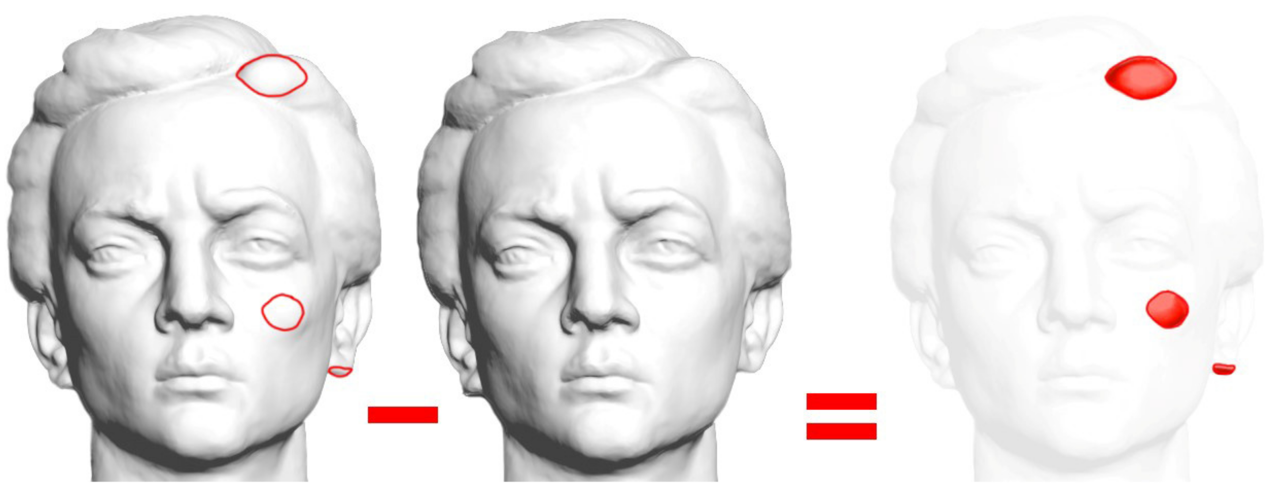
3.1. Proposed Algorithm

The main idea of our research is that instead of the 3D model obtained by 3D digitization of the original sculpture, a 3D model obtained by 3D digitization of the sculpture with a built-in “sculptural error” will be exposed to the public. Namely, the sculptor added clay to the original sculpture, according to his own experience and discretion, in places on the sculpture that he thought would be the least visually noticeable. So, he chose three segments on the face, which can be seen in Figure 1. We called this sculpture a sculpture with an error, and its 3D model is called a 3D model with a digital error. After digitizing the sculpture with added clay, the sculptor easily and without damaging the sculpture removed the applied material. In this paper, built-in error or protection are synonyms for added clay. We used the term protection because it suggests protection of the rights of the owner (copyrights).
If we wanted to show the general public the original sculpture in high resolution, that is, its 3D model, we would actually show the 3D model of a digitized sculpture with a digital error. The assumption is that an average observer, that is, a visitor to museums and cultural institutions and their sites, would not notice the digital error that has been added to the model. Especially since a 3D model of the original sculpture would not be placed on the site, so it would not be possible to compare the sculpture with a digital error with the original sculpture. Therefore, in the event of any misuse of the displayed 3D model with a digital error, for example, if someone tried to print a 3D model of that sculpture, the authors who made the sculpture available to the public could easily establish the originality of each copy of the sculpture that appears anywhere in the world. This would be achieved by creating a 3D model of the printed copy of the sculpture and comparing it to a 3D model of the original sculpture that was not even shown to the public.
In this research, the digitized object is the original sculpture owned by the Gallery of Matica srpska, a cultural institution of national importance situated in Novi Sad, Serbia. After the original object has been digitized, the material was discreetly added to the sculpture in several places by the sculptor/curator, with the idea that an average observer would not notice the change. The sculpture thus corrected was digitized again. After that, the geometry on the digital models of the original sculpture and the sculpture with a defect was compared. It was found that the added physical error can be accurately detected by comparing the two models. To detect the difference between the 3D models of the two sculptures, the software MeshLab [69] and CloudCompare [70] were used. They were used to compare the Euclidean distances between the corresponding vertices on the point cloud of the original sculpture (MeshLab used a mesh surface) and the point cloud of the sculpture with built-in error. It is important to say that the 3D model of the original sculpture must not be available to the public but must be archived and protected by those who digitized the sculpture. This means that the 3D model of the original sculpture will not even be placed on the server where the presentation of the cultural institution is located. In this way, the general public would have the opportunity to observe, analyze, and enjoy all the beauties of many works of art that are part of the cultural heritage, but the possibility of their abuse is eliminated. It is also assumed that the artwork observers do not need to perceive the exact 3D model of the sculpture and that their experience of the beauty of the work of art will in no way be diminished.

3.2. Digitization Process

The sculpture shown in Figure 1 was 3D digitized using two non-contact methods: photogrammetry and fringe projection. First, the sculpture was 3D digitized without added masses of clay. In this way, the data on the original form/appearance of the work of art were collected. After the sculpture was scanned in both ways, the curator/sculptor from the Gallery of Matica srpska added clay to the parts of the sculpture, namely a lock of hair (on the left side), an earlobe (on the left side), and a cheekbone (on the left side). The masses were added, according to the sculptor’s feeling, to the parts where they would be unnoticeable by an average observer and in an amount that is also unnoticeable by the observer. Namely, part of this research includes a survey of 195 respondents, which is described in Section 4.3. When the masses were added, the sculpture was again 3D digitized, by photogrammetry and structured light. This digitized sculpture was called a sculpture with a digital error. For both types of 3D digitalization, photogrammetry, and 3D digitization with structured light (fringe projection method), we digitized the sculpture to which the markers were glued. Moreover, on the sculpture and on the stand, in some places, the markers were glued at the selected distance, and those defined distances were used to determine the scale and to create a coordinate system.

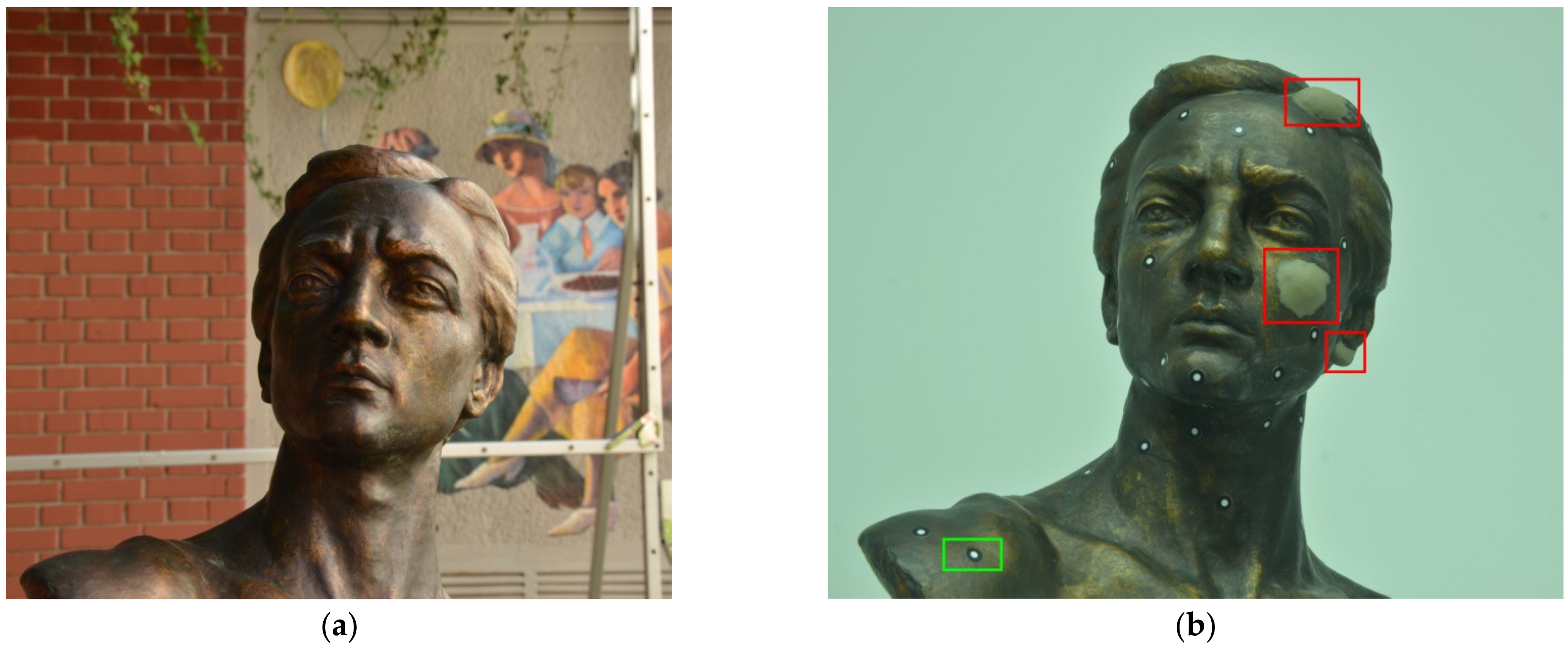
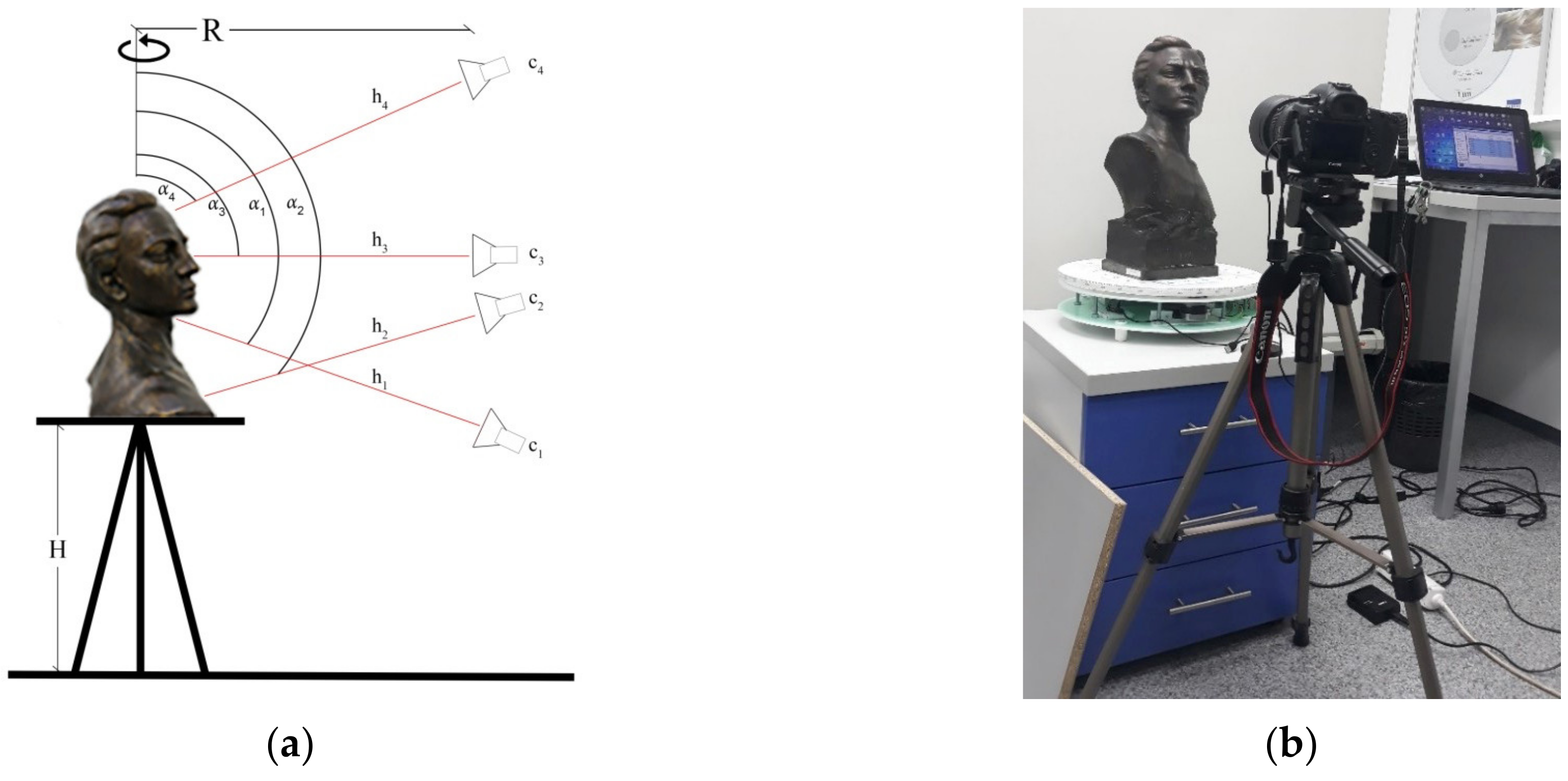
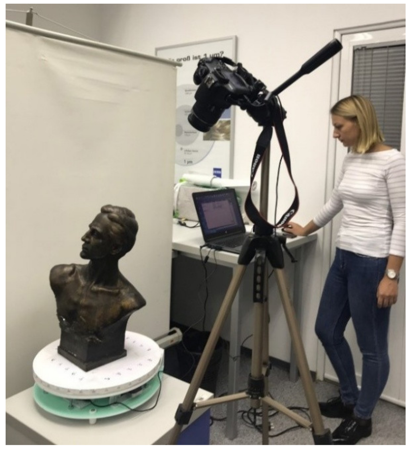
3.2.1. Photogrammetry Surveying

The equipment used for shooting: tripod and NIKON D7000 camera (pixel size—4.78 µm, sensor size—23.6 × 15.6 mm, focal length range—18–109 mm, and crop factor—1.53), with manual settings of the following parameters: f-stop, ISO speed, exposure time.
The selected ground sample distance (GSD) value is 0.1 mm because the 0.1 mm details on the object should be visible. The covered space (D) in the photos is determined by considering the number of pixels of the camera:
D = pixel number × GSD
In that case, the covered space is (0.1 mm∙4928) = 492.8 mm (portrait mode) and (0.1 mm∙3275) = 327.5 mm (landscape mode). Landscape mode was used for the shooting. When GSD was determined, the scale (m) was calculated
m = GSD/(pixel size) = 0.1/(4.78 × 103) = 0.0209 × 10⁻³
and the camera distance from the subject (h) is
h = m × c = 0.0209 × 10−3 × 35 = 0.735 m
where the focal length (c) is 35 mm.
The radial distance from the camera to the sculpture should be the same on all sides. The total circumference of the circle is 2rπ = 2 × 0.735 × 3.14 = 4.615 m, so for a 15° shift, the distance between the photos is the length of the circle tendon b = 19 cm.
The final camera distance was set at 0.5 m, so a compromise was made between field of view (FoV) and depth of field (DoF). To provide the required level of coverage of all surfaces of the sculpture with photographs, the photographs were taken in four different stripes in height, with an increment of 20°. In the face region, the turning increment was less than the predicted 20°. In Figure 2, four camera positions, denoted C1,…, C4 are shown, and the distances along the optical axis from the camera to the sculpture are indicated, respectively, by h1,…, h4. The first stripe is also the lowest stripe in which the camera was placed. The second stripe was set up to photograph the pedestal. At the third level, the camera is positioned at the level of the face with an optical axis of 90° relative to the axis of rotation, and at the fourth and highest level, the camera is positioned above the sculpture, so that the optical axis closed a sharp angle (𝛼4) with the axis of rotation of the turntable. Additional photographs in the region of the face and the crown of the head were taken to gather as much information as possible from the surface of the object. After the photographing, 100 photographs were used to create the 3D model in the AgiSoft Metashape software [71]. The calculated parameters for photogrammetry surveying are shown in Table 1.
Based on the presented shooting plan, the digitized sculpture was photographed in June 2020. The overview of the shooting plan is shown in Figure 2.
Figure 3 shows the interior where the original sculpture was photographed, located in the laboratory at the Faculty of Technical Sciences in Novi Sad. Figure 3 shows the markers positioned on a turntable. These markers create two orthogonal lines, which are coordinate axes in the horizontal plane.
Figure 4 shows the results of the photogrammetric survey. While Figure 4a shows the original model, Figure 4b shows the model with the built-in digital error where the red rectangles indicate the parts of the face to which the clay was added.

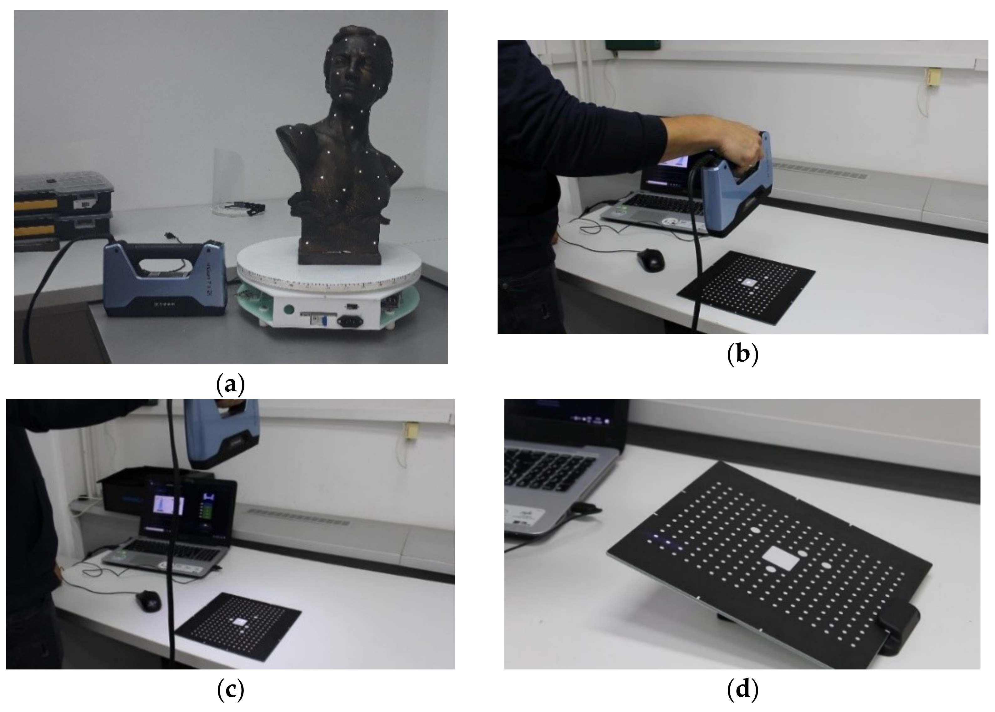
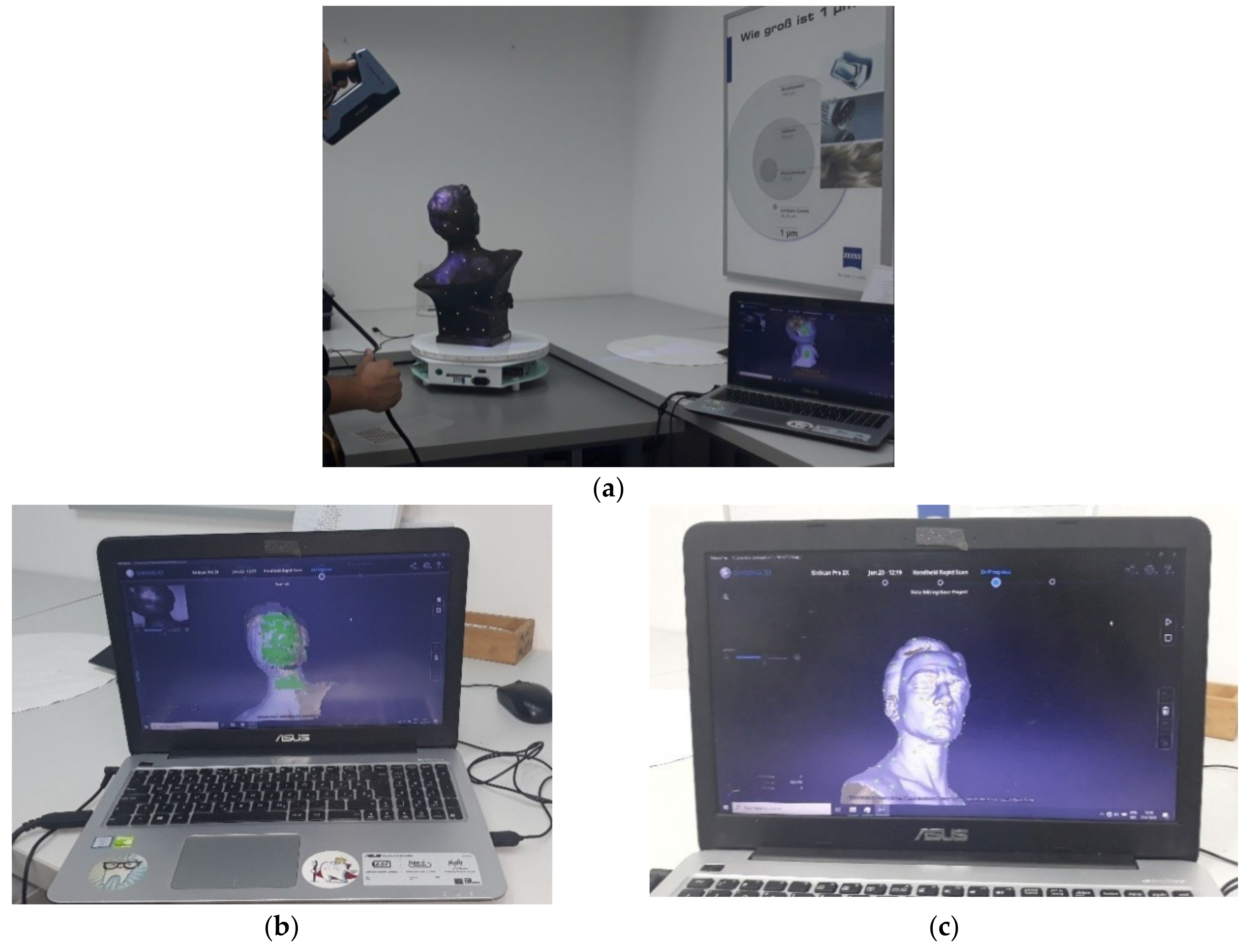
3.2.2. 3D Digitization by Fringe Projection Scanner

The sculpture was scanned using an EinScan Pro 2X scanner. The scanning process was done in the laboratory at the Faculty of Technical Sciences in Novi Sad. EinScan Pro 2X scanner (Figure 5) provides high precision, speed, and ease of use. These scanners have a wide scanning range and can scan all types of objects (small, large, simple, and complex objects).
The precision of this scanner for Handheld HD Scan mode goes up to 0.05 mm [72,73]. The 3D models obtained by using 3D scanners are with high accuracy, but the accuracy and repeatability of the scanner are essential [74]. After connecting the scanner to the computer via USB and starting the software, the calibration process (Figure 5b–d) was performed first. When calibration is finished, the software closes the calibration window automatically and enters the scan mode selection page.
The sculpture was scanned in high resolution where the resolution of the generated point cloud was 0.2 mm. The newly scanned layers were connected and aligned on the basis of markers glued to the sculpture. Before scanning, the markers were glued on the sculpture at random, avoiding gluing in one line. Markers used for this process are professional markers (markers procured from device manufacturers) intended for gluing to objects that are digitized without the possibility of damage during separation or removing. The distance between the scanner and the sculpture was between 350 mm and 450 mm because of the DoF.
Scan results are visible in real-time in the EinScan Pro software in which post-processing of the collected data is performed (Figure 6) [75]. The newly collected point-data is aligned based on the markers, and the new scans are merged with the previous one in the correct way. The newly collected points are marked in green (Figure 6b). In this case, we did not obtain the texture so that only the data about the shape of the sculpture were collected, without color. There are two reasons for that: the first is that we are not interested in texture presentation in this research and the second is that EinScan Pro, which we used, does not have a color (texture) camera.
After the point cloud is collected, a post-processing procedure was done in EinScan Pro software. EinScan Pro is software that is compatible with the EinScan 2X Pro scanner. In the software, most of the options are automatic. Therefore, mesh creation and its optimization were done automatically with a selected level of mesh quality. High quality was selected.
A sculpture with added clay masses was scanned in the same way.
Figure 7 shows the results obtained by 3D scanning. While Figure 7a shows the original model, Figure 7b shows a model where the added clay details are marked with red rectangles.

4. Results

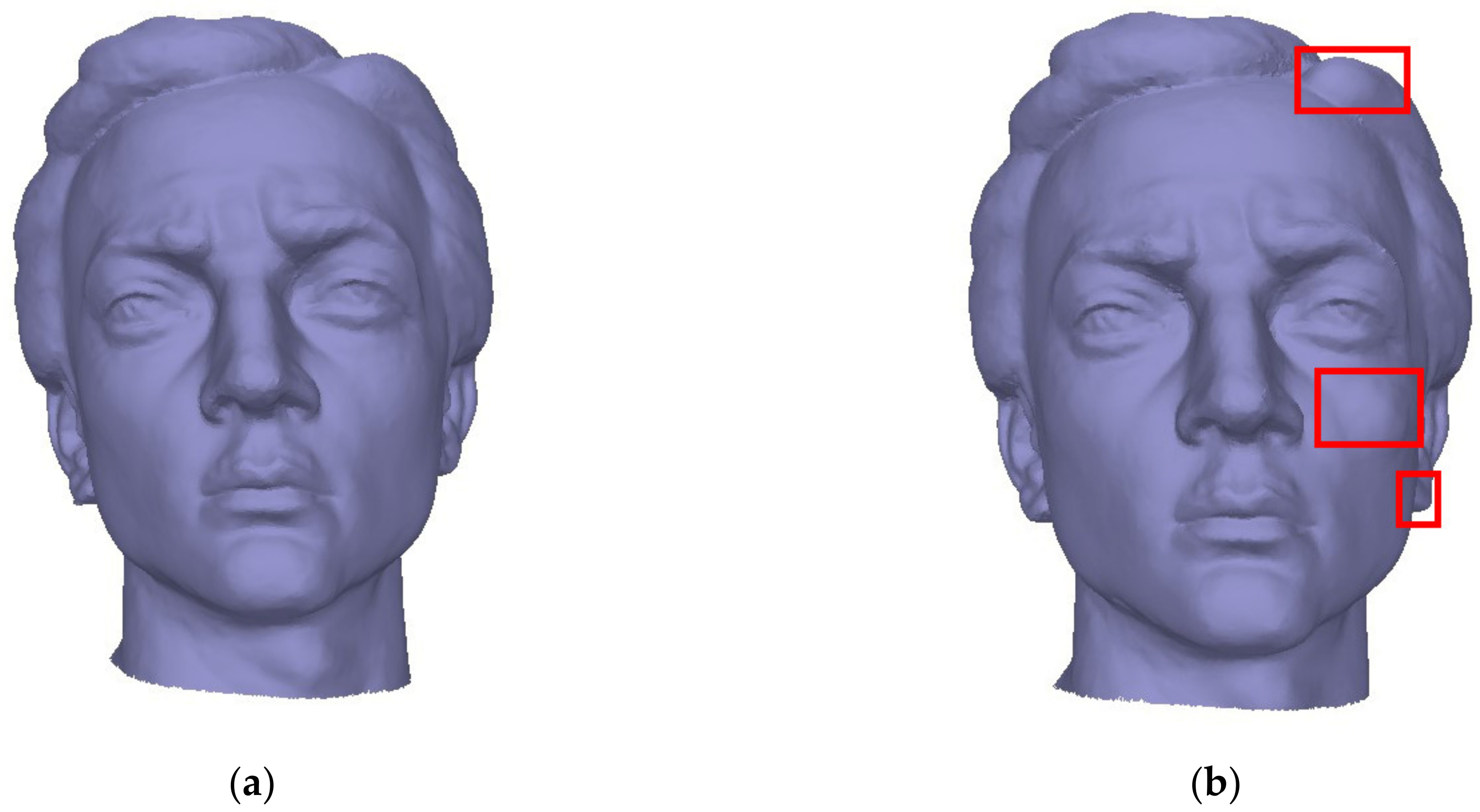
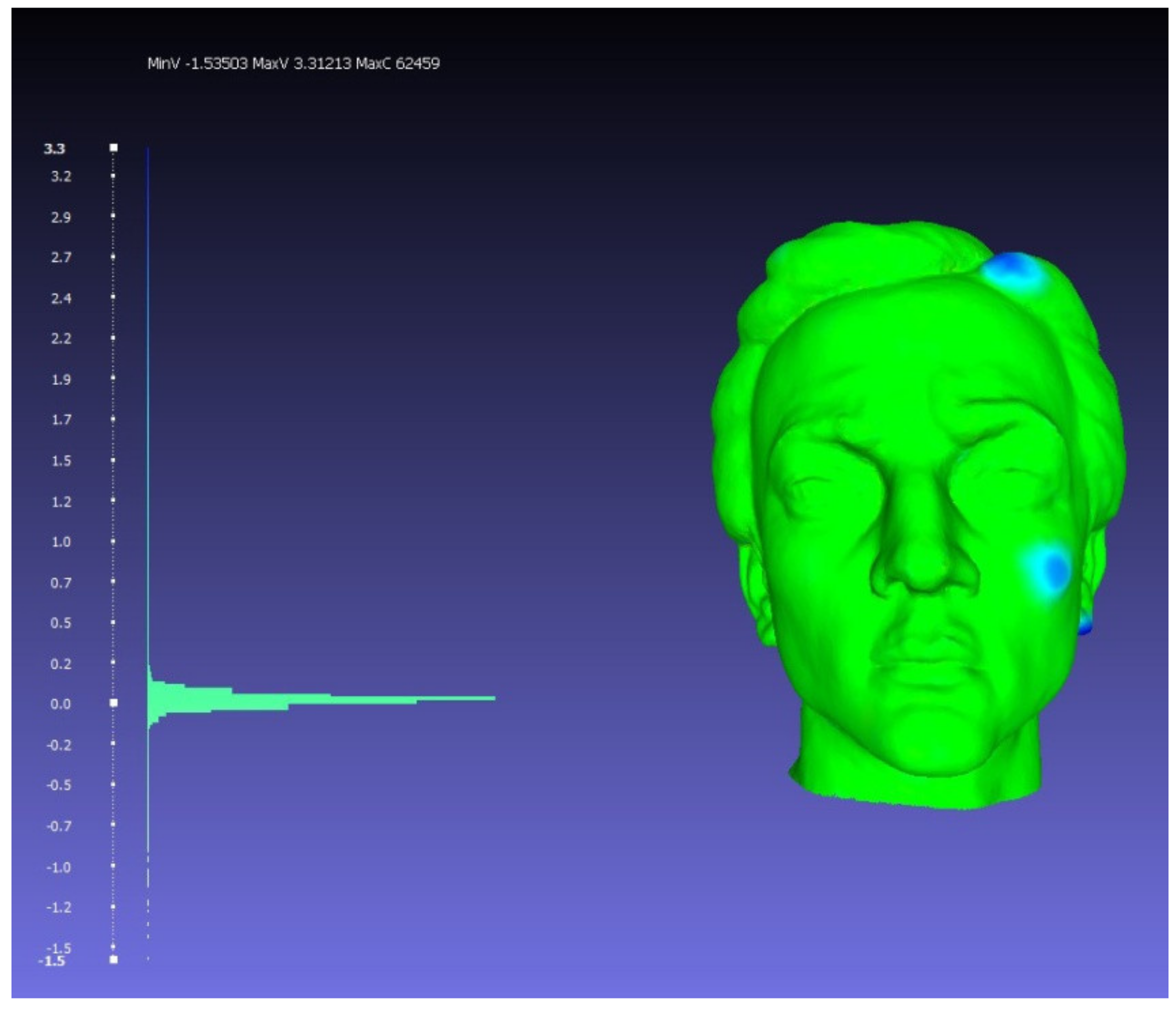
4.1. Comparison of the Geometry of Models Obtained by Scanning in MeshLab Software

MeshLab was used for the comparison of geometrical details of two obtained models—the original model and the model with digital error (using 3D laser scanning technique). It can be noticed that 3D models obtained by photogrammetry are visually rougher compared to the 3D models obtained by scanning, and that is the reason for using 3D models obtained with 3D scanning for analysis in MeshLab and survey. The reference mesh was the mesh obtained from the sculpture without the added clay details. Both meshes were imported and aligned in MeshLab to process the quality control of the details on the mesh with a digital error in comparison with the referent original 3D model of the sculpture. The original and the model with the digital error were compared in MeshLab by calculating vertex geometric distance between them, using the filter named Distance from Reference Mesh.
First, both models (the original model and the model with a digital error) were imported into MeshLab software (Figure 8).
When the models were imported, in order for their geometry to be compared, it was necessary to align their positions and orientations. This step was done using the Align option in the MeshLab software. In this/our case, the reference model is the model obtained by digitizing the original sculpture and the position, and orientation of the second model is aligned with the reference model. When the mentioned model was declared the reference model, and the option of aligning the model based on key/reference points was chosen, it was necessary to set key points on both models (Figure 8b). The key points are placed on the characteristic parts of the face. The reference points must not belong to the “sculptural error” zones. It should be emphasized that the points on the basis of which the alignment of the model is made are arbitrarily set/chosen by the user and that the precision and accuracy of the final result depends on the accuracy of the given positions of the same points on both models. The software recognizes key points and performs their pairing on the models based on the index, that is, the ordinal number of the point according to which they are assigned on the model. For example, if a point with index 0 is in the middle of the upper lip on the reference model, the point with the same index must also be in the same position on the model being compared to the reference, as shown in Figure 8b. The process of setting key points is done manually.
After the key points are set on both models, they are aligned by calling the Process option. The aligned models are shown in Figure 8c.
After the models have been aligned, they are compared, i.e., the vertex geometric distance between them is measured using the Distance from Reference Mesh filter. This filter is automatic and determines the vertex geometric distance on both concave and convex parts of the model geometry. To visually represent the difference/error measured using the Distance from Reference Mesh filter, another filter was used in the MeshLab software. This is called Colorize by Vertex Quality, where vertex quality represents the value of the measured geometric distance and based on that value (depending on whether it is positive or negative), the model is colored with the appropriate color. The results of the model comparison are shown in Figure 9.
The result of the vertex quality for the meshes obtained using the 3D scanning technique is illustrated as the visual representation of the values in Figure 9. The visual representation of the histogram values shows that the details on the models mostly match and do not differ as is illustrated by green values. The green values in the histogram show that the deviations between the compared models are in the interval (−0.1, 0.2) mm; with the deviation equal to zero, there are the largest number of points. The maximal deviation between the models (based on the vertices distance) is about 3 mm, in particular, −1.5 mm for the concave parts of the model, and 3.3 mm for the convex parts. The deviation on the convex parts is represented by blue values and it can be seen that it is located in the parts where clay masses were added to the sculpture.
The results of the comparison of the sculptures obtained by scanning with structured light are real and amount to a few mm, which corresponds to the amount of clay added by the sculptor. Three zones where the sculptor added clay are marked in blue, and there the deviations between the vertices are about 3 mm. The results show that this technique of comparative analysis of 3D models realistically shows the corrections made on the model. Moreover, our analysis presented in Section 4.2. has shown that both surface and point comparison software, MeshLab and CloudCompare, give similar results. We used MeshLab and CloudCompare software for comparative analysis of the obtained results (3D models and point clouds). Our intention was to compare both, the geometry and the point clouds. MeshLab is a software specialized for geometry (mesh) comparison, and we wanted to measure and check deviations on one example of geometry comparison. In the CloudCompare software, the comparison and measurement of deviations on point clouds are measured on all generated point clouds.

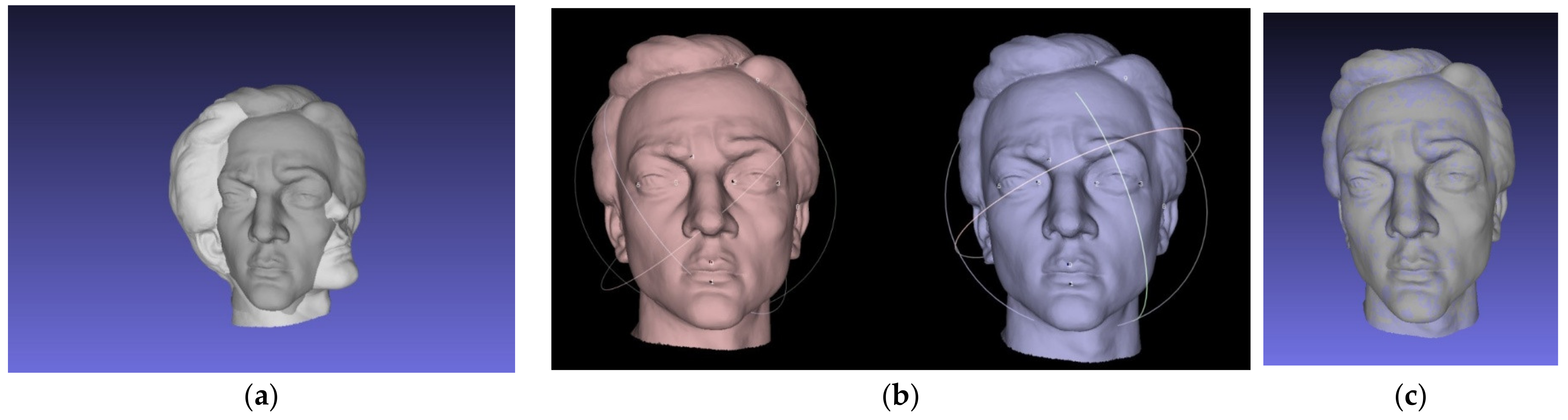
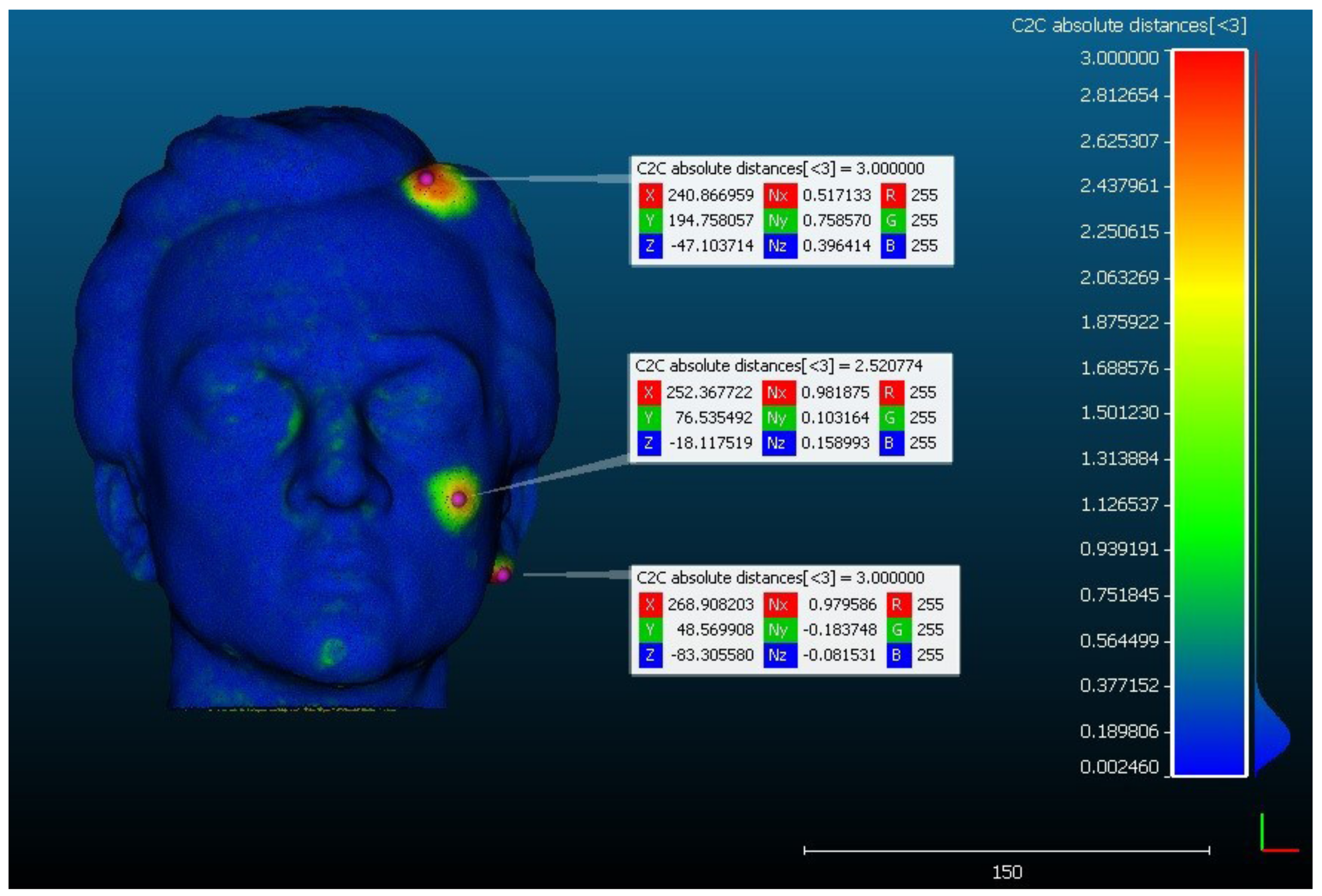
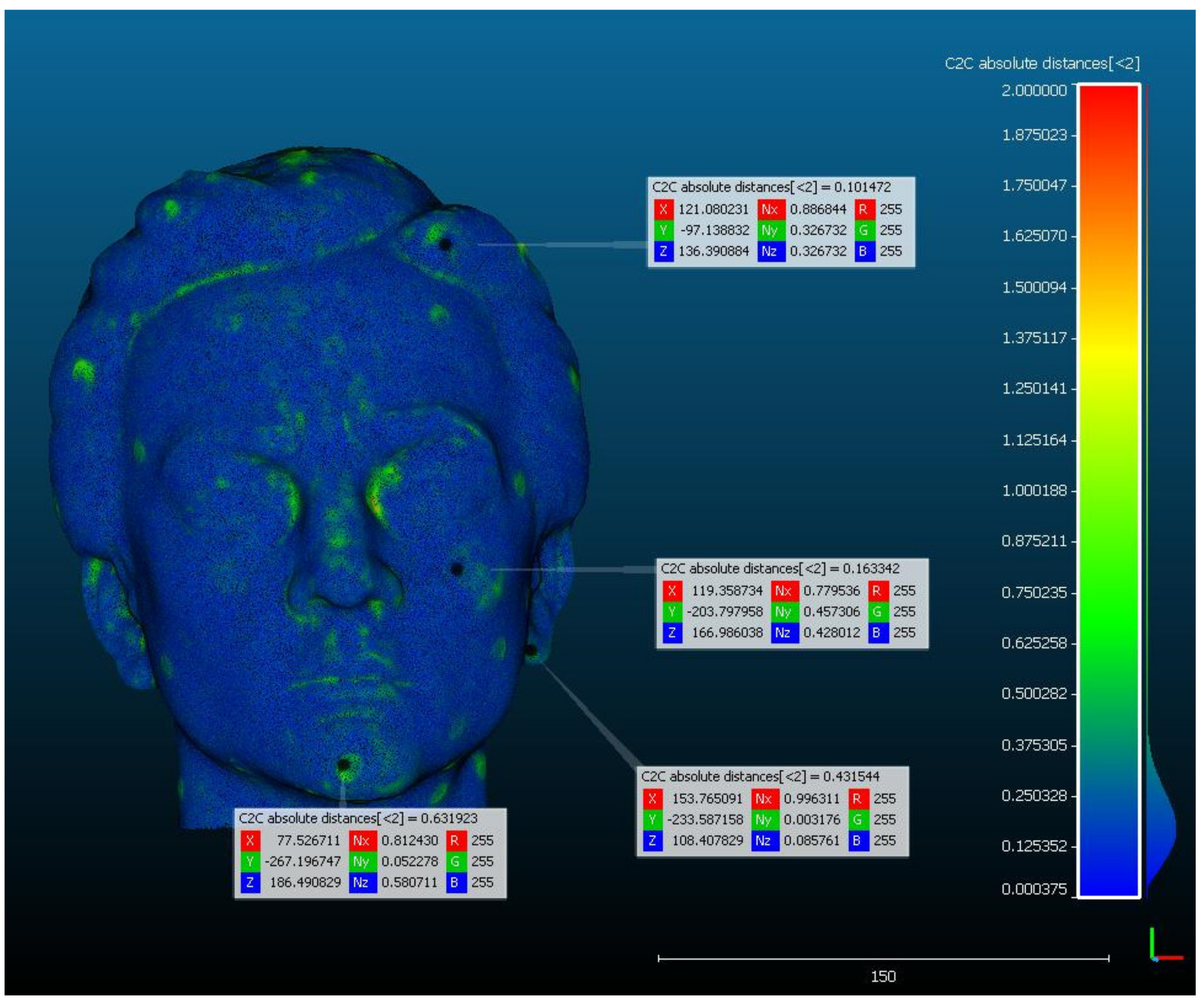
4.2. Comparison of Model Geometry Obtained by Photogrammetry and Scanning in CloudCompare Software

We used two techniques to digitize the sculpture: photogrammetry and structured light scanning. In the first case, the original sculpture obtained by photogrammetry was compared with the sculpture with a built-in error that was also digitized by photogrammetry; in the second case, the original and the sculpture with a built-in error were compared when both 3D models were obtained by scanning; in the third case, the original sculpture whose 3D models were obtained in two ways, by photogrammetry and scanning, was compared; in the fourth case, a sculpture with a built-in error whose 3D models were obtained by photogrammetry and scanning was compared. The comparison in CloudCompare software was done using iterative closest point (ICP) algorithm for aligning. The iterative closest point (ICP) algorithm is a method for aligning point clouds that does not require the corresponding elements and has high accuracy [76,77]. When the point clouds are aligned, the distance of the characteristic point of the model is measured, which is compared in relation to the corresponding point on the reference model.

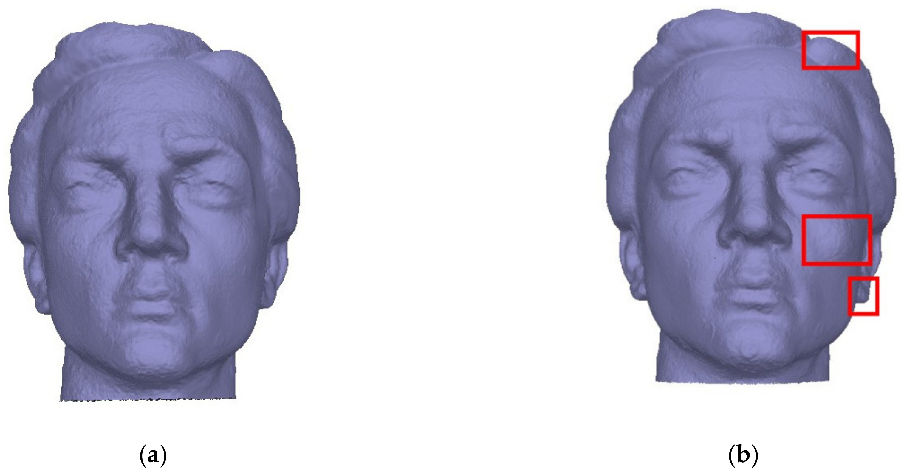
4.2.1. The Original and the Model with Error Obtained by Photogrammetry

Figure 10 shows the results obtained by photogrammetry (original model and 3D model with digital error). The reference model is the original 3D model, while the model being compared is the digital error model. A comparative analysis of these two models estimated that the absolute deviation has a value of 3 mm (values marked in red). The points that have the largest deviation value (3 mm) are the least numerous, as can be deduced from the figure. The points that have the largest deviation from the reference model are located in the areas where clay was added to the sculpture, and in these areas, the values of the coordinates of the three points are analyzed with the distance from the points on the reference model found to be 3 mm, 2.520 mm, and 3 mm, respectively. Most of the points have a deviation between 0.2 mm and 0.3 mm and these are the values that are colored blue on the histogram.
For each selected point, the (X, Y, Z) coordinates are shown; Nx, Ny, and Nz show the projections of the unit vector of the normal of the observed point on the axes of the XYZ coordinate system. Each component of the RGB model is in the range 0–255. The colors of the area on the point cloud correspond to the colors on the histogram. The deviation value on the histogram is shown on the vertical axis, while the horizontal axis on the right side of the histogram shows the number of points with that deviation. The value of the average deviation is 0.029 mm, while the standard deviation of the model with digital error is 0.235 mm.

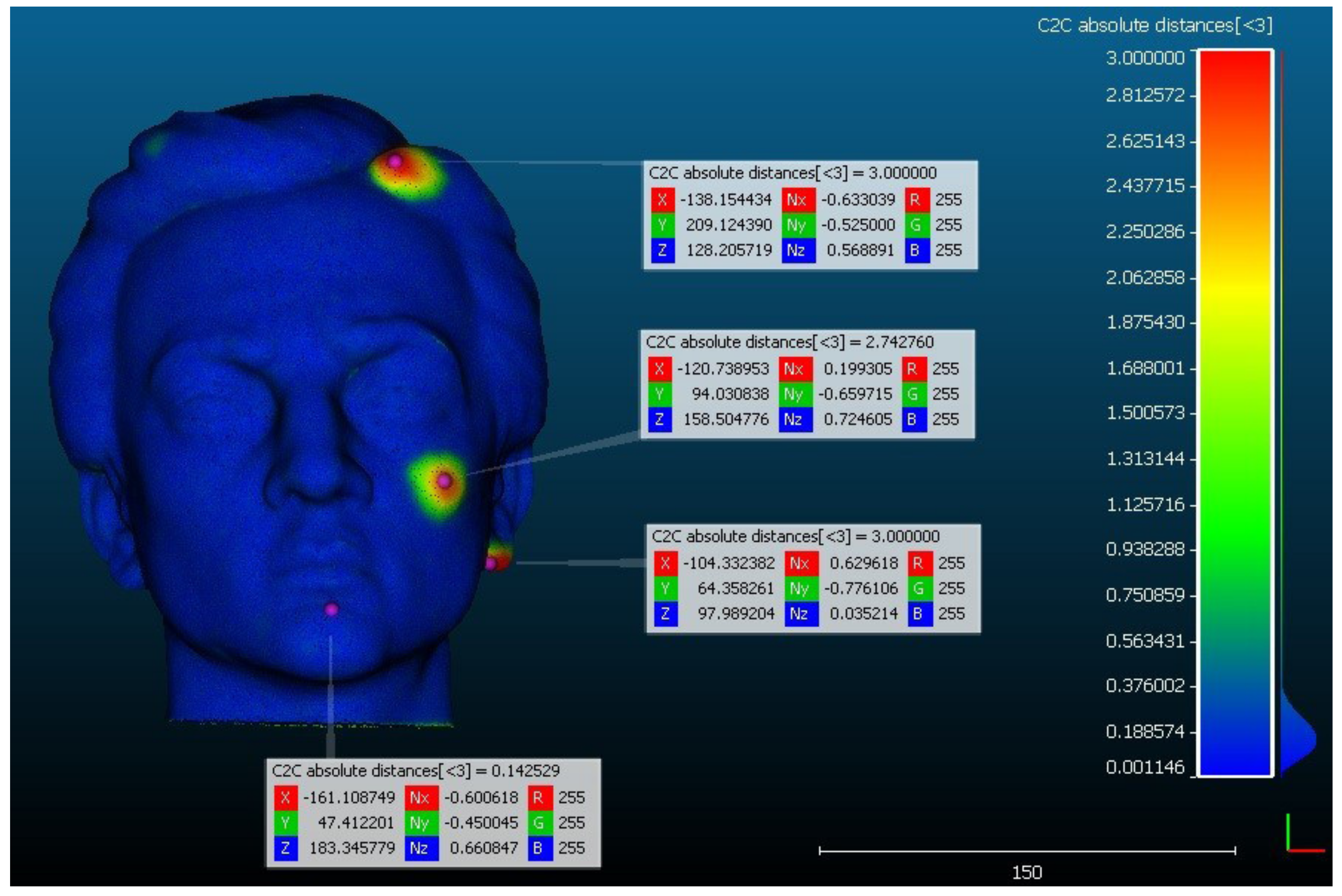
4.2.2. The Original and the Model with Error Obtained by Scanning

Figure 11 shows the results obtained by 3D scanning (the original model as reference model and the 3D model with a digital error). By comparative analysis of these two models, it was estimated that the absolute deviation has a value of 3 mm. The points that have the largest deviation from the reference model are located in the areas where clay was added to the sculpture, and in these areas the values of the coordinates of three points and the distance from the points on the reference model are 3 mm, 2.742 mm, and 3 mm, respectively. Most of the points have a deviation between 0.1 mm and 0.2 mm. The value of the average deviation is 0.025 mm, while the standard deviation of the model with digital error is 0.226 mm.

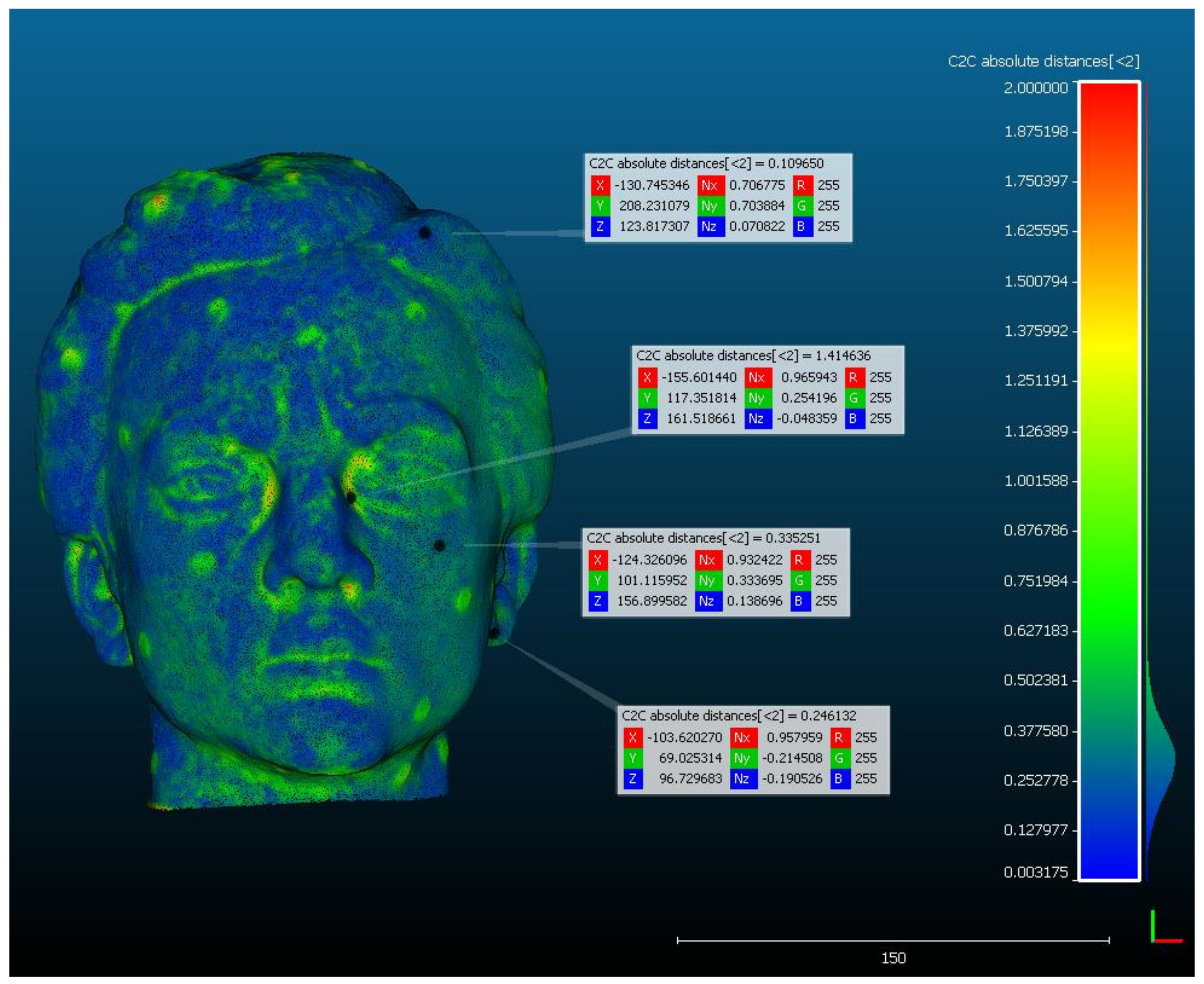
4.2.3. Comparison of Original Models Obtained by Scanning and Photogrammetry

Since the models were obtained by different digitization techniques, photogrammetry, and 3D scanning, the obtained results were analyzed, i.e., comparative analysis of the original model obtained by scanning and the original model obtained by photogrammetry determined the values of deviations between these two models. In this case, the reference model is the original model obtained by scanning. The results of the analysis shown in Figure 12 indicate that the absolute deviation has a value of 2 mm. One point (on the right corner of the left eye) was singled out from the area with the largest deviation (area with points marked with orange color), and the deviation for that point is 1.414 mm. The points on the parts of the face on the left side (ear, cheekbone, hair) have deviations of 0.1097 mm, 0.335 mm, and 0.246 mm, respectively.
The largest number of vertices are in the blue and green zones, where the deviations are approximately between 0.1 and 0.5 mm. It is obvious that the techniques we used, scanning and photogrammetry do not lead to absolutely the same models, as expected. We used both techniques with the aim to come to the conclusion which technique is more optimal for use in the specific case of digitization of sculpture. The value of the average deviation is 0.064 mm, while the standard deviation of the model with digital error is 0.335 mm.

4.2.4. Comparison of the Model with Digital Error Obtained by Scanning and by Photogrammetry

The comparative analysis of the model with a digital error obtained by scanning and the model with a digital error obtained by photogrammetry determined the values of deviations between these two models. In this case, the reference model is the model obtained by scanning. Figure 13 shows the obtained results. By analyzing these two models, it was estimated that the absolute deviation has a value of 2 mm. One point (on the chin) was singled out from the area with the largest deviation, and the deviation for that point is 0.631 mm. The points on the parts of the face on the left side (ear, cheekbone, hair) have deviations of 0.101 mm, 0.163 mm, and 0.431 mm, respectively.
The histogram shows that the largest number of vertices between the two analyzed models have a deviation in the interval 0.0004–0.4 mm. The value of the average deviation is 0.015 mm, while the standard deviation of the model with digital error is 0.180 mm.
Based on the presented results, it can be concluded that both techniques, i.e., photogrammetry and scanning, recognize the parts of the sculpture where clay masses have been added. It can be noticed that the 3D models obtained by photogrammetry are visually rougher compared to the 3D models obtained by scanning. For the photogrammetric survey, the dark and uniform texture without many features is not suitable for data processing in the software we used for photo processing. For that reason, a photogrammetric survey has resulted in the 3D models of sculptures with a noticeable surface roughness of the model, which is the consequence of the inability of the software to find a larger number of reference points in the photographs. On the other hand, shooting with structured light, in addition to being a cheaper time procedure, in this case also led us to a 3D surface that is smoother compared to the photogrammetric model. All four models have about 300,000 points and about 550,000 polygons. Due to the difference in surface fineness, for further work on the project and a survey of a group of 195 subjects, we used models obtained using structured light.
In any case, the obtained results are satisfactory in the sense that the errors occur only in the parts where we assumed that they would occur. The error/difference between the obtained models of these dimensions is not visible to the average observer. Based on these results of comparing the original with the model with a digital error, we can conclude that 3D scanning is a more favorable technique in the case of a smaller object such as a sculpture [78,79].

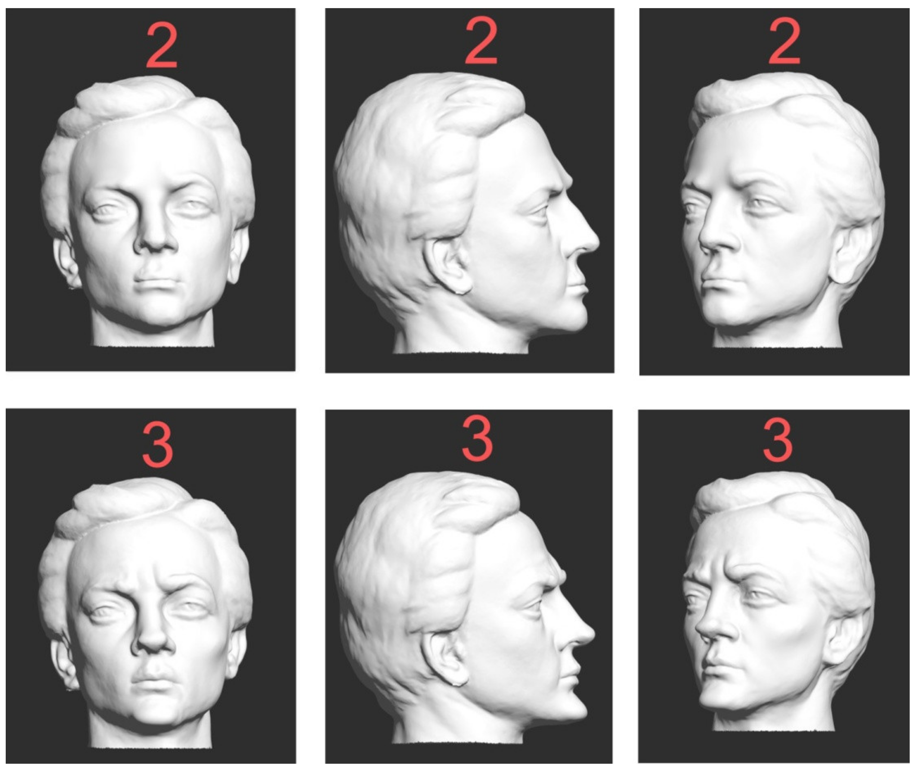
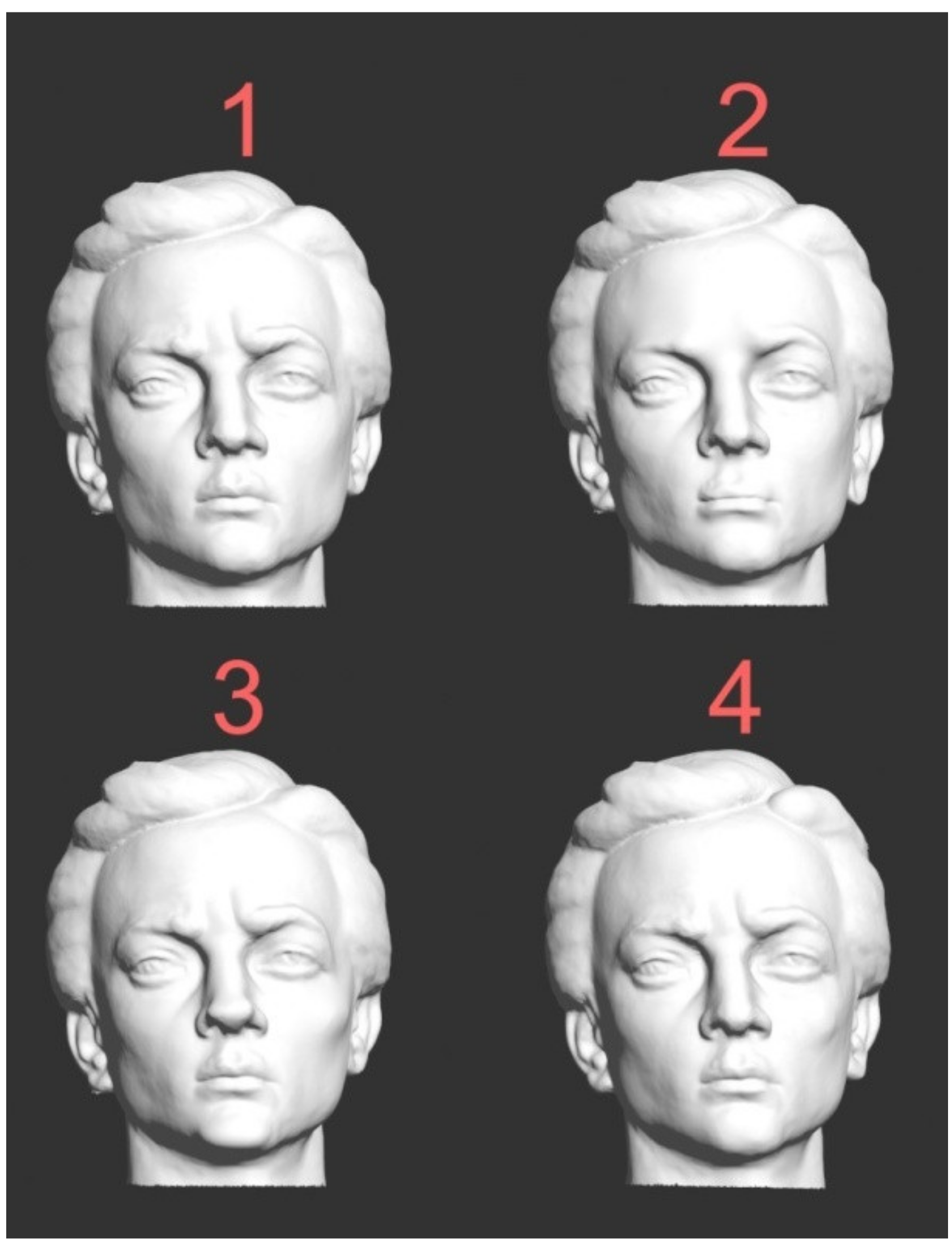
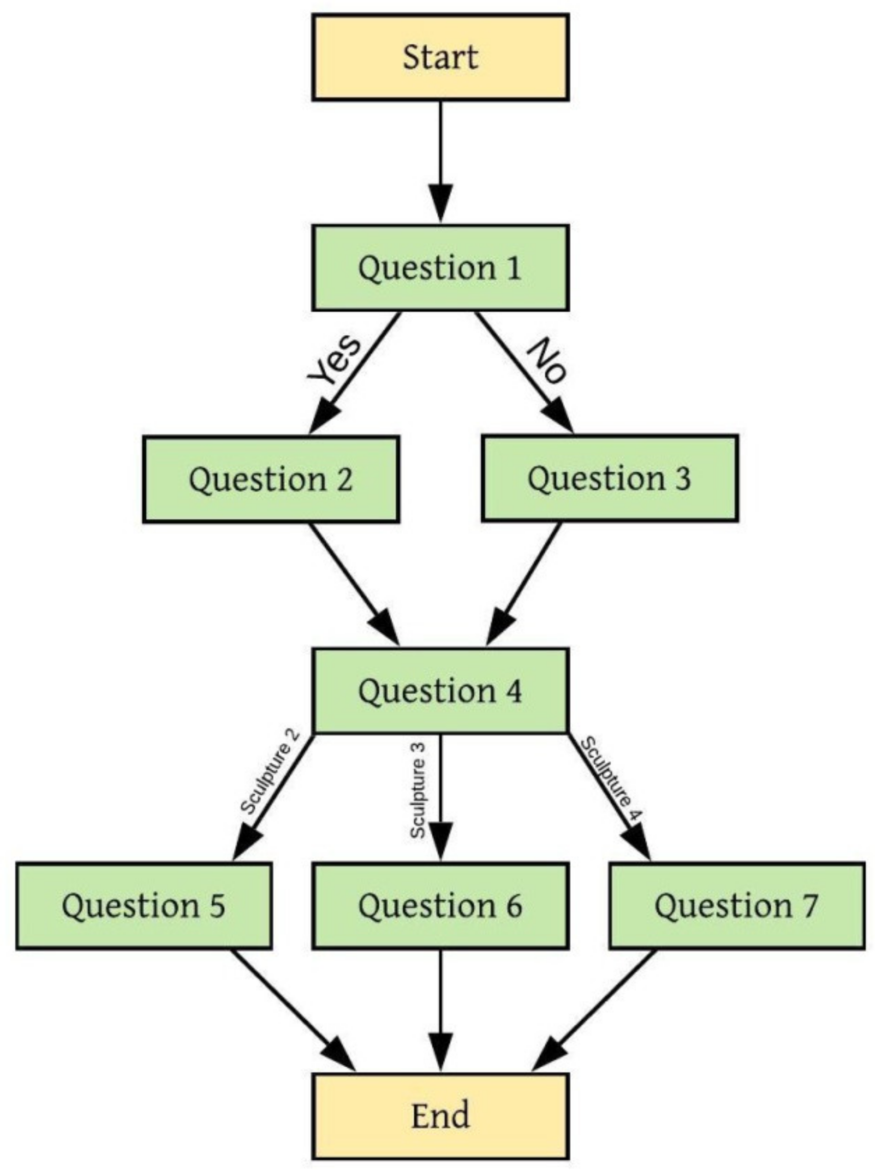
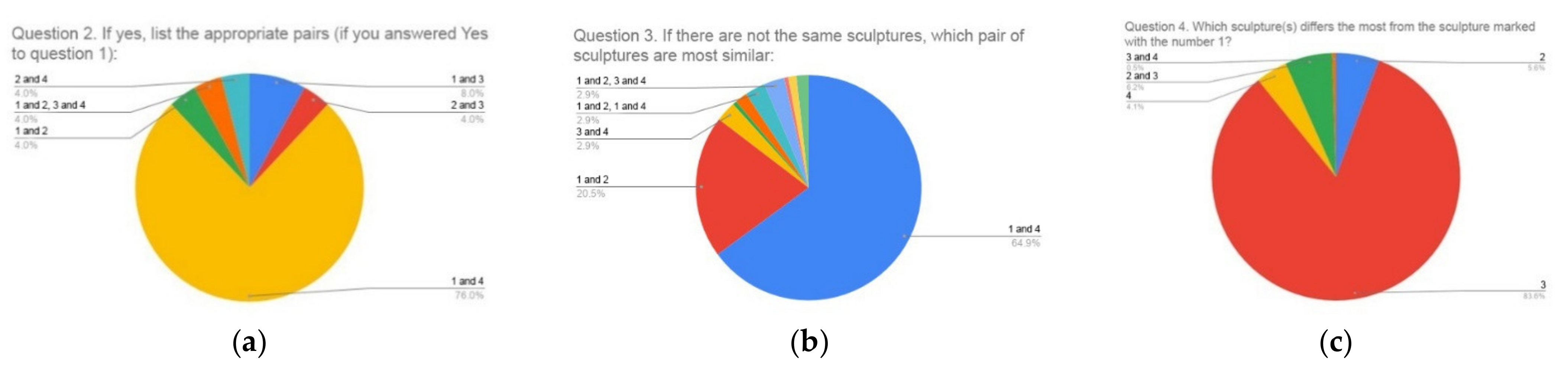
4.3. Survey on the Geometric Similarity of Sculptures

Our research also included a survey conducted with 166 students studying at the Faculty of Technical Sciences, the University of Novi Sad, of which 94 were students of Computer Graphics (students of all five-year undergraduate and master studies) and 72 first-year students of mechanical engineering (ME). These students were selected as a suitable group for research because of their orientation toward visual and spatial presentation and 3D modeling. In addition to students, another 29 persons (Others) who were not students and did not study computer graphics or some other related field were surveyed, so that a total number of respondents was 195. For the purposes of this test, two more variants (2 and 3 on Figure 14) of the sculpture used in this research were created, and geometric modifications were built into the new variants of the model in the Zbrush software, which is specialized in digital sculpting. These deformations are added so that they are relatively easy to see visually (Figure 14).
The created composition consists of four sculptures arranged in two rows (Figure 15). The original sculpture is shown in position 1, and the sculpture with the digital protection is shown in position 4, while the sculptures that are deformed in Zbrush (from Figure 15) are shown in positions 2 and 3.
To obtain a spatial representation of these sculptures, a Turntable video (360 degrees) was created in which all sculptures rotate simultaneously and at the same speed, each around its vertical axis [80]. On the other hand, the position of the camera is fixed and it captures all four figures at the same time. Each respondent was able to see the video multiple times and pause it at any time. The video lasts 15 s, and during that time, each sculpture is rotated at the same speed by 360 degrees. We considered this to be an acceptable speed of rotation that allows any observer to spot details on the sculptures. After watching the video, respondents completed a survey consisting of seven questions, and the results were processed using Google Forms. The questions are:
1.
Are there two identical sculptures? a. Yes, b. No
2.
If you answered Yes on question 1, list the appropriate pairs:
a. 1 and 2 b. 1 and 3 c. 1 and 4 d. 2 and 3 e. 2 and 4 f. 3 and 4
3.
If there are no sculptures that are the same, which pair of sculptures is the most similar:
a. 1 and 2 b. 1 and 3 c. 1 and 4 d. 2 and 3 e. 2 and 4 f. 3 and 4
4.
Which sculpture(s) differs the most from the sculpture marked number 1?
a. 2 b. 3 c. 4
5.
If you mentioned sculpture 2 in the previous answer (Question 4), list the parts of the face on sculpture 2 that are different from sculpture 1:
a. Beard b. Mouth/Lips c. Nose
d. Left cheekbone e. Right cheekbone f. Left eye
g. Right eye h. Lower jaw bone i. Arcade/protrusion of the frontal bone on the left side
j. Arcade/protrusion of the frontal bone on the right side k. Forehead l. Hair
m. Earlobe on left ear n. Earlobe on right ear o. Left ear
p. Right ear
6.
If you mentioned sculpture 3 in the previous answer (Question 4), list the parts of the face on sculpture 3 that are different from sculpture 1:
The answers offered are the same as for Question 5.
7.
If you mentioned sculpture 4 in the previous answer (Question 4), list the parts of the face on sculpture 4 that are different from sculpture 1:
The answers offered are the same as for question 5.
Each respondent answered four of the seven questions. The combination of questions is not the same for all respondents and depends on the answers to the first and fourth questions. Figure 16 shows a block diagram with different combinations of questions. Questions 2–7 could have multiple answers. The survey was conducted in April 2021.
The first column in Table 2 shows the groups of respondents, where the students are grouped according to their years of study and profile. The students’ years of study were considered important because we felt that older students who have more experience with visualization and 3D presentations would be better observers. On the other hand, we also included a group of people who have no relation to this field because we wanted to get answers from average observers. The second column gives the numbers of respondents, the third column shows those respondents who answered Yes to the first question, and on the second question answered that sculptures 1 and 4 are identical. The fourth column gives the respondents who answered No to the first question and on the third question answered that sculptures 1 and 4 are the most similar. In the next three columns are the numbers of respondents who, in answer to question 4, stated that in relation to sculpture 1, the sculpture that differs the most is 2, 3, or 4, respectively.
When the results are summarized, the following can be noticed: in answer to the first question, 86.7% of the respondents answered that no two sculptures are the same, and 13.3% that they are the same sculptures. Of this 13.3%, 76% answered that sculptures 1 and 4 are the same (Figure 17a).
Of the 86.7% of the respondents who answered No to the first question, 64.9% of them answered in question 3, that sculptures 1 and 4 are the most similar (Figure 17b).
Question 4 was answered by all respondents (Figure 17c), and the question was Which of the three sculptures 2, 3, 4 is the most different from sculpture 1?
The graph shows the numbers of sculptures and the voting percentages of the respondents, with some respondents saying that the two sculptures (choosing between 2, 3, and 4) are significantly different from sculpture 1 (combinations 2 and 3, and 3 and 4, respectively). Dominantly, 83.6% of respondents noticed that sculpture 3 differs the most from sculpture 1, which is the correct answer. We should repeat here that we got sculptures 2 and 3 from sculpture 1 by moving the knots randomly, and those deformations were larger than in sculpture 4 (which we formed in cooperation with the sculptor).
The first three columns show us that the students of higher years of study (IV and V) were better at noticing the differences between the sculptures. Thus, fifth-year students saw that sculptures 1 and 4 were the same or the most similar in 100% of cases (100% × (1 + 7)/8). For fourth-year students, the success rate is 76.7% (100% × (3 + 20)/30), while for third-year students, the success rate is 72.2%. Second-year students had a success rate of 63.6%, and first-year students had a success rate of 56.3%. First-year mechanical engineering students had a 68% success rate, while people in the group Others had 79.3%. The majority of respondents from the Others group (86%) have a university education of various orientations.

4.4. Digital Protection Extraction

Figure 10, Figure 11, Figure 12 and Figure 13, which show the results of the comparison of the original model and the model with an added digital error (protection), indicate that differences were detected between the mentioned models. These differences appear on the parts of the sculpture to which the digital protection has been added: a lock of hair (on the left), the earlobe (on the left), and the cheekbone (on the left). The obtained results clearly indicate that by comparing the original model and the protected model, it is easy to determine the appearance and dimensions of the digital protection added to the original model. It is also easy to check and prove the originality of the 3D model, i.e., its copy if it is misused. Using the Boolean operation subtraction, it is easy to extract the digital protection from the model to which it was added and archive it as such. Subtraction operation involves subtracting the geometry of the 3D model of the original sculpture from the geometry of the 3D model of the sculpture with a protection, where the resulting protection is obtained. This operation is available as an option in most 3D software. One such software is 3ds Max, which we used for the protection extraction process.
Then a model with added clay details was selected and the Boolean option was added to it, which means that the software automatically recognized that the geometry of the next selected model would be subtracted from the geometry of the protected model (Boolean→Subtraction option). In this case, the original 3D model was subtracted. Since the geometries of these two models differ only in places where clay was added as tested in MeshLab and CloudCompare software, the Boolean subtraction operation resulted in a geometry representing the pieces of clay added by the sculptor to the original sculpture before its digitization, and this is actually our digital protection shown in Figure 18, highlighted in red.

5. Discussion

This paper analyzes the possibility of protecting a digitized sculpture using a new approach. Clay was added to the sculpture at locations selected by the sculptor. Then, the original sculpture and the sculpture with added clay were digitized in two ways, using photogrammetry and 3D scanning.
By comparing the results obtained by photogrammetric surveying and scanning of the sculpture with structured light, when determining the error between the original and models with embedded digital protection, we came to the conclusion that this error is visually equally noticeable in models obtained using both 3D digitization techniques. This shows that photogrammetry and structured light can be used to analyze the comparison of the two models, but in this case when comparing a smaller object such as a sculpture, it is better to use 3D scanning because the result is a sculpture with fewer irregularities on the surface, as other authors have previously concluded. When comparing the models obtained by photogrammetry and scanning, the situation is real because all three places where clay was added are noted, and the measures of the added material in both cases correspond to the real situation.
As part of this research, a survey of 195 subjects was conducted where four sculptures were observed, an original 3D model (sculpture 1), a model with a digital error (sculpture 4), and two more 3D models (sculptures 2 and 3) obtained by deformation of the original model in Zbrush software (Figure 15). However, the survey used a 3D model obtained by 3D scanning because its surface is smoother. For research purposes, a turntable video was created in which these four sculptures rotate simultaneously, each around its own vertical axis, and based on that, a seven-question survey was conducted. Of the total number of respondents, 13.3% claimed that there were two identical sculptures, and of that 13.3%, 76% claimed that sculptures 1 and 4 were the same. Moreover, out of the total number, 86.7% of the respondents said that there were no two identical sculptures, and out of that number, 64.9% noticed that sculptures 1 and 4 are the most similar. In both groups (13.3% and 86.7%), it was predominantly observed that sculptures 1 and 4 were the same or most similar. This result shows us that the digital error created in collaboration with the sculptor was introduced with a measure that is difficult to visually notice. It is much easier to notice an error that is obtained by moving the vertex in a 3D software without an adequate strategy. Our strategy was that the sculptor would add a protection that would be difficult to notice visually.
The answers of the respondents fulfilled our expectations because they noticed that the most similar sculptures are the original and the sculpture with a digital error, which corresponds to the real situation. The basic idea of this research is to make a 3D model with a digital error available to the public, while the original 3D model is hidden from the public. The average observer will not be deprived of their artistic experience of the sculpture because they are not even aware that it has been minimally altered in relation to the original, and the owners of the sculpture are thus protected from the potential abuse of their work.
Additionally, our intention was to present to the general public a 3D model of the sculpture that is very similar to the original, but that is not the original. In that way, the observers of this model would not be deprived at all of the artistic experience of the observed work of art. The other advantage of this approach is that there is no possibility of abuse of the original work of art. If someone takes the 3D model of the sculpture that we have given for public inspection, and prints that model on a 3D printer, we could easily prove that such a sculpture is a forgery. We would achieve this by scanning a printed sculpture and comparing such a 3D model with our original model. The result would be the difference between these models, which is a protection that we added in collaboration with the sculptor. Another level of protection is that we would not place the original 3D model of sculpture on a server that also has a sculpture with a digital error, nor would we in any way make the original 3D model available to the public.
In this research, we did not deal with the error that occurs during 3D printing and data transfer from a 3D digital model to a 3D printed model. The accuracy of the scanner and the resolution (point distance) should be such as to enable 3D digitization of all details that are important for a quality visual presentation of the sculpture, i.e., added protective errors. In case it is planned to make a replica with an error using a 3D printer, it must have the accuracy and resolution that allow the production of the finest details. However, we will briefly look at the topic of accuracy in 3D printers.
Despite the rapid growth of 3D printing techniques, the accuracy of 3D printed models has not been thoroughly investigated [81]. The deviation of the dimension of the 3D printed model from the dimension 3D digital model represents the accuracy of 3D printing. Dimensional accuracy of 98.81% was achieved for the commercial FDM 3D printers [82]. Various factors affect the accuracy of the printed 3D model; these are temperature on the nozzle, the nozzle thickness, the filament scale, the built-in plate’s temperature, the basis for printing, layer height, infill density, printing speed while printing with pure polypropylene, deformation, filament entry, the flow of material, and the gap between the nozzle and the board [83]. This means that even if the model is digitized with high precision, that precision and level of details can be impaired in the 3D printing process. Dimensional and geometrical deviations that occur on a printed 3D models and the size of the deviations may also depend on the type of file transfer format [84]. A new approach in the field of 3D printing, the so-called powder-based 3D printing has improvements in dimensional accuracy, printing resolution, and production speed. It has the flexibility in designing the complex structure, usage of different materials within a single design, reduced material cost for manufacturing, and on-demand manufacturing of customized products [85]. This approach also has its limitations like higher material cost, longer printing time, laborious post-processing, a thermal distortion that leads to warping, and limited material selection. The new 3D printing technique is color 3D printing, which also has its limitations [86].

6. Conclusions

Although we are aware of the fact that today there are several different techniques for protecting 3D models, the dominant being to create a watermark, we started with a dissimilar approach which is special/different in the sense that each cultural heritage object is seen as a unique object. We have created two 3D models of the sculpture; one is a 3D model of the original sculpture and the other is a 3D model of the sculpture with a built-in error. Both the original sculpture and the sculpture with added 3D segments were digitized by photogrammetry and a 3D scanner based on structured light.
The main idea of our paper is to enable the visibility and artistic experience of sculptures and other artistic artifacts through online access to their 3D models with built-in protection. As these works have great artistic and material value, our approach in a new way enables the protection of the original 3D model from theft or misuse. Namely, we added material to the original model of the sculpture in a couple of places with the help of a sculptor, and then we digitized a sculpture “with an error” again. The error added in this way is discrete and will not diminish the artistic experience of the sculpture, that is, the average viewer will be convinced to observe the 3D model of the original sculpture. Our hypothesis that the 3D model of the original sculpture and the 3D model of the sculpture with the built-in error is the most visually similar was confirmed by a survey of 195 respondents. Only the 3D model of the sculpture with digital error will be exposed to the public, and the original 3D model will be archived. Although this approach requires an individual observation of each work of art, it also offers some advantages. Digitization and protection of models, in this way, can be done by employees in cultural institutions and this approach, where artists are included, is acceptable for experts in the field of art and culture, who do not have adequate knowledge of programming and algorithms, and such knowledge is required when creating a watermark. We believe that this approach can enable mass digitization of works of art, their visibility through 3D models with digital error, and again protection against theft and misuse.
Unlike most works in which the watermark 3D model is added using different mathematical approaches and algorithms, this individual approach to each artistic 3D work can be considered a good solution that enables the presentation of cultural heritage but also preserves it from abuse. The disadvantage of the approach is that each work, i.e., 3D model, requires an individual approach and cooperation of artists and technical staff. Another disadvantage may be that the clay that we applied needs to be removed from the sculpture after shooting. Some materials from which sculptures are made, such as marble, steel, or bronze, can be easily cleaned off the applied clay without damage. Gypsum sculptures, on the other hand, are susceptible to damage during clay removal. Therefore, future research could examine the application of a haptic hand that can be used for digital sculpting. In the haptic hand, the sculptor has realistic resistance in the glove, and this procedure is the most approximate simulation of real sculpting. In digital sculpture, the starting model is a 3D model obtained by digitizing the original sculpture.
We noticed three shortcomings in our procedure. The first is that it is necessary to use the assistance of a sculptor to work with each individual sculpture. Another disadvantage is that, when applying clay to the sculpture, contact is made with the sculpture, and after the digitization of the altered sculpture, it is necessary to remove the added material. During this process of removing the material, the sculpture can be damaged. According to the experience of sculptors from our team, there are clays that are easy to apply but also easy to remove, so it is possible to apply such clay and remove it without damaging the object. The third shortcoming is that the presented method requires scanning each museum object twice, thus doubling the required time and resources. This problem can be solved by using a haptic hand by which a digital error will be added in software on the 3D virtual model.
Possible topics for future work are:
-
Using a haptic hand for digital sculpting. With this device, the sculptor would sculpt on a 3D model that is digital and avoid contact with the original work of art. In this way, we could add a digital error without contact with the original physical model. This would reduce the execution time, i.e., it would be necessary to digitize only the original work (piece of art), not the work with built-in physical error.
-
Determining reference positions for adding a digital error to characters of different years/ages or sex.
-
In this paper, we have limited ourselves to sculpture because we wanted to analyze and confirm that our idea and approach lead to valid results. It is certainly possible to apply the procedure to other types of artifacts, such as coins, pottery, or architectural objects.

Author Contributions

Conceptualization, I.V., R.O. and L.K.; methodology, I.V., R.O., I.B. and I.Đ.; validation, R.O., B.P., Z.M. and I.B.; formal analysis, I.V. and R.O.; investigation, I.V., R.O. and I.Đ.; resources, R.O. and I.B.; software, I.V. and I.Đ.; writing—original draft preparation, I.V., R.O., B.P. and I.B.; writing—review and editing, R.O., B.P., Z.M. and I.B.; visualization, I.V., R.O., L.K. and I.Đ.; supervision, R.O., B.P., Z.M. and I.B.; project administration, I.V. and R.O.; funding acquisition, R.O. All authors have read and agreed to the published version of the manuscript.

Funding

This research received no external funding.

Institutional Review Board Statement

Not applicable.

Informed Consent Statement

Not applicable.

Data Availability Statement

Not applicable.

Acknowledgments

This research is partially supported by the Ministry of Science and Education of the Republic of Serbia, Grant 451-03-9/2021-14/200105 05.02.2021.

Conflicts of Interest

The authors declare no conflict of interest.

References

  1. Djuric, I.; Stojakovic, V.; Misic, S.; Kekeljevic, I.; Vasiljevic, I.; Obradovic, M.; Obradovic, R. Church Heritage Multimedia Presentation-Case study of the iconostasis as the characteristic art and architectural element of the Christian Orthodox churches. Architecture in the Age of the 4th Industrial Revolution. In Proceedings of the 37th eCAADe and 23rd SIGraDi Conference, University of Porto, Porto, Portugal, 11–13 September 2019; Volume 1, pp. 551–560. [Google Scholar] [CrossRef]
  2. Koller, D. Protected sharing of 3D models of cultural heritage and archaeological artifacts. In Proceedings of the 36th CAA Conference, Budapest, Hungary, 2–6 April 2008; Volume 2, pp. 326–331. [Google Scholar]
  3. Obradović, R.; Stojaković, V.; Đurić, I.; Vasiljević, I.; Kekeljević, I.; Obradović, M. 3D Digitalization and AR Presentation of the Iconostasis of the Church of St. Procopius the Great Martyr in Srpska Crnja. In Exhibition Catalogue Đura Jakšić. Between Myth and Reality; Gallery of Matica Srpska: Novi Sad, Serbia, April 2019; ISBN 978-8-80706-27-6. Available online: http://www.racunarska-grafika.com/srpska-crnja/ (accessed on 3 April 2021).
  4. Obradović, R.; Stojaković, V.; Đurić, I.; Vasiljević, I.; Kekeljević, I.; Obradović, M. In the Exhibition Catalogue Kračun. Gallery of Matica Srpska: Novi Sad, Serbia, October 2019. Available online: http://racunarska-grafika.com/mitrovica/ (accessed on 3 April 2021).
  5. Obradović, R.; Stojaković, V.; Đurić, I.; Vasiljević, I.; Kekeljević, I.; Obradović, M. In the Exhibition Catalogue Kračun. Gallery of Matica Srpska: Novi Sad, Serbia, October 2019. Available online: http://racunarska-grafika.com/karlovci/ (accessed on 3 April 2021).
  6. Stojaković, V.; Obradović, R.; Đurić, I.; Vasiljević, I.; Obradović, M.; Kićanović, J. Strategy Development for Standardization of Creation of Photogrammetric 3D Digital Objects of Cultural Heritage—Phase, I. In Project Report; Projects for Digitization of Cultural Heritage of the Republic of Serbia, Ministry of Culture and Information of the Republic of Serbia; Faculty of Technical Sciences, University of Novi Sad: Novi Sad, Serbia, 2020; Available online: http://www.muzejvojvodine.org.rs/images/Rimsko%20nasledje%20u%203D/index.html (accessed on 3 April 2021).
  7. Obradović, M.; Vasiljević, I.; Đurić, I.; Kićanović, J.; Stojaković, V.; Obradović, R. Virtual Reality Models Based on Photogrammetric Surveys—A Case Study of the Iconostasis of the Serbian Orthodox Cathedral Church of Saint Nicholas in Sremski Karlovci (Serbia). Appl. Sci. 2020, 10, 2743. [Google Scholar] [CrossRef]
  8. Liu, Q.; Safavi-Naini, R.; Sheppard, N.P. Digital rights management for content distribution. In Proceedings of the Australasian Information Security Workshop Conference on ACSW Frontiers 2003, Adelaide, Australia, 1 February 2003; Volume 21, pp. 49–58. [Google Scholar]
  9. Evens, T.; Hauttekeete, L. Challenges of digital preservation for cultural heritage institutions. J. Libr. Inf. Sci. 2011, 43, 157–165. [Google Scholar] [CrossRef]
  10. Fruehauf, J.D.; Hartle, F.X.; Al-Khalifa, F. 3D printing: The future crime of the present. In Proceedings of the Conference on Information Systems Applied Research, Washington, DC, USA, 3–6 November 2021. [Google Scholar]
  11. Borissova, V. Cultural heritage digitization and related intellectual property issues. J. Cult. Herit. 2018, 34, 145–150. [Google Scholar] [CrossRef]
  12. Trencheva, T.; Zdravkova, E. Intellectual Property Management in Digitization and Digital Preservation of Cultural Heritage. EDULEARN19 Proc. 2019, 10, 6082–6087. [Google Scholar]
  13. Manžuch, Z. Ethical issues in digitization of cultural heritage. J. Contemp. Arch. Stud. 2017, 4, 1–17. [Google Scholar]
  14. Ohbuchi, R.; Masuda, H.; Aono, M. Watermarking three-dimensional polygonal models through geometric and topological modifications. IEEE J. Sel. Areas Commun. 1998, 16, 551–560. [Google Scholar] [CrossRef]
  15. Ohbuchi, R.; Masuda, H.; Aono, M. Embedding data in 3D models. In International Workshop on Interactive Distributed Multimedia Systems and Telecommunication Services; Springer: Berlin/Heidelberg, Germany, 1997; pp. 1–10. [Google Scholar]
  16. Koller, D.; Frischer, B.; Humphreys, G. Research challenges for digital archives of 3D cultural heritage models. J. Comput. Cult. Herit. 2009, 2, 1–17. [Google Scholar] [CrossRef]
  17. Levoy, M.; Pulli, K.; Curless, B.; Rusinkiewicz, S.; Koller, D.; Pereira, L.; Ginzton, M.; Anderson, S.; Davis, J.; Ginsberg, J.; et al. The digital Michelangelo project. In Proceedings of the ACM SIGGRAPH International Conference on Computer Graphics and Interactive Techniques, New Orleans, LA, USA, 23–28 July 2000; pp. 131–144. [Google Scholar] [CrossRef]
  18. Koller, D.; Trimble, J.; Najbjerg, T.; Gelfand, N.; Levoy, M. Fragments of the city: Stanford’s digital forma urbisromae project. In Proceedings of the Third Williams Symposium on Classical Architecture, Rome, Italy, 20–23 March 2006; Volume 61, pp. 237–252. [Google Scholar]
  19. Frischer, B.; Abernathy, D.; Giuliani, F.C.; Scott, R.; Ziemssen, H. A new digital model of the roman forum. J. Roman Arch. 2006, 61, 163–182. [Google Scholar]
  20. Pham, G.N.; Lee, S.-H.; Kwon, O.-H.; Kwon, K.-R. A Watermarking Method for 3D Printing Based on Menger Curvature and K-Mean Clustering. Symmetry 2018, 10, 97. [Google Scholar] [CrossRef] [Green Version]
  21. Tran, T.V. 3D Printing Watermarking Algorithm Based on 2D Slice Mean Distance. Int. J. Adv. Trends Comput. Sci. Eng. 2020, 9, 57–64. [Google Scholar] [CrossRef]
  22. Praun, E.; Hoppe, H.; Finkelstein, A. Robust mesh watermarking. In Proceedings of the 26th Annual Conference on Computer Graphics and Interactive Techniques, Los Angeles, CA, USA, 1 July 1999; pp. 49–56. [Google Scholar] [CrossRef] [Green Version]
  23. Wu, H.T.; Cheung, Y.M. A fragile watermarking scheme for 3D meshes. In Proceedings of the 7th Workshop on Multimedia and Security, New York, NY, USA, 1–2 August 2005; pp. 117–124. [Google Scholar] [CrossRef] [Green Version]
  24. Ben Amar, Y.; Trabelsi, I.; Dey, N.; Bouhlel, S. Euclidean Distance Distortion Based Robust and Blind Mesh Watermarking. Int. J. Interact. Multimed. Artif. Intell. 2016, 4, 46. [Google Scholar] [CrossRef] [Green Version]
  25. Nakazawa, S.; Kasahara, S.; Takahashi, S. A visually enhanced approach to watermarking 3D models. In Proceedings of the 2010 Sixth International Conference on Intelligent Information Hiding and Multimedia Signal Processing, Darmstadt, Germany, 15–17 October 2010; pp. 110–113. [Google Scholar] [CrossRef]
  26. Cho, J.-W.; Prost, R.; Jung, H.-Y. An Oblivious Watermarking for 3-D Polygonal Meshes Using Distribution of Vertex Norms. IEEE Trans. Signal Process. 2006, 55, 142–155. [Google Scholar] [CrossRef] [Green Version]
  27. Botta, M.; Cavagnino, D.; Gribaudo, M.; Piazzolla, P. Fragile Watermarking of 3D Models in a Transformed Domain. Appl. Sci. 2020, 10, 3244. [Google Scholar] [CrossRef]
  28. Cox, I.; Miller, M.; Bloom, J.; Fridrich, J.; Kalker, T. Digital Watermarking and Steganography; Morgan Kaufmann: San Francisco, CA, USA, 2007. [Google Scholar]
  29. Wang, K.; Lavoué, G.; Denis, F.; Baskurt, A. Robust and blind mesh watermarking based on volume moments. Comput. Graph. 2011, 35, 1–19. [Google Scholar] [CrossRef]
  30. Hu, R.; Xie, L.; Yu, H.; Ding, B. Applying 3D Polygonal Mesh Watermarking for Transmission Security Protection through Sensor Networks. Math. Probl. Eng. 2014, 2014, 1–12. [Google Scholar] [CrossRef] [PubMed] [Green Version]
  31. Nocerino, E.; Lago, F.; Morabito, D.; Remondino, F.; Porzi, L.; Poiesi, F.; Eisert, P. A smartphone-based 3D pipeline for the creative industry-the replicate EU project. 3D Virtual Reconstr. Vis. Complex Archit. 2017, 42, 535–541. [Google Scholar] [CrossRef] [Green Version]
  32. Remondino, F.; Del Pizzo, S.; Kersten, T.P.; Troisi, S. Low-cost and open-source solutions for automated image orientation–A critical overview. In Euro-Mediterranean Conference; Springer: Berlin/Heidelberg, Germany, 2012; pp. 40–54. [Google Scholar]
  33. Schöning, J.; Heidemann, G. Evaluation of multi-view 3D reconstruction software. In International Conference on Computer Analysis of Images and Patterns; Springer: Cham, Switzerland, 2015; pp. 450–461. [Google Scholar]
  34. Stathopoulou, E.K.; Welponer, M.; Remondino, F. Open-Source Image-Based 3d Reconstruction Pipelines: Review, Comparison and Evaluation. In The International Archives of Photogrammetry, Remote Sensing and Spatial Information Sciences, 42. In Proceedings of the 6th International Workshop LowCost 3D—Sensors, Algorithms, Applications, Strasbourg, France, 2–3 December 2019; Volume XLII-2/W17, pp. 331–338. [Google Scholar] [CrossRef] [Green Version]
  35. Rahaman, H.; Champion, E. To 3D or Not 3D: Choosing a Photogrammetry Workflow for Cultural Heritage Groups. Heritage 2019, 2, 112. [Google Scholar] [CrossRef] [Green Version]
  36. González-Aguilera, D.; López-Fernández, L.; Rodriguez-Gonzalvez, P.; Guerrero, D.; Hernandez-Lopez, D.; Remondino, F.; Menna, F.; Nocerino, E.; Toschi, I.; Ballabeni, A.; et al. Development of an All-Purpose Free Photogrammetric Tool. Int. Arch. Photogramm. Remote Sens. Spat. Inf. Sci. 2016, XLI-B6, 31–38. [Google Scholar] [CrossRef] [Green Version]
  37. Remondino, F.; El-Hakim, S. Image-based 3D modelling: A review. Photogramm. Rec. 2006, 21, 269–291. [Google Scholar] [CrossRef]
  38. Abed, F.M.; Mohammed, M.U.; Kadhim, S.J. Architectural and Cultural Heritage conservation using low-cost cameras. Appl. Res. J. 2017, 3, 376–384. [Google Scholar]
  39. Santoši, Ž.; Šokac, M.; Korolija-Crkvenjakov, D.; Kosec, B.; Soković, M.; Budak, I. Reconstruction of 3D models of cast sculptures using close-range photogrammetry. Metalurgija 2015, 54, 695–698. [Google Scholar]
  40. Mara, H.; Portl, J. Acquisition and documentation of vessels using highresolution3D-scanners. In Corpus Vasorum Antuorum; Verlag der Österreichischen Akademie der Wissenschaften (VÖAW): Vienna, Austria, 2013; pp. 25–40. [Google Scholar]
  41. Montusiewicz, J.; Barszcz, M.; Dziedzic, K. Photorealistic 3D Digital Reconstructionof a Clay Pitcher. Adv. Sci. Tech. Res. J. 2019, 13, 255–263. [Google Scholar] [CrossRef]
  42. Spelitz, S.; de Almeida, M.V.; Lang-Auinger, C. Automatic geometry, metrology, and visualisation techniques for 3D scanned vessels. Digit. Appl. Archaeol. Cult. Herit. 2019, 17, e00105. [Google Scholar] [CrossRef]
  43. Arbacea, L.; Sonninob, E.; Callieri, M.; Dellepianec, M.; Fabbrid, M.; Idelsone, A.I.; Scopignoc, R. Innovative uses of 3D digital technologies toassist the restoration of a fragmented terracotta statue. J. Cult. Herit. 2013, 14, 332–345. [Google Scholar] [CrossRef]
  44. Barsanti, S.G.; Guidi, G. 3D digitization of museum content within the3dicons project. In ISPRS Annals of the Photogrammetry, RemoteSensing and Spatial Information Sciences. In Proceedings of the XXIV International CIPA Symposium, Strasbourg, France, 2–6 September 2013; Volume II-5/W1, pp. 151–156. [Google Scholar]
  45. Jo, Y.H.; Hong, S.; Jo, S.Y.; Kwon, Y.M. Noncontact restoration of missing parts ofstone Buddha statue based on three-dimensional virtual modelingand assembly simulation. Herit. Sci. 2020, 8, 1–12. [Google Scholar] [CrossRef]
  46. Giuffrida, D.; Nardo, V.M.; Adinolfi, O.; Mastelloni, M.A.; Ponterio, R.C. A theatricaldouble-faced mask preserved at the museum of lipari (messina): Study and 3d reconstruction through portable equipment. Virtual. Archaeol. Rev. 2021, 12, 39–48. [Google Scholar] [CrossRef]
  47. Dawson, P.C.; Levy, R.M.; Oetelaar, G.; Arnold, C.; Lacroix, D.; Macka, G. Documenting mackenzie inuit architecture using 3D laser scanning. Alaska J. Anthropol. 2009, 7, 29–44. [Google Scholar]
  48. Milosz, M.; Skulimowski, S.; Kęsik, J.; Montusiewicz, J. Virtual and interactivemuseum of archaeological artefacts from Afrasiyab—An ancientcity on the silk road. Digit. Appl. Arch. Cult. Herit. 2020, 18, 1–12. [Google Scholar]
  49. Dell’Unto, N.; Leander, A.M.; Ferdani, D.; Dellepiane, M.; Callieri, M.; Lindgren, S. Digital reconstruction and visualization in archaeology. Case-studydrawn from the work of the Swedish Pompeii Project. In Proceedings of the DigitalHeritage International Congress, Marseille, France, 28 October–1 November 2013; pp. 621–628. [Google Scholar] [CrossRef]
  50. Guidi, G.; Russo, M.; Angheleddu, D. 3D survey and virtual reconstructionof archeological sites. Digit. Appl. Archaeol. Cult. Herit. 2014, 1, 55–69. [Google Scholar] [CrossRef]
  51. Balletti, C.; Guerra, F.; Scocca, V.; Gottardi, C. 3D integrated methodologiesfor the documentation and the virtual reconstruction of an archaeologicalsite. Int. Arch. Photogramm. Remote Sens. Spat. Inf. Sci. 2015, XL-5/W4, 215–222. [Google Scholar] [CrossRef] [Green Version]
  52. Parrinello, S.; Bursich, D. 3D documentation for the study of the UNESCO site of Masada: Methodologies and applied research for the Analysis of Roman fields. In Proceedings of the 22nd International Conference on Cultural Heritage and New Technologies, CHNT 22, Vienna, Austria, 8–10 November 2017; pp. 1–15. [Google Scholar]
  53. Morena, S.; Barba, S.; Álvaro-Tordesillas, A. Shining 3D Einscan-Pro, Application and Validation in the Field of Cultural Heritage, from the Chillida-Leku Museum to the Archaeological Museum of Sarno. ISPRS Int. Arch. Photogramm. Remote Sens. Spat. Inf. Sci. 2019, XLII-2/W18, 135–142. [Google Scholar] [CrossRef] [Green Version]
  54. Merchán, P.; Salamanca, S.; Adán, A. Restitution of Sculptural Groups Using 3D Scanners. Sensors 2011, 11, 8497–8518. [Google Scholar] [CrossRef] [Green Version]
  55. Kersten, T.P.; Lindstaedt, M.; Starosta, D. Comparative Geometrical Accuracy Investigations of Hand-Held 3D Scanning Systems-an Update. Int. Arch. Photogramm. Remote Sens. Spat. Inf. Sci. 2018, 42, 487–494. [Google Scholar] [CrossRef] [Green Version]
  56. Bašić, A.; Mladineo, M.; Peko, I.; Aljinović, A. 3D Scanning, CAD Optimization and 3D Print Application in Cultural Heritage: An Example on Statue from the Ancient Salona. In Mechanical Technologies and Structural Materials; MTSM Conference Proceedings: Split, Croatia, 2018. [Google Scholar]
  57. Ebrahim, M.A.B. 3D laser scanners’ techniques overview. Int. J. Sci. Res. 2015, 4, 323–331. [Google Scholar]
  58. Huang, P.S. High-resolution, real-time three-dimensional shape measurement. Opt. Eng. 2006, 45, 123601. [Google Scholar] [CrossRef]
  59. Kulkarni, P.; Dutta, D. An accurate slicing procedure for layered manufacturing. Comput. Des. 1996, 28, 683–697. [Google Scholar] [CrossRef]
  60. Ahn, D.; Kim, H.; Lee, S. Fabrication direction optimization to minimize post-machining in layered manufacturing. Int. J. Mach. Tools Manuf. 2007, 47, 593–606. [Google Scholar] [CrossRef]
  61. Pham, G.N.; Lee, S.-H.; Kwon, O.-H.; Kwon, K.-R. A 3D Printing Model Watermarking Algorithm Based on 3D Slicing and Feature Points. Electronics 2018, 7, 23. [Google Scholar] [CrossRef] [Green Version]
  62. Hamidi, M.; Chetouani, A.; El Haziti, M.; El Hassouni, M.; Cherifi, H. Blind Robust 3D Mesh Watermarking Based on Mesh Saliency and Wavelet Transform for Copyright Protection. Information 2019, 10, 67. [Google Scholar] [CrossRef] [Green Version]
  63. Lee, C.H.; Varshney, A.; Jacobs, D.W. Mesh saliency. In ACM SIGGRAPH 2005 Papers. In Proceedings of the ACM SIGGRAPH 2005, Los Angeles, CA, USA, 31 July–4 August 2005; pp. 659–666. [Google Scholar] [CrossRef]
  64. Hou, J.-U.; Kim, D.; Ahn, W.; Lee, H.-K. Copyright Protections of Digital Content in the Age of 3D Printer: Emerging Issues and Survey. IEEE Access 2018, 6, 44082–44093. [Google Scholar] [CrossRef]
  65. Ivanova, O.; Elliott, A.; Campbell, T.; Williams, C. Unclonable security features for additive manufacturing. Addit. Manuf. 2014, 1, 24–31. [Google Scholar] [CrossRef]
  66. Elliott, A.M. The Effects of Quantum Dot Nanoparticles on Polyjet Direct 3D Printing Process. Ph.D. Thesis, Virginia Polytechnic Institute and State Universit, Blacksburg, VA, USA, February 2014. [Google Scholar]
  67. Nikolić, J.; Riedinger, C.; Jordan, M.; Tabia, H.; Vasić, B. Digital security: 3D geometry protection of the automatically restituted historical buildings. Facta Univ. Ser. Autom. Control Robot. 2016, 1, 43–52. [Google Scholar]
  68. Beugnon, S.; Puech, W.; Pedeboy, J.P. From visual confidentiality to transparent format-compliant selective encryption of 3d objects. In Proceedings of the 2018 IEEE International Conference on Multimedia & Expo Workshops (ICMEW), San Diego, CA, USA, 23–27 July 2018; pp. 1–6. [Google Scholar] [CrossRef] [Green Version]
  69. MeshLab. Available online: https://www.meshlab.net/ (accessed on 11 May 2021).
  70. Cloud Compare. Available online: https://www.danielgm.net/cc/ (accessed on 11 May 2021).
  71. Agisoft Metashape. Available online: https://www.agisoft.com/ (accessed on 11 May 2021).
  72. 3D Scanexpert. Available online: https://3dscanexpert.com/shining-3d-einscan-pro-plus-3d-scanner-review-2/ (accessed on 28 December 2020).
  73. User Manual of Einscan-Pro. Available online: https://images-na.ssl-images-amazon.com/images/I/C1HP-UYfCGS.pdf (accessed on 29 December 2020).
  74. Polo, M.E.; Cuartero, A.; Felicísimo, Á.M. Study of uncertainty and repeatability in structured-light 3D scanners. arXiv 2019, arXiv:1910.13199. [Google Scholar]
  75. Shining 3D. Available online: https://www.shining3d.com/ (accessed on 29 December 2020).
  76. Li, Y.; Liu, P.; Li, H.; Huang, F. A Comparison Method for 3D Laser Point Clouds in Displacement Change Detection for Arch Dams. ISPRS Int. J. Geo-Inf. 2021, 10, 184. [Google Scholar] [CrossRef]
  77. Ahmad, F.N.; Yusoff, A.R.; Ismail, Z.; Majid, Z. Comparing the performance of point cloud registration methods for landslide monitoring using mobile laser scanning data. Int. Arch. Photogramm. Remote Sens. Spat. Inf. Sci. 2018, XLII-4/W9, 11–21. [Google Scholar] [CrossRef] [Green Version]
  78. Remondino, F.; Guarnieri, A.; Vettore, A. 3D modeling of close-range objects: Photogrammetry or laser scanning. In Videometrics VIII Proceedings; International Society for Optics and Photonics: San Jose, CA, USA, 2005; Volume 5665. [Google Scholar] [CrossRef] [Green Version]
  79. Alshawabkeh, Y.; El-Khalili, M.; Almasri, E.; Bala’Awi, F.; Al-Massarweh, A. Heritage documentation using laser scanner and photogrammetry. The case study of Qasr Al-Abidit, Jordan. Digit. Appl. Archaeol. Cult. Herit. 2020, 16, e00133. [Google Scholar] [CrossRef]
  80. Inženjerska Animacija. Available online: https://www.youtube.com/watch?v=iktYWBVdmP4 (accessed on 11 April 2021).
  81. George, E.; Liacouras, P.; Rybicki, F.J.; Mitsouras, D. Measuring and Establishing the Accuracy and Reproducibility of 3D Printed Medical Models. Radiographics 2017, 37, 1424–1450. [Google Scholar] [CrossRef]
  82. Hanon, M.M.; Zsidai, L.; Ma, Q. Accuracy investigation of 3D printed PLA with various process parameters and different colors. Mater. Today Proc. 2021, 42, 3089–3096. [Google Scholar] [CrossRef]
  83. Chikkangoudar, R.; Sachidananda, T.; Pattar, N. Influence of 3D printing parameters on the dimensional stability of polypropylene/clay printed parts using laser scanning technique. Mater. Today Proc. 2021, 44, 4118–4123. [Google Scholar] [CrossRef]
  84. Lemu, H.G.; Kurtovic, S. 3D printing for rapid manufacturing: Study of dimensional and geometrical accuracy. In IFIP International Conference on Advances in Production Management Systems; Springer: Berlin/Heidelberg, Germany, 2011; pp. 470–479. [Google Scholar]
  85. Chin, S.Y.; Dikshit, V.; Priyadarshini, B.M.; Zhang, Y. Powder-Based 3D Printing for the Fabrication of Device with Micro and Mesoscale Features. Micromachines 2020, 11, 658. [Google Scholar] [CrossRef]
  86. Yuan, J.; Tian, J.; Chen, C.; Chen, G. Experimental Investigation of Color Reproduction Quality of Color 3D Printing Based on Colored Layer Features. Molecules 2020, 25, 2909. [Google Scholar] [CrossRef] [PubMed]
Figure 1. Sculpture that is 3D digitized: (a) without built-in error; (b) with built-in error (marked with red squares) and reference points for 3D scanner (marked with a green square).
Applsci 11 07481 g001
Figure 2. Overview of the shooting plan in the laboratory: (a) sketch of the shooting plan; (b) realistic set-up of elements in the laboratory.
Applsci 11 07481 g002
Figure 3. Setting up the elements during photographing in the laboratory.
Applsci 11 07481 g003
Figure 4. 3D models obtained using photogrammetry: (a) the original model; (b) the model with added clay details (framed by red rectangles).
Applsci 11 07481 g004
Figure 5. EinScan 2X Pro scanner: (ad) different positions of the calibration board and scanner.
Applsci 11 07481 g005
Figure 6. Real-time data observation by EinScan 2X Pro scanner: (a) Collected a point cloud through 3D scanning procedure; (b) during processing; (c) finished point cloud.
Applsci 11 07481 g006
Figure 7. Obtained 3D models using 3D laser scanner: (a) original model; (b) a model with added clay details (framed by red rectangles).
Applsci 11 07481 g007
Figure 8. Aligning models in MeshLab software: (a) unaligned scanned models imported in MeshLab; (b) setting key points on the models for the aligning procedure; (c) aligned models.
Applsci 11 07481 g008
Figure 9. Results of the comparison of models obtained by 3D scanning process in MeshLab software.
Applsci 11 07481 g009
Figure 10. Results of the comparison of the models obtained by photogrammetry in CloudCompare software.
Applsci 11 07481 g010
Figure 11. Results of the comparison of the models obtained by 3D scanning process in CloudCompare software.
Applsci 11 07481 g011
Figure 12. Results of the comparison of the original models obtained by scanning and photogrammetry in CloudCompare software.
Applsci 11 07481 g012
Figure 13. Results of the comparison of model with digital error obtained by scanning and by photogrammetry in CloudCompare software.
Applsci 11 07481 g013
Figure 14. Sculptures 2 and 3 in three characteristic views (frontal, profile, and semi-profile) with geometric modifications added in the Zbrush software.
Applsci 11 07481 g014
Figure 15. The composition of different sculptures used for the survey: 1 is original sculpture, 2 and 3 are sculptures that are deformed in Zbrush, 4 is the sculpture with the digital protection.
Applsci 11 07481 g015
Figure 16. Block diagram of the path through the survey questions.
Applsci 11 07481 g016
Figure 17. Graph of the answers to: (a) question number 2; (b) question number 3; (c) question number 4.
Applsci 11 07481 g017
Figure 18. Digital protection extraction using 3ds Max software as a subtraction between the protected and the original 3D sculpture.
Applsci 11 07481 g018
Table 1. Parameters for photogrammetry surveying.
Surveying ParametersOriginal Sculpture and
Sculpture with Clay Details
GSD0.1 mm
D0.33 m
h 0.5 m
b0.19 m
Focal length (c)35 mm
Focus point0.7 m
f-stopf/11
ISO speed100
Exposure time1/2 s
Table 2. Analysis of respondents’ answers to survey questions.
GroupNumber of RespondentsQuestion 2
(Answer:
Sculptures 1 and 4)
Question 3
(Answer:
Sculptures 1 and 4)
Question 5
(Answer:
Sculpture 2)
Question 6
(Answer:
Sculpture 3)
Question 7
(Answer:
Sculpture 4)
I year16091150
II year223116190
III year182113171
IV year303204280
V year (master)817270
I year (ME)726434664
Others294193244
Publisher’s Note: MDPI stays neutral with regard to jurisdictional claims in published maps and institutional affiliations.

