
Binary-Like Topology Optimization of Piezoelectric Metamaterial Plate with Interface Circuits Using Extended Plane Wave Expansion Method


1
College of Electrical & Information Engineering, Hunan University of Technology, Zhuzhou 417002, China
2
Faculty of Engineering and Physical Sciences, University of Southampton, Southampton SO16 7QF, UK
*
Authors to whom correspondence should be addressed.
Appl. Sci. 2021, 11(11), 5191; https://doi.org/10.3390/app11115191
Submission received: 28 April 2021
/
Revised: 31 May 2021
/
Accepted: 1 June 2021
/
Published: 3 June 2021
(This article belongs to the Section Energy Science and Technology)
Abstract
:Piezoelectric metamaterial plate (PMP) is being investigated for structural vibration energy harvesting (SVEH), in which an interface circuit is often used. Thus, it is a challenge to perform bandgap optimization of such an elastic–electro–mechanical coupling system. This paper presents a binary-like topology optimization scheme by dividing the unit cell into identical pieces, where a {0, 1} matrix is optimized to indicate material distribution. Firstly, a unified motion equation is derived for the elastic plate and the piezoelectric patch, and an electromechanical coupling model is built for a self-powered synchronized charge extraction circuit. Then, an extended plane wave expansion method is presented to model the bandgap character of the PMP with interface circuits (PMPICs), and the numerical solution of the dispersion curves is derived based on the Bloch theorem. Next, an extended genetic algorithm is applied for the topology optimization of the PMPIC. In the end, numerical and finite element simulations are performed to validate the proposed method. The results demonstrate that both the structure and the circuit can be optimized simultaneously to obtain the maximum first-order bandgap at a given central frequency. Therefore, the proposed method should provide an effective solution for the topology optimization of a PMPIC for broadband SVEH.
1. Introduction
The goal of structural health monitoring (SHM) is to improve the safety, reliability, and/or ownership costs of engineering systems by autonomously monitoring their conditions and predicting incipient damages [1,2]. Most SHM systems are wired in a wide area or in a harsh environment, resulting in both economical and practical limitations. Owing to the development of MEMS technologies, low power consumption microsensors are designed to embed into engineering structures, and then condition-related signals can be sampled and transmitted wirelessly. Thus, embedded wireless sensor network (WSN) provides effective solutions for SHM [3]. Currently, however, a major concern on embedded WSN is how to provide long-term sources of power [4]. Nowadays, the most promising solution for extending the useful life of embedded WSN is to harvest environmental energy for generating electrical energy, which is commonly called energy harvesting [5].
As one of the promising energy harvesting technologies, piezoelectric vibration energy harvesting (PVEH) has been widely studied to realize self-powered WSNs due to their large energy density and ease of implementation [4,5,6,7,8]. In most studies, piezoelectric cantilever beams with a proof mass are used as the medium. As for SHM systems, however, a cantilever-like PVEH device has two main drawbacks. The first one is that it needs extra space to hold a bulky proof mass and clamping part. The second one is that it is difficult to effectively harvest low-frequency vibrations due to the length limitation. To cope with these drawbacks, piezoelectric patch-based vibration energy harvesters have been proposed to convert the vibration energy of host structures into electrical energy [9,10,11]. Compared with cantilever-like ones, patch-like PVEH devices can be easily integrated into their host structures and are especially feasible for thin structures used in the fields of aerospace, automotive, and marine applications. The key is how to effectively control vibration propagation. During the past two decades, artificial materials and structures with periodic modulations of physical properties have attracted significant attention, especially bandgaps, which are defined as those frequency bands where waves are completely blocked [12]. In particular, bandgaps just meet the challenges of low-frequency and broadband vibration energy harvesting in SHM systems, and artificial material with bandgaps is often called bandgap material. According to the generation mechanisms of bandgaps, periodic structural configurations can be used to design phononic crystals or metamaterials for energy harvesting. Chen et al. investigated one-dimension phononic piezoelectric cantilever beams to widen the resonant bandwidth of a harvester [13]. Wu et al. first used a phononic crystal to harvest acoustic energy [14]. However, the lattice constant of phononic crystal is on the order of wavelength so that its length scale is often too large for low-frequency bandgaps. Liu et al. firstly proposed the concept of acoustic metamaterial for solving the length-scale problem of bandgap materials [15]. Due to the local resonant behaviors of these auxiliary oscillators, bandgaps can be generated in a low-frequency regime. Therefore, metamaterial-like structures provide an effective way for harvesting structural vibrations, which are also called metastructures such as metasurfaces. Sugino et al. presented analytical and numerical investigations on a one-dimensional locally resonant piezoelectric metastructure with segmented electrodes under transverse vibrations [16]. Wang et al. proposed to harvest energy from vortex-induced vibration by using metasurface [17]. Kherraz et al. studied numerically and experimentally locally resonant bandgaps in a homogeneous piezoelectric plate covered by a 1D periodic array of thin electrodes connected to inductive shunts [18]. Chen et al. first investigated one kind of piezoelectric metamaterial plate (PMP) for vibration energy harvesting and analyzed the effects of geometric and material parameters on vibration bandgaps by finite element simulations [19]. Later, Chen et al. continued to build an elastic–electro–mechanical model of the PMP with interface circuits (PMPICs) [20]. Zhang et al. proposed an acoustic metamaterial that had dual functionality of sound insulation and energy harvesting simultaneously [21]. Existing studies have shown that PMPs provide a promising way of harvesting structural vibrations.
Bandgap characteristics of periodic structures are highly dependent on the topology of the unit cell. In recent years, many studies have been conducted to design and optimize the unit cell in order to obtain targeted bandgaps. In particular, topology optimization has been identified as a powerful computational tool for the design of bandgap material [22]. Sigmund et al. further improved the above topology optimization method by considering both scalar and coupled problems [23]. A 2D phononic crystal with an arbitrarily asymmetric lattice was also obtained by combining the genetic algorithm with the finite element model [24]. Zhong et al. maximized the bandgap width of a phononic crystal by using a GA combined with the fast plane wave expansion method [25]. Xie et al. proposed an improved fast plane wave expansion method for topology optimization of phononic crystals [26]. In 1993, Xie and Steven first attempted to carry out topology optimization of continuum structures using binary {0, 1} variables [27]. In 2018, Sivapuram and Picelli proposed the topology optimization of binary structures (TOBS) method, where the material layout is defined by a set of binary {0, 1} design variables [28]. By now, the TOBS method has attracted much attention due to the advantage of suiting well separate physics domains. The current challenge for structural topology optimization is to develop reliable techniques to account for different physics interactions. In 2020, Sivapuram and Picelli further extended the TOBS method to design topologies by considering fluid-structure interaction loads [29], pressure, and thermal loads simultaneously [30].
A PMPIC is composed of a piezoelectric metamaterial plate and an interface circuit. The aim of PMPIC design is to obtain proper bandgaps to meet the needs of low frequency and broadband. Bandgaps are strongly related to elastic wave propagation and the interface circuit; therefore, elastic–electro–mechanical coupling effects should be considered in topology optimization. To the best of the author’s knowledge, this is the first work to optimize the topology of a PMPIC by considering elastic–electro–mechanical coupling behaviors. In order to optimize the topology of the PMPIC, a binary topology optimization process is first proposed based on an extended plane wave expansion (PWE) method in this paper. The remainder of this paper is organized as follows. In Section 2, the problem of topology optimization of a PMPIC is outlined, and a binary-like topology optimization scheme is presented. In Section 3, a unified motion equation is derived for the elastic plate and the piezoelectric patch, and an electromechanical coupling model is built. Then, the bandgap character of the PMPIC is modeled based on an extended plane wave expansion method and the Bloch theorem is used to solve the above model. In Section 4, an extended genetic algorithm is applied for the topology optimization of the PMPIC. Numerical and finite element simulations are carried out in Section 5. Finally, the conclusions are summarized in Section 6.
2. Problem Formulation of Topology Optimization of a PMPIC
2.1. Basic Configuration of a PMPIC
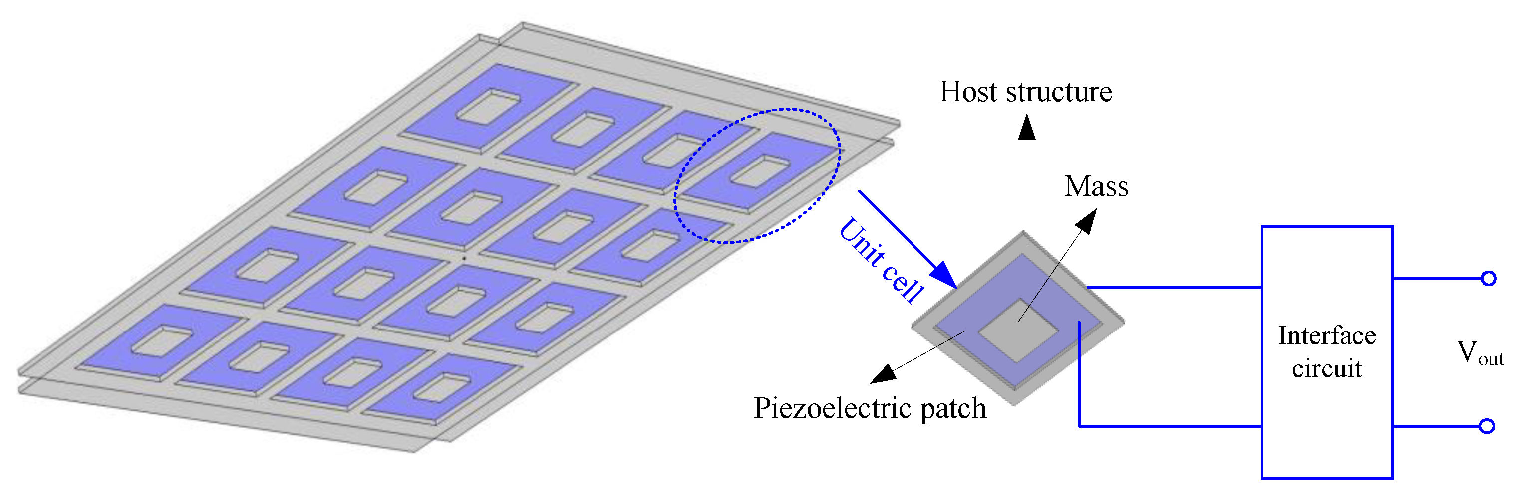
A schematic diagram of a PMPIC is shown in Figure 1. A thin rectangular plate is used as the thin plate, which can be decomposed into periodic unit cells. In each unit cell, a hole is cut off and then filled by a piezoelectric patch that supports one or multiple small square masses. The piezoelectric patch and the masses form a local resonator. The top and bottom electrodes of the piezoelectric patch are connected to an interface circuit for electric power conversion. Under excitations, transverse vibrations of the PMP will propagate along the plane of the thin plate. Due to the existence of local resonators, vibrations within specific frequency bands cannot propagate through the periodic cells, leading to locally resonant bandgaps. In this case, vibration energies will be localized in some unit cells, which then can be converted into electricity through the piezoelectric patch.
According to the bandgap theory, the band structure characteristics of the PMPIC are strongly dependent on the topology of the unit cell. Key components of each unit cell include the thin plate, the piezoelectric patch, the masses, and the interface circuit. Thus we need to optimize the topology of the unit cell to meet the band requirements of the PMPIC in practice, including material type, size, and shape, etc.
2.2. Binary Topology Optimization of the PMPIC
In this paper, the goal is to maximize the bandgap width so that more vibration energy can be harvested by the PMPIC. Generally speaking, a topology optimization problem always consists of distributing two material phases in a fixed design domain, and then an objective function is minimized or maximized under a number of constraints. The design domain is discretized into many small elements and material properties are assumed to be constant within each element. The design variable is the material density, which is equal to 0 or 1. If the design variable takes a zero value, we should have the first phase material in the element. Otherwise, we should have the second phase material in the element. In this problem, the physical size, shape, and connectivity of the unit cell are unknown in advance.
For structural topology optimization, a common method is called the solid isotropic material with penalization (SIMP) approach [31]. Material properties are modeled as the relative material density. In this case, design variables are the element relative densities. However, the drawback of this approach is that no physical material exists with properties described by power–law interpolation. In order to overcome this limitation, the levelset method has been recently introduced in the field of topology optimization [32]. Level set-based topology optimization methods can directly provide clear boundaries in optimal configurations that avoid the presence of intermediate densities. The level set method has been successfully used for topology optimization of metamaterials for the sake of controlling elastic wave propagation. However, the level set method is not feasible for optimizing the PMPIC due to the following two reasons: (i) the optimization function is difficult to be defined by including the interface circuit and the piezoelectric effect and (ii) the optimal result of the level set method may cause the piezoelectric patch to many independent pieces. In this case, the result may be inaccurate due to the piezoelectric effect, and PVEH is also inconvenient to carry out.
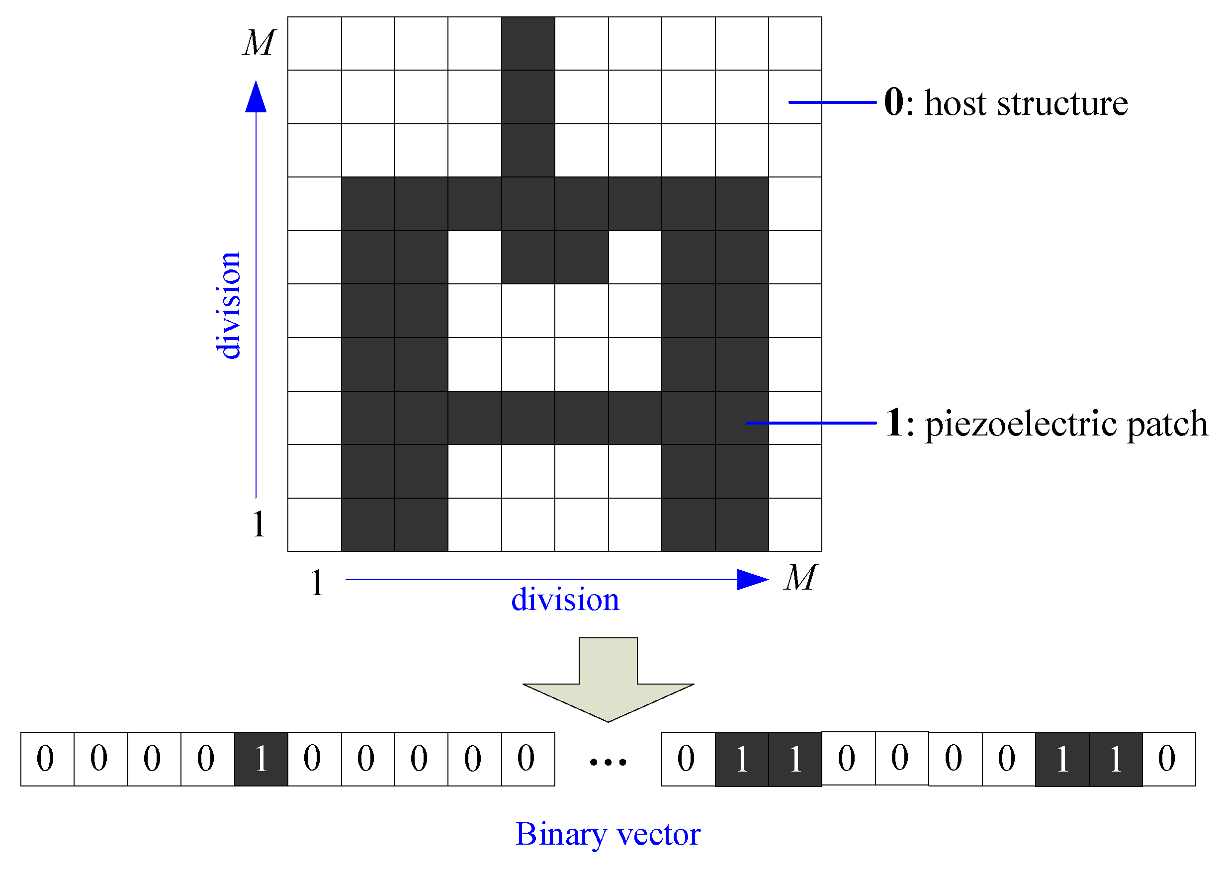
In this paper, a binary-like topology optimization scheme is proposed for the PMPIC, which is inspired by the idea of the SIMP approach. As shown in Figure 2, a square PMPIC unit cell is considered, where the interface circuit is not plotted. Then, the unit cell is divided into small elements and each element is marked by 0 or 1. If an element takes a zero value, we should choose thin plate material in the element. Otherwise, we should choose piezoelectric material in the element. In this way, the PMPIC unit cell can be represented by a 0–1 matrix. Then, the optimization problem is formulated to find the optimal topology of the 0–1 matrix for maximizing the bandgap width. The advantages of the above scheme include (i) compared with the SIMP approach, the above binary-like topology optimization method will not generate nonexistent materials with intermediate densities; (ii) compared with the level set approach, the above binary-like topology optimization method can easily control the connectivity of all “1” digits so that the piezoelectric patch forms a whole; (iii) the above binary-like topology optimization problem can be efficiently solved by common 0–1 programming algorithms or evolutionary optimization algorithms. In particular, it should be noted that each isolated host structure in the optimal result will be used as one mass, as shown in Figure 1, instead of mounting additional masses. That is to say, multiple masses may exist in the unit cell.
3. Bandgap Algorithm of the PMPIC by Extended Plane Wave Expansion Method
In recent years, piezoelectric phononic crystals with shunting circuits were studied to adjust and control bandgap characteristics for vibration suppression [33]. Lian et al. proposed to solve piezoelectric phononic crystal connected with resonant shunting circuits using an enhanced PWE method [34]. Inspired by the idea, the authors extended the PWE method to model and solve the PMPIC in this section.
3.1. Transverse Motion Equation of the PMPIC
Based on the Kirchhoff plate theory [35], transverse shear strains of a thin plate can be neglected. Then, its middle layer of the thin plate is looked at as the middle surface. In this case, the relationship between the strains (, , ) and transverse displacement () can be represented as Equation (1).
According to Newton’s method, the transverse vibration equation of a thin plate is given by
where is the bending moment, , are the density and the thickness of the thin plate, respectively, and , , are the stresses.
(i) For the host elastic plate: As a transversely isotropic elastic material, the relationship between the strains and the stresses is as follows [36]:
Then, its dynamic equation of transverse motion can be expressed as Equation (4) based on Equations (1)–(3).
where , , , , , , , are the density, Young’s modulus, the Poisson’s ratio, and the thickness of the thin plate, respectively [35].
(ii) For the piezoelectric patch: Furthermore, a piezoelectric patch can be assumed to be a transversely isotropic material. Then, the piezoelectric patch is also looked at as a thin plate, and its constitutive equation can be reduced to a 2D form as Equation (5).
where are elastic compliance parameters at the constant electric field, is the piezoelectric constant in the 3-1direction, is the dielectric permittivity atconstant stress, and , are the electric displacement and field along the z-axis, respectively. Moreover, Equation (5) can be rewritten as follows:
where, , , , , .
The piezoelectric patch is assumed to be polarized along the direction of z-axis, and then the electric field in the z-axis can be approximated as Equation (7) [10],
where is the output voltage across the two electrodes on the piezoelectric patch, and is the thickness of the piezoelectric patch.
Based on Equation (6), the bending moments can be calculated as follows:
where, , , .
By combining Equations (2), (7), and (8), we can obtain the transverse motion equation of the piezoelectric patch as
Referring to the idea in Ref. [34], an infinitesimal number multiplying the voltage is introduced into Equation (4) in order to unify the forms of Equations (4) and (9). Then, the unified motion equation can be written as
where the subscript (*) can be “s” for the thin plate or “p” for the piezoelectric patch, and .
(iii) For the interface circuit: This electric current flowing to the interface circuit can be calculated as Equation (11) using the long-wave approximation assumption [37].
where is the Laplace operator, and is the surface area of the electrode or the piezoelectric patch. On the other hand, the electric current can be written as
where denotes the impedance of the interface circuit.
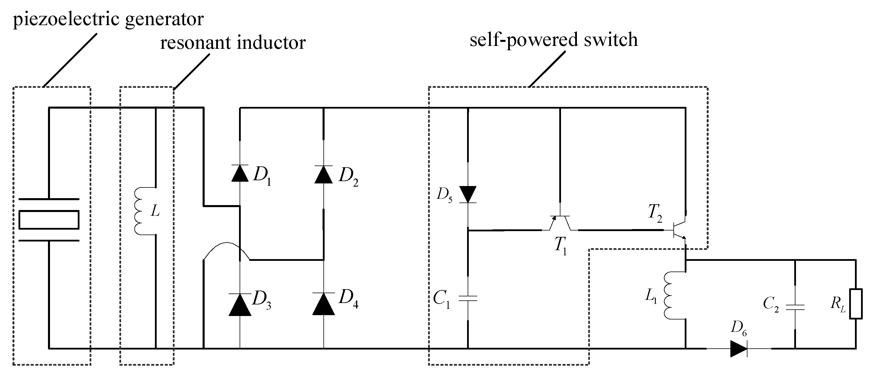
According to previous studies [20,38], a synchronized charge extraction circuit (SCEC) with a resonant inductor is chosen as the interface circuit, which is shown in Figure 3. In most times, the switch is off, and the capacitor is much less than the clamped capacitor of the piezoelectric patch; hence, we can only consider the resonant inductor as the electric load. In this case, the complex impedance of the interface circuit is .
By combing Equations (11) and (12), the following formulation can be obtained in the complex-frequency domain.
Furthermore, Equation (13) can be rewritten as
where , , , .
3.2. Bandgap Structures of the PMPIC by an Extended Plane Wave Expansion Method
For the complex 2D wave motion equation as Equation (10), it is difficult to obtainits analytical solution. Several numerical methods have been proposed to investigate 2D phononic crystals, such as the finite difference time domain method, finite element method, and PWE method. Due to its convenience, the PWE method is one of the most widely used methods to calculate bandgap structures of a 2D phononic crystal. As for piezoelectric coupling effects, an extended PWE method is presented here.
Due to a periodic structure, material properties (, , , and ) of the PMPIC are periodic functions of the spatial coordinates (). In Figure 2, it is assumed that denotes the set of small elements filled with piezoelectric patch and the center element belongs to . Then, material properties of the center element can be represented as Equation (15) according to its Fourier series expansion
where is the Fourier coefficient, can be any of , , , or , is the reciprocal lattice vector and are the x-axis and y-axis lattice vectors in the reciprocal space, respectively, and is the primitive space vector. Here, , and is the lattice constant of the unit cell. Furthermore, can be defined as
where is the area of the unit cell. Furthermore, the integration of Equation (16) can be calculated as
where and denote material properties (, , , or ) of the piezoelectric patch and host structure, respectively. is the filling ratio of each small element in the unit cell. is called a structural function, which is defined as
where is the area of the small element. In this paper, the piezoelectric patch in any small element is square, so we will have
where and are x and y components of the reciprocal vector , and sinc(●) is the cardinal sine function.
According to the basic properties of Fourier transform, any other small element belonging to will have . Then, Fourier transform of material constants of the piezoelectric patch in the unit cell can be expressed as
where , denotes the center position of the ith small element and . When the ith small element belongs to , , otherwise . Thus can be looked at as a distribution function of piezoelectric material in the unit cell, which is just the optimization target of this paper.
Based on the Bloch theorem, the displacement and output voltage in Equation (10) can be defined as
where is the Bloch wave vector which is restricted to the first irreducible Brillouin zone. is also a periodic function with the same period as that of material properties, so it can be expanded as
Based on Equations (21) and (22), we will have
Substituting Equations (15) and (23) into Equation (10), we will have
Similarly, Equation (14) can also be derived as Equation (25).
Finally, Equations (24) and (25) can be rearranged as the following standard eigenvalue equation.
where , , , , , , , denote the reciprocal lattice vectors.
Based on Equation (26), we can obtain the corresponding value of once the wave vector is specified. Generally speaking, the wave vector is always chosen along the edges of the irreducible part of the first Brillouin zone. In this case, the dispersion curves will be obtained, and then vibration bandgaps can be calculated.
4. Binary-Like Topology Optimization of the Unit Cell by Extended Genetic Algorithm
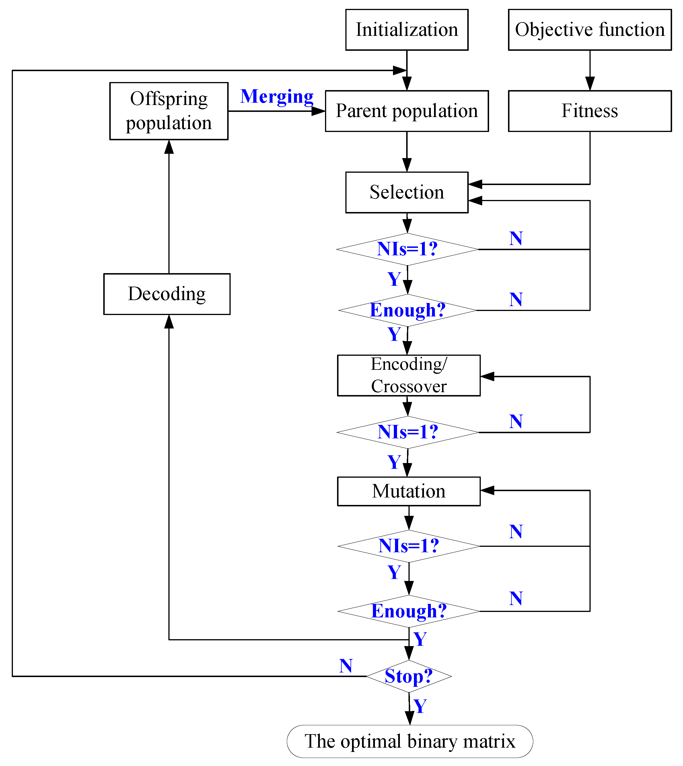
As shown in Figure 2, the distribution of the piezoelectric patch can be represented as a binary matrix. Thus, topology optimization of the unit cell is equivalent to find the optimal matrix to maximize the bandgaps. Moreover, the binary matrix can be further rewritten as a -dimension vector, which can be looked at as encoding the matrix. In this case, the problem of the mentioned binary-like topology optimization will be solved by the genetic algorithm.
According to the previous work [20], the PVEH performance can be improved greatly once the resonant frequency is equal to the excitation frequency. For engineering applications, the central frequency of target structural vibration is assumed to be , and then we can choose the inductor as follows:
It is obvious that depends on . Furthermore, is related to the distribution of the piezoelectric patch. Thus, it is valuable that both the piezoelectric patch and the interface circuit can be topologically optimized simultaneously to realize high-efficiency and broadband PVEH in structures. The detailed procedure is described as follows.
(1) Definition of the objective function and the fitness: In order to achieve broadband and low-frequency vibration energy harvesting, we hope to maximize the width of the first-order bandgap. Thus, the optimization objective function can be defined as
where denote the first-order and second-order dispersion curves calculated by Equation (26), and is the binary matrix representing the topology distribution of the piezoelectric patch. Then, the optimization variables are the elements of , which are defined as
Different from previous studies on vibration isolations, all elements of “1” digits in should be connected as a whole in order to ensure an integrated piezoelectric patch in this paper. Otherwise, Equation (9) does not hold again. By coincidence, this task can be easily overcome by the algorithm of finding the number of islands (NIs) in the {0, 1} matrix (). At the same time, the fitness of each is defined as the width of the first-order bandgap ().
(2) Initialization: Initialization parameters include geometric and material properties of the thin plate and the piezoelectric patch, the population size, the iterative times, the selection rate, the crossover probability, the mutation probability, and . Here, it should be noted that each individual in the population must be selected to make its NIs be equal to 1.
(3) Selection: For each individual in the population, the first-order and second-order dispersion curves are simulated by Equation (26), and then the first-order band gap is calculated to define its fitness. If the first-order bandgap does not exist, a small number is assigned as its fitness to keep this individual. Based on the roulette wheel selection algorithm, the number (e.g., the population size × the selection rate) of individuals in the initialization parent population is selected to construct a new mating pool.
(4) Encoding and crossover: Firstly, we choose randomly two individuals in the mating pool as the parents and transform them into a -dimension vector. Then, the selected two individuals are mated to create two offspring for replacing their parents according to a crossover probability (). Similarly, each offspring will be checked whether its NIs areequal to 1 or not. If not, the crossover operation needs to be carried out again. Inthis way, an offspring population will be created.
(5) Mutation and decoding: Each individual in the offspring population is mutated according to the mutation probability . The mutation position is chosen randomly, where the element value switches to its opposite. Additionally, the mutated individual will be checked whether its NIs are equal to 1 or not. If not, the mutation operation needs to be carried out again. In this way, a mutated offspring population will be created. Next, each individual in the mutated offspring population is rearranged as a binary matrix. The resulted offspring population will be merged with the parent population to create the new parent population.
(6) Termination: Repeating steps (3) to (5) until the iterative times are reached. Then, we can obtain the optimal first-order bandgap width and the corresponding optimal binary matrix. Based on the binary matrix, the optimal topology of the unit cell is realized.
In summary, the binary-like topology optimization flowchart using the extended GA algorithm is plotted in Figure 4.
5. Simulations and Discussions
In order to validate the proposed method, numerical simulations are carried out to carry out the binary-like topology optimization procedure using the extended GA algorithm. Geometrical and material parameters in simulations are listed in Table 1 and Table 2, respectively.
5.1. Feasibility of the Proposed Algorithm
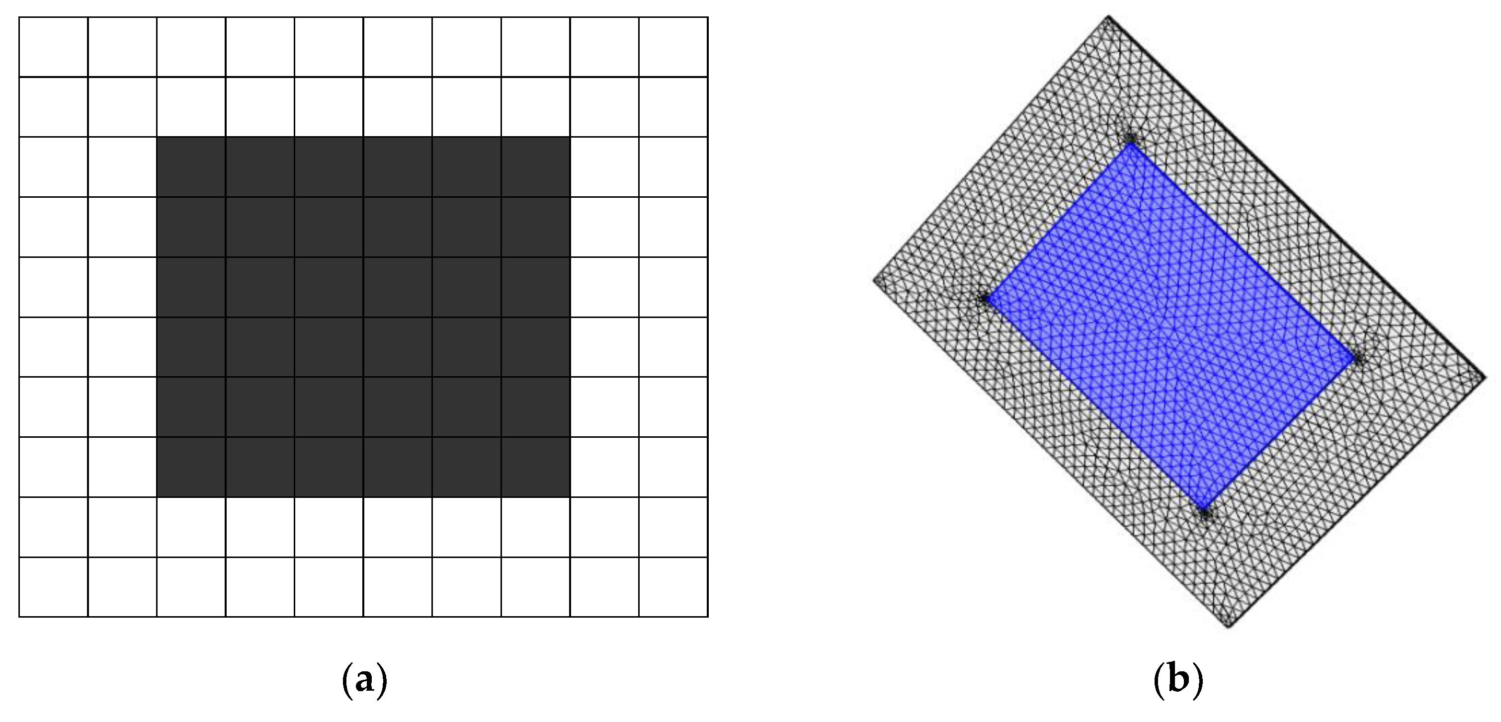
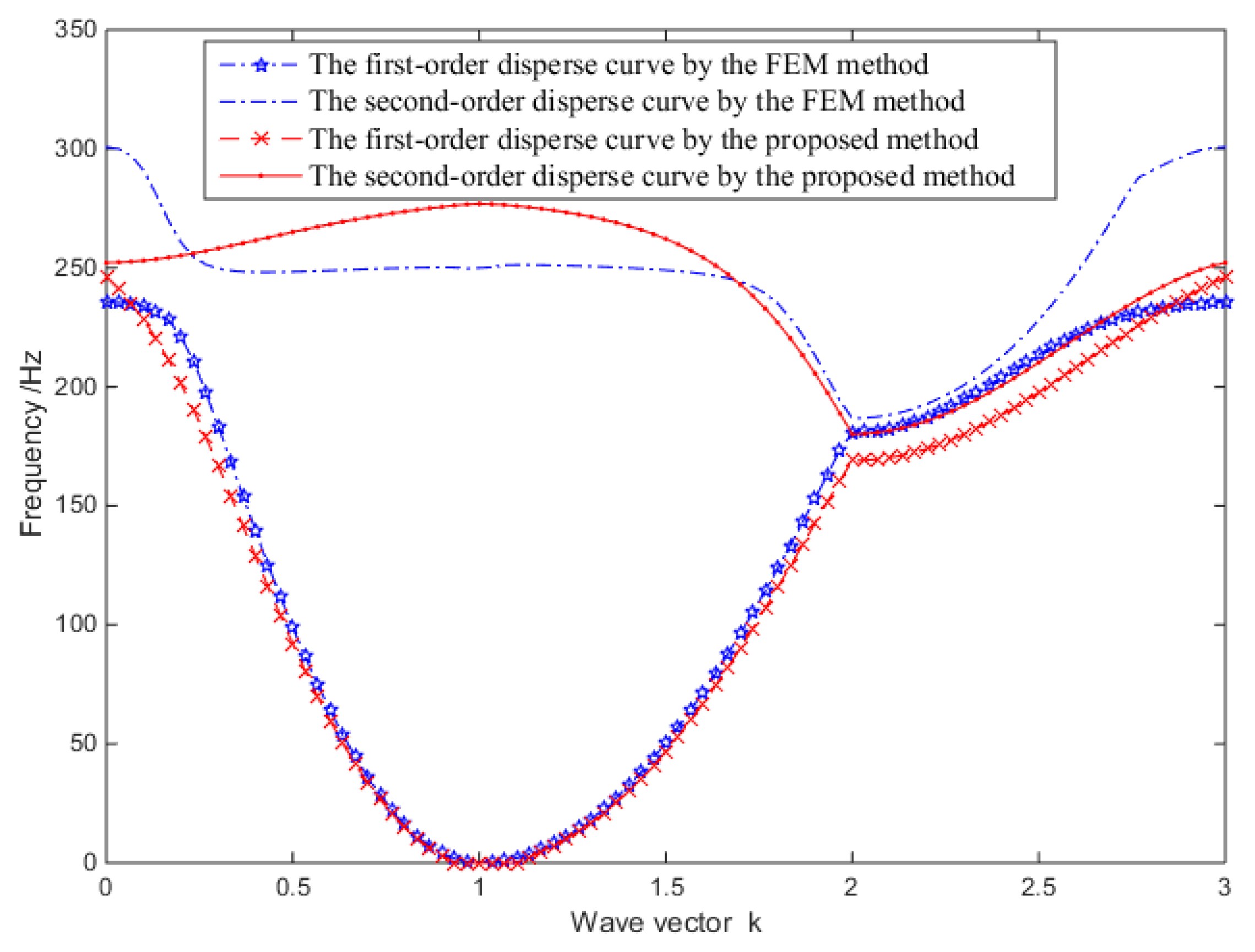
The unit cell with configuration A, as shown in Figure 5a, is considered for the first numerical example and M is randomly selected as 10. Then, it is divided into 10 × 10 small elements. For this configuration, its finite element model (FEM) is built by the Comsol software and here the inductor is chosen as H. Then, the first and second dispersion curves are calculated by the proposed algorithm and the FEM simulation, respectively. The results are shown in Figure 6, and we can see that (i) numerical results are close to those of FEM simulations; hence, the proposed bandgap algorithm is testified to be effective; (ii) there is no full bandgaps under configuration A, while local bandgaps exist along the directions of and ; (iii) the bias between the numerical and FEM results may mainly come from the approximation error of the long-wave hypothesis in Equation (11).
5.2. Effects of the Interface Circuit (L)
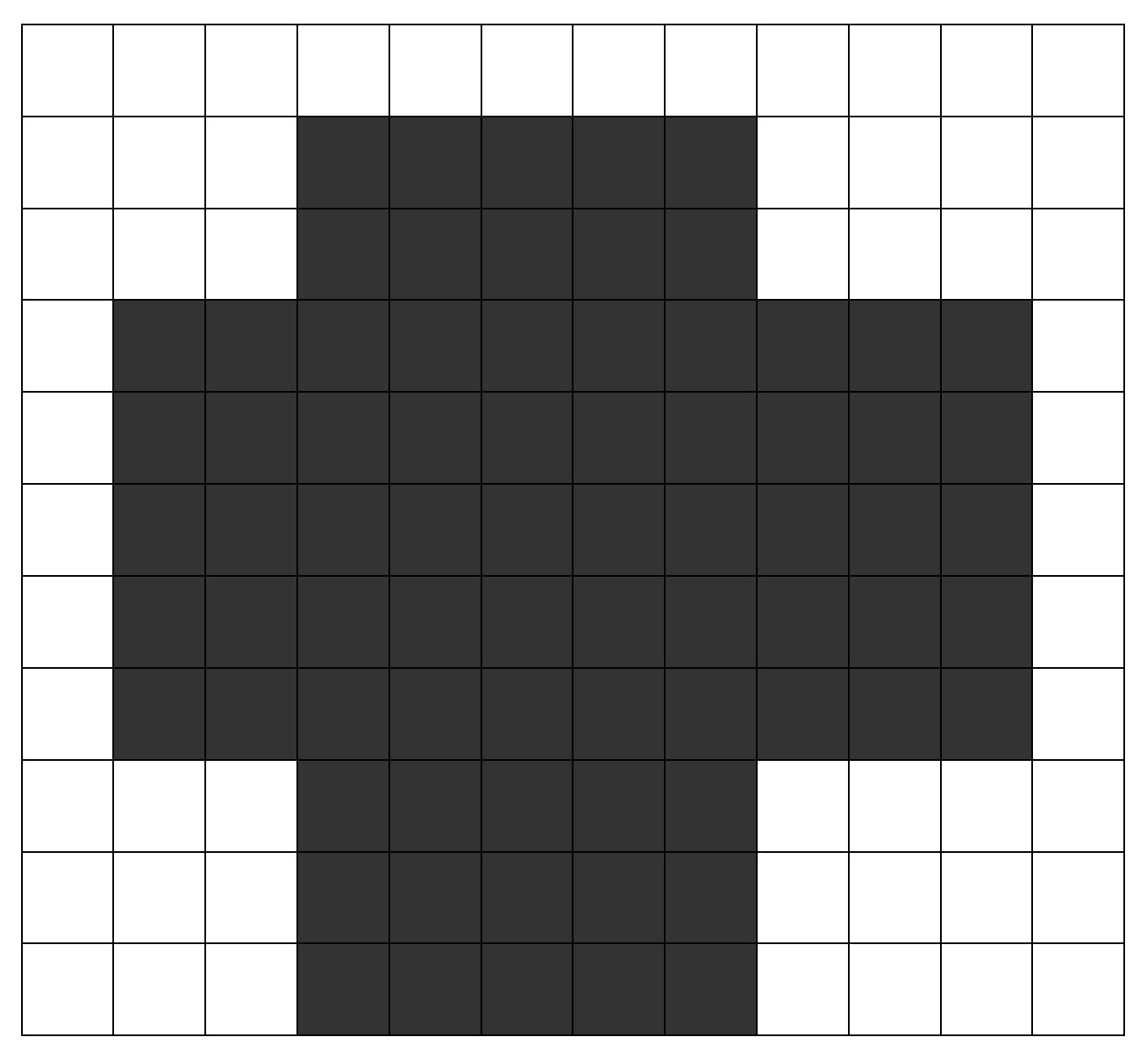
Furthermore, the unit cell with configuration B as Figure 7 is considered for the second numerical example, and M is randomly selected as 12. Then, it is divided into 12 × 12 small elements.
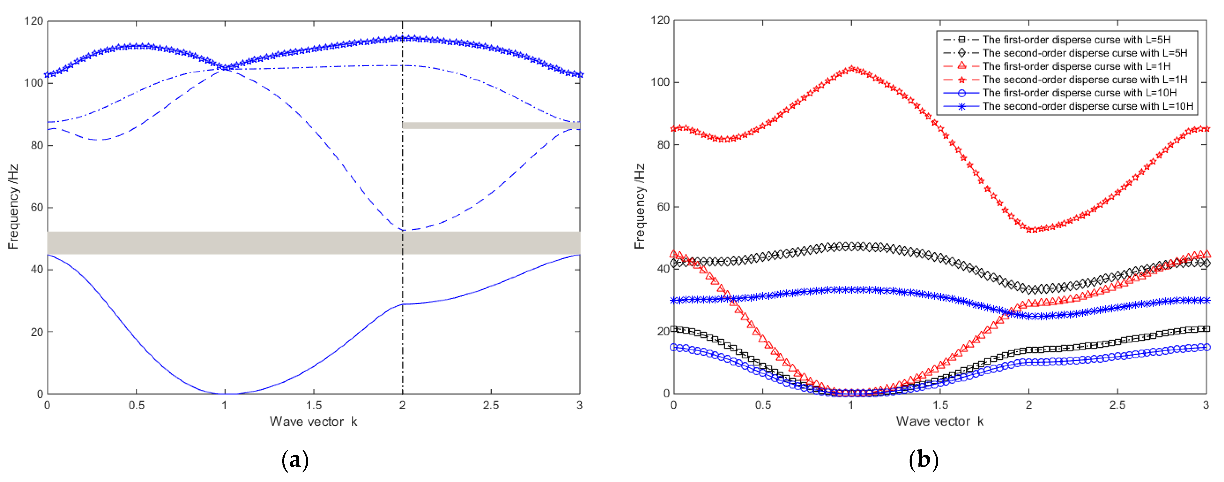
Firstly, the inductor is chosen as H, and the first four disperse curves are calculated as Figure 8a. It can be seen that (i) besides local bandgaps, there is a full bandgap, which is called the first bandgap. The bandgap width is equal to 7.99; (ii) compared with configuration A, it may be easier to generate full bandgaps by using a nonrectangular configuration of piezoelectric material. Indeed, it provides the basis of topology optimization in this paper.
Then, in order to investigate the effects of the interface circuit, different values of the inductor () are chosen. The first-order bandgaps are calculated and shown in Figure 8b, respectively. It can be seen that (i)the first bandgap will shift to the low-frequency region with the increase of ; therefore, large will benefit low-frequency vibration energy harvesting; (ii) with the increase of , the width of the first bandgap firstly increases and then decreases. It means that there may be an optimal to obtain the maximum width of the first bandgap, which also will indicate the feasibility of topology optimization.
5.3. Topology Optimization of the PMPIC
In order to validate the topology optimization algorithm, the procedure shown in Figure 4 is carried out by MATLAB Software. Firstly, the inductor is fixed as H, and the unit cell is divided into 10 × 10 small elements (e.g., ). Parameters of the GA are set as the population size, the selection rate, the crossover probability, and the mutation probability, which are equal to 50, 0.5, 0.7, and 0.001, respectively.
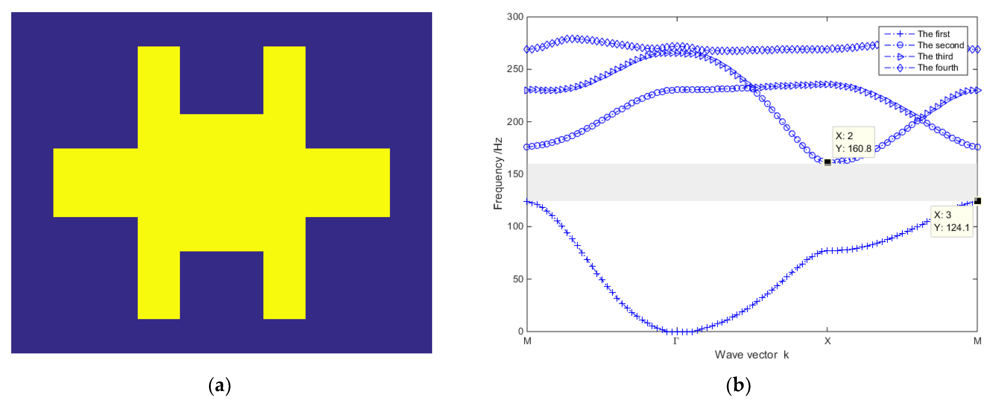
In order to show the structural topology clearly, two colors are applied for different materials. The Blue area denotes the host base structure, and the yellow area denotes the piezoelectric patch. The optimal topology configuration of the unit cell is shown in Figure 9a. Moreover, the first four dispersion curves are plotted in Figure 9b, and the maximum bandgap width is equal to 36.6891 Hz ([124.1, 160.8] Hz). Obviously, the maximum bandgap width is much larger than that of configuration B, and the structural topology of the piezoelectric patch is nonrectangular.
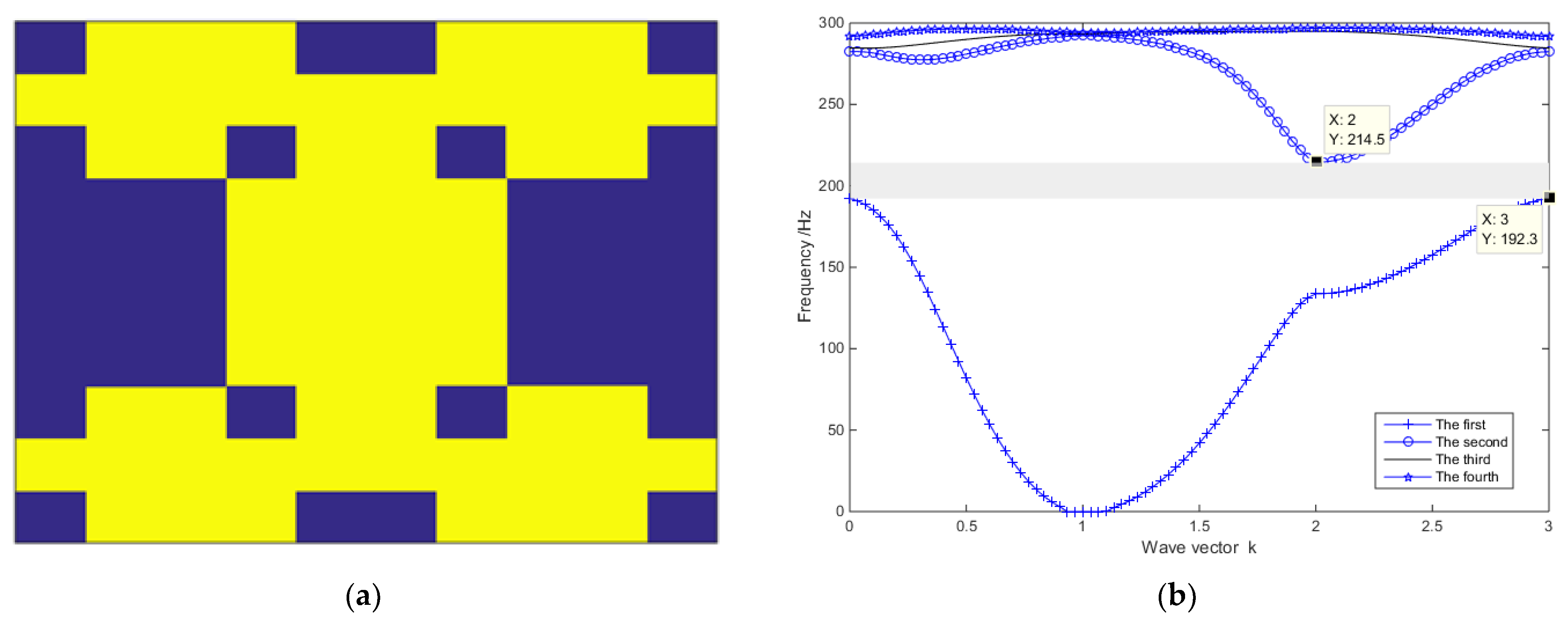
Secondly, it is desired to optimize the structural topology and the interface circuit simultaneously. Here, the central frequency is assumed to be 200 Hz, and the unit cell is also divided into 10 × 10 small elements (e.g., ). The optimal topology configuration of the unit cell is shown in Figure 10a, the first four dispersion curves are plotted in Figure 10b, and the maximum bandgap width is equal to 22.4 Hz ([192.3, 214.7]Hz). At the same time, the inductor is calculated as . Obviously, is close to the center of the optimal bandgap. Four isolated host structures in the optimal result can be used for local masses.
In the end, it should be emphasized that M is a key parameter and the precision of material distribution increases with M. However, large M will cause the amount of optimization calculation to increase rapidly. Without loss of feasibility, this paper pays less attention on calculation efficiency. As for this problem, it may be overcome by using advanced calculation tools such as supercomputing platforms or fast optimization algorithms.
6. Conclusions
In this paper, a self-powered SCEC is used as the interface circuit connected to the PMP for harvesting structural vibration energy. In order to optimize the topology structure of the PMPIC, a binary-like topology optimization process is first presented. Then, simulations are conducted to validate the proposed method. The main highlights of this paper may include the following: (i) A binary-like topology optimization approach is first proposed for the PMPIC by dividing the unit cell into a {0, 1} matrix indicating material distribution so that the coupled structure and circuit can be optimized simultaneously; (ii) an elastic–electro–mechanical coupling model is built for the coupled PMP and self-powered SCEC with a resonant inductor; (iii) an extended plane wave expansion method is presented to model the bandgap character of the PMPIC, which is numerically solved by the Bloch theorem; (iv) GA is extended to perform topology optimization of the PMPIC by adding the restriction of NIs. In the future, a better approximation of Equation (11) can be studied to replace the long-wave hypothesis in order to increase its accuracy, and fast optimization algorithms need to be explored to reduce the computation cost. In addition, more experimental tests need to be performed to make sure theoretic results. For real-world experiment design, some uncertainties should be addressed and explored in the future, such as fabrication error, nonuniformity of piezoelectrical material, model approximation error, the time delay of the self-powered switch, etc.
Author Contributions
Conceptualization, Z.C. and Y.X.; methodology, Z.C.; validation, Z.C. and Y.W.; formal analysis, Z.C.; writing—original draft preparation, Z.C.; writing—review and editing, Y.X.; project administration, Z.C.; funding acquisition, Z.C. and Y.X. All authors have read and agreed to the published version of the manuscript.
Funding
This study was supported by the National Natural Science Foundation of China, GrantNumber 51911530202 and 51577189, and the Royal Society under the International Exchanges Scheme-Cost Share Programme, Grant Number IEC\NSFC\181462.
Institutional Review Board Statement
Not applicable.
Informed Consent Statement
Not applicable.
Data Availability Statement
Not applicable.
Acknowledgments
We thank all the participants in this study.
Conflicts of Interest
The authors declare no conflict of interest.
References
- Li, J.; Zahra, S.K.; Aliabadi, M.H. Boundary element modelling of ultrasonic Lamb waves for structural health monitoring. Smart Mater. Struct. 2020, 29, 105030. [Google Scholar] [CrossRef]
- Cantero-Chinchilla, S.; Beck, J.L.; Chiachio, M.; Chiachio, J.; Chronopoulos, D.; Jones, A. Optimal sensor and actuator placement for structural health monitoring via an efficient convex cost-benefit optimization. Mech. Syst. Signal Pract. 2020, 144, 106901. [Google Scholar] [CrossRef]
- Liu, C.Y.; Teng, J.; Wu, N. A wireless strain sensor network for structural health monitoring. Shock Vib. 2015, 2015, 740471. [Google Scholar] [CrossRef]
- Faisal, K.S.; Zeadally, Z.S. Energy harvesting in wireless sensor networks: A comprehensive review. Renew. Sust. Energ. Rev. 2016, 55, 1041–1054. [Google Scholar]
- Sah, D.K.; Amgoth, T. Renewable energy harvesting schemes in wireless sensor networks: A survey. Inf. Fusion 2020, 63, 223–247. [Google Scholar] [CrossRef]
- Peruzzi, G.; Pozzebon, A. A review of energy harvesting techniques for low power wide area networks (LPWANs). Energies 2020, 13, 3433. [Google Scholar] [CrossRef]
- Anton, S.R.; Sodano, H.A. A review of power harvesting using piezoelectric materials (2003–2006). Smart Mater. Struct. 2007, 16, R1–R21. [Google Scholar] [CrossRef]
- Wang, J.L.; Geng, L.F.; Ding, L.; Zhu, H.J.; Yurchenko, D. The state-of-the-art review on energy harvesting from flow-induced vibrations. Appl. Energ. 2020, 267, 114902. [Google Scholar] [CrossRef]
- Lee, S.; Youn, B.D. A design and experimental verification methodology for an energy harvester skin structure. Smart Mater. Struct. 2011, 20, 057001. [Google Scholar] [CrossRef]
- Yoon, H.; Youn, B.D.; Kim, H.S. Kirchhoff plate theory-based electromechanically-coupled analytical model considering inertia and stiffness effects of a surface-bonded piezoelectric patch. Smart Mater. Struct. 2016, 25, 025017. [Google Scholar] [CrossRef]
- Aridogan, U.; Basdogan, I.; Erturk, A. Analytical modeling and experimental validation of a structurally integrated piezoelectric energy harvester on a thin plate. Smart Mater. Struct. 2014, 23, 045039. [Google Scholar] [CrossRef]
- Zeng, M.; Liu, J.; Zhou, L.; Mendes, R.G.; Dong, Y.; Zhang, M.Y.; Cui, Z.H.; Cai, Z.; Zhang, Z.; Zhu, D.; et al. Bandgap tuning of two-dimensional materials by sphere diameter engineering. Nat. Mater. 2020, 19, 528–533. [Google Scholar] [CrossRef]
- Chen, Z.S.; Yang, Y.M.; Lu, Z.M.; Luo, Y.T. Broadband characteristics of vibration energy harvesting using one-dimensional phononic piezoelectric cantilever beams. Physica B 2013, 410, 5–12. [Google Scholar] [CrossRef]
- Wu, L.Y.; Chen, L.W.; Liu, C.M. Acoustic energy harvesting using resonant cavity of a sonic crystal. Appl. Phys. Lett. 2009, 95, 013506. [Google Scholar] [CrossRef]
- Liu, Z.Y.; Zhang, X.X.; Mao, Y.W.; Zhu, Y.Y.; Yang, Z.Y.; Chan, C.T.; Sheng, P. Locally resonant sonic materials. Science 2000, 289, 1734–1736. [Google Scholar] [CrossRef]
- Sugino, C.; Leadenham, S.; Ruzzene, M.; Erturk, A. An investigation of electroelastic bandgap formation in locally resonant piezoelectric metastructures. Smart Mater. Struct. 2017, 26, 055029. [Google Scholar] [CrossRef] [Green Version]
- Wang, J.L.; Sun, S.K.; Tang, L.H.; Hu, G.B.; Liang, J.R. On the use of metasurface for vortex-induced vibration suppression or energy harvesting. Energy Convers. Manag. 2021, 235, 113991. [Google Scholar] [CrossRef]
- Kherraz, N.; Haumesser, L.; Levassort, F.; Benard, P.; Morvan, B. Controlling Bragg gaps induced by electric boundary conditions in phononic piezoelectric plates. Appl. Phys. Lett. 2016, 108, 093503. [Google Scholar] [CrossRef]
- Chen, Z.S.; He, J.; Wang, G. Vibration bandgaps of piezoelectric metamaterial plate with local resonators for vibration energy harvesting. Shock Vib. 2019, 2019, 1397123. [Google Scholar] [CrossRef]
- Chen, Z.S.; Xia, Y.M.; He, J.; Xiong, Y.P.; Wang, G. Elastic-electro-mechanical modeling and analysis of piezoelectric metamaterial plate with a self-powered synchronized charge extraction circuit for vibration energy harvesting. Mech. Syst. Signal Pract. 2020, 143, 106824. [Google Scholar] [CrossRef]
- Zhang, X.D.; Zhang, H.L.; Chen, Z.S.; Wang, G. Simultaneous realization of large sound insulation and efficient energy harvesting with acoustic metamaterial. Smart Mater. Struct. 2018, 27, 105018. [Google Scholar] [CrossRef]
- Steven, J.C.; David, C.D. Band structure optimization of two-dimensional photonic crystals in H-polarization. J. Comput. Phys. 2000, 158, 214–224. [Google Scholar]
- Sigmund, O.; Jensen, J.S. Topology optimization of phononic band gap materials and structures. In Proceedings of the 5th World Congress on Computational Mechanics, Vienna, Austria, 5–12 July 2002. [Google Scholar]
- George, A.G.; Daniel, S.W.; Raymond, W.; Anuraag, M. Genetic algorithm optimization of phononic bandgap structures. Int. J. Solids Struct. 2006, 43, 5851–5866. [Google Scholar]
- Zhong, H.L.; Wu, F.G.; Yao, L.N. Application of genetic algorithm in optimization of band gap of two-dimensional phononic crystals. Acta Phy. Sin. 2006, 55, 275–280. [Google Scholar] [CrossRef]
- Xie, L.X.; Xia, B.Z.; Liu, J.; Huang, G.L.; Lei, J.R. An improved fast plane wave expansion method for topology optimization of phononic crystals. Int. J. Mech. Sci. 2017, 120, 171–181. [Google Scholar] [CrossRef]
- Xie, Y.M.; Steven, G.P. A simple evolutionary procedure for structural optimization. Comput. Struct. 1993, 49, 885–896. [Google Scholar] [CrossRef]
- Sivapuram, R.; Picelli, R. Topology optimization of binary structures using integer linear programming. Finite Elem. Anal. Des. 2018, 139, 49–61. [Google Scholar] [CrossRef]
- Picelli, R.; Ranjbarzadeh, S.; Sivapuram, R.; Gioria, R.S.; Silva, E.C.N. Topology optimization of binary structures under design-dependent fluid-structure interaction loads. Struct. Multidiscip. Optim. 2020, 62, 2101–2116. [Google Scholar] [CrossRef]
- Sivapuram, R.; Picelli, R. Topology design of binary structures subjected to design-dependent thermal expansion and fluid pressure loads. Struct. Multidiscip. Optim. 2020, 61, 1877–1895. [Google Scholar] [CrossRef]
- Krishna, L.S.R.; Mahesh, N.; Sateesh, N. Topology optimization using solid isotropic material with penalization technique for additive manufacturing. Mater. Today Proc. 2017, 4, 1414–1422. [Google Scholar] [CrossRef]
- Wu, J.L.; Luo, Z.; Li, H.; Zhang, N. Level-set topology optimization for mechanical metamaterials under hybrid uncertainties. Comput. Methods Appl. Mech. Eng. 2017, 319, 414–441. [Google Scholar] [CrossRef]
- Billon, K.; Montcoudiol, N.; Aubry, A.; Pascual, R.; Mosca, F.; Jean, F.; Pezerat, C.; Bricaul, C.; Chesne, S. Vibration isolation and damping using a piezoelectric flextensional suspension with a negative capacitance shunt. Mech. Syst. Signal Pract. 2020, 140, 106696. [Google Scholar] [CrossRef]
- Lian, Z.Y.; Jiang, S.; Hu, H.P.; Dai, L.X.; Chen, X.D.; Jiang, W. An enhanced plane wave expansion method to solve piezoelectric phononic crystal with resonant shunting circuits. Shock Vib. 2016, 2016, 4015363. [Google Scholar] [CrossRef] [Green Version]
- Rao, S.S. Vibration of Continuous Systems; Wiley: New York, NY, USA, 2007; pp. 73–77. [Google Scholar]
- Erturk, A.; Inman, D.J. Piezoelectric Energy Harvesting; Wiley: New York, NY, USA, 2011; pp. 375–377. [Google Scholar]
- Thorp, O.; Ruzzene, M.; Baz, A. Attenuation and localization of wave propagation in rods with periodic shunted piezoelectric patches. Smart Mater. Struct. 2001, 10, 979–989. [Google Scholar] [CrossRef]
- Chen, Z.S.; He, J.; Liu, J.H.; Xiong, Y.P. Switching delay in self-powered nonlinear piezoelectric vibration energy harvesting circuit: Mechanisms, effects, and solutions. IEEE Trans. Power Electron. 2019, 34, 2427–2440. [Google Scholar] [CrossRef]
Figure 1.
Schematic diagram of a PMPIC.

Figure 2.
Binary representative of the PMPIC unit cell.

Figure 3.
The structure of a self-powered SCEC with a resonant inductor.

Figure 4.
The binary-like topology optimization flowchart using the extended GA algorithm.

Figure 5.
The unit cell of configuration A: (a) configuration A and (b) its FEM.

Figure 6.
The dispersion curves under configuration A.

Figure 7.
The unit cell of configuration B.

Figure 8.
The dispersion curves under configuration B: (a) the first four disperse curves and (b) comparison of the first bandgap.
Figure 8.
The dispersion curves under configuration B: (a) the first four disperse curves and (b) comparison of the first bandgap.

Figure 9.
The optimal result under : (a) topology configuration of the unit cell and (b) the first four dispersion curves.
Figure 9.
The optimal result under : (a) topology configuration of the unit cell and (b) the first four dispersion curves.

Figure 10.
The optimal result under : (a) topology configuration of the unit cell and (b) the first four dispersion curves.
Figure 10.
The optimal result under : (a) topology configuration of the unit cell and (b) the first four dispersion curves.


Table 1.
Geometrical parameters of the unit cell.
| (mm) | (mm) | (mm) |
|---|---|---|
| 100 | 1 | 0.2 |
Table 2.
Material parameters of the unit cell.
| Parameters | PZT-5H | Al |
|---|---|---|
| Density (kg/m3) | 7500 | 2700 |
| Young’s modulus E (Pa) | 63 × 109 | 70 × 109 |
| Poisson’s ratio | 0.34 | 0.33 |
| Elastic compliance (m2/N) | 16.5 × 10⁻¹² | / |
| Elastic compliance (m2/N) | −4.78 × 10⁻¹² | / |
| Elastic compliance (m2/N) | 42.6 × 10⁻¹² | / |
| Piezoelectric constant (C/N) | −274 × 10−12 | / |
| Dielectric permittivity (F/m) | 30.1 × 10⁻⁹ | / |
Publisher’s Note: MDPI stays neutral with regard to jurisdictional claims in published maps and institutional affiliations. |
© 2021 by the authors. Licensee MDPI, Basel, Switzerland. This article is an open access article distributed under the terms and conditions of the Creative Commons Attribution (CC BY) license (https://creativecommons.org/licenses/by/4.0/).
Share and Cite
MDPI and ACS Style
Chen, Z.; Xiong, Y.; Wei, Y. Binary-Like Topology Optimization of Piezoelectric Metamaterial Plate with Interface Circuits Using Extended Plane Wave Expansion Method. Appl. Sci. 2021, 11, 5191. https://doi.org/10.3390/app11115191
AMA Style
Chen Z, Xiong Y, Wei Y. Binary-Like Topology Optimization of Piezoelectric Metamaterial Plate with Interface Circuits Using Extended Plane Wave Expansion Method. Applied Sciences. 2021; 11(11):5191. https://doi.org/10.3390/app11115191
Chicago/Turabian StyleChen, Zhongsheng, Yeping Xiong, and Yongxiang Wei. 2021. "Binary-Like Topology Optimization of Piezoelectric Metamaterial Plate with Interface Circuits Using Extended Plane Wave Expansion Method" Applied Sciences 11, no. 11: 5191. https://doi.org/10.3390/app11115191
Note that from the first issue of 2016, this journal uses article numbers instead of page numbers. See further details here.