Article

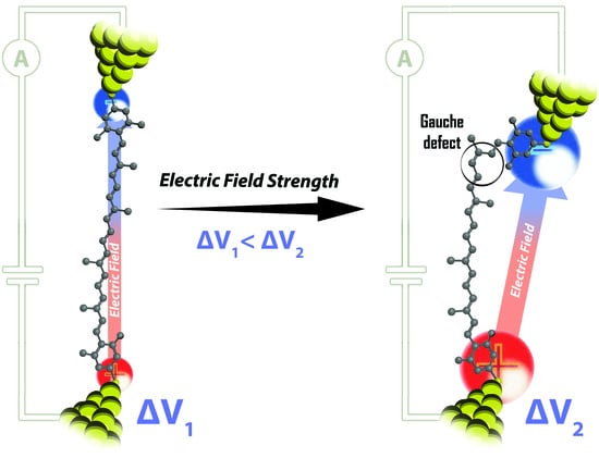
Tuning Single-Molecule Conductance by Controlled Electric Field-Induced trans-to-cis Isomerisation

1
Department of Chemistry, Federal University of São Carlos, São Carlos 13565-905, Brazil
2
Max Planck Institute for Polymer Research, Ackermannweg 10, 55128 Mainz, Germany
3
Departamento de Química de los Materiales, Facultad de Química y Biología, Universidad de Santiago de Chile, Casilla 40, Correo 33, Santiago 9170022, Chile
4
Department of Chemistry, Myongji University, Myongji-Ro 116, Cheoin-Gu, Yongin 17058, Gyeonggi-Do, Korea
5
Department of Chemistry, Faculty of Natural & Mathematical Sciences, King’s College London Britannia House, 7 Trinity Street, London SE1 1DB, UK
*
Authors to whom correspondence should be addressed.
Current address: Max Planck Institute for Polymer Research, Ackermannweg 10, 55128 Mainz, Germany.
Appl. Sci. 2021, 11(8), 3317; https://doi.org/10.3390/app11083317
Submission received: 13 March 2021 / Revised: 3 April 2021 / Accepted: 5 April 2021 / Published: 7 April 2021
(This article belongs to the Special Issue Molecular Electronics)

Abstract

:
External electric fields (EEFs) have proven to be very efficient in catalysing chemical reactions, even those inaccessible via wet-chemical synthesis. At the single-molecule level, oriented EEFs have been successfully used to promote in situ single-molecule reactions in the absence of chemical catalysts. Here, we elucidate the effect of an EEFs on the structure and conductance of a molecular junction. Employing scanning tunnelling microscopy break junction (STM-BJ) experiments, we form and electrically characterize single-molecule junctions of two tetramethyl carotene isomers. Two discrete conductance signatures show up more prominently at low and high applied voltages which are univocally ascribed to the trans and cis isomers of the carotenoid, respectively. The difference in conductance between both cis-/trans- isomers is in concordance with previous predictions considering π-quantum interference due to the presence of a single gauche defect in the trans isomer. Electronic structure calculations suggest that the electric field polarizes the molecule and mixes the excited states. The mixed states have a (spectroscopically) allowed transition and, therefore, can both promote the cis-isomerization of the molecule and participate in electron transport. Our work opens new routes for the in situ control of isomerisation reactions in single-molecule contacts.

Graphical Abstract

1. Introduction

The development of novel, more efficient ways to control molecular reactions has been a restless quest for synthetic chemists. Many different triggers, such as light, heat or external electric fields (EEF) are being used to promote chemical reactions [1,2]. EEF have been shown to be able to stabilize conventionally non-favourable electronic structures [3] and thus to enable new transition states [4,5] in a theoretically predictable manner. These field-induced chemical reactivity experiments, which are well reported in single-molecule devices [3,5], represent an exciting alternative to traditional bulk chemical catalyst approaches since EEF provide a cost-, material-efficient methodology to precisely control molecular reactions in a cleaner, more sustainable way.
In the molecular electronics (ME) field, one of the most appealing single-molecule reactions is the isomerisation reaction [6,7,8,9], because small changes in the molecular structure give rise to a significant change in the conductance of the molecular wire [8,9]. The molecular configuration constitutes a defining parameter for the intrinsic conducting properties of a molecule. Moreover, measuring single-molecule conductance can be used to follow structural changes in a molecular contact [10,11,12,13], opening the way to real time detection of electrical currents associated with in situ stimuli-induced molecular structural changes [5,14,15]. Charge transport across molecular systems as a function of molecule configuration has been widely studied theoretically [16,17,18] and experimentally [8,9,11,19,20,21,22], including cis-/trans- isomerization. Different isomers exhibit characteristic conductance values that can be attributed to various effects, such as the potential energy barrier variation due to structural change [8,17,19], the different contact geometry [8,9,16,21], or the different energies of the frontier molecular orbitals with respect to the electrode Fermi levels for each isomer [17,18,22]. Behind unravelling the particular phenomenology for each system, the detection of electrical currents across molecules in metal|molecule|metal junctions [13,23,24] have been essential to electrically characterize structural changes of individual molecular systems [25].
Here, we report on single-molecule scanning tunnelling microscopy break junction (STM-BJ) conductance experiments of all-E-carotene with terminal 1,5-dimethyl-3-methylthiophenyl groups (trans-TMC, Figure 1a) and 9-Z-carotene with terminal 3-methylthiophenyl groups (cis-TMC, Figure 1b) carotenoid derivatives. Both, trans-TMC and cis-TMC-syn molecules are chemically stable at room temperature [22,26]. Carotenoids contain a delocalized π-conjugated polyene backbone chain with planar configuration maximizing π-orbital overlap resulting in an efficient electron pathway [27,28,29]. They serve in several natural photosynthetic systems as energy/electron transfer mediator [30,31]. Our main findings indicate: (1) applying an STM bias voltage to the high-conductance (HC) trans-TMC-based molecular junction promotes the in-situ switching to a low-conductance (LC) cis-TMC-based molecular junction whose chemical compound cannot be synthesized wet chemically due to steric constraints. (2) The ratio of LC/HC signatures scales with the Vbias (i.e., EEF) magnitudes. At low biases, the weaker EEF do not promote the isomerisation and thus trans-TMC is the only detectable isomer. In contrast, at medium and high biases, the EEF strength is enough to promote the isomerisation and the cis-TMC becomes electrically detectable. (3) According to our density functional theory (DFT) calculations the isomerisation is facilitated via an EEF-induced excited state in the trans-TMC. (4) The difference in junction’s lifetime between cis-TMC and trans-TMC isomers is attributed to a relatively high stability and more constrained configuration of the former in the molecular junction. (5) The low conductance for the cis isomer is ascribed to the presence of a single point gauche defect in the carotenoid alkene backbone which breaks the π-orbital pathway thus lowering conductance [32].

2. Materials and Methods

2.1. Experiments

The conductance measurements were carried out with a mechanically and electronically isolated “PicoSPM II” microscope head controlled by Picoscan-2500 electronics (Agilent) using a homemade PTFE STM cell. Current signals from the STM were captured using a NI-DAQmx/BNC-2110 (National Instruments analogic-digital converter PC-interface acquisition system), analysed with LabVIEW software and plotted employing Python through Matplotlib [33]. All glassware and homemade PTFE cells were cleaned with freshly prepared piranha solution (volume ratio of 3:1 H2SO4:H2O2) before the experiments and subsequently rinsed with 18 MΩ cm−1 Milli-Q water (Millipore®, Burlingtone, MA, USA). A Au(111) single crystal (10 mm × 1 mm, MaTeck) of 5N purity and an orientation accuracy of < 0.1˚ was employed as a substrate. Before each experiment, the Au(111) crystal was electro-polished to eliminate possible residual contamination, rinsed with Milli-Q water, annealed in a H2 flame for 10 minutes and then cooled down in Ar atmosphere. The crystal was then placed in the STM cell that was filled with 80 μL of pure mesitylene (purity 99 %, ACROS Organic, Thermo Fisher Scientific). One drop of a 0.5 μM mesitylene solution containing the target carotenoid molecule was added to the STM cell before starting the single-molecule conductance experiments. The employed molecules in this work, trans-TMC and cis-TMC-syn, were synthetized according to a procedure described by Kim et al. [22] (for synthetic details see Appendix A.4).

2.2. Simulations

All calculations were performed using the ORCA 4.2.1 software package [34]. DFT and time dependent DFT TD-DFT [35] calculations with the BP86 density functional [36,37], theDef2-TZVP basis set [38,39] and the D3 corrections [40,41]. State overlaps were calculated by the WF Overlap program [42] where excited states were constructed from all TD-DFT orbital excitations with a weight larger than 1 × 10⁻⁶. This tight setting led to many determinants to account for the 10 first excited singlets, ranging from 4015 to 5333, depending on the calculation. Comparison between the overlap matrix before and after orthonormalisation demonstrates the adequacy of the determinant basis to account for the excited state wave functions as evidenced by the small relative angles between both matrices (0.023 and 0.004 for the cis-TMC and trans-TMC, respectively).

3. Results and Discussion

We have employed dynamic and static STM-BJ methods to characterize single-molecule TMC isomers conductance and to study the effect of the EEF generated by the STM bias voltage, on the conductance of the TMC single-molecule junction. Briefly, in the dynamic BJ approach (Figure 1c), the STM tip electrode is repeatedly moved into and out of contact with the substrate electrode at a constant piezo voltage ramp at 0.5 V/s with the STM piezo servo-feedback loop off. The junction conductivity is captured via the current versus time (or displacement) traces in the retraction stage. During the contact process (stage 1 in Figure 1c,), the two metal electrodes (STM tip and substrate) are in contact, which the corresponding current saturation due to high conductive nature of the metal/metal contact, and individual carotenoid molecules in solution spontaneously attach to them through the -SMe terminal groups that have a high affinity for Au [26]. When the tip is retracted from the substrate, the metallic contact breaks and makes it possible for a TMC molecule to bridge the nanoscale gap (stage 2 in Figure 1c). In such cases, the current trace exhibits characteristic step-like features or plateaus corresponding to the quantum conductance of the molecular junction. Upon further retraction of the tip, the molecule detaches from one electrode (stage 3 in Figure 1c). The collapse of the molecular junction (open gap) is accompanied by a sharp drop in current. In a typical dynamic BJ experiment, we collect thousands of current traces, and an automated selection process designed in LabVIEW selects the decays that show plateaus (formation of a molecular junction and accumulates them into 1D semi-logarithmic conductance histograms [26]. The same selection criteria to build all histograms are applied throughout all experimental series. The yield of decay curves showing plateaus that meet the selection criteria is typically around 25 % of the total number of collected curves [43]. The data selection process results in 1D conductance histograms that show peaks above the tunnelling background baseline, providing an averaged single-molecule conductance value, G. G is defined as G = Istep/Vbias, where Istep is the current plateau and Vbias is the voltage applied between the two Au electrodes.
In the static approach (Figure 1d) [5], a fixed inter-electrode distance (electrode-electrode separation) is established between the STM tip and the substrate by setting a defined tunnelling current, It, to flow between them. When the gap has stabilized and shows a constant It versus time signal, the It feedback is turned off and the actual tunnelling current monitored (stage 1 in Figure 1d). A sudden current increase to Im appears when a target molecule is spontaneously caught in the gap and transiently forms a molecular junction, lowering the resistance between the electrodes (stage 2 in Figure 1d) [44]. This sudden increase in current is commonly referred to as a blink. A current blink is characterized by its conductance value and by its lifetime. The (spontaneous) collapse of the junction (i.e., molecule detaches from one electrode) is evidenced by a sudden drop of the Im to It [5,45,46] (stage 3 in Figure 1d). The number of individual blinks per fraction of time defines the accumulation yield and hundreds of them are plotted as 1D and 2D conductance histograms with a common x-axis time origin. All blinks are accumulated for evaluation without any selection using an automated process designed in LabVIEW. This process provides the averaged single-molecule conductance as a peak in the 1D histograms and prominent coloured regions of higher counts in the 2D blinking conductance-map histograms. The current corresponding to a trapped molecule (Iblink) is defined as Iblink = Im − It. Conductance values G are extracted from Iblink divided by the Vbias.
The 1D semi-logarithmic conductance histogram retrieved from single-molecule dynamic BJ experiments in the trans-TMC molecules exhibits two broad, overlapping conductance features (Figure 2);1.68 × 10⁻⁴ Go (low conductance regime, LC) and 3.21 × 10⁻⁴ Go (high conductance regime, HC), where Go = 2e2/h = 77.47 μS, the h Planck constant, the e elementary charge. The HC value is roughly twice of the LC value which might suggest the formation of multiple trans-TMC molecular junctions. However, several experimental observations rule out previous scenario: first, all the collected current traces show no correlation, displaying either HC or LC plateaus (Figure 2b), as opposed to current traces of junctions formed by multiple molecules that are characterized by the appearance of sequential plateau features due to consecutive molecular disconnections [47]. Second, junctions formed by multiple molecules also have a characteristic formation yield that decreases with the number of trapped molecules, i.e., the frequency of molecular junction formation decreases from the low conductive (few molecules) to the high conductive junctions (many molecules) [47,48]. The latter is the behaviour opposite to that observed in Figure 2a where the HC yield (27.7%) is significantly higher than the LC yield (17.4%). As such, we rule out that the HC values are related to a multiple molecule junction scenario and that the detection of the two current signatures must be a consequence of distinct single-molecule properties as discussed below.
The nanoscale inter-electrode distance of a molecular junction allows strong electric fields in the gap in the order of 108 to 109 V/m [5]. Such strong fields have been reported to promote single-molecule reactions of trapped molecules in an STM junction [3]. Given the cis-/trans- isomerization in carotenoids, we explore the possible electric field effect on the isomerization reaction in these systems [25,49,50,51,52,53]. The dynamic BJ approach can have detrimental effects when studying molecular configuration dynamics in a molecular junction due to the mechanical stress induced by the STM tip during retraction, which pulls on the molecule and can induce structural modifications [25,49,50,51]. Instead, the static BJ approach (Figure 1b) avoids the aforementioned drawbacks by employing a fixed inter-electrode distances also ensuring a constant gap EEF strength. The static BJ approach allows for a precise oriented EEF along the main junction axis. To this aim, we define three EEF of increasing magnitudes (low, intermediate, and high) by applying Vbias values of 7 mV, 65 mV and 130 mV. For a tip-substrate gap of approximately 3 nm (estimated length of the trans-TMC), the corresponding gap EEFs are ca. 2.3 × 10⁻³ V/nm, 2.2 × 10⁻² V/nm, and 4.3 × 10⁻² V/nm, respectively. Figure 3b–d shows the 2D blinking conductance-map histograms obtained for the three applied EEFs. In the low bias regime of 7 mV, the trans-TMC displays HC events only at ca. 3 × 10⁻⁴ Go (Figure 3b). At intermediate and high Vbias of 65 and 130 mV, the trans-TMC 2D conductance-maps additionally exhibit a LC feature with blinks at ca. 1.5 × 10⁻⁴ Go (Figure 3c,d). These results are in agreement with the dynamic BJ results and provide further evidence that the observed conductance features originate from two distinct molecular features in the junction. The blink lifetime is the highest for the low-bias regime, reaching 0.73 s, decreasing to 0.44 s for HC and 0.58 s scores for LC at intermediate Vbias and the shortest blink lifetimes, of 0.32 s for HC and of 0.42 s for LC, at high Vbias. The decrease in blink lifetime with increasing Vbias can be explained by a decrease in junction stability due to local heating effects and electromigration-induced mobility of metal atoms under higher EEFs. [54]. Note that at all the applied bias voltages, HC blinks display a 1.3 times longer lifetime as compared to LC blinks, which denotes an intrinsically higher junction stability in the case of HC junctions. The relative populations of the HC and LC junctions display a clear dependence on the applied EEFs. At low bias, all detected blinks correspond to the HC regime while at intermediate and high biases, the HC yield decreases significantly but LC features increase. At Vbias = 65 mV, the LC/HC yield ratio is nearly one to one, 48 /52, respectively. At Vbias = 130 mV, the LC/HC yield ratio increases to more than three, with the LC yield reaching 77 % of the total captured blinks. The observed behaviour in the blinking BJ approach is in accordance with the dynamic BJ results. In dynamic BJ experiments the varying gap distances produce overall higher EEFs even at the lower Vbias due to the transiently lower electrode–electrode gap distances (starting at direct electrode-electrode contact in the break-junction cycle, Figure 1c), which are sufficiently strong to induce the in situ trans-to-cis isomerisation and resulting in observed larger LC (cis-TMC) yields than in the blinking experiments. The observations for both BJ approaches suggest a conversion of HC to LC regimes in the presence of a sufficiently large Vbias, i.e., a sufficiently strong applied EEF.
To test the HC to LC switching hypothesis, we perform voltage-pulse experiments where a high bias voltage pulse of 300 mV is applied for 10 ms during the lifetime of a HC blink to induce the switching to LC (Appendix A, Figure A1). After the voltage pulse, the junction switches from HC to LC and stays at the characteristic LC value at the returning low Vbias of 30 mV prior to junction breakdown. Analogous voltage-jump experiments performed during LC blinks, show no conversion from LC to HC values. Both sets of experiments attest an irreversible process for the HC-to-LC conversion.
What is the nature of the two distinct Vbias-dependent conductance features for trans-TMC in Figure 3? The static BJ results rule out a mechanical origin of the observed conductance switching initially observed in the dynamic BJ experiments, and point toward the bias voltage as the driving force for the observed bimodal conductance behaviour. Guided by previous literature that showed isomerisation reactions of individual molecules tuned by voltage differences [52,55], we hypothesize that applying a Vbias to the TMC junction induces a trans-to-cis isomerisation of the molecule in the junction [52]. We have synthesized a homologous cis carotenoid (cis-TMC-syn) with a nearly identical structure (Figure 1b) and use it as a control test. The cis-TMC-syn control junctions show identical yield, conductance and blinking lifetime as the LC regime observed for the trans-TMC junctions (see Appendix A.4 for details). These control findings strongly support our hypothesis that the trans-TMC undergoes an in situ isomerisation induced by the applied EEF along the junction.
The observed irreversibility of the isomerisation can be explained by preferential molecule|electrode coupling of the cis-TMC compared to trans-TMC [9]. We speculate that the cis-TMC structure offers an increased coupling between the distal phenyl ring and the Au electrode through van-der-Waals (π-) interactions [56,57]. As a consequence of the cis-TMC geometry adopted during the single-molecule contact, the phenyl ring comes closer and laterally faces the Au electrode [9], promoting a π-stacking interaction, in additional to the thiol bond [56,57,58], with interaction energies in the order of 20 kcal/mol [59]. The relative orientation of phenyl moiety with respect to the Au electrode and its close distance to the electrode surface is known to play an important role for stability and transport properties in single-molecule junctions [57]. Thus, the methyl-S–Au bond accompanied by phenyl–Au interactions provide the larger stability of the cis-TMC single-molecule junction relative to the trans isomer [60]. Such cooperative stabilisation effect can be expected to lead to longer junction lifetimes and non-reversibility of the in situ trans-to-cis isomerisation, in line with our observations. Despite the larger molecule|electrode coupling for cis-TMC, the overall conductance of the cis-TMC junction is dominated by the gauche defect that breaks the π-orbital electron pathway through the molecule [32], yielding a lower conductance.
To corroborate the hypothesis of in situ EEF-induced trans-to-cis isomerisation in the single-TMC junction, we performed density functional theory (DFT) calculations to model the effect that an oriented EEF has on the trans-TMC molecule in the junction. Low-energy excited states are often the key to describe photoinduced isomerisation processes [61,62,63]. We then analysed how an electric field affects these energy levels via applied voltage bias. For the S1 (first excited state), a dramatic change in the oscillator strength (spectroscopic transition probability) is observed for both the cis-TMC and trans-TMC conformers. Figure 4 shows (black line) that the S0 → S1 transition is strongly forbidden in the absence of an electric field and is associated with delocalized orbitals extending along the molecule (see natural transition orbitals for the trans-TMC conformer in Figure 5). The addition of an EEF (blue and red curves in Figure 4) increases the oscillator strength dramatically for both cis-TMC and trans-TMC conformers (0° and 180° respectively along the X-axis rotation coordinate depicted in Figure 4) due to conjugation along the molecular chain, leading to large polarizability. In the case of trans-TMC, the enhancement of the oscillator strength is less dramatic than in the cis-TMC conformer (a factor of 12 instead of 600, Figure 4) because the transition to the S1 state at zero field for trans-TMC is weak but not as forbidden as for cis-TMC. These differences are related to the reduction of symmetry associated with double bond rotation (see C9–C10 in Figure 1a), as illustrated in Figure A4. In cis-TMC case, natural transition orbitals [64], localized at each side of the double bond, indicate that the transition to S1 will lead to the charge displacement along the charge transport direction, contributing to the current.
Calculated energy profiles of the TMC trans-to-cis isomerisation in the absence of an EEF for molecules in the ground state S0, show expectedly large energy rotation barriers of ca. 48 (30) kcal/mol (Appendix A, Figure A3). These barriers are consistent with previous estimates of C=C double-bond rotation activation energies [65]. EEF, however, promotes the mixing of the S1, S2 and S3 states, in line with the observed enhancement of the oscillator strength (the overlap matrix is given in the Table A1 of the Supplementary Information). For trans-TMC molecules, the oscillator strengths of the S0 → S1 transition at fields on the order of 4.3 × 10⁻² V/nm increases to 0.2. Therefore, a voltage difference in the order of a few hundreds of mV for an inter-electrode distance (nanogap) adapted to the molecular size, should be sufficiently strong to induce a mixing between the S1 and S2 states, suggesting that the S1 state participates in the current-induced excited-state dynamics and promotes the isomerisation. In our case, DFT calculations indicate that a voltage bias is likely to enhance the contribution of the S1 state to the electron dynamics, promoting the isomerisation process. The applied bias voltage does not need to overcome the double-bond rotation barrier to promote conformational switching. Travelling electrons will activate isomerisation pathways by populating the π* orbitals connected with photo switching processes, as evidenced by the dramatic EEF- induced mixing of the key S1 state.
To summarize, we can rationalize all observed experimental results with the assignment of HC and LC values to trans-TMC and cis-TMC isomers, respectively:
Conductance. The cis isomer has a lower conductance value than the trans isomer. As previously reported [22], the breaking of the π-conjugation due to isomerisation lowers the transport efficiency along the polyene backbone [32].
Lifetime. The difference in lifetime between the HC blinks and the LC blinks reflects the different stability of each isomer in the molecular junction. The higher lifetimes of the LC blinks and the irreversibility of the trans-to-cis isomerisation can be attributed to a relatively higher stability of the cis-TMC isomer in the junction due to a more constrained configuration involving the terminal phenyl rings in the molecular anchoring to the electrodes.
Population vs. Vbias. The ratio of LC/HC blinks increases with increasing Vbias. DFT calculations suggest that the S1 state remains spectroscopically dark at low fields, and therefore cannot promote electron transport. Thus, only high conductance associated with the trans-TMC isomer is observed. At high biases, the EEF induces an excited state mixing and hence promotes the trans-cis isomerisation, leading to an increasing number of (less conductive) cis conformers.

4. Conclusions

In the present study, an in situ electric field-dependent isomerisation in a single-molecule junction is demonstrated. Our experimental platform allows modulating the EEF by modifying the bias voltage magnitude to well-defined nano-gaps between two metal leads, while detecting single-molecule current events. By characterizing both a trans-TMC and a synthetically homologous cis-TMC version, we have univocally assigned molecular conductance features to each isomer. Trans-TMC is then ascribed to the molecular junction displaying average conductance values of ca. 3 × 10⁻⁴ Go, and the in situ generated cis-TMC is ascribed to molecular junctions average conductance values of ca. 1.6 × 10⁻⁴ Go. We show that controlled voltage pulses can be used to in situ isomerize the trapped polyene molecular backbone in the nanoscale molecular junction. Our combined experimental results and DFT calculations ascertain that a controlled isomerisation irreversibly occurs in the trans-TMC-based single-molecule junctions when converted into a more structurally stable cis-TMC-based junction. The isomerisation rate dependence on the EEF strength is supported by the increasing yield of junction formation of the cis-TMC form as a function of the EEF magnitude. Under high bias regimes (i.e., strong EEF), the cis-TMC LC feature dominates the conductance histogram. We conclude that the isomerisation from the trans-to the cis-TMC is promoted in a controlled way under a specific EEF strength in the single-molecule junctions. These findings have a special relevance in the field of electrocatalysis, since obtaining the cis-TMC isomer is unfeasible using traditional bulk synthetic routes due to steric constrains.

Author Contributions

Conceptualisation, A.C.A., I.D.-P., S.K.; Synthesis: S.K., methodology, A.C.A.; software, A.C.A., D.A. (Daniel Aravena); validation, C.S.Q., A.C.A., D.A. (Daniel Aravena)., I.D.-P.; formal analysis, C.S.Q., A.C.A., D.A. (Daniel Aravena), D.A. (Denis Andrienko), K.F.D., I.D.-P.; investigation, C.S.Q., A.C.A.; resources, A.C.A., D.A, S.K., I.D.-P.; data curation, A.C.A., D.A. (Daniel Aravena), K.F.D.; writing—original draft preparation, A.C.A., K.F.D.; writing—review and editing, C.S.Q., A.C.A., D.A. (Denis Andrienko), K.F.D., S.K., I.D.-P.; visualisation, A.C.A., D.A. (Daniel Aravena); supervision, A.C.A., K.F.D., D.A. (Daniel Aravena), S.K., I.D.-P.; project administration, A.C.A.; funding acquisition, K.F.D., A.C.A., S.K., I.D.-P. All authors have read and agreed to the published version of the manuscript.

Funding

I.D.-P. thanks the ERC (Fields4CAT-772391) for financial support. A.C.A. thanks European Union for a H2020-MSCA-IF-2018 Fellowship (TECh-MoDE). K.F.D. is grateful for generous funding through the “Plus 3” program of the Boehringer Ingelheim Foundation. S.K. appreciate National Research Foundation of Korea for a research grant (NRF-2020R1A2C1010724). D.A. thanks Powered@NLHPC; this research was partially supported by the supercomputing infrastructure of the NLHPC (ECM-02).

Institutional Review Board Statement

Not applicable.

Informed Consent Statement

Not applicable.

Data Availability Statement

All the data and additional information supporting the findings of this study are available from the corresponding authors upon reasonable request.

Conflicts of Interest

The authors declare no conflict of interest.

Appendix A

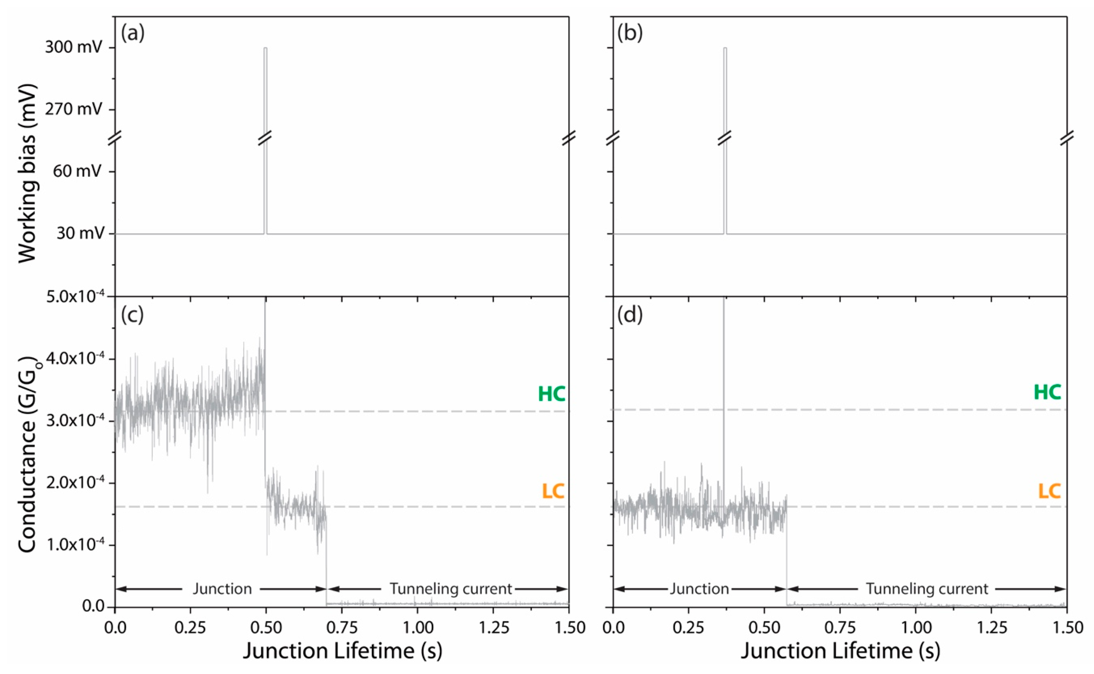
Appendix A.1. In Situ Irreversible High-Conductance (HC) to Low-Conductance (LC) Conversion

To induce HC-to-LC conversion in situ and to study its reversibility [6,52], a high-voltage pulse of 300 mV is applied for 10 ms during the lifetime of a detected HC blink, with the aim to switch the molecular junction to the LC regime (Figure A1a,b). Immediately after the pulse, at Vbias = 30 mV, the detected current decreases to the characteristic LC value (Figure A1c), attesting the Vbias-induced conversion of an individual trapped trans-TMC molecule. Eventually, the junction collapses spontaneously and the current suddenly drops to the It value. Equivalent experiments performed during LC blinks show constant Im profiles independent of the bias pulse, without conversion from LC to HC values (see Figure A1d). Both sets of experiments point to an irreversible HC-to-LC conversion under the experimental conditions.
Figure A1. (a,c) Vbias versus time traces indicating the 10 ms short voltage pulse of 300 mV. (b,d) Conductance versus time traces corresponding to the voltage schemes depicted in (a,c) at a fixed inter-electrode distance of ca. 3 to 3.5 nm.
Applsci 11 03317 g0a1

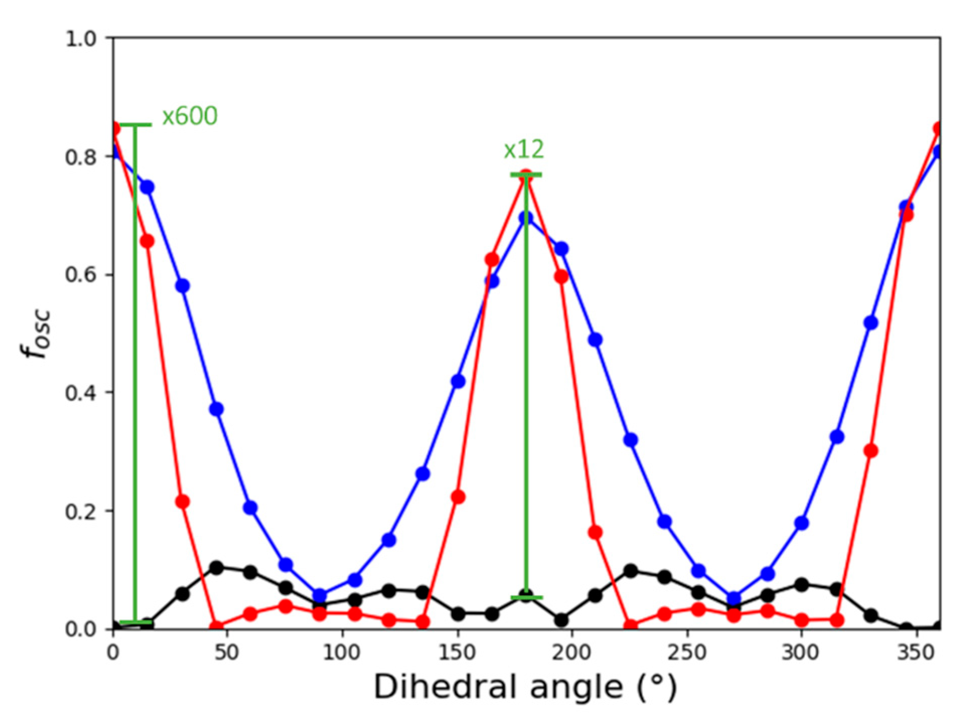
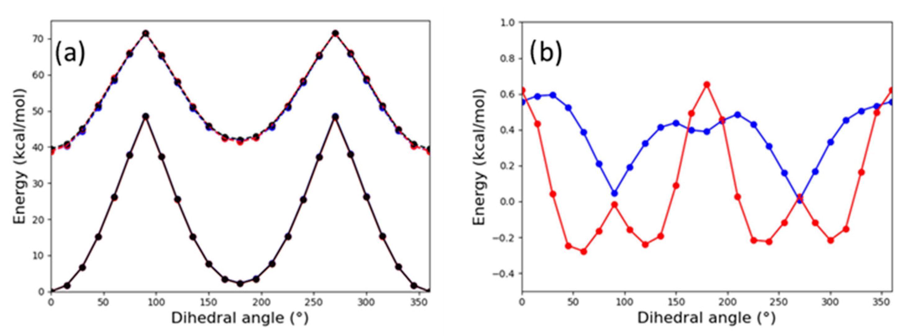
Appendix A.2. Energy Profile for trans-to-cis Rotation in the Absence of an Electric Field

Geometry optimisations for the cis-TMC and trans-TMC configurations reveal that both isomers present a similar energy, with a difference of 0.82 kcal/mol favouring the cis-TMC isomer. Of course, this energy difference is below the typical error of DFT methods, so we can consider both isomers to be of basically the same energy. Starting from the optimized cis-TMC isomer, the dihedral angle connecting both structures was rotated in 15° intervals (Figure A2). The ground state energy profile was insensitive to the addition of an electric field of ±2.2 × 10⁻⁴ atomic units (a.u.), i.e., 1.1 × 10⁸ V/nm, and curves are indistinguishable from the ground state in Figure A3a.
Figure A2. Superposition of structures with θ = 0° (blue), 45°, 90°, 135°, 180° (red). Colour code: S, yellow; C: grey. Hydrogen atoms are omitted for clarity. The structures have not been reoptimized for each studied dihedral angle.
Applsci 11 03317 g0a2
Figure A3. (a) Energy of the ground (solid lines) and first singlet excited (dashed) states along the rotation of the C–C double bond connecting cis-TMC and trans-TMC configurations. (b) Stabilisation of the S1 state due to the inclusion of an EEF of 2.2 × 10⁻⁴ a.u. in the z direction. Blue and red colours correspond to positive and negative signs for the field.
Applsci 11 03317 g0a3
Figure A4. Natural transition orbitals [64] for the S0 → S1 transition of the cis-TMC in the absence (top) or presence (bottom) of an EEF (180° dihedral angle). The weight of each contribution is indicated at the left side.
Applsci 11 03317 g0a4
Table A1. Overlap matrix for the ground state (GS) and 10 lowest singlet excited states (Sn) in the presence and absence of an EEF of +2.2 × 10⁻⁴ a.u. Larger positive and negative contributions are highlighted in blue and red, respectively.
cis-TMC isomer:
GSS1S2S3S4S5S6S7S8S9S10
GS0.99950.00040.0262−0.0148−0.0003−0.0046−0.0004−0.0002−0.0001−0.00030.0001
S1−0.01120.89260.44470.03520.02720.05650.0076−0.01260.00020.00430.0044
S20.02360.4445−0.89250.0177−0.06170.03020.00000.01730.00120.0012−0.0063
S3−0.01400.03330.0324−0.8770−0.47380.0048−0.03020.0462−0.0019−0.00910.0282
S40.0053−0.02300.05900.4740−0.87410.0295−0.0677−0.0331−0.0067−0.0221−0.0137
S50.0042−0.0623−0.0051−0.02300.02850.97130.0093−0.22100.0008−0.00080.0487
S6−0.00030.0046−0.0029−0.00770.0506−0.0064−0.7369−0.0596−0.57870.3402−0.0127
S7−0.00140.0138−0.0203−0.05280.0092−0.2141−0.0937−0.94820.1290−0.1580−0.0343
S8−0.00010.00380.00410.00600.05820.0538−0.63940.21060.4624−0.5703−0.0387
S90.0002−0.0023−0.00010.0049−0.0080−0.0081−0.1834−0.01610.65550.72090.1284
S10−0.0002−0.00160.0081−0.0304−0.00370.05200.01450.01410.07010.1171−0.9886
trans-TMC isomer:
GSS1S2S3S4S5S6S7S8S9S10
GS0.9997−0.0013−0.0217−0.01230.0029−0.00520.0008−0.0013−0.00020.00090.0017
S10.0101−0.83810.5414−0.0248−0.0201−0.05660.01−0.0070.00170.0023−0.0008
S2−0.0192−0.5417−0.8386−0.00410.0462−0.0205−0.01550.0062−0.0006−0.0016−0.0057
S30.0106−0.01780.03020.90640.41840.0022−0.02170.0244−0.0037−0.00040.0314
S4−0.0070.01880.0404−0.41850.9042−0.03090.03750.0506−0.0018−0.0149−0.0064
S5−0.00530.0568−0.01840.0222−0.0287−0.97820.189−0.0427−0.00010.00550.0241
S6−0.00130.0060.0045−0.0190.0511−0.0663−0.5116−0.7544−0.3966−0.03440.0567
S7−0.0002−0.0101−0.01510.02870.00660.17660.829−0.419−0.3031−0.0968−0.0596
S8−0.00090.0002−0.00590.00140.03360.03880.0798−0.48760.80050.33170.0489
S9−0.0016−0.0022−0.0036−0.01670.00050.02210.06520.1119−0.31530.84710.4066
S10−0.0014−0.0049−0.0045−0.0245−0.01190.02930.0488−0.00360.1032−0.40180.9077

Appendix A.3. cis-TMC-syn (Synthetic) Carotenoid Control Experiments

As a control experiment for the trans-to-cis isomerisation process, we employ a homologous cis-TMC isomer control molecule, the cis-TMC-syn (see Figure 1b). The control molecule possesses an almost identical structure to cis-TMC and thus represents a suitable molecular reference to assign the LC feature in (Figure 3) to the cis-isomer. The missing methyl substituents on the phenyl rings on the carotenoid control compared to TMC are not expected to affect significantly the characteristic conductance value of the conjugated carotenoid wire, since CH3- and H-terminal groups exhibit comparable electron-donating character [26].
Unlike for trans-TMC that shows two discrete LC and HC regimes in the dynamic approach, the dynamic BJ cis-TMC-syn experiments exhibit a single (low) conductance value (Figure A5a). cis-TMC-syn yield of 20.3 % and the conductance value of 1.77 × 10⁻³ Go are nearly identical to the analogous concepts for trans-TMC junctions: a yield of 17.4 % and a LC value of 1.68 × 10⁻³ Go. as Figure 2a shows.
Figure A5c–e displays the 2D conductance maps of the cis-TMC-syn at the different applied EEF. Unlike for trans-TMC, cis-TMC-syn junctions show a unique and constant current signature at all three applied Vbias regimes. The molecular conductance value extracted from the blinking approach of 1.60 × 10⁻³ Go is in good agreement with the conductance value obtained from the dynamic approach. The extracted conductance values from the 2D blinking histograms of cis-TMC-syn junctions are statistically identical to those of the LC regimes measured in the trans-TMC at the same Vbias (Figure A6a, blue and orange plots).
Another remarkable similitude between cis-TMC-syn and LC trans-TMC junctions is the observed blinking lifetime that are correlated under equivalent bias regimes (see Figure A6b, blue and orange, respectively). For both measured species, the blinking lifetime is ca. a factor 1.3 larger than that of the HC trans-TMC junctions.
Figure A5. (a) Semi-logarithmic histogram from dynamic experiments for cis-TMC-syn control molecule displaying a single peak of LC fitted with a Gaussian. (b) Representative individual current versus gap distance traces. Vbias = 20 mV. (ce) 2D conductance maps of the cis-TMC-syn control molecule blinking experiments Vbias = (b) 7 mV, (c) 65 mV and (d) 130 mV at a fixed gap distance. Vbias was randomly changed for each set of experiments for a total time of 5h for each bias regime. Counts are normalized to a maximum of 100.
Applsci 11 03317 g0a5
Figure A6. (a) Molecular conductance and (b) blinking lifetimes for trans-TMC HC (green) and LC (orange) as well as for cis-TMC-syn (blue) junctions for the three employed Vbias values. Conductance and standard deviation values are extracted with Gaussian fits of the peaks in 1D blinking histograms of Figure 3 and Figure A5.
Applsci 11 03317 g0a6

Appendix A.4. Synthetic Details

Figure A7. 1H nuclear magnetic resonance (NMR) spectrum for cis-TMC-syn (top) and for trans-TMC (bottom).
Applsci 11 03317 g0a7

References

  1. Nair, V.; Muñoz-Batista, M.J.; Fernández-García, M.; Luque, R.; Colmenares, J.C. Thermo-Photocatalysis: Environmental and Energy Applications. ChemSusChem 2019, 12, 2098–2116. [Google Scholar] [CrossRef]
  2. Shaik, S.; Danovich, D.; Joy, J.; Wang, Z.; Stuyver, T. Electric-Field Mediated Chemistry: Uncovering and Exploiting the Potential of (Oriented) Electric Fields to Exert Chemical Catalysis and Reaction Control. J. Am. Chem. Soc. 2020, 142, 12551–12562. [Google Scholar] [CrossRef]
  3. Tang, C.; Zheng, J.; Ye, Y.; Liu, J.; Chen, L.; Yan, Z.; Chen, Z.; Chen, L.; Huang, X.; Bai, J.; et al. Electric-Field-Induced Connectivity Switching in Single-Molecule Junctions. Science 2020, 23, 100770. [Google Scholar] [CrossRef] [Green Version]
  4. Gorin, C.F.; Beh, E.S.; Kanan, M.W. An Electric Field–Induced Change in the Selectivity of a Metal Oxide–Catalyzed Epoxide Rearrangement. J. Am. Chem. Soc. 2011, 134, 186–189. [Google Scholar] [CrossRef] [PubMed]
  5. Aragonès, A.C.; Haworth, N.L.; Darwish, N.; Ciampi, S.; Bloomfield, N.J.; Wallace, G.G.; Diez-Perez, I.; Coote, M.L. Electrostatic catalysis of a Diels–Alder reaction. Nat. Cell Biol. 2016, 531, 88–91. [Google Scholar] [CrossRef] [PubMed]
  6. Morgenstern, K. Isomerization Reactions on Single Adsorbed Molecules. Accounts Chem. Res. 2009, 42, 213–223. [Google Scholar] [CrossRef] [PubMed]
  7. Kumar, A.S.; Ye, T.; Takami, T.; Yu, B.-C.; Flatt, A.K.; Tour, J.M.; Weiss, P.S. Reversible Photo-Switching of Single Azobenzene Molecules in Controlled Nanoscale Environments. Nano Lett. 2008, 8, 1644–1648. [Google Scholar] [CrossRef] [PubMed]
  8. Mativetsky, J.M.; Pace, G.; Elbing, M.; Rampi, M.A.; Mayor, M.; Samorì, P. Azobenzenes as Light-Controlled Molecular Electronic Switches in Nanoscale Metal−Molecule−Metal Junctions. J. Am. Chem. Soc. 2008, 130, 9192–9193. [Google Scholar] [CrossRef]
  9. Martin, S.; Haiss, W.; Higgins, S.J.; Nichols, R.J. The Impact of EZ Photo-Isomerization on Single Molecular Conductance. Nano Lett. 2010, 10, 2019–2023. [Google Scholar] [CrossRef]
  10. Donhauser, Z.J. Conductance Switching in Single Molecules Through Conformational Changes. Science 2001, 292, 2303–2307. [Google Scholar] [CrossRef] [PubMed]
  11. Ramachandran, G.K.; Tomfohr, J.K.; Li, J.; Sankey, O.F.; Zarate, X.; Primak, A.; Terazono, Y.; Moore, T.A.; Moore, A.L.; Gust, D.; et al. Electron Transport Properties of a Carotene Molecule in a Metal−(Single Molecule)−Metal Junction. J. Phys. Chem. B 2003, 107, 6162–6169. [Google Scholar] [CrossRef]
  12. Venkataraman, L.; Klare, J.E.; Nuckolls, C.; Hybertsen, M.S.; Steigerwald, M.L. Dependence of single-molecule junction conductance on molecular conformation. Nat. Cell Biol. 2006, 442, 904–907. [Google Scholar] [CrossRef] [PubMed] [Green Version]
  13. Tao, N.J. Electron transport in molecular junctions. Nat. Nanotechnol. 2006, 1, 173–181. [Google Scholar] [CrossRef]
  14. Cai, Z.-L.; Crossley, M.J.; Reimers, J.R.; Kobayashi, A.R.; Amos, R.D. Density Functional Theory for Charge Transfer: The Nature of the N-Bands of Porphyrins and Chlorophylls Revealed through CAM-B3LYP, CASPT2, and SAC-CI Calculations. J. Phys. Chem. B 2006, 110, 15624–15632. [Google Scholar] [CrossRef]
  15. Leary, E.; Roche, C.; Jiang, H.-W.; Grace, I.; González, M.T.; Rubio-Bollinger, G.; Romero-Muñiz, C.; Xiong, Y.; Al-Galiby, Q.; Noori, M.; et al. Detecting Mechanochemical Atropisomerization within an STM Break Junction. J. Am. Chem. Soc. 2018, 140, 710–718. [Google Scholar] [CrossRef] [Green Version]
  16. Li, J.; Tomfohr, J.K.; Sankey, O.F. Theoretical study of carotene as a molecular wire. Phys. E Low Dimens. Syst. Nanostructures 2003, 19, 133–138. [Google Scholar] [CrossRef]
  17. Del Valle, M.; Gutierrez, R.; Tejedor, C.; Cuniberti, G. Tuning the conductance of a molecular switch. Nat. Nanotechnol. 2007, 2, 176–179. [Google Scholar] [CrossRef] [Green Version]
  18. Dhivya, G.; Nagarajan, V.; Chandiramouli, R. First-principles studies on switching properties of azobenzene based molecular device. Chem. Phys. Lett. 2016, 660, 27–32. [Google Scholar] [CrossRef]
  19. Li, C.; Pobelov, I.; Wandlowski, T.; Bagrets, A.; Arnold, A.A.; Evers, F. Charge Transport in Single Au | Alkanedithiol | Au Junctions: Coordination Geometries and Conformational Degrees of Freedom. J. Am. Chem. Soc. 2008, 130, 318–326. [Google Scholar] [CrossRef] [Green Version]
  20. Cao, Y.; Dong, S.; Liu, S.; Liu, Z.; Guo, X. Toward Functional Molecular Devices Based on Graphene-Molecule Junctions. Angew. Chem. Int. Ed. 2013, 52, 3906–3910. [Google Scholar] [CrossRef]
  21. Sotthewes, K.; Geskin, V.; Heimbuch, R.; Kumar, A.; Zandvliet, H.J.W. Research Update: Molecular electronics: The single-molecule switch and transistor. APL Mater. 2014, 2, 10701. [Google Scholar] [CrossRef]
  22. Kim, M.; Jung, H.; Aragonès, A.C.; Diez-Perez, I.; Ahn, K.-H.; Chung, W.-J.; Kim, D.; Koo, S. Role of Ring Ortho Substituents on the Configuration of Carotenoid Polyene Chains. Org. Lett. 2018, 20, 493–496. [Google Scholar] [CrossRef]
  23. Schwarz, F.; Lörtscher, E. Break-junctions for investigating transport at the molecular scale. J. Phys. Condens. Matter 2014, 26, 474201. [Google Scholar] [CrossRef] [PubMed]
  24. Komoto, Y.; Fujii, S.; Iwane, M.; Kiguchi, M. Single-molecule junctions for molecular electronics. J. Mater. Chem. C 2016, 4, 8842–8858. [Google Scholar] [CrossRef]
  25. Stefani, D.; Perrin, M.; Gutiérrez-Cerón, C.; Aragonès, A.C.; Labra-Muñoz, J.; Carrasco, R.D.C.; Matsushita, Y.; Futera, Z.; Labuta, J.; Ngo, T.H.; et al. Mechanical Tuning of Through-Molecule Conductance in a Conjugated Calix[4]pyrrole. Chemitry 2018, 3, 6473–6478. [Google Scholar] [CrossRef]
  26. Aragonès, A.C.; Darwish, N.; Im, J.; Lim, B.; Choi, J.; Koo, S.; Díez-Pérez, I. Fine-Tuning of Single-Molecule Conductance by Tweaking Both Electronic Structure and Conformation of Side Substituents. Chem. A Eur. J. 2015, 21, 7716–7720. [Google Scholar] [CrossRef]
  27. Chen, F.; Tao, N.J. Electron Transport in Single Molecules: From Benzene to Graphene. Accounts Chem. Res. 2009, 42, 429–438. [Google Scholar] [CrossRef]
  28. Li, X.; He, J.; Hihath, J.; Xu, B.; Lindsay, S.M.; Tao, N. Conductance of Single Alkanedithiols: Conduction Mechanism and Effect of Molecule−Electrode Contacts. J. Am. Chem. Soc. 2006, 128, 2135–2141. [Google Scholar] [CrossRef]
  29. Kushmerick, J.G.; Holt, D.B.; Pollack, S.K.; Ratner, M.A.; Yang, J.C.; Schull, T.L.; Naciri, J.; Moore, M.H.; Shashidhar, R. Effect of Bond-Length Alternation in Molecular Wires. J. Am. Chem. Soc. 2002, 124, 10654–10655. [Google Scholar] [CrossRef] [PubMed]
  30. Tracewell, C.A.; Cua, A.; Stewart, D.H.; Bocian, D.F.; Brudvig, G.W. Characterization of Carotenoid and Chlorophyll Photooxidation in Photosystem II. Biochemitry 2001, 40, 193–203. [Google Scholar] [CrossRef] [PubMed]
  31. Tracewell, C.A.; Brudvig, G.W. Multiple Redox-Active Chlorophylls in the Secondary Electron-Transfer Pathways of Oxygen-Evolving Photosystem II. Biochemitry 2008, 47, 11559–11572. [Google Scholar] [CrossRef] [PubMed] [Green Version]
  32. Garner, M.H.; Solomon, G.C. Simultaneous Suppression of π- and σ-Transmission in π-Conjugated Molecules. J. Phys. Chem. Lett. 2020, 11, 7400–7406. [Google Scholar] [CrossRef] [PubMed]
  33. Hunter, J.D. Matplotlib: A 2D Graphics Environment. Comput. Sci. Eng. 2007, 9, 90–95. [Google Scholar] [CrossRef]
  34. Neese, F. Software update: The ORCA program system, version 4.0. Wiley Interdiscip. Rev. Comput. Mol. Sci. 2018, 8, 8. [Google Scholar] [CrossRef]
  35. Runge, E.; Gross, E.K.U. Density-Functional Theory for Time-Dependent Systems. Phys. Rev. Lett. 1984, 52, 997–1000. [Google Scholar] [CrossRef]
  36. Becke, A.D. Density-functional exchange-energy approximation with correct asymptotic behavior. Phys. Rev. A 1988, 38, 3098–3100. [Google Scholar] [CrossRef]
  37. Perdew, J.P. Density-functional approximation for the correlation energy of the inhomogeneous electron gas. Phys. Rev. B 1986, 33, 8822–8824. [Google Scholar] [CrossRef]
  38. Weigend, F.; Ahlrichs, R. Balanced basis sets of split valence, triple zeta valence and quadruple zeta valence quality for H to Rn: Design and assessment of accuracy. Phys. Chem. Chem. Phys. 2005, 7, 3297–3305. [Google Scholar] [CrossRef]
  39. Weigend, F. Accurate Coulomb-fitting basis sets for H to Rn. Phys. Chem. Chem. Phys. 2006, 8, 1057–1065. [Google Scholar] [CrossRef]
  40. Grimme, S.; Antony, J.; Ehrlich, S.; Krieg, H. A consistent and accurate ab initio parametrization of density functional dispersion correction (DFT-D) for the 94 elements H-Pu. J. Chem. Phys. 2010, 132, 154104. [Google Scholar] [CrossRef] [Green Version]
  41. Grimme, S.; Ehrlich, S.; Goerigk, L. Effect of the damping function in dispersion corrected density functional theory. J. Comput. Chem. 2011, 32, 1456–1465. [Google Scholar] [CrossRef]
  42. Plasser, F.; Ruckenbauer, M.; Mai, S.; Oppel, M.; Marquetand, P.; González, L. Efficient and Flexible Computation of Many-Electron Wave Function Overlaps. J. Chem. Theory Comput. 2016, 12, 1207–1219. [Google Scholar] [CrossRef] [PubMed]
  43. Chen, F.; Li, X.; Hihath, J.; Huang, Z.; Tao, N. Effect of Anchoring Groups on Single-Molecule Conductance: Comparative Study of Thiol-, Amine-, and Carboxylic-Acid-Terminated Molecules. J. Am. Chem. Soc. 2006, 128, 15874–15881. [Google Scholar] [CrossRef] [PubMed]
  44. Haiss, W.; Nichols, R.J.; Van Zalinge, H.; Higgins, S.J.; Bethell, D.; Schiffrin, D.J. Measurement of single molecule conductivity using the spontaneous formation of molecular wires. Phys. Chem. Chem. Phys. 2004, 6, 4330–4337. [Google Scholar] [CrossRef]
  45. Pla-Vilanova, P.; Aragonès, A.C.; Ciampi, S.; Sanz, F.; Darwish, N.; Diez-Perez, I. The spontaneous formation of single-molecule junctions via terminal alkynes. Nanotechnology 2015, 26, 381001. [Google Scholar] [CrossRef] [PubMed]
  46. Aragonès, A.C.; Darwish, N.; Ciampi, S.; Sanz, F.; Gooding, J.J.; Díez-Pérez, I. Single-molecule electrical contacts on silicon electrodes under ambient conditions. Nat. Commun. 2017, 8, 15056. [Google Scholar] [CrossRef]
  47. Xu, B. Measurement of Single-Molecule Resistance by Repeated Formation of Molecular Junctions. Science 2003, 301, 1221–1223. [Google Scholar] [CrossRef] [PubMed] [Green Version]
  48. Li, Z.; Han, B.; Meszaros, G.; Pobelov, I.; Wandlowski, T.; Błaszczyk, A.; Mayor, M. Two-dimensional assembly and local redox-activity of molecular hybrid structures in an electrochemical environment. Faraday Discuss. 2005, 131, 121–143. [Google Scholar] [CrossRef] [Green Version]
  49. Bruot, C.; Hihath, J.; Tao, N. Mechanically controlled molecular orbital alignment in single molecule junctions. Nat. Nanotechnol. 2011, 7, 35–40. [Google Scholar] [CrossRef] [PubMed]
  50. Inatomi, J.; Fujii, S.; Marqués-González, S.; Masai, H.; Tsuji, Y.; Terao, J.; Kiguchi, M. Effect of Mechanical Strain on Electric Conductance of Molecular Junctions. J. Phys. Chem. C 2015, 119, 19452–19457. [Google Scholar] [CrossRef]
  51. Qi, J.; Gao, Y.; Jia, H.; Richter, M.; Huang, L.; Cao, Y.; Yang, H.; Zheng, Q.; Berger, R.; Liu, J.; et al. Force-Activated Isomerization of a Single Molecule. J. Am. Chem. Soc. 2020, 142, 10673–10680. [Google Scholar] [CrossRef]
  52. Alemani, M.; Peters, M.V.; Hecht, S.; Rieder, K.-H.; Moresco, A.F.; Grill, L. Electric Field-Induced Isomerization of Azobenzene by STM. J. Am. Chem. Soc. 2006, 128, 14446–14447. [Google Scholar] [CrossRef] [PubMed]
  53. Zang, Y.; Zou, Q.; Fu, T.; Ng, F.; Fowler, B.; Yang, J.; Li, H.; Steigerwald, M.L.; Nuckolls, C.; Venkataraman, L. Directing isomerization reactions of cumulenes with electric fields. Nat. Commun. 2019, 10, 1–7. [Google Scholar] [CrossRef] [PubMed]
  54. Huang, Z.; Chen, F.; D’Agosta, R.; Bennett, P.A.; Di Ventra, M.; Tao, N. Local ionic and electron heating in single-molecule junctions. Nat. Nanotechnol. 2007, 2, 698–703. [Google Scholar] [CrossRef] [PubMed]
  55. Blum, A.S.; Kushmerick, J.G.; Long, D.P.; Patterson, C.H.; Yang, J.C.; Henderson, J.C.; Yao, Y.; Tour, J.M.; Shashidhar, R.; Ratna, B.R. Molecularly inherent voltage-controlled conductance switching. Nat. Mater. 2005, 4, 167–172. [Google Scholar] [CrossRef] [PubMed]
  56. Diez-Perez, I.; Hihath, J.; Hines, T.; Wang, Z.-S.; Zhou, G.; Müllen, K.; Tao, N. Controlling single-molecule conductance through lateral coupling of π orbitals. Nat. Nanotechnol. 2011, 6, 226–231. [Google Scholar] [CrossRef]
  57. Kitaguchi, Y.; Habuka, S.; Okuyama, H.; Hatta, S.; Aruga, T.; Frederiksen, T.; Paulsson, M.; Ueba, H. Controlling single-molecule junction conductance by molecular interactions. Sci. Rep. 2015, 5, 11796. [Google Scholar] [CrossRef] [Green Version]
  58. Yoshida, K.; Pobelov, I.V.; Manrique, D.Z.; Pope, T.; Mészáros, G.; Gulcur, M.; Bryce, M.R.; Lambert, C.J.; Wandlowski, T. Correlation of breaking forces, conductances and geometries of molecular junctions. Sci. Rep. 2015, 5, srep09002. [Google Scholar] [CrossRef] [Green Version]
  59. Reckien, W.; Eggers, M.; Bredow, T. Theoretical study of the adsorption of benzene on coinage metals. Beilstein J. Org. Chem. 2014, 10, 1775–1784. [Google Scholar] [CrossRef] [Green Version]
  60. Meisner, J.S.; Ahn, S.; Aradhya, S.V.; Krikorian, M.; Parameswaran, R.; Steigerwald, M.; Venkataraman, L.; Nuckolls, C. Importance of Direct Metal−π Coupling in Electronic Transport Through Conjugated Single-Molecule Junctions. J. Am. Chem. Soc. 2012, 134, 20440–20445. [Google Scholar] [CrossRef]
  61. Roke, D.; Wezenberg, S.J.; Feringa, B.L. Molecular rotary motors: Unidirectional motion around double bonds. Proc. Natl. Acad. Sci. USA 2018, 115, 9423–9431. [Google Scholar] [CrossRef] [PubMed] [Green Version]
  62. Hall, C.R.; Conyard, J.; Heisler, I.A.; Jones, G.A.; Frost, J.; Browne, W.R.; Feringa, B.L.; Meech, S.R. Ultrafast Dynamics in Light-Driven Molecular Rotary Motors Probed by Femtosecond Stimulated Raman Spectroscopy. J. Am. Chem. Soc. 2017, 139, 7408–7414. [Google Scholar] [CrossRef] [Green Version]
  63. Pang, X.; Cui, X.; Hu, D.; Jiang, C.; Zhao, D.; Lan, Z.; Li, F. “Watching” the Dark State in Ultrafast Nonadiabatic Photoisomerization Process of a Light-Driven Molecular Rotary Motor. J. Phys. Chem. A 2017, 121, 1240–1249. [Google Scholar] [CrossRef] [PubMed]
  64. Martin, R.L. Natural transition orbitals. J. Chem. Phys. 2003, 118, 4775–4777. [Google Scholar] [CrossRef]
  65. Kazaryan, A.; Lan, Z.; Schäfer, L.V.; Thiel, W.; Filatov, M. Surface Hopping Excited-State Dynamics Study of the Photoisomerization of a Light-Driven Fluorene Molecular Rotary Motor. J. Chem. Theory Comput. 2011, 7, 2189–2199. [Google Scholar] [CrossRef] [PubMed] [Green Version]
Figure 1. (a) Trans-TMC (terminal 1,5-dimethyl-3-methylthiophenyl) and (b) cis-TMC-syn synthesized molecules. (c) Schematic of the dynamic BJ approach: (1) current saturation; tip and substrate in contact, (2) current plateau at Istep due to the formation of a molecular junction during tip retraction, (3) zero current (junction breakdown) stage when the tip is pulled away from the surface and the molecule detaches from one electrode. (d) Schematic of the blinking approach: (1) fixed inter-electrode distance, d, at a pre-defined tunnelling current, It. (2) current blink at, Im due to the spontaneous formation of a molecular junction (with a finite lifetime τ), (3) current drop to It upon spontaneous molecular junction breakdown.
Applsci 11 03317 g001
Figure 2. (a) Semi-logarithmic histogram from dynamic break junction (BJ) experiments for trans-TMC displaying a high conductance peak (HC, green traces) and a low conductance peak (LC, orange traces) fitted with Gaussians. (b) Representative individual current versus gap distance traces. Vbias = 20 mV.
Applsci 11 03317 g002
Figure 3. (a) Representative HC (green) and LC (orange) blinks of the trans-TMC junction formation in a typical static BJ experiment. 2D conductance maps built out of hundreds of trans-TMC blinking traces at Vbias = (b) 7 mV, (c) 65 mV, and (d) 130 mV at a fixed gap distance. Counts are normalized to a maximum of 100.
Applsci 11 03317 g003
Figure 4. Oscillator strength for the S0 → S1 transition. Black, blue, and red colours correspond to external electric fields (EEF) = 0, +2.3 × 10⁻⁴ a.u. and −2.3 × 10⁻⁴ a.u., respectively. Note the strength difference in the enhancement of the oscillator between trans-TMC and cis-TMC conformers (a factor of 12 and 600, respectively).
Applsci 11 03317 g004
Figure 5. Orbitals for the S0 → S1 natural transition of the trans-TMC in the absence (top) or presence (bottom) of an EEF (0° dihedral angle). Left numerical column indicates the weight for each orbital.
Applsci 11 03317 g005
Publisher’s Note: MDPI stays neutral with regard to jurisdictional claims in published maps and institutional affiliations.

