Multigap Resistive Plate Chambers for Time of Flight Applications

Key Laboratory of Particle and Radiation Imaging, Department of Engineering Physics, Tsinghua University, Beijing 100084, China
*
Author to whom correspondence should be addressed.
Appl. Sci. 2021, 11(1), 111; https://doi.org/10.3390/app11010111
Submission received: 9 November 2020
/
Revised: 8 December 2020
/
Accepted: 15 December 2020
/
Published: 24 December 2020
(This article belongs to the Special Issue Development and Application of Particle Detectors)
Abstract
:With the advantages of high-performance, easy to build and relatively low cost, the multigap resistive plate chamber has been arousing broad interests over the last few decades. It has become a new standard technology for the time of flight system in high energy physics experiments. In this article, we will give a description of the structure and the operating principles of the MRPC detector and focus on reviewing the applications on the time of flight system in several famous experiments. The performances, including time resolution and particle identification, are discussed in detail. Some recent advances and points of view for the future development of the next generation MRPC are also outlined.
1. Introduction
To reveal many aspects of the physics program, techniques of particle identification (PID) [1] are the key requirements in particle and high energy physics experiments. Different particles can be identified through one or several combined detector systems to measure their mass or how they interact with matter. More details can be found in [1]. Among them, the time of flight (ToF) system is an essential part, especially for identifying hadrons. The ToF system can provide the velocity information of the charged particle by measuring the traveling time of a given distance . Combined with the momentum obtained from the magnetic spectrometer, the mass of the particle, as a basis for identification, can be calculated:
If we want to identify particles with the same momentum, their flight time difference can be obtained according to Equation (2):
The separation power (), used to evaluate the reliability of separation, is defined as the ratio of the flight time difference and standard deviations. Usually is required in many experiments. Assuming , it can be derived and given by:
where is the time resolution of the ToF.
There are many candidate detectors that can be considered for the construction of the ToF system. In the early 1990 s, the parallel plate chambers (PPC) [2,3], a gaseous detector with only one gas gap between two metallic electrodes, were investigated for possible use at the LHC. However, because its gas gain must be kept low to maintain its avalanche mode, which leads to difficulty with both a high-efficiency (<90%) and a good timing resolution (>250 ps), it wouldn’t be considered nowadays.
For advances in ToF techniques, the fast photon detectors have been considered and had major improvements. Scintillators with photomultipliers are frequently used because of their excellent time resolution. For example, the LIDAL system [4] use fast plastic scintillators coupled with photomultiplier tubes (PMTs) to perform ToF measurements. The beam test results have demonstrated that a time resolution below 100 ps can be achieved. A systematic test of several medium-sized plastic scintillators [5] has shown a time resolution below 10 ps. However, the light yield of scintillators [6] will change under different magnetic fields; the magnetic field tolerance of PMTs demands careful consideration due to the effect of both electric and magnetic field on the trajectories of electrons; the scintillators are challenging to be highly segmented in order to determine the hit multiplicity; the particle experiments are usually large in size, and the PMTs are high-priced.
Over the years, Si-based technologies have gained much attention. For example, silicon photomultipliers (SiPMs) [7,8,9] are indeed replacing the standard PMTs and are playing a vital role in future collider experiments [10] like the high luminosity large hadron collider (HL-LHC) [11] or medical applications like TOF-PET [12,13] thanks to the many advantages: a higher efficiency, lower bias voltage, higher segmentation and insensitivity to magnetic fields. Moreover, low gain avalanche diodes (LGAD) [14], which are n-on-p silicon sensors with internal charge multiplication, have shown a time resolution of better than 20 ps. The ATLAS and CMS experiments [15,16] are designing LGAD detectors to address the good timing measurements and pile-up challenge at the HL-LHC.
A detector based on MCP-PMTs (microchannel plate PMTs) [17] is a promising solution for the fast timing of single photon signals. Coupled with a quartz Cherenkov radiator, it can provide ~10 ps time resolution [18,19]. The LQbar detector based on MCP-PMT [20] is intended for the LHC pp-diffraction scattering experiment. However, issues like high costs and crosstalk between anodes need to be further studied to significantly progress this ToF technique.
Multigap resistive plate chamber (MRPC) is a relatively new and standard technology for the ToF system. It is known for very high detection efficiency (>95%), excellent time resolution (<100 ps) and relatively low cost. This detector is easy to build and possible to cover a large area. It has been extensively employed as a ToF system in many nuclear physics experiments, such as BESIII [21], ALICE [22,23,24], CBM [25,26], STAR [27,28,29] and PHENIX [30].
This review will focus on the multigap resistive plate chamber (MRPC) and its applications as a ToF detector in large experiments. The description and detector physics of MRPC are introduced in Section 2. Its applications in current large experiments and developments for future ToF systems are discussed in Section 3.
2. Description of MRPC Detector
In the 1980 s, Santonico [31] built the first prototype of the RPC, which can be considered to substitute resistive electrodes for the metallic electrodes of the PPC detector. The use of resistive electrodes is a major improvement, which allows the detector to operate continuously (no need for pulsed HV (High Voltage) for discharge quenching) and restricts discharges to a local area (the rest remains active). Unlike the early gas detectors, the high voltage electrodes of RPC are separated from the signal readout electrodes. The carbon film attached to the resistive electrode is used as the high voltage electrode and the conductive material as the readout electrode. The choice of resistive electrode materials is crucial. On one hand, it is not supposed to affect the generation of induced signals due to the movement of charge, which requires the resistive plate to have relatively high resistance. Thus, the discharge durations (~10 ns) are far less than the characteristic time constant (). Macroscopically, the resistive electrodes are called “transparent” to the induced signals. On the other hand, the counting rate of the detector is related to the time that the resistive electrode needs to recover and charge up again, which depends on the resistivity of the electrode. Excessive resistivity will increase the detector’s dead time and decrease the detector’s counting rate capability. Thus, RPC detectors generally adopt glass or Bakelite as the resistive material, whose volume resistivity is usually within the range of – cm.
For trigger applications, typical RPCs can operate at around 95% efficiency with a time resolution of sub-ns and at a counting rate of hundreds of Hz/cm2. Considering one primary electron created somewhere in one gas gap, Riegler [32] derived a nice formula to estimate the intrinsic time resolution for one-gap RPC:
where is the electron drift velocity, the Townsend coefficient (=1/lambda, lambda is the mean distance between ionizing collisions), and the attachment coefficient. They are mainly determined by the gas mixture and working electric field. To improve the time resolution for timing measurements, the effective approach is to decrease the gap width as much as possible so that the electric field can be greatly increased under the avalanche working mode. Hence, the effective Townsend coefficient is much higher, and the electron drift velocity is much faster. To maintain the efficiency and improve the performance of normal RPCs, more gas gaps are introduced to increase the total gap thickness of the detector and the number of primary electrons. Consequently, the multigap RPC [33] was developed by M.C.S. Williams.
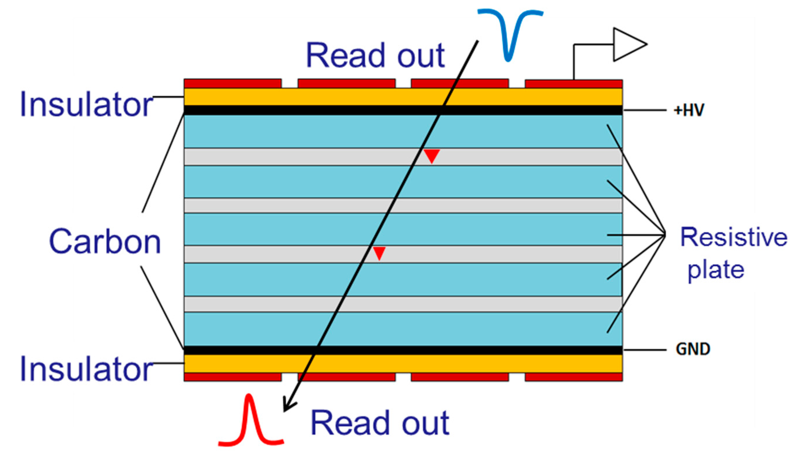
As shown in Figure 1, several equally spaced resistive plates are placed so that small gaps can be created. Commonly nylon fishing lines are used to confirm a uniform gap width. Thus, the avalanche is limited to a small space, and the electric field can be increased, which leads to a much better time resolution. The high voltage is just applied to the graphite layer coated on the outer resistive plates of each stack, while the intermediate resistive plates are allowed to float electrically. Moreover, to separate the high voltage electrodes from the readout electrodes, a thin insulating layer of Mylar is used and glued on the printed circuit board (PCB) copper layer. The honeycomb boards are attached to the top and bottom to support the whole detector. The core part of an MRPC is the working gas in the gaps. Usually, the MRPC detector works in avalanche mode. To suppress the growth of the avalanche in the high electric field, some electronegative gases are added to increase the attachment coefficient. For example, the commonly used gas mixture consists of a large part (even up to 90%) of tetrafluoroethane (C2H2F4) with a few percentages of isobutane (i-C4H10) and sulfur hexafluoride (SF6).
Even though the detector’s geometry is simple, as shown above, the physics in MRPCs is quite complicated. The incident particles will interact with the gas molecules in the MRPC detector. Each interaction will deposit a certain amount of energy, which will cause the ionization of extranuclear electrons and generate clusters of primary electron-ion pairs. Each cluster contains one or more electrons, the number of which depends on how much energy is deposited during the collision of the incident particles. The electrons generated by ionization will drift towards the anode under the high electric field, while the positive ions will drift towards the cathode. In the process of drifting towards the anode, the electrons will obtain energy from the electric field and trigger secondary ionization. Similarly, the secondary ionized particles are accelerated again and trigger new ionization. Here is the cascade of electron multiplications known as Townsend avalanches [34]. When the number of electrons in a cluster is large enough, the aggregation of electrons will create a considerable local field, whose magnitude is comparable to the applied field but in the opposite direction. At this time, the avalanche will saturate and stop growing, which is called the “space charge effect” [35]. The diffusion effect [36], due to collisions between electrons/ions and the gas molecules, should be discussed for the real conditions. More details about the detector physics and simulation can be found in [32,37,38].
As ionized electrons and ions move in the gas gap, a time-varying current signal will be induced on the PCB’s readout strips or pads. The induced current signal [39] can be derived by Ramo’s theorem [40] and given by:
where is the number of electrons at time , is the electron charge, is the drift velocity which can be simulated by Magboltz, (weighting field) is the electric field obtained by setting the selected electrode to potential and others to 0.
Once the currents induced on the electrodes have been calculated, and all the resistive, capacitive and inductive elements of the MRPC system have been introduced, the final currents can be determined [41], and detailed discussions about the signal propagation and signal integrity can be found in [42,43,44]. For the multi-conductor transmission lines readout structure in MRPCs, the impedance [45,46] has been well studied through experimental tests and simulations to help achieve impedance matching with the electronics and optimize the detector structure. An approximate formula for the impedance of a multi-stack MRPC [46] is given by:
where is the number of gas gaps in a stack, the number of stacks, the glass thickness, the gap thickness and the strip width. Considering the inhomogeneous dielectric mediums between the paired strips of the MRPC, the equivalent dielectric constant can be estimated as follows:
where the relative dielectric constant of the gas () is set to 1, and is the relative dielectric constant of the glass. One can know the impedance of the readout strips before designing an MRPC detector, leading to significant time and cost savings.
3. Applications in Large Experiments
Since the early 2000s, MRPCs have been carefully investigated and have become the new standard ToF technology, as seen in many physics experiments. Several typical experiments, such as STAR, CBM and SoLID, and their MRPC-based ToF will be reviewed in this section. The detailed configurations and working performances of MRPC detectors in each ToF system will also be elaborated.
3.1. STAR Experiment in RHIC
The solenoidal tracker at the relativistic heavy ion collider (RHIC) [47], known as STAR [48], is dedicated to searching for the quark-gluon plasma (QGP) that existed in the early universe. It utilizes a large cylindrical time-projection chamber (TPC) with a large solenoid magnet, providing a close to 4 angle tracking capability for charged particles from collisions. The full-acceptance MRPC-based ToF system [49] was proposed to extend STAR’s PID capability.
3.1.1. The STAR MRPC
The structure of the STAR MRPC module is demonstrated in Figure 2. This MRPC has 6 gaps of 0.22 mm-thick in a single stack. It is assembled with float glasses of typical resistivity on the order of cm. The thickness of the inner and outer glass sheets are 0.54 and 0.7 mm, respectively. It operates in avalanche mode with a gas mixture of 95% C2H2F4 and 5% i-C4H10. The working field is around 106 kV/cm.
The differential signals of each module are read out by six pads, each of 3.1 × 6.0 cm2, and amplified by NINO chip [50,51] developed at CERN, which is an ultrafast and high-performance chip with a rising edge of 1 ns, the low power consumption of 30 mW/channel and a time resolution of 20 ps. The CERN HPTDC ASIC [52,53,54] is chosen to be the data acquisition system (DAQ). Its time resolution is around 25 ps.
3.1.2. The STAR-ToF System
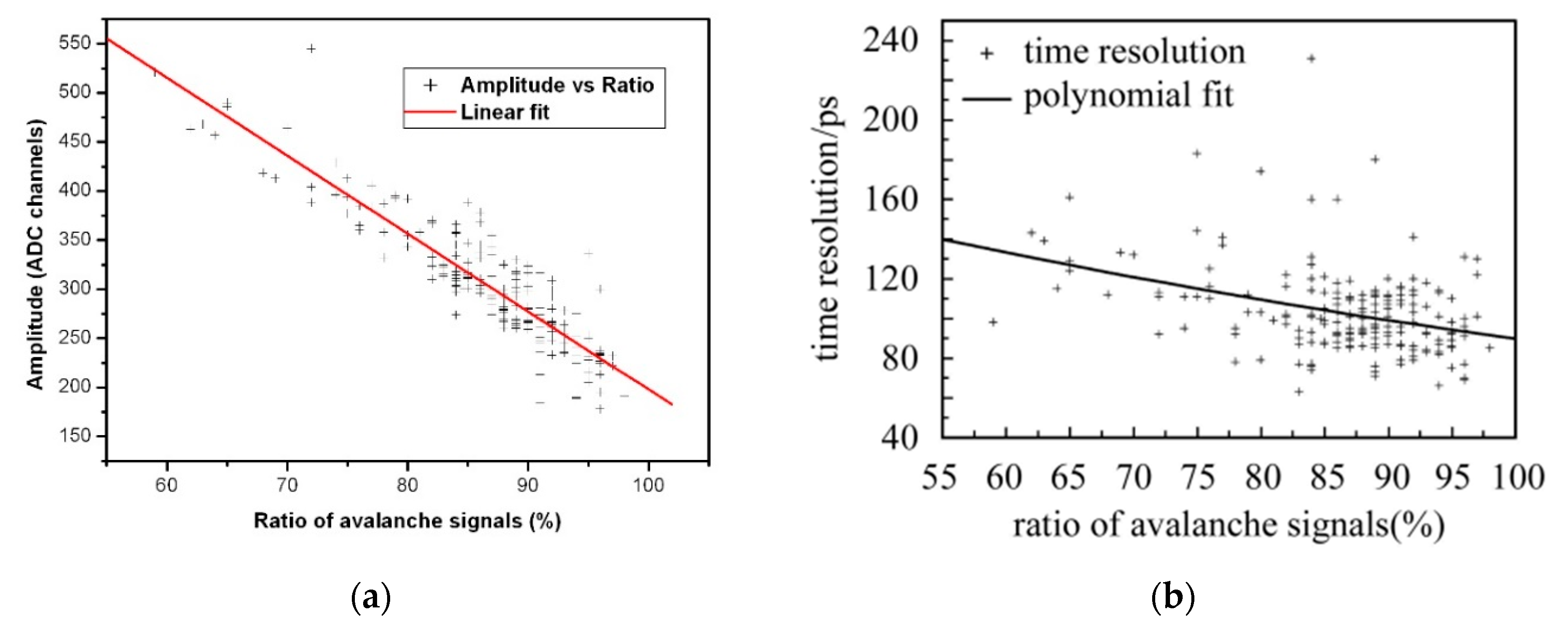
The cylindrical ToF consists of 120 trays, each of 32 MRPCs. Tsinghua University is in charge of a majority of the MRPC production. To assure the quality of MRPC modules, a rigid set of manufacturing criteria and quality assurance (QA) procedures [29] are set up. Specifications of the dimensions and materials have been controlled strictly, and the characteristics such as dark current, noise rate, efficiency and time resolution have been validated. Moreover, the avalanche ratio, the ratio of avalanche to streamers, is found to be related to the amplitude and time resolution. A high fraction of streamers will worsen the time resolution, as shown in Figure 3. Therefore, the avalanche ratio is specified to be larger than 80% to maintain the detector’s performance and save the QA time. Beam tests [28] at CERN showed that the overall time resolution after time slewing correction could reach 60 ps, and an efficiency of 97% was achieved.
The R&D and production of STAR-ToF were started in 2000 and completed in 2009. The final trays [55] ran stably in different physics runs. The overall start and stop time resolutions are reported in Table 1. The pseudo vertex position detector (pVPD) [56] records the event start time, while the ToF system provides the stop times. Earlier runs 3–5 are the initial tests of the MRPC prototypes, while run 8 and run 9 are for the final system trays. From run 5, the rising and falling times of a signal are recorded by HPTDC and the time slewing effects are corrected according to the time over threshold (ToT) values instead of the signal amplitude for earlier runs. The time resolutions of the final system trays are below 80 ps, which meets the physics requirement.
3.1.3. The PID Performance
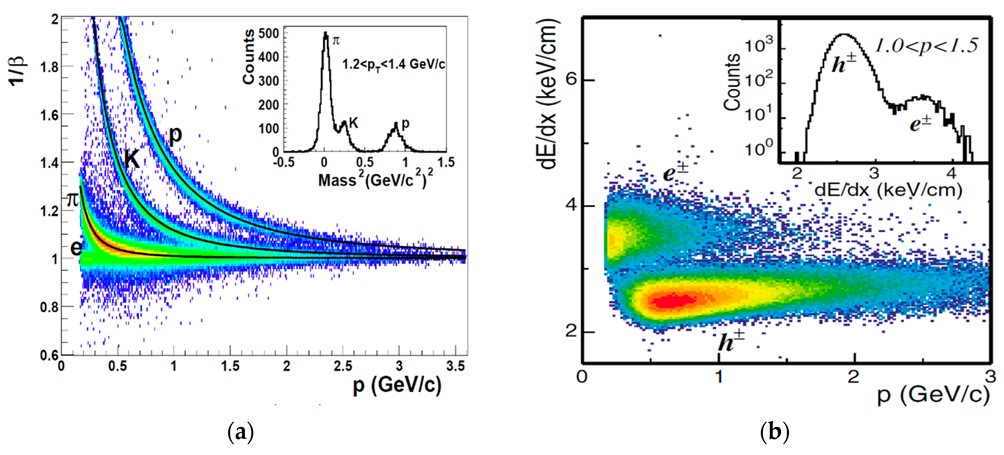
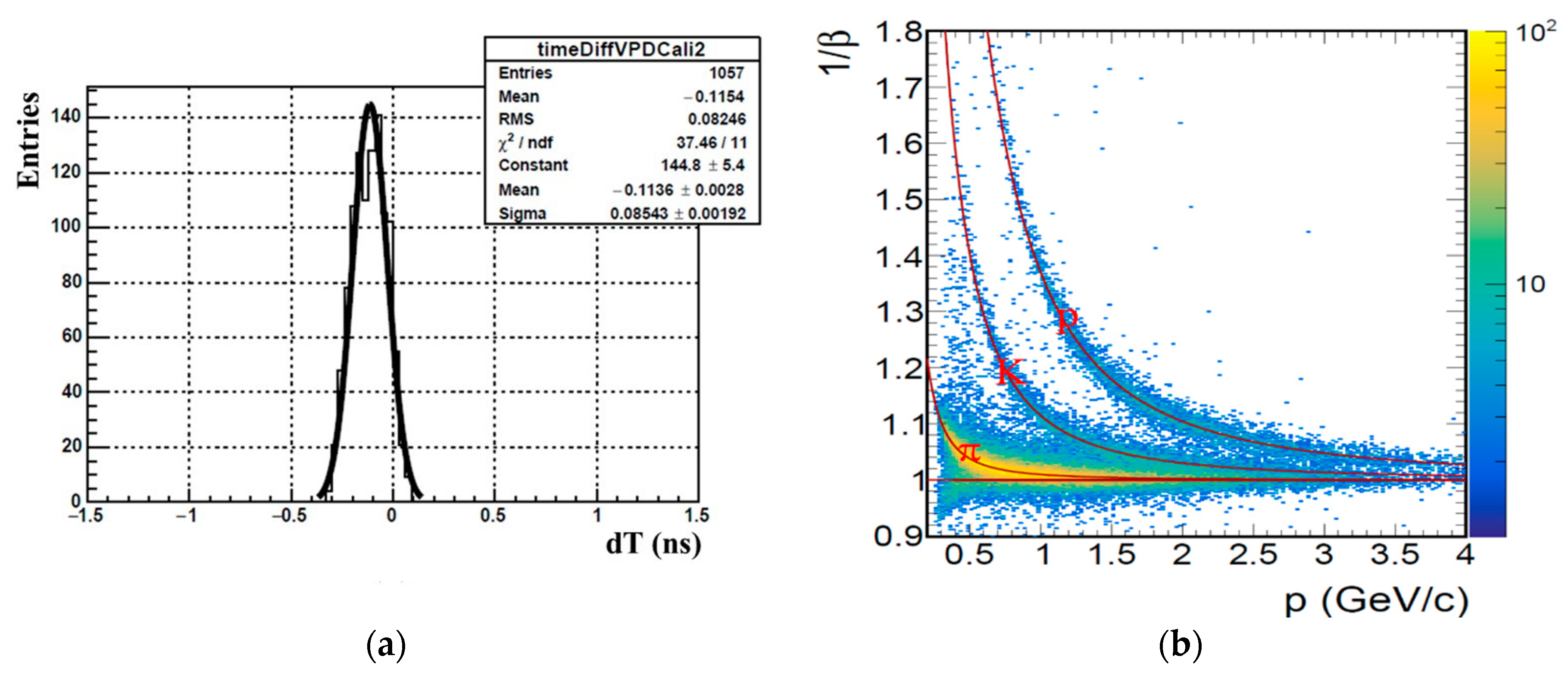
In the 200 GeV d + Au collisions, the average MRPC ToF timing resolution alone was measured to be 85 ps. The tracks of passing particles were reconstructed by the TPC, and their momentum and dE/dx were also recorded. Then the particle path can be calculated and extended to the ToF system. Figure 4a [57] shows the relationship between the inversed velocity (1/β) measured by the ToF system and the momentum (p) obtained from TPC. The ToF provides good PID capabilities with 1.6 GeV/c for π/K and 3 GeV/c for K/p separation. The embedded pad shows the distribution of the square of the mass for momentum in the range of 1.2 and 1.4 GeV/c. The pions, kaons and protons can be distinguished clearly. Furthermore, it makes the separation between electrons and hadrons possible with the help of velocity information from ToF and dE/dx obtained by TPC [58]. Figure 4b [59] shows the relation between dE/dx and momentum when setting . Clear separation of electrons from hadrons can be seen.
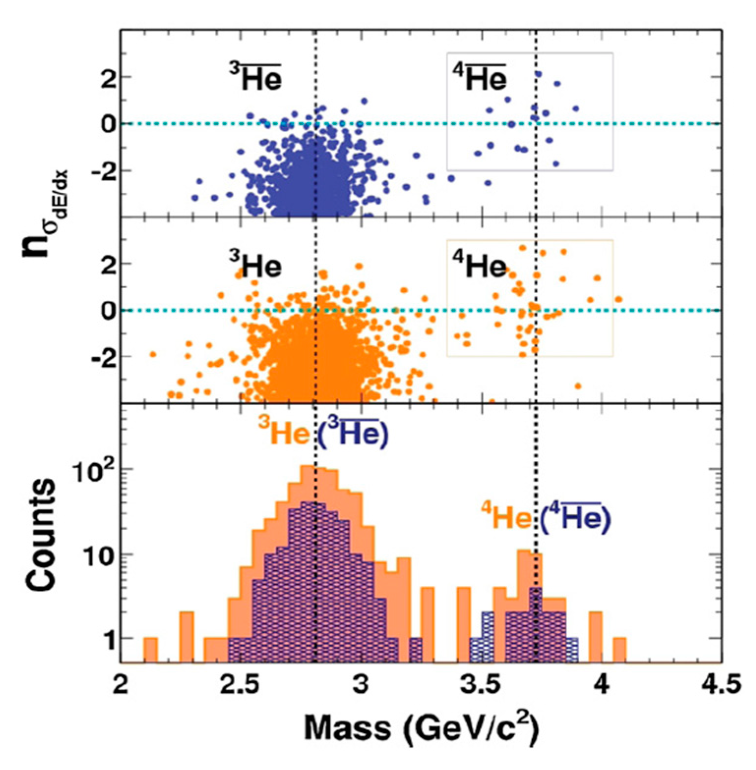
Another example that shows the synergy between dE/dx and the ToF is illustrated with the observation of antimatter Helium-4 [60], as shown in Figure 5. The dE/dx of and 3He/4He versus mass derived from TPC and ToF are demonstrated separately on the top two views. The average masses of 3He () and 4He () are around 2.8 and 3.7 GeV/c2. The bottom view shows statistics about 3He () and 4He (). The mass peaks of 3He and 4He can be separated obviously, which reveals the importance of the ToF system.
3.2. CBM Experiment in GSI
The compressed baryonic matter spectrometer (CBM) [61] is a heavy-ion experiment located at the Facility for Antiproton and Ion Research (FAIR) in Darmstadt, Germany. The goal is to make high-energy nuclei collide and study the quantum chromo-dynamics (QCD) matter under a high baryon densities environment. Towards a high production of particles, the interaction rate of the CBM experiment is intended to 10 MHz for the most demanding probes. Such unprecedented rates require irradiation resistant detectors, high-performance electronics and high-speed computation capability.
3.2.1. The CBM-ToF System
The CBM ToF wall [62,63] is currently under development and construction, and it is designed to be composed of MRPC detectors. To achieve hadron identification of momentum of 4 GeV/c, a system time resolution below 80 ps and efficiency above 95% are required. To match the high-density particle fluxes, the detector’s rate capability is the most challenging issue. These high rate requirements are no longer achievable with MRPCs built in the standard technique with float glass resistive plates. The rate capability [64,65] is limited by the voltage drop of the resistive plates and can be increased by reducing the electrode thickness and resistivity. The efficient way is to look for low resistivity materials for the electrodes to increase the operating current without reducing the voltage applied to the gas.
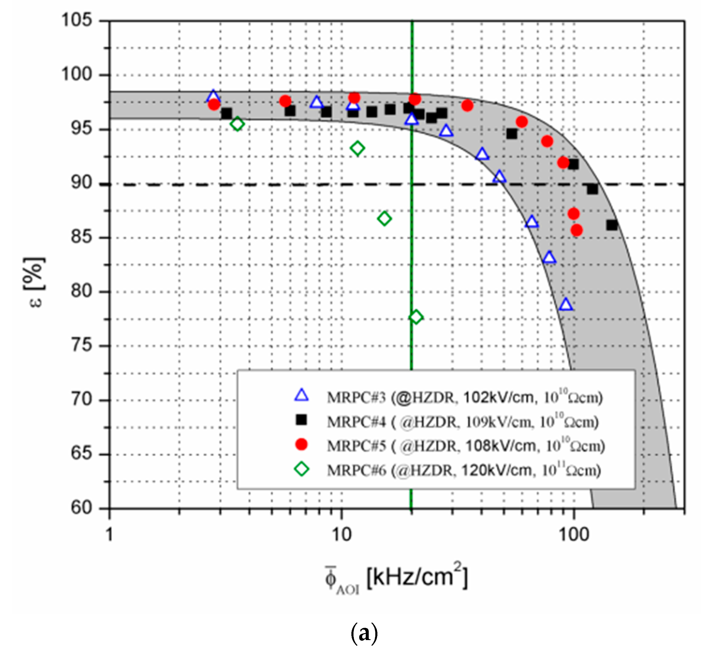
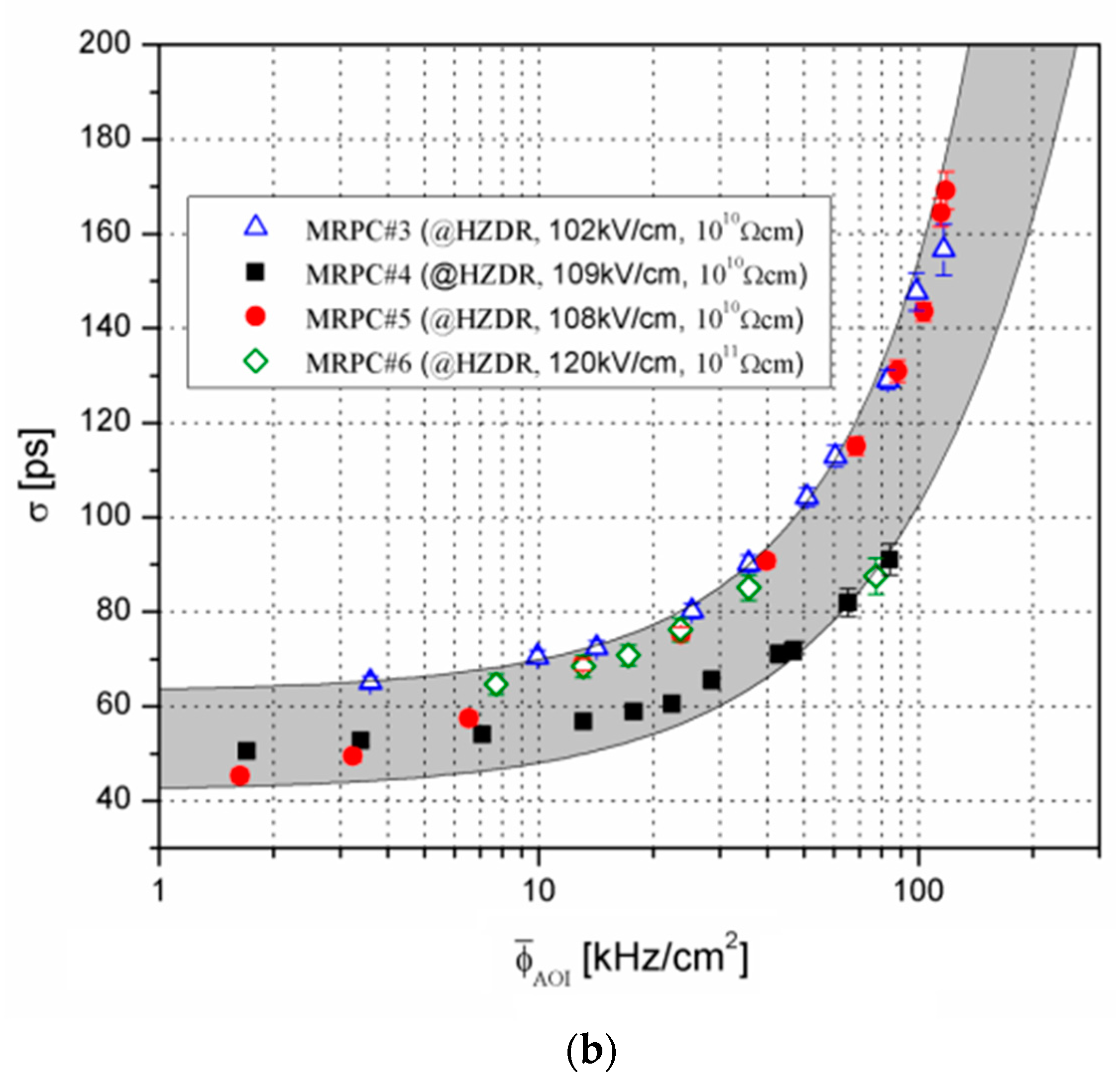
A kind of low resistive glass [66,67] was developed at Tsinghua University. Its main parameters are shown in Table 2. The bulk resistivity is about cm. To meet the requirement of CBM-ToF, around 1000 m2 of low resistive glass is produced. As a result of the fragility of glass, the dimensions of one piece of low resistivity glass is limited to 32 cm × 30 cm. Large area detectors can be achieved by the mosaic MRPC [68]. Similar MRPC prototypes composed of such low resistive glass were validated in a very high rate environment. As shown in Figure 6, at the rate of 70 kHz/cm2, the efficiency above 90% and time resolution around 80 ps [66] are achieved.
The high-performance electronics for the whole CBM ToF wall is based on the PADI [69] and the GET4-ASIC chips [70]. The PADI board has 32 channels, and the threshold can be set via slow control. It can be directly connected to the MRPC readout electrodes inside the gas box, which suppresses the electromagnetically induced noise from outside and matches the impedance from electrodes to the preamplifier itself.
3.2.2. High-Rate MRPC
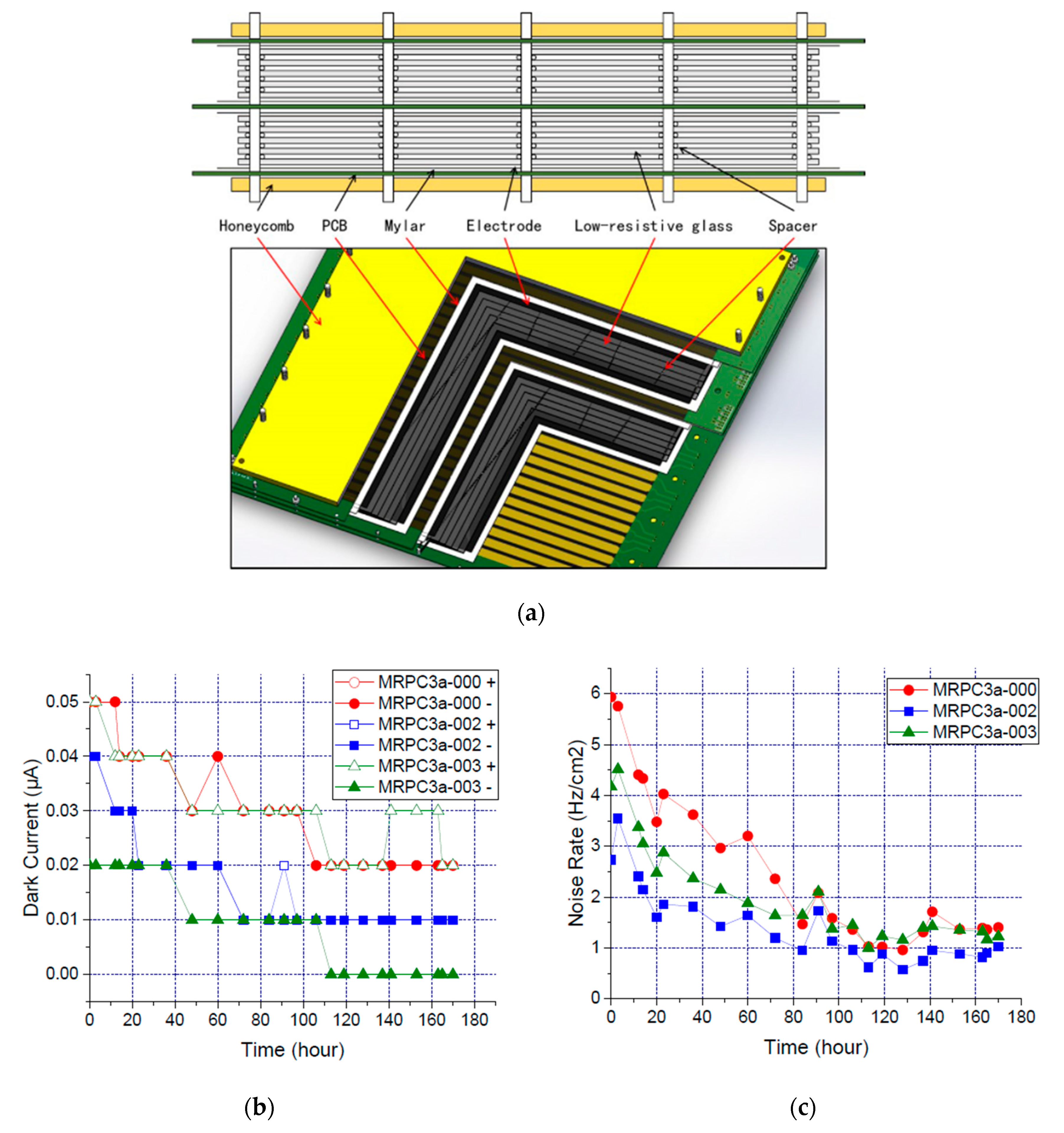
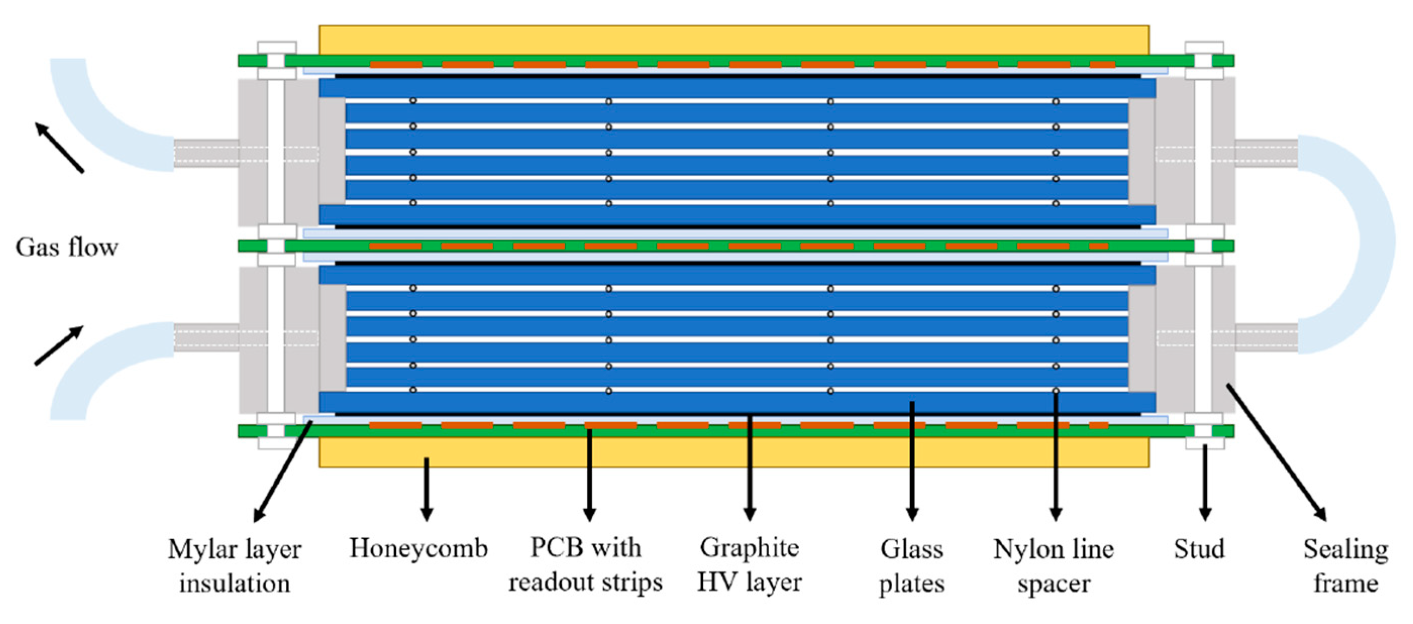
Towards the particle flux ranges from 1–5 kHz/cm2 in the intermediate rate region [63], the double-stack MRPC prototype [26] developed at Tsinghua University has been considered. It is built by the low resistive glass plates described above. This MRPC (Figure 7a) has 2 × 4 gaps with 250 μm gap size and 32 readout strips, each of 1 × 27 cm2. The results of SPS beam time in 2015 for the prototypes were presented in [26]. The efficiency and time resolution curves correspond well to the changes of high voltage and PADI threshold. The efficiency is stable at the working point and maintains above 97% for all the run time. The system time resolution tends to improve with time in the beginning and reaches a value of about 85 ps. The first batch of 73 MRPC detectors [71] has been produced and installed into STAR endcap ToF and mini-CBM ToF.
During the mass production and quality control process, the HV test of MRPC [71] is quite important to ensure its performance. Figure 7b,c shows the monitoring results of the dark current and noise rate after applying the HV. The dark current decreases to around 10 nA with time, and the noise rate finally stays around 1 Hz/cm2. It can be seen that the noise and dark current are quite low when the particle (here is cosmic ray) rate is rather low, which indicates the low noise and good response of the MRPC detector.
3.2.3. Aging Test of a High-Rate MRPC
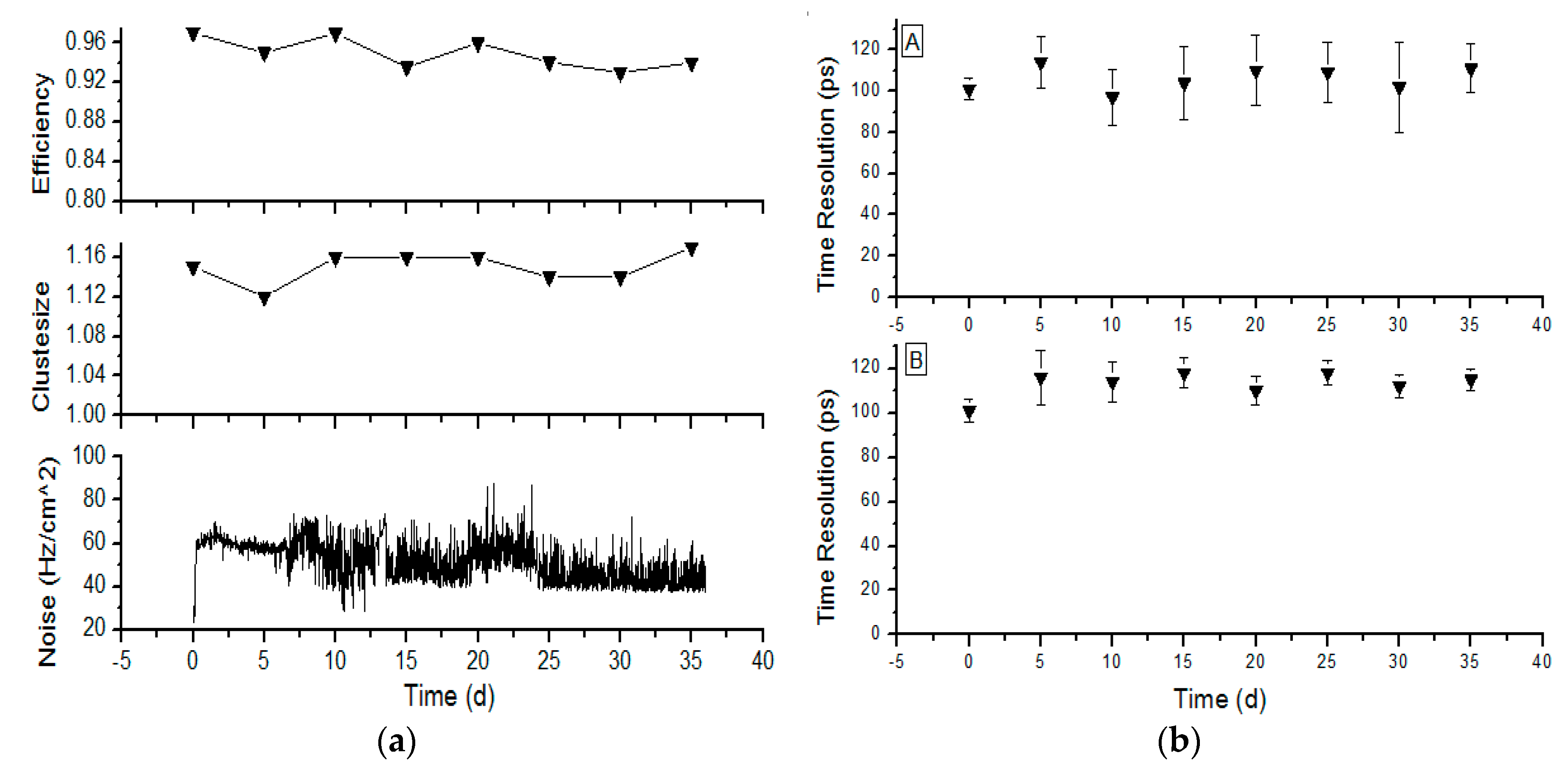
The MRPC based on the new material—the low resistive glass, will operate at high flux and be used in a large experiment for the first time. It is necessary to check its performance stability under a high background environment. For example, an X-ray source can be used to irradiate the detector; at the same time, its performances like efficiency and time resolution can be tested using the cosmic ray, and other performances such as current and counting rate can also be recorded. Figure 8 shows the performance of a high-rate MRPC for a period of 36 days. The integrated charge can reach 0.1 C/cm2 [72], and there is no obvious degradation of the operating performance, which meets the requirements of CBM-ToF.
3.2.4. FAIR Phase 0 Programs
To create an environment where all aspects of the developed detector systems can be verified under real conditions, the FAIR Phase 0 program [73] was carried out. The idea is to install and operate existing FAIR related detector equipment in running experiments all over the world. CBM ToF subsystem participates in two FAIR Phase 0 programs, which will be discussed in the following.
mCBM (mini-CBM) is a scaled-down experiment for CBM located at the SIS18 facility of GSI/FAIR. The primary goal is to validate and optimize the performance of the detector systems, the electronics systems and the online and offline data analysis algorithms in such a high-rate environment. The ToF performance during mCBM beam time in 2019 can be found in [74].
The endcap time-of-flight (eToF) project comprises the installation, commissioning and operation of part of the CBM ToF modules positioned at the STAR apparatus during the Beam Energy Scan II and the participation of data analysis. The eToF upgrade [75] covers the rapidity range from −1.1 to −1.6 for the collider collision mode. For the fixed target collision mode, the PID extension is between 1.6 and 2.1, which is essential to cover the mid-rapidity range.
eToF consists of 36 modules grouped in 12 sectors, and the sectors are arranged in 3 layers in a wheel spokes structure around the beam axis. Each module houses 3 MRPCs, which leads to a total of 108 counter and 6912 readout channels. The full hardware installation was completed in Nov. 2018. After a commissioning phase of about 10 weeks, the first data taking started in February 2019 by recording about 580 M Au + Au events at GeV with an eToF efficiency of 85%. The readout system for eToF uses the free-streaming architecture (no global hardware trigger) and hardware and software components. It comprises 216 PADI (preamplifier and discriminator) and 216 GET4 (TDC) boards (for 108 counters).
3.3. Developments for Future ToF Systems
3.3.1. High Rate and Ultrahigh Time Resolution MRPC
Although the science of the electromagnetic force between the atomic nucleus and the electrons is well understood, we still know little about the nucleon’s structure and the quarks and gluons that compose the nuclei. The future experiments with higher luminosity and beam energy, such as the 12 GeV program of JLab [76,77] and the electron-ion collider (EIC) [78] at Brookhaven Lab, will provide a powerful tool and simultaneously impose strict requirements on the detector devices.
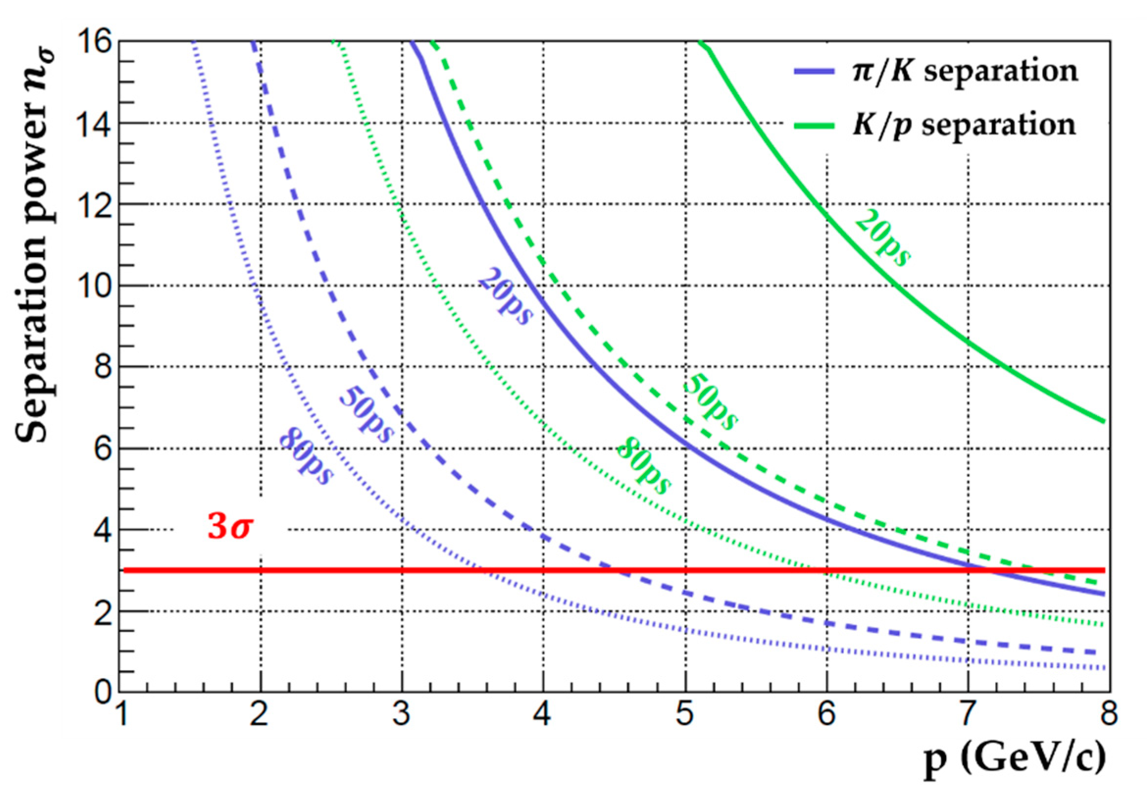
For the SoLID experiment [79,80] at JLab, the particle separation for different ToF time resolutions and for the 8 m flight distance can be calculated according to Equation (4), as shown in Figure 10. A ToF with a time resolution of 20 ps and a rate capability of 10 kHz/cm2 is required to achieve K/π separation at the momentum range of 1–7 GeV/c. For hadron identification in the future EIC detector, the Cherenkov detector is thought to be the only possibility of covering the high momentum range (5–50 GeV/c, depending on the polar angle), while ToF or 𝑑𝐸/𝑑𝑥 (like a TPC) system is needed to cover the low momentum range (up to a few GeV/c) [81]. At the typical distance of 4 m available on the hadron-going side, a 10 ps ToF would provide π/K separation up to 7 GeV/c.
Several R&D projects currently have been putting effort into investigating high-performance detectors. M.C.S. Williams et al. [82] from the LHC-ALICE group developed a 24 gap MRPC with a gap width of 160 μm. It was arranged into 4 stacks, each with 6 gaps. The 400 μm thick float glass plates were employed as the resistive plates. Using the NINO electronics and the oscilloscope-based system, a time resolution of 27 ps for cosmic ray test and 21 ps for beam test has been obtained. Z. Liu et al. [83,84] has built and carefully studied three kinds of 20-gap MRPCs with very thin (0.28 mm) float glass plates and different gap sizes of 160 μm, 140 μm and 120 μm. They are able to reach an efficiency of 90% at a flux rate of around 20 kHz/cm2, while the 140 μm-MRPC gives the best time resolution of 25 ps. In order to further improve the rate capability, they built a 10-gap MRPC [85] with the low-resistivity glass from Picotech SAS. During the beam test at ELBE, this MRPC always keeps the efficiency above 95%. The time resolutions of 36 ps and 50 ps are obtained at the rate of 2 kHz/cm2 and 100 kHz/cm2, respectively.
Tsinghua University and USTC [79] have been putting much effort into carrying out R&D of the required detector for SoLID-ToF. Just like the CBM-ToF, the low resistive silicate glass is employed as the resistive plate to achieve a high rate capability. To better understand the detector’s working principles and improve the performance, a standalone simulation framework of the MRPC detector has been built and carried out [86,87]. The energy deposition produced by the passing particles is simulated based on the PAI model [88], which is proved to be effective for very thin absorbers. The ionized electrons drifting in the gas gap will start the avalanche following the Townsend effect [33] under the applied electric field as soon as they are created and generate an induced signal on the pick-up electrodes according to Ramo theory [39]. The frontend electronics (FEE) response and noise can be included to study the detector performance under different experimental setups. By analyzing the simulation data and full signal information, the performance of detectors with different structures at various working conditions can be easily studied.
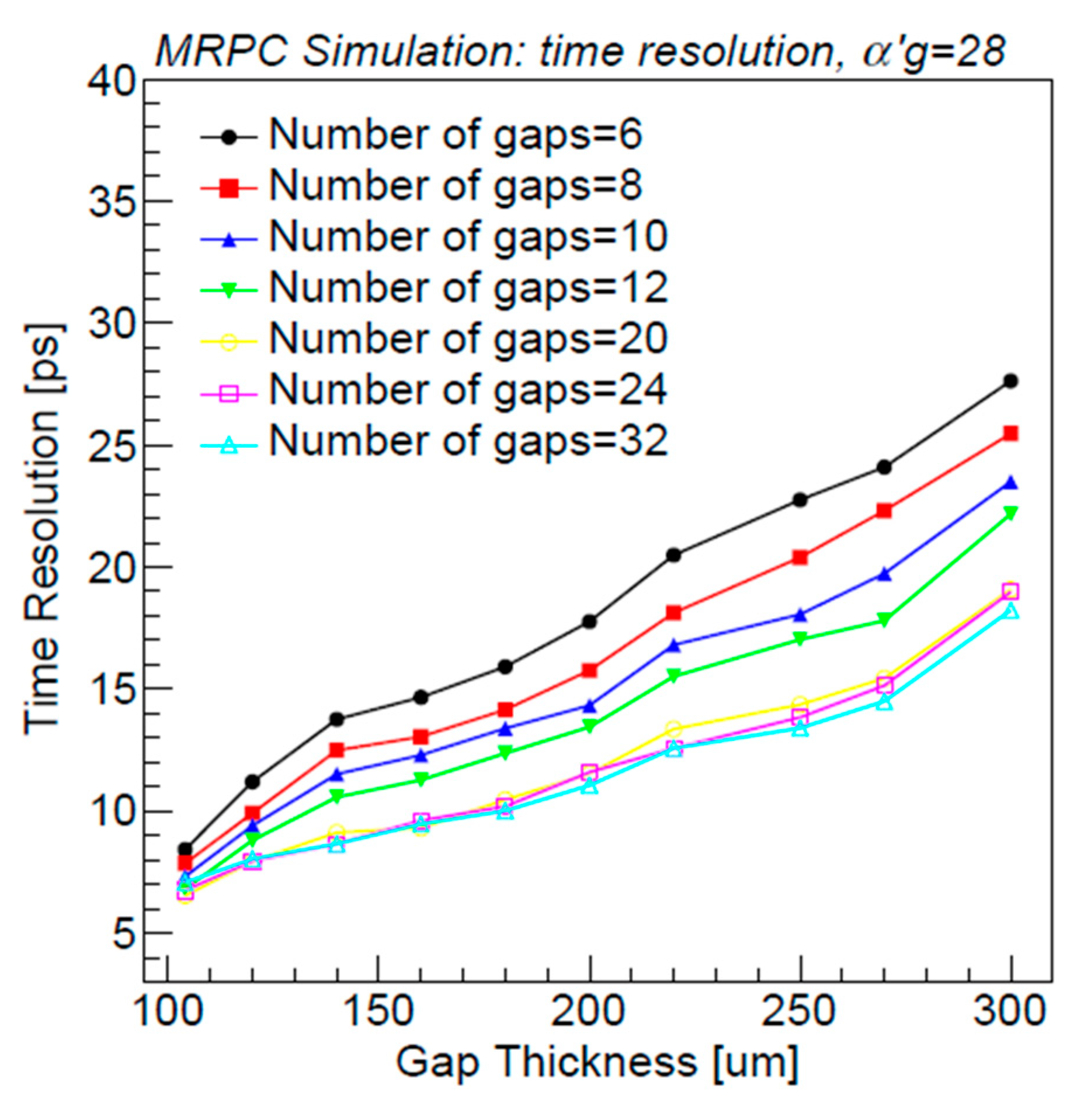
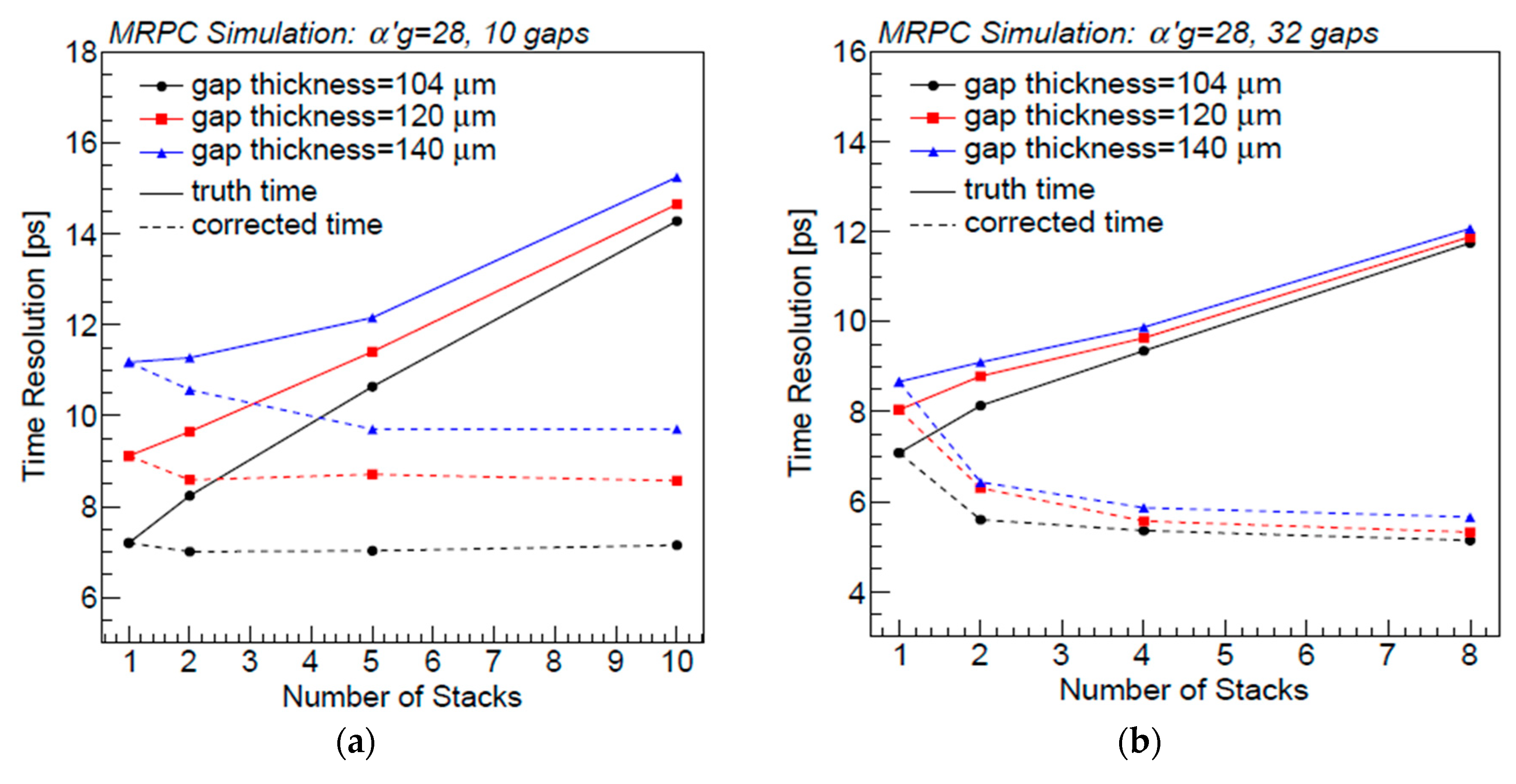
Figure 11 [89] shows the relations of intrinsic time resolution and MRPC structural parameters. It is evident that reducing gap thickness and adding more gaps can achieve a better time resolution. Moreover, to reach the goal of 20 ps time resolution, the possible choices for future MRPCs are mainly the designs with thickness below 160 μm and at least 20 gas gaps, which ensures the detector resolution better than 10 ps. In general, gaps in this kind of MRPCs are arranged into several stacks so that the applied working voltage can be limited to a reasonable level. Figure 12 [89] shows the time resolution changes associated with the number of stacks in a detector. We can see that when fixing the total number of gaps and dividing them into more stacks, the time resolution becomes larger. It is because more stacks mean a much thicker chamber and a longer distance between the very first and last gaps, which will lead to a larger shift of the avalanche time.
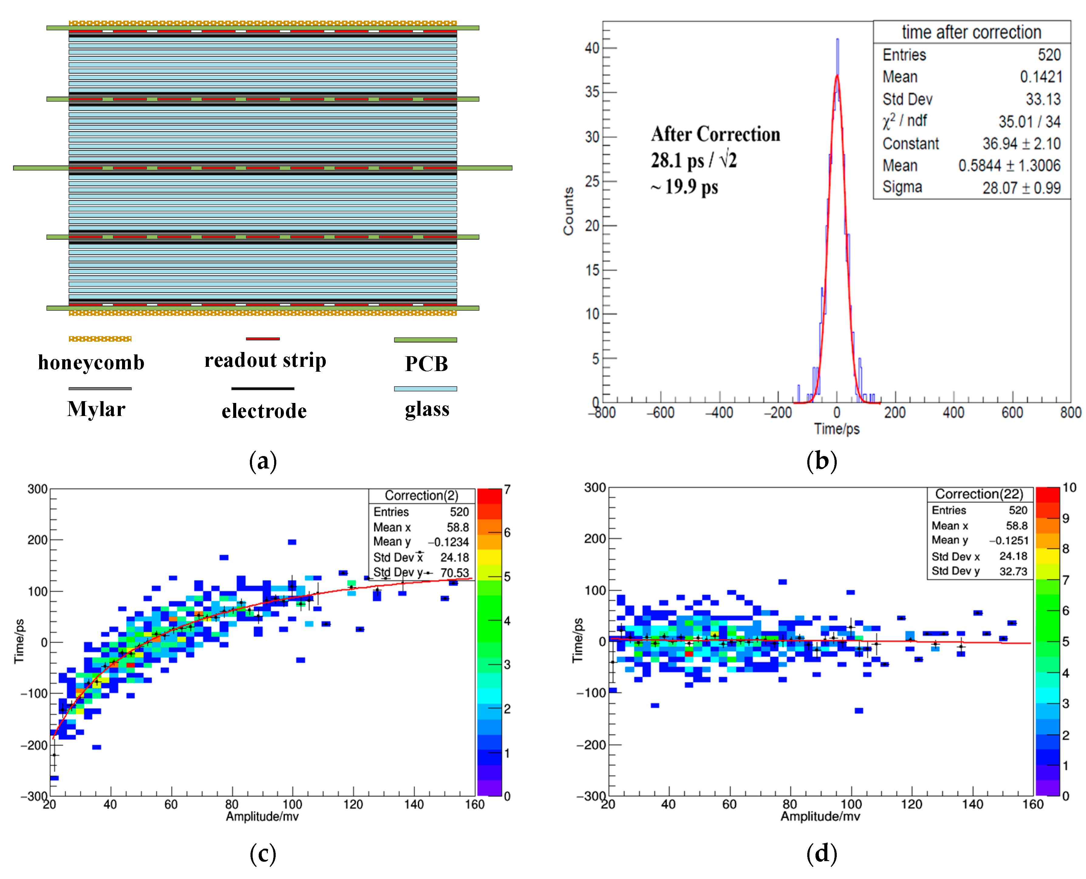
Based on the Monte Carlo simulation and the above study, a 32-gap MRPC detector [90] was developed. As depicted in Figure 13a, the MRPC is arranged into four stacks, each stack with eight gaps. The thickness of each gap is only 104 μm. 6 readout strips with 1 cm pitch are configured on the PCB sheets. Five PCBs are required in this design. The cathode and anode signals are transmitted through differential cables. During the preliminary cosmic ray test, the high-performance analog frontend electronics (AFE) [91] from USTC and the Lecroy oscilloscope were used. The crossing time of a signal is determined when setting a fixed threshold, and it is related to the amplitude of the signal. Thus, the time-slewing correction should be carried out, and a general formula is given below
where is the crossing time of a signal and q represents the signal amplitude or charge, to are the undetermined coefficients that can be obtained by fitting the relations, as depicted in Figure 13c,d.
After the slewing correction, the time distribution is shown in Figure 13b, and a time resolution of 19.9 ps has been achieved at the electric field of 150 kV/cm. Now they are working on the new MRPCs with low resistive glass to reach both high time resolution and high rate.
3.3.2. The New Time Reconstruction Algorithm
In recent years, artificial neural networks (ANNs) have become a powerful and popular machine learning (ML) method in many fields, including high energy physics analysis [92,93,94,95]. As mentioned before, the ToT of an MRPC signal is usually discriminated against and digitized by TDC. The main drawback is that the time jitter of each TDC channel is typically 20 ps, which is a big issue to achieve a system resolution better than 20 ps. Moreover, the threshold crossing time is related to the pulse amplitude, so the time-slewing effect should be carefully corrected. Wang et al. [96] proposed neural network (NN) algorithms to reconstruct the MRPC time. The Monte Carlo simulation described before provided labeled training datasets to train the network model, while the experiment datasets are used to test. The FC (fully connected) and long short-term memory network (LSTM) are detailed studied [96]. Moreover, they both give more accurate and precise time resolution results compared to the ToT method.
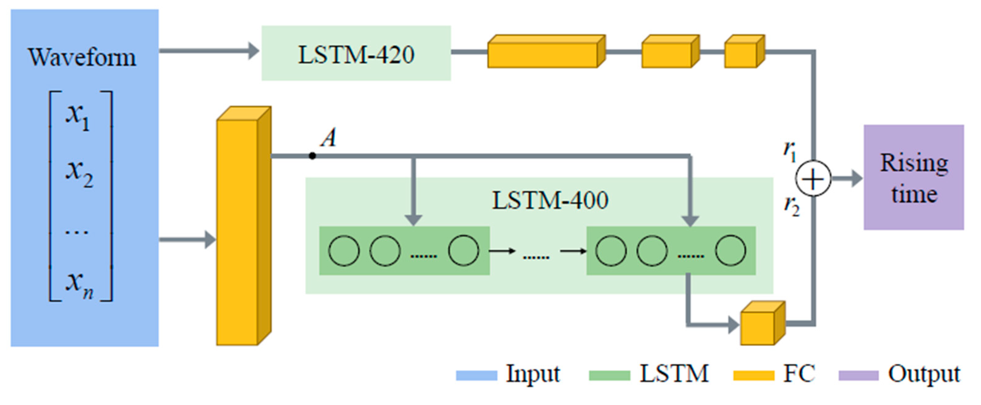
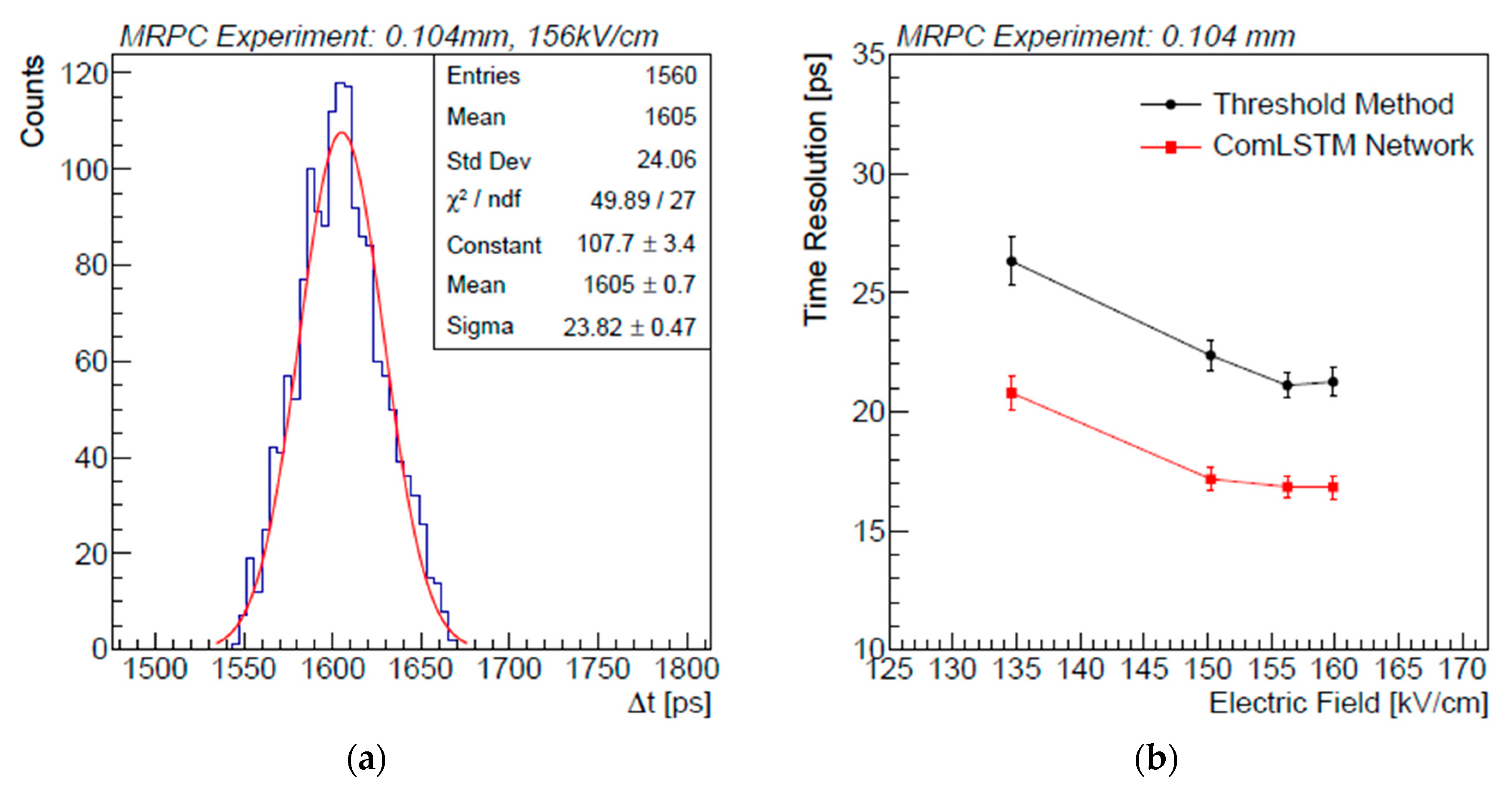
F. Wang also proposed a combined LSTM (ComLSTM) neural network (see Figure 14), which combines the advantages of both the LSTM and FC. The detailed description of the ComLSTM structure can be found in [97]. For the 32-gap MRPC, same as [90], timing performances with both the ComLSTM neural network and the traditional threshold-based method are shown in Figure 15. The best time resolution with the ComLSTM can reach ps, which is better than that of the ToT method. Although the neural networks have shown better performance, many efforts need to be put into implementing and validating them in high-energy physics and particle experiments.
3.3.3. Gas Related Studies
The choice of the working gas mixture for MRPCs has always been an important topic. It should allow the MRPC detector to perform successfully and stably for different purposes, and however, be eco-friendly. This indicates that the gas mixture should have a low ozone depletion power (ODP) and global warming potential (GWP). The tetrafluoroethane currently used in MRPCs is ozone friendly but with a GWP of about 1430 (the reference GWP of CO2 is 1). Therefore, much research has gone into looking for possible replacements. Among the possibilities, HFO-1234ze [98,99] with a GWP of 6 is one of the most popular candidates, and tests of gas mixtures based on it are ongoing.
Another reasonable approach is to reduce gas consumption or recycle gas. The CSR external target experiment (CEE) in Lanzhou, China, will adopt a sealed technology of MRPC to construct the ToF system. The MRPC detector [100], shown in Figure 16, is sealed by gluing an integral 3D-printed frame and the outermost electrodes together. It can operate stably with a gas flux of 4 mL/min, which is extremely low compared to that when MRPCs are placed in a sealed box.
3.4. A Brief Summary
The main properties of the MRPC detectors used in large experiments are summarized in Table 3. The efficiency of all these MRPCs is very close to 100%, which is quite good. MRPCs with a gap thickness of around 0.25 mm can reach a time resolution of 60 ps, while much thinner gaps and a higher working field can lead to a time resolution better than 20 ps. The rate capability of MRPCs made of the float glass sheet is typically below 1 kHz/cm2. MRPCs based on the low resistive glass ( cm), which can reach a rate of up to 70 kHz/cm2, are considered by CBM and future experiments.
The main solution for the present readout electronics is a combination of amplifier and TDC, shown in Table 4. Their overall time jitters are usually around 20 ps. The ToT method is regularly used to acquire the arriving time of a signal, and the time–amplitude effect should be corrected. For future experiments such as SoLID and EIC, to achieve ultra-high time resolution, an MRPC detector with many thin gaps and the signal sampling technology are proposed. Thanks to the full signal sampling techniques, neural networks can be used to reconstruct the detector time.
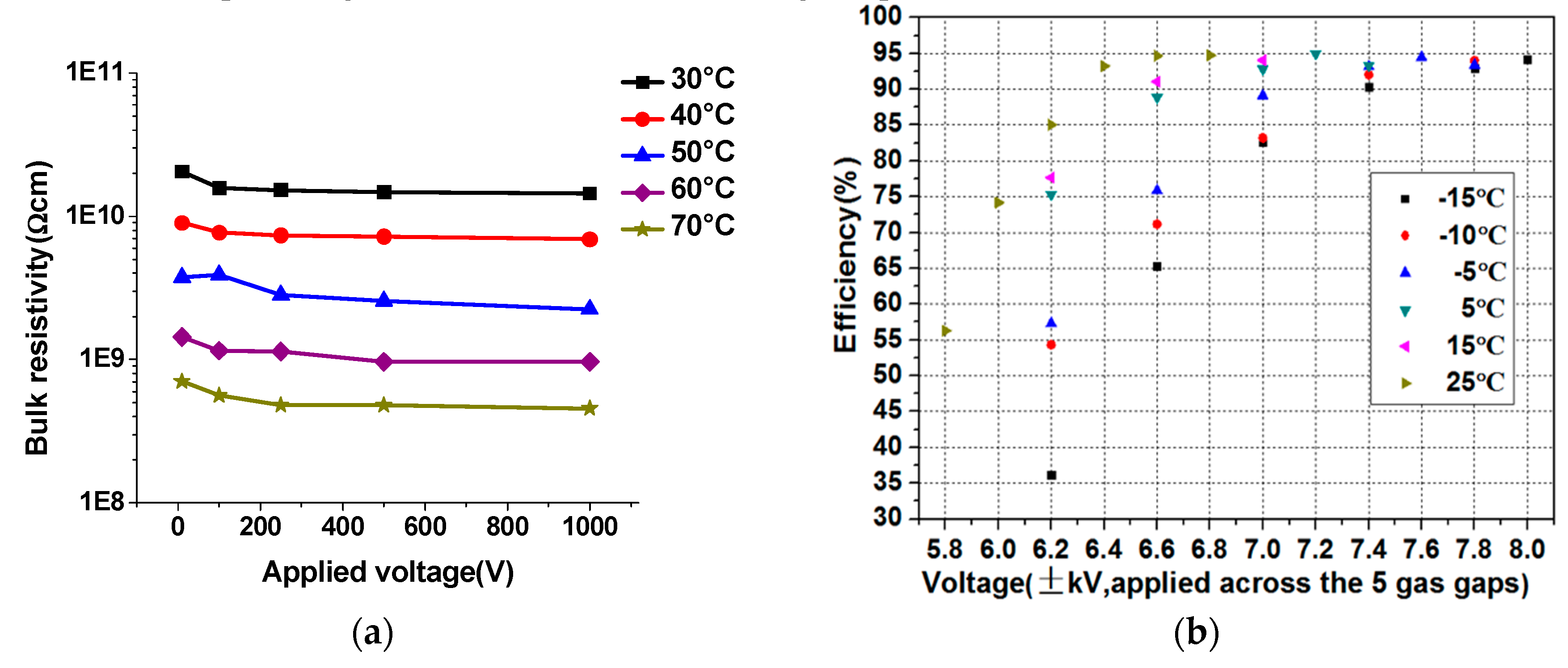
When you start digging into the operation of MRPC detectors, there are many important issues that should be well noticed and investigated. The working point varies for MRPCs with different structures and working conditions. For example, the wide-gap (~0.25 mm) MRPC in avalanche mode usually operates at the electric field of around 110 kV/cm, while the very thin-gap (~0.1 mm) MRPC can work well at 150 kV/cm to achieve a good resolution; the working point will shift significantly for different gas mixtures [101,102,103,104,105]; MRPCs built with different resistive materials may have different working voltage and efficiency plateau: we can see from ref. [102] that the 6-gap MRPC with low-resistivity glass reaches the plateau at the electric field of around 110 kV/cm and the normal 6-gap MRPC reaches its plateau at a higher electric field of 120 kV/cm. In addition, temperature and pressure have a significant influence on the operation and performance of MRPC detectors. On one hand, the temperature will affect the resistivity of the electrode and hence influence the resistor-–capacitance circuit and the current of the detector [106]. The resistivity generally decreases by order of magnitude for a temperature increase of about 20 °C both for Bakelite and float glass, as shown in Figure 17a, and it has a direct effect on the chamber’s rate capability [107,108]. On the other hand, the gas parameters (such as drift velocity and Townsend coefficient) are determined by the gas mixtures and their working electric field E, temperature T and pressure P. If the environmental conditions change, the working voltage of the MRPC detector needs to be adjusted to keep MRPC performance stable. This is essential in the operation of large experiments. Thus, the idea of “effective voltage” is given to describe the relationship
where is the applied high voltage, T and P are the actual temperature and pressure, and are the reference values. The efficiency versus the high voltage at different temperatures [109] is reported in Figure 17b. The working voltage varies at different temperatures. For every 5 °C increase of temperature, the working points should be decreased by 200 V. If not, the overvoltage will cause big sparks and streamers. Therefore, one must carefully take the environmental conditions into account when operating the MRPC detectors in large experiments.
4. Conclusions and Outlook
In summary, the MRPC detector is currently a standard technology for the time of flight system. This paper has reviewed its famous applications on the ToF system in several experiments. The performances, including the time resolution and particle identification, were described in detail. Several important issues, such as the gas mixtures, the applied high voltage and the effects of temperature and pressure, are elaborated during the operation of the MRPC detector. The paper has also discussed some recent advances and outlooks for the future development of the next generation MRPC.
However, there are still some new requirements and unclear problems that need to be explored further.
- At present, unfriendly gases with high GWP are used. A big research effort must be continually put into studying the eco gas mixtures for MRPC to work stably in different conditions;
- High rate and high space–time resolution MRPCs with integration and reliability would have considerable potential for development and future applications.
Author Contributions
Y.W. and Y.Y. conceived the idea; Y.Y. wrote and edited the paper; Y.W. revised the paper. All authors have read and agreed to the published version of the manuscript.
Funding
This research was funded by the National Natural Science Foundation of China under Grant No. U1832118, 11927901, 11420101004, 11461141011, 11275108, and 11735009. This research was also funded by the Ministry of Science and Technology under Grant No. 2018YFE0205203, 2015CB856905, 2016 YFA0400100.
Conflicts of Interest
The authors declare no conflict of interest.
References
- Lippmann, C. Particle identification. Nucl. Instrum. Methods A 2012, 666, 148–172. [Google Scholar] [CrossRef] [Green Version]
- Akimov, V.A.; Akindinov, V.A.; Boyarinov, S.V.; Voloshin, K.G.; Vorobyev, L.S.; Grishuk, Y.G.; Zagreev, B.V.; Kats, M.M.; Kiselev, S.M.; Martemiyanov, A.N.; et al. A parallel-plate chamber as a detector for time-of-flight measurements. Instrum. Exp. Tech. 2002, 45, 493–500. [Google Scholar] [CrossRef]
- Akimov, V.A.; Akindinov, V.A.; Boyarinov, S.V.; Voloshin, K.G.; Vorobyev, L.S.; Grishuk, Y.G.; Zagreev, B.V.; Kats, M.M.; Kiselev, S.M.; Martemiyanov, A.N.; et al. Studying the characteristics and optimizing the parameters of a parallel-plate chamber used as a detector for time-of-flight measurements. Instrum. Exp. Tech. 2004, 47, 589–597. [Google Scholar] [CrossRef]
- Rizzo, A.; Narici, L.; Messi, R.; Cipollone, P.; De Donato, C.; Di Fino, L.; Iannlli, M.; La Tessa, C.; Manea, C.; Masciantoni, G. A compact time-of-flight detector for space applications: The LIDAL system. Nucl. Instrum. Methods A 2018, 898, 98–104. [Google Scholar] [CrossRef]
- Zhao, J.W.; Sun, B.H.; Tanihata, I.; Terashima, S.; Zhu, L.H.; Enomoto, A.; Nagae, D.; Nishimura, T.; Omika, S.; Ozawa, A. Reaching time resolution of less than 10 ps with plastic scintillation detectors. Nucl. Instrum. Methods A 2016, 823, 41–46. [Google Scholar] [CrossRef] [Green Version]
- Cumalat, J.P.; Cheung, H.W.K.; Hassed, J.; Smith, B.D. Effects of magnetic fields on the light yield of scintillators. Nucl. Instrum. Methods A 1990, 293, 606–614. [Google Scholar] [CrossRef]
- Buzhan, P.; Dolgoshein, B.; Filatov, L.; Ilyin, A.; Kantzerov, V.; Kaplin, V.; Karakash, A.; Kayumov, F.; Klemin, S.; Popova, E.; et al. Silicon photomultiplier and its possible applications. Nucl. Instrum. Methods A 2003, 504, 48–52. [Google Scholar] [CrossRef]
- Herbert, D.J.; Saveliev, V.; Blecari, N.; D’Ascenzo, A.; Golovin, A. First results of scintillator readout with silicon photomultiplier. IEEE Trans. Nucl. Sci. 2006, 53, 389–394. [Google Scholar] [CrossRef] [Green Version]
- Carnesecchi, F.; Agrawal, N.; Alici, A.; Antonioli, P.; Arcelli, S.; Basile, M.; Bellini, F.; Cavazza, D.; Cifarelli, L.; Cindolo, F. Experimental study of the time resolution of SiPM coupled to scintillator. Nucl. Instrum. Methods A 2020, 982, 164484. [Google Scholar] [CrossRef]
- Alicia, A.; Antonioli, P.; Arcelli, S.; Basile, M.; Belline, F.; Carnessechi, F.; Cavaza, D.; Cifarelli, L.; Cindolo, F.; Colacci, M. Time resolution measurements with SiPMs coupled to a scintillator. J. Instrum. 2018, 14, P09012. [Google Scholar] [CrossRef] [Green Version]
- Apollinari, G.; Alonso, B.; Bruning, O.; Lamont, M.; Rossi, L. High-luminosity large hadron collider (HL-LHC): Preliminary design report. Tech. Rep. 2015. [Google Scholar] [CrossRef]
- Vinke, R.; Löhner, H.; Schaart, D.R.; van Dam, H.T.; Seifert, S.; Beekman, F.J.; Dendooven, P. Optimizing the timing resolution of SiPM sensors for use in TOF-PET detectors. Nucl. Instrum. Methods A 2009, 610, 188–191. [Google Scholar] [CrossRef]
- Powolny, F.; Auffray, E.; Brunner, S.E.; Goettlich, M.; Hillemans, H.; Jarron, P.; Lecoq, P.; Meyer, T.; Shultz, H.C. Time-based readout of a silicon photomultiplier (SiPM) for time of flight positron emission tomography (TOF-PET). IEEE Trans. Nuc. Sci. 2011, 58, 597–604. [Google Scholar] [CrossRef] [Green Version]
- Pellegrini, G.; Fernández-Martínez, P.; Baselga, M.; Fleta, C.; Flores, D.; Greco, V.; Hidalgo, S.; Mandic, I.; Krambergs, G.; Quiron, D. Technology developments and first measurements of low gain avalanche detectors (LGAD) for high energy physics applications. Nucl. Instrum. Methods A 2014, 765, 12–16. [Google Scholar] [CrossRef]
- Yang, X.; Alderweireldt, S.; Atanov, N.; Ayoub, M.K.; da Costa, J.; García, L.C.; Chen, H.; Christie, S.; Cindro, V.; Cui, H.; et al. Layout and performance of HPK prototype LGAD sensors for the high-granularity timing detector. Nucl. Instrum. Methods A 2020, 980, 164379. [Google Scholar] [CrossRef]
- Cartigliaa, N.; Staiano, A.; Vola, S.; Arcidiacono, R.; Cirio, R.; Cenna, F.; Ferreo, M.; Monaco, V.; Mulargia, R.; Obertino, M. Beam test results of a 16 ps timing system based on ultra-fast silicon detectors. Nucl. Instrum. Methods A 2017, 850, 83–88. [Google Scholar] [CrossRef]
- Breton, D.; Delagnes, E.; Maalami, J.; Nishimura, K.; Ruckman, L.L.; Varner, G.; Vavra, J. High resolution photon timing with MCP-PMTs: A comparison of a commercial constant fraction discriminator (CFD) with the ASIC-based waveform digitizers TARGET and WaveCatcher. Nucl. Instrum. Methods A 2011, 629, 123–132. [Google Scholar] [CrossRef] [Green Version]
- Barnyakov, A.Y.; Barnyakov, M.Y.; Blinov, M.E.; Bobrovnikov, V.S.; Bykov, A.V.; Ivanov, V.Y.; Katchin, A.A.; Mamoshina, E.V.; Ovtin, I.V.; Petrukhin, K.G. Development of a picosecond MCP based particle detector. Nucl. Instrum. Methods A 2020, 952, 161831. [Google Scholar] [CrossRef]
- Va’vra, J. PID techniques: Alternatives to RICH methods. Nucl. Instrum. Methods A 2017, 876, 185–193. [Google Scholar] [CrossRef] [Green Version]
- Sykora, T. ATLAS Collaboration. ATLAS Forward Proton Time-of-Flight Detector: LHC Run2 performance and experiences. J. Instrum. 2020, 15, C10004. [Google Scholar] [CrossRef]
- Wang, X.Z.; Sun, Y.J.; Li, C.; Heng, Y.K.; Wu, Z.; Cao, P.; Dai, H.L.; Ji, X.L.; Gong, W.X.; Liu, Z. The upgrade system of BESIII ETOF with MRPC technology. J. Instrum. 2016, 11, C08009. [Google Scholar] [CrossRef] [Green Version]
- Akindinov, A.; Alici, A.; Antonioli, P.; Arcelli, S.; Baek, Y.W.; Basile, M.; Cara Romeo, G.; Cifarelli, L.; Cindolo, F.; De Caro, A.; et al. Final test of the MRPC production for the ALICE TOF detector. Nucl. Instrum. Methods A 2009, 602, 709–712. [Google Scholar] [CrossRef]
- Akindinov, A.; Alici, A.; Antonioli, P.; Arcelli, S.; Basille, M.; Bellini, F.; Caffari, D.; Cara Romeo, G.; Ciffarlli, L.; Cindolo, F.; et al. The MRPC-based ALICE time-of-flight detector: Commissioning and first performance. Nucl. Instrum. Methods A 2012, 661, S98–S101. [Google Scholar] [CrossRef]
- Carnesecchi, F. Performance of the ALICE time-of-flight detector at the LHC. J. Instrum. 2019, 14, C06023. [Google Scholar] [CrossRef] [Green Version]
- Deppner, I.; Herrmann, N.; Akindinov, A.; Bartos, D.; Balaceanu, A.; Belugorov, S.; Cao, P. The CBM Time-of-Flight wall—A conceptual design. J. Instrum. 2014, 9, C10014. [Google Scholar] [CrossRef]
- Wang, Y.; Lyu, P.; Huang, X.; Han, D.; Xie, B.; Li, Y.; Herrmann, N.; Deppner, I.; Simon, C.; Loizeau, P.A. Development and test o f a real-size MRPC for CBM-TOF. J. Instrum. 2016, 11, C08007. [Google Scholar] [CrossRef] [Green Version]
- Bonner, B.; Eppley, G.; Lamas-Valverde, J.; Llope, W.J.; Nussbaum, T.; Platner, E.; Roberts, J.; Cerron, E. A multigap resistive plate chamber prototype for time-of-flight for the STAR experiment at RHIC. Nucl. Instrum. Methods A 2002, 478, 176–179. [Google Scholar] [CrossRef]
- Bonner, B.; Chen, H.; Geurts, F.; Lamas-Valverde, J.; Li, C.; Llope, W.J.; Nussmaum, T.; Platner, E.; Roberts, J. A single time-of-flight tray based on multigap resistive plate chambers for the STAR experiment at RHIC. Nucl. Instrum. Methods A 2003, 508, 181–184. [Google Scholar] [CrossRef]
- Wang, Y.; Wang, J.B.; Cheng, J.; Li, Y.; Chen, H.; Li, J. Production and quality control of star-tof MRPC. Nucl. Instrum. Methods A 2010, 613, 200–206. [Google Scholar] [CrossRef]
- Park, S. Production of RPC gaps for the PHENIX upgrade. Nucl. Instrum. Methods A 2012, 661, S82–S85. [Google Scholar] [CrossRef]
- Santonico, R.; Cardarelli, R. Development of resistive plate counters. Nucl. Instrum. Methods A 1981, 187, 377–380. [Google Scholar] [CrossRef]
- Riegler, W.; Lippmann, C.; Veenhof, R. Detector physics and simulation of resistive plate chambers. Nucl. Instrum. Methods A 2003, 500, 144–162. [Google Scholar] [CrossRef] [Green Version]
- Cerron Zeballos, E.; Crotty, I.; Hatzifotidau, D.; Lamas Valverde, J.; Neupane, S.; Williams, M.C.S.; Zichichi, A. A new type of resistive plate chamber: The multigap RPC. Nucl. Instrum. Methods A 1996, 374, 132–136. [Google Scholar] [CrossRef] [Green Version]
- Townsend, J.S. The conductivity produced in gases by the motion of negatively-charged ions. Nature 1900, 62, 340–341. [Google Scholar] [CrossRef] [Green Version]
- Lippmann, C.; Riegler, W. Space charge effects in resistive plate chambers. Nucl. Instrum. Methods A 2004, 517, 54–76. [Google Scholar] [CrossRef] [Green Version]
- Fonte, P. Survey of physical modelling in resistive plate chambers. J. Instrum. 2013, 8, P08007. [Google Scholar] [CrossRef] [Green Version]
- Lippmann, C.; Riegler, W. Detailed RPC avalanche simulations. Nucl. Instrum. Methods A 2004, 533, 11–15. [Google Scholar] [CrossRef] [Green Version]
- Abbrescia, M.; Colaleo, A. Progresses in the simulation of resistive plate chambers in avalanche mode. Nucl. Phys. B Proc. Suppl. 1999, 78, 459–464. [Google Scholar] [CrossRef] [Green Version]
- Riegler, W. Induced signals in resistive plate chambers. Nucl. Instrum. Methods A 2002, 491, 258–271. [Google Scholar] [CrossRef] [Green Version]
- Ramo, S. Currents induced by electron motion. Proc. IRE 1939, 27, 584–585. [Google Scholar] [CrossRef]
- Riegler, W. Extended theorems for signal induction in particle detectors VCI 2004. Nucl. Instrum. Methods A 2004, 535, 287–293. [Google Scholar] [CrossRef]
- Riegler, W.; Burgarth, D. Signal propagation, termination, crosstalk and losses in resistive plate chambers. Nucl. Instrum. Methods A 2002, 481, 130–143. [Google Scholar] [CrossRef] [Green Version]
- Fonte, P. Frequency-domain formulation of signal propagation in multistrip resistive plate chambers and its low-loss, weak-coupling analytical approximation. J. Instrum. 2019, 14, C09020. [Google Scholar] [CrossRef] [Green Version]
- Gonzalez-Diaz, D.; Chen, H.; Wang, Y. Signal coupling and signal integrity in multi-strip resistive plate chambers used for timing applications. Nucl. Instrum. Methods A 2011, 648, 52–72. [Google Scholar] [CrossRef] [Green Version]
- Yu, Y.; Wang, Y.; Han, D.; Chen, X.; Lyu, P.; Wang, F.; Li, Y. Simulation and measurement of the impedance of transmission lines in MRPC detector. J. Instrum. 2019, 14, T11006. [Google Scholar] [CrossRef]
- Yu, Y.; Wang, Y.; Han, D.; Chen, X.; Lyu, P.; Wang, F. Study of transmission-line impedance of strip lines in an MRPC detector. Nucl. Instrum. Methods A 2020, 953, 163152. [Google Scholar] [CrossRef]
- Harrison, M.; Ludlam, T.; Ozaki, S. RHIC project overview. Nucl. Instrum. Methods A 2003, 499, 235–244. [Google Scholar] [CrossRef] [Green Version]
- STAR Collaboration. The STAR experiment at the relativistic heavy ion collider. Nuc. Phys. A 1994, 566, 277c–286c. [Google Scholar] [CrossRef] [Green Version]
- The STAR TOF Collaboration. Proposal for a Large Area Time of Flight System for STAR. Available online: https://www.star.bnl.gov/public/tof/publications/TOF_20040524.pdf (accessed on 1 July 2020).
- Anghinolfi, F.; Jarron, P.; Krummenacher, F.; Usenko, E.; Williams, M.S.C. NINO: An ultrafast low-power front-end amplifier discriminator for the time-of-flight detector in the ALICE experiment. IEEE Trans. Nucl. Sci. 2005, 51, 1974–1978. [Google Scholar] [CrossRef] [Green Version]
- Anghinolfi, F.; Jarron, P.; Martemiyanov, A.N.; Usenko, E.; Wenniger, H.; Williams, M.C.S.; Zichichi, A. NINO: An ultra-fast and low-power front-end amplifier/discriminator ASIC designed for the multigap resistive plate chamber. Nucl. Instrum. Methods A 2004, 533, 183–187. [Google Scholar] [CrossRef]
- Christiansen, J. High Performance Time to Digital Converter Manual. Available online: https://tdc.web.cern.ch/TDC/hptdc/docs/hptdc_manual_ver2.2.pdf (accessed on 1 July 2020).
- Mota, M.; Christiansen, J.; Debieux, S.; Ryjov, V.; Moreira, P.; Marchioro, A. A flexible multichannel high-resolution time-to-digital converter ASIC. In Proceedings of the 2000 IEEE Nuclear Science Symposium Conference Record, Lyon, France, 15–20 October 2000; Volume 2, pp. 9/155–9/159. [Google Scholar] [CrossRef]
- Schambach, J.; Hoffmann, G.; Eppley, G.; Hoffmann, J.; Kajimato, K.; Liu, J.; Llope, W.J.; Mesa, C.; Nussbaum, T. Star time of flight readout electronics, daq, and cosmic ray test stand. Int. J. Modern Phys. E 2007, 16, 2496–2502. [Google Scholar] [CrossRef]
- Llope, W.J.; STAR Collaboration. Multigap RPCs in the STAR experiment at RHIC. Nucl. Instrum. Methods A 2012, 661, S110–S113. [Google Scholar] [CrossRef]
- Llope, W.J.; Geurts, F.; Mitchell, J.W.; Liu, Z.; Adams, N.; Eppley, G.; Keane, D.; Li, J.; Liu, F.; Liu, L.; et al. The TOFp/pVPD time-of-flight system for STAR. Nucl. Instrum. Methods A 2004, 522, 252–273. [Google Scholar] [CrossRef] [Green Version]
- STAR Collaboration. Pion, kaon, proton and anti-proton transverse momentum distributions from p+p and d+Au collisions at s = 200 GeV. Phys. Lett. B 2005, 616, 8–16. [Google Scholar] [CrossRef]
- Shao, M.; Barannikova, O.; Dong, X.; Fisyak, Y.; Ruan, L.; Sorensen, P.; Xu, Z. Extensive particle identification with TPC and TOF at the STAR experiment. Nucl. Instrum. Methods A 2006, 558, 419–429. [Google Scholar] [CrossRef] [Green Version]
- Adams, J.; Aggarwal, M.M. Open charm Yields in d+Au Collisions at √(sNN) = 200 GeV. Phys. Rev. Lett. 2005, 94, 062301. [Google Scholar] [CrossRef] [Green Version]
- Star Collaboration; Agakishiev, H.; Aggarwal, M.M.; Ahammed, Z.; Alakhverdyants, A.V.; Alekseev, I.; Alford, J.; Anderson, B.D.; Anson, C.D.; Arkhipkin, D.; et al. Observation of the antimatter helium-4 nucleus. Nature 2011, 473, 353–356. [Google Scholar]
- Friese, V. The CBM experiment at GSI/FAIR. Nucl. Phys. A 2006, 774, 377–386. [Google Scholar] [CrossRef]
- Herrmann, N. Technical Design Report for the CBM Time-of-Flight System (TOF). Available online: http://repository.gsi.de/record/109024 (accessed on 6 July 2020).
- Deppner, I.; Herrmann, N. The CBM time-of-flight system. J. Instrum. 2019, 14, C09020. [Google Scholar] [CrossRef] [Green Version]
- Santonico, R. Development of a new generation of Resistive Plate Chambers for high radiation environment. In Proceedings of the ECFA High Luminosity LHC Experiments Workshop, Aix-les-Bains, France, 21–23 October 2014. [Google Scholar]
- Carboni, G.; Collazuol, G.; De Capua, S.; Domenici, D.; Ganis, G.; Messi, R.; Pesseleva, G.; Santovetti, E.; Veltri, M. A model for RPC detectors operated at high rate. Nucl. Instrum. Methods A 2003, 498, 135–142. [Google Scholar] [CrossRef] [Green Version]
- Wang, J.; Wang, Y.; Gonzales-Dias, D.; Chen, H.; Fan, X.; Li, Y.; Cheng, J.; Kaspar, M.; Kotte, R.; Lasp Garica, A.; et al. Development of high-rate MRPCs for high resolution time-of-flight systems. Nucl. Instrum. Methods A 2013, 713, 40–51. [Google Scholar] [CrossRef]
- Wang, Y.; Zhang, Q.; Lyu, P.; Han, D.; Guo, B.; Li, Y. Development and production of high rate MRPC for CBM TOF. JPS Conf. Proc. 2019, 26, 024006. [Google Scholar]
- Yu, Y.; Han, D.; Wang, Y.; Guo, B.; Lyu, P.; Chen, X.; Wang, F.; Li, Y.; Cimmino, A. R&D of a real-size Mosaic MRPC within the framework of the CMS muon upgrade. J. Instrum. 2019, 14, C10042. [Google Scholar]
- Ciobanu, M.; Herrmann, N.; Hildenbrand, K.D.; Kis, M.; Schuttaf, A.; Flemming, H.; Deppe, H.; Lochner, S.; Fruhauf, J.; Deppner, I.; et al. PADI, an ultrafast preamplifier—discriminator ASIC for time-of-flight measurements. IEEE Trans. Nucl. Sci. 2014, 61, 1015–1023. [Google Scholar] [CrossRef]
- Deppe, H.; Flemming, H. The GSI event-driven TDC with 4 channels GET4. In Proceedings of the IEEE Nuclear Science Symposim Conference Record, Orlando, FL, USA, 24 October–1 November 2009; pp. 295–298. [Google Scholar]
- Lyu, P.; Han, D.; Wang, Y.; Zhang, Q.; Guo, B.; Wang, F.; Yu, Y.; Chen, X.; Li, Y.; Hermann, N. Study on cosmic test and QC method of high-rate MRPC for CBM-TOF. J. Instrum. 2019, 14, C09032. [Google Scholar] [CrossRef]
- Wang, J.; Wang, Y.; Feng, S.Q.; Xie, B.; Lv, P.; Wang, F.; Guo, B.; Han, D.; Li, Y. Online aging study of a high rate MRPC. Chin. Phys. C 2016, 40, 056002. [Google Scholar] [CrossRef] [Green Version]
- Deppner, I.; Herrmann, N. The FAIR Phase 0 program of the CBM TOF. J. Instrum. 2020, 15, C10030. [Google Scholar] [CrossRef]
- Zhang, Q.; Deppner, I.; Hermann, N.; Wang, Y. mTOF performance during mCBM beam time at GSI. arXiv 2006, arXiv:2006.00388. [Google Scholar]
- The STAR Collaboration and the CBM Collaboration eTOF Group. Physics program for the STAR/CBM eTOF upgrade. arXiv 2016, arXiv:1609.05102v1. [Google Scholar]
- Dudek, J.; Ent, R.; Essig, R.; Kumar, K.S.; Meyer, C.; McKeown, R.D.; Meziani, Z.E.; Miller, G.A.; Pennigton, M.; Richards, D.; et al. Physics opportunities with the 12 gev upgrade at jefferson lab. Euro. Phys. J. A 2012, 48, 187. [Google Scholar] [CrossRef]
- Cardman, L.S.; JLab 12 GeV Project Team. The JLAB 12 GEV energy upgrade of CEBAF for QCD and hadronic physics. In Proceedings of the IEEE Particle Accelerator Conference (PAC), Albuquerque, NM, USA, 25–29 June 2007; pp. 58–62. [Google Scholar]
- Accardi, A.; Albacete, J.L.; Anselmino, M.; Armesto, N.; Aschenauer, E.C.; Bacchetta, A.; Boer, D.; Brooks, W.K.; Burton, T.; Chang, N.B.; et al. Electron-Ion Collider: The next QCD frontier. Eur. Phys. J. A 2016, 52, 268. [Google Scholar] [CrossRef] [Green Version]
- The SoLID Collaboration. SoLID (Solenoidal Large Intensity Device) Updated Preliminary Conceptual Design Report. Available online: https://hallaweb.jlab.org/12GeV/SoLID/download/doc/solid_precdr_2017.pdf (accessed on 6 July 2020).
- The SOLID Collaboration; Chen, J.P. A white paper on SoLID (Solenoidal Large Intensity Device). arXiv 2014, arXiv:1409.7741. [Google Scholar]
- Electron-Ion Collider Detector Requirements and R&D Handbook, February 2020. Available online: http://eicug.org/web/sites/default/files/EIC_HANDBOOK_v1.1.pdf (accessed on 16 June 2020).
- An, S.; Jo, Y.K.; Kim, J.S.; Kim, M.M.; Hatzifotidau, D.; Williams, M.C.S.; Zichichi, A.; Zuyeski, R. 20 ps timing device—A multigap resistive plate chamber with 24 gas gaps. Nucl. Instrum. Methods A 2008, 594, 39–43. [Google Scholar] [CrossRef]
- Liu, Z.; Carnesecchi, F.; Rodriguez, O.M.; Zichichi, A.; Zuyeski, R. 20 gas gaps multigap resistive plate chamber: Improved rate capability with excellent time resolution. Nucl. Instrum. Methods A 2018, 908, 383–387. [Google Scholar] [CrossRef]
- Liu, Z.; Carnesecchi, F.; Williams, M.C.S.; Zichichi, A.; Zuyeski, R. Timing performance study of multigap resistive plate chamber with different gap size. Nucl. Instrum. Methods A 2019, 927, 396–400. [Google Scholar] [CrossRef]
- Liu, Z.; Beyer, R.; Dreyer, J.; Fan, X.; Greifenhagen, R.; Kim, D.W.; Kotte, R.; Laso Garcia, A.; Naumann, L.; Romer, K.; et al. Novel low resistivity glass: MRPC detectors for ultra high rate applications. Nucl. Instrum. Methods A 2020, 959, 163483. [Google Scholar] [CrossRef]
- Wang, F.; Han, D.; Wang, Y.; Zhag, Q.; Guo, B.; Li, Y. A standalone simulation framework of the MRPC detector read out in waveforms. J. Instrum. 2018, 13, P09007. [Google Scholar] [CrossRef] [Green Version]
- Yu, Y.; Han, D.; Wang, F.; Wang, X.; Chen, P.; Lyu, B.; Guo, C.; Shen, C.; Zhang, Q.; Li, Y. The simulation and application of three-dimensional electrostatic weighting field in MRPC detector. J. Instrum. 2019, 14, P07020. [Google Scholar] [CrossRef]
- Apostolakis, J.; Giani, S.; Urban, L.; Maire, M.; Bagulya, A.V.; Grichine, V.M. An implementation of ionisation energy loss in very thin absorbers for the GEANT4 simulation package. Nucl. Instrum. Methods A 2000, 453, 597–605. [Google Scholar] [CrossRef]
- Wang, F.; Han, D.; Wang, Y.; Lyu, P.; Li, Y. A detail study on the intrinsic time resolution of the future MRPC detector. Nucl. Instrum. Methods A 2020, 950, 162932. [Google Scholar] [CrossRef]
- Yu, Y.; Han, D.; Wang, B.; Guo, F.; Wang, X.; Chen, P.; Lyu, C.; Shen, Q.; Zhang, L.; Yi, L. Study of high time resolution MRPC with the waveform digitizer system. J. Instrum. 2020, 15, C01049. [Google Scholar] [CrossRef]
- Liu, J.; Zhao, L.; Yan, L.; Li, Z.; Liu, S.; An, Q. Design of a prototype readout electronics with a few picosecond time resolution for MRPC detectors. Nucl. Instrum. Methods A 2019, 925, 53–59. [Google Scholar] [CrossRef]
- Baldi, P.; Sadowski, P.; Whiteson, D. Searching for exotic particles in high-energy physics with deep learning. Nat. Commun. 2014, 5, 4308. [Google Scholar] [CrossRef] [PubMed] [Green Version]
- de Oliveira, L.; Kagan, M.; Mackey, L. Jet-images—Deep learning edition. J. High Energy Phys. 2016, 69. [Google Scholar] [CrossRef] [Green Version]
- Dan, G.; Kyle, C.; Daniel, W. Deep Learning and Its Application to LHC Physics. Annu. Rev. Nuclear Part. Sci. 2018, 68, 161–181. [Google Scholar]
- Amrouche, S.; Braun, N.; Calafiura, P.; Farrell, S.; Gemmler, J.; Germain, C.; Gligorov, V.V.; Golling, T.; Gray, H.; Guyon, I. Track reconstruction at LHC as a collaborative data challenge use case with RAMP. Eur. Phys. J. Web Conf. 2017, 150, 00015. [Google Scholar] [CrossRef] [Green Version]
- Wang, F.; Han, D.; Wang, Y.; Yu, Y.; Guo, B.; Li, Y. A neural network based algorithm for MRPC time reconstruction. J. Instrum. 2019, 14, C07006. [Google Scholar] [CrossRef] [Green Version]
- Wang, F.; Han, D.; Wang, Y. Improving the time resolution of the MRPC detector using deep-learning algorithms. J. Instrum. 2020, 15, C09033. [Google Scholar] [CrossRef]
- Abbrescia, M.; Benussi, L.; Piccolo, D.; Bianco, S.; Ferrini, M.; Muhammad, S.; Passamonti, L.; Pierluigi, D.; Piccolo, D.; Primavera, F. Eco-friendly gas mixtures for resistive plate chambers based on tetrafluoropropene and helium. J. Instrum. 2016, 11, P08019. [Google Scholar] [CrossRef] [Green Version]
- Benussi, L.; Bianco, S.; Ferrini, M.; Passamonti, L.; Pierluigi, D.; Piccolo, D.; Russo, A.; Saviano, G. A study of HFO-1234ze (1,3,3,3-Tetrafluoropropene) as an eco-friendly replacement in RPC detectors. arXiv 2015, arXiv:1505.01648. [Google Scholar]
- Wang, B.; Han, D.; Wang, Y.; Chen, L.; Li, Y. The CEE-eTOF wall constructed with new sealed MRPC. J. Instrum. 2020, 15, C08022. [Google Scholar] [CrossRef]
- Akindinov, A.V.; Alici, A.; Anselmo, F.; Antonioli, P.; Basile, M.; Cara Romeo, G.; Cifarelli, L.; Cindolo, F.; Cosenza, F.; D’Antone, I.; et al. Study of gas mixtures and ageing of the multigap resistive plate chamber used for the Alice TOF. Nucl. Instrum. Methods A 2004, 533, 93–97. [Google Scholar] [CrossRef]
- Liu, Z.; Williams, M.C.S.; Zichichi, A.; ZyueskI, R. A multigap resistive plate chamber built with thin low-resistive glass: High rate capability with excellent time resolution. Nucl. Instrum. Methods A 2019, 928, 7–12. [Google Scholar] [CrossRef]
- Zhang, Q.; Han, D.; Lyu, P.; Yu, Y.; Guo, X.; Wang, Y.; Li, Y. Performance of high rate MRPC with different gas mixtures. J. Instrum. 2019, 14, P01003. [Google Scholar] [CrossRef]
- Baek, Y.W.; Kim, D.W.; Park, W.S.; Williams, M.C.S.; Zuyeuski, R. MRPC with eco-friendly gas. J. Instrum. 2019, 14, C11022. [Google Scholar] [CrossRef] [Green Version]
- Baek, Y.W.; Kim, D.W.; Williams, M.C.S. Study of the ecological gas for MRPCs. Nucl. Instrum. Methods A 2019, 927, 366–370. [Google Scholar] [CrossRef] [Green Version]
- Abbrescia, M.; Cardarelli, R.; Iaselli, G.; Natali, S.; Nuzzo, S.; Ranieri, A.; Romano, F.; Santonico, R. Resistive plate chambers performances at cosmic ray fluxes. Nucl. Instrum. Methods A 1995, 359, 603–609. [Google Scholar] [CrossRef]
- Arnaldi, R.; Baldit, A.; Barret, V.; Bastid, N.; Blanchard, G.; Chiavassa, E.; Cortese, P.; Crochet, P.; Dellacasa, G.; De Marco, N.; et al. Influence of temperature and humidity on Bakelite resistivity. Nucl. Instrum. Methods A 2000, 456, 140–142. [Google Scholar] [CrossRef] [Green Version]
- Gustavino, C.; Candela, A.; De Deo, M.; D’Inececco, M.; Redaelli, N.; Tonazzo, A.; Trinchero, G.C. Performance of glass RPC operated in avalanche mode. Nucl. Instrum. Methods A 2004, 527, 471–477. [Google Scholar] [CrossRef] [Green Version]
- Chen, X.; Han, D.; Gouzevith, M.; Chen, G.; Wang, Y.; Guo, B.; Zhang, Q.; Yu, Y.; Wang, F.; Lyu, P. Study of MRPC performance at different temperatures. J. Instrum. 2018, 13, P12005. [Google Scholar] [CrossRef]
Figure 1.
Schematic sketch of a multigap resistive plate chamber (MRPC) detector. The avalanches (red triangles in the gaps) induce negative signals (blue pulse) on the top anode electrodes and positive signals (red pulse) on the bottom cathode electrodes.
Figure 1.
Schematic sketch of a multigap resistive plate chamber (MRPC) detector. The avalanches (red triangles in the gaps) induce negative signals (blue pulse) on the top anode electrodes and positive signals (red pulse) on the bottom cathode electrodes.

Figure 2.
The structure of the STAR MRPC detector. (a) shows the long side view, while (b) shows the short side.
Figure 2.
The structure of the STAR MRPC detector. (a) shows the long side view, while (b) shows the short side.

Figure 3.
The amplitude (a) and time resolution (b) versus the avalanche ratio. Reproduced with permission from Wang et al., Nuclear Instruments and Methods in Physics Research Section A: Accelerators, Spectrometers, Detectors and Associated Equipment; published by Elsevier B.V., 2009 [29].
Figure 3.
The amplitude (a) and time resolution (b) versus the avalanche ratio. Reproduced with permission from Wang et al., Nuclear Instruments and Methods in Physics Research Section A: Accelerators, Spectrometers, Detectors and Associated Equipment; published by Elsevier B.V., 2009 [29].

Figure 4.
(a) 1/β vs. momentum for π±, K±, and p() from 200 GeV d+Au collisions. Reproduced with permission from STAR Collaboration, Physics Letters B; published by Elsevier B.V., 2005 [57]. Insert: the distribution of the square of the mass for momentum in the range of 1.2 and 1.4 GeV/c. (b) dE/dx in the TPC vs. particle momentum (p) with a ToF cut of . The figure is mapped low statistics bin to blue and high statistics bin to red. Reproduced with permission from Adams et al., Phys. Rev. Lett.; published by the American Physical Society, 2005 [59]. Insert: projection on the dE/dx axis for particle momenta 1 < p < 1.5 GeV/c.

Figure 5.
The top two panels show the dE/dx (in units of multiples of , ) of and 3He/4He as a function of mass. The bottom panel shows a projection of entries in the upper two panels onto the mass axis. Reproduced with permission from Star Collaboration, Nature; published by Springer Nature, 2011 [60].

Figure 6.
Measured efficiencies (a) and time resolutions (b) for high rate MRPCs as a function of the average particle flux determined with reference scintillators. The gray band shows the data region and leads the sight. Reproduced with permission from Wang et al., Nuclear Instruments and Methods in Physics Research Section A: Accelerators, Spectrometers, Detectors and Associated Equipment; published by Elsevier B.V., 2013 [66].


Figure 7.
(a) The structure of the compressed baryonic matter spectrometer (CBM)-ToF MRPC. The dark current (b) and noise rate (c) recorded after applying the HV (high voltage). Reproduced with permission from Lyu et al., Journal of Instrumentation; published by IOP Publishing for Sissa Medialab, 2019 [71].

Figure 8.
Efficiency, cluster size, noise (a) and time resolution (b) with irradiation time. In (b) the time resolution is analyzed by two methods: label (A) is the results for every 5 days and label (B) is the results with time. Reproduced with permission from Wang et al., Chinese Physics C; published by Chinese Physical Society and the Institute of High Energy Physics of the Chinese Academy of Sciences and the Institute of Modern Physics of the Chinese Academy of Sciences and IOP Publishing Ltd, 2016 [72].

Figure 9.
(a) System time resolution obtained with relativistic pions. The distribution is fitted by a gaussian function, as shown in the black line. (b) 1/β versus particle momentum.
Figure 9.
(a) System time resolution obtained with relativistic pions. The distribution is fitted by a gaussian function, as shown in the black line. (b) 1/β versus particle momentum.

Figure 10.
Particle separation power of different time resolutions for a flight distance of 8 m.

Figure 11.
The simulated time resolution as a function of gap thickness for MRPC detectors with different numbers of gaps. Reproduced with permission from Wang et al., Nuclear Instruments and Methods in Physics Research Section A: Accelerators, Spectrometers, Detectors and Associated Equipment; published by Elsevier B.V., 2020 [89].

Figure 12.
The time resolution of MRPCs with different numbers of stacks in a detector. The total number of gaps are fixed to be 10 in (a) and 32 in (b). Reproduced with permission from Wang et al., Nuclear Instruments and Methods in Physics Research Section A: Accelerators, Spectrometers, Detectors and Associated Equipment; published by Elsevier B.V., 2020 [89].

Figure 13.
(a) Schematic picture of the 32-gap MRPC. (b) The time distribution and resolution results of the cosmic test. The blue line shows the distribution of the time difference and the red line is obtained from the gaussian fitting. The relationship between the crossing time of the signal and the amplitude before (c) and after (d) the slewing correction. The red line is fitted by Equation (6). The mean values and error bars of each x-axis bin are shown. Reproduced with permission from Yu et al., Journal of Instrumentation; published by IOP Publishing for Sissa Medialab, 2020 [90].

Figure 14.
The structure of the combined long short-term memory network (ComLSTM) network. Reproduced with permission from Wang et al., Journal of Instrumentation; published by IOP Publishing for Sissa Medialab, 2020 [97].
Figure 14.
The structure of the combined long short-term memory network (ComLSTM) network. Reproduced with permission from Wang et al., Journal of Instrumentation; published by IOP Publishing for Sissa Medialab, 2020 [97].

Figure 15.
The time resolution results of the thin-gap MRPC Reproduced with permission from Wang et al., Journal of Instrumentation; published by IOP Publishing for Sissa Medialab, 2020 [97]. (a) Time distribution at for the ComLSTM neural network. The blue line shows the distribution of the time difference and the red line is obtained from the gaussian fitting. (b) Time resolution with the change of the working field. The black markers and curves show the results given by the threshold method, while the red markers and curves given by the ComLSTM.

Figure 16.
The cross-section view of the sealed MRPC. Reproduced with permission from Wang et al., Journal of Instrumentation; published by IOP Publishing for Sissa Medialab, 2020 [100].
Figure 16.
The cross-section view of the sealed MRPC. Reproduced with permission from Wang et al., Journal of Instrumentation; published by IOP Publishing for Sissa Medialab, 2020 [100].

Figure 17.
(a) The bulk resistivity of the low resistivity glass changes with temperature. (b) Efficiency versus applied voltage at different temperatures. Reproduced with permission from Chen et al., Journal of Instrumentation; published by IOP Publishing for Sissa Medialab, 2018 [109].
Figure 17.
(a) The bulk resistivity of the low resistivity glass changes with temperature. (b) Efficiency versus applied voltage at different temperatures. Reproduced with permission from Chen et al., Journal of Instrumentation; published by IOP Publishing for Sissa Medialab, 2018 [109].


Table 1.
The time resolutions of the STAR MRPC during different physics runs. The stop times in bold text are provided by the ToF system.
Table 1.
The time resolutions of the STAR MRPC during different physics runs. The stop times in bold text are provided by the ToF system.
| Operation Condition | Time Resolution (ps) | ||||
|---|---|---|---|---|---|
| Start Time | Overall | Stop Time | |||
| Run 3 | 200 GeV d + Au | ~85 | ~120 | ~85 | |
| 200 GeV p + p | ~140 | ~160 | ~80 | ||
| Run 4 | 62 GeV Au + Au | ~55 | ~105 | ~89 | |
| 200 GeV Au + Au | FF/RFF | ~27 | ~74 | ~70 | |
| HF | ~20 | ~74 | ~71 | ||
| Run 5 | 200 GeV Cu + Cu (ToT) | ~50 | ~92 | ~75 | |
| 64 GeV Cu + Cu (ToT) | ~82 | ~125 | ~94 | ||
| Run 8 5 trays | 200 GeV p + p (ToT) | ~83 | ~112 | ~75 | |
| Run 9 86 trays | 500 GeV p + p (ToT) | ~85 | ~117 | ~78 | |
Table 2.
The parameters of low resistive glass.
| Parameters | Values |
|---|---|
| Bulk resistivity | cm |
| Available thickness | 0.7 mm, 1.1 mm |
| Thickness uniformity | 20 μm |
| Surface roughness | <10 nm |
| Maximal dimension | 32 cm × 30 cm |
| Dielectric constant | 7.5~9.5 |
| DC measurement | >1 C/cm2 |
Table 3.
Parameters and features of different MRPC detectors used in several large experiments. The counting rate is the highest rate capability of MRPC detectors.
Table 3.
Parameters and features of different MRPC detectors used in several large experiments. The counting rate is the highest rate capability of MRPC detectors.
| ALICE | STAR | HADES | CBM | Future (SoLID/EIC) | |
|---|---|---|---|---|---|
| Gap Thickness (mm) | 0.25 | 0.22 | 0.3 | 0.25 | 0.1–0.16 |
| Gas Gaps | 2 × 5 | 1 × 6 | 1 × 4 | 2 × 4 | 4 × 8 |
| Working Gas (C2H2F4/C4H10/SF6) | 93/0/7 | 95/5/0 | 98.5/1/0.5 | 90/5/5 | 90/5/5 |
| Working Field (kV/cm) | 96 | 107 | 107 | 110 | ~150 |
| Glass Type | Float | Float | Float | Low res. | Low res. |
| Detection Efficiency | 99.9% | 95% | 95% | 95% | 95% |
| Time Resolution (ps) | 60 | 60 | 70 | 60 | 10–20 |
| Counting Rate (Hz/cm2) | 50 | 10 | 700 | 30 k | ~10 k |
Table 4.
Summary of the electronics and timing methods for MRPC detectors.
| Electronics | Time Jitter (ps) | Time Reconstruction Algorithm | |
|---|---|---|---|
| ALICE/STAR | NINO amplifier | ~20 | Time over threshold (ToT) |
| HPTDC | ~25 | ||
| CBM | PADI | ~10 | Time over threshold (ToT) |
| GET4 | ~25 | ||
| Future (SoLID) | Fast AFE | <5 | Neural networks |
| waveform digitizer (SCA) | <5 |
Publisher’s Note: MDPI stays neutral with regard to jurisdictional claims in published maps and institutional affiliations. |
© 2020 by the authors. Licensee MDPI, Basel, Switzerland. This article is an open access article distributed under the terms and conditions of the Creative Commons Attribution (CC BY) license (http://creativecommons.org/licenses/by/4.0/).
Share and Cite
MDPI and ACS Style
Wang, Y.; Yu, Y. Multigap Resistive Plate Chambers for Time of Flight Applications. Appl. Sci. 2021, 11, 111. https://doi.org/10.3390/app11010111
AMA Style
Wang Y, Yu Y. Multigap Resistive Plate Chambers for Time of Flight Applications. Applied Sciences. 2021; 11(1):111. https://doi.org/10.3390/app11010111
Chicago/Turabian StyleWang, Yi, and Yancheng Yu. 2021. "Multigap Resistive Plate Chambers for Time of Flight Applications" Applied Sciences 11, no. 1: 111. https://doi.org/10.3390/app11010111
Note that from the first issue of 2016, this journal uses article numbers instead of page numbers. See further details here.