An Overview of Material Extrusion Troubleshooting


1
Department of Design, Brunel University London, London, Uxbridge UB8 3PH, UK
2
Institute of Polymer Processing, Montanuniversitaet Leoben, 8700 Leoben, Austria
3
Mechanical Engineering Department, Universidad de Las Palmas de Gran Canaria, 35017 Las Palmas, Spain
*
Author to whom correspondence should be addressed.
Appl. Sci. 2020, 10(14), 4776; https://doi.org/10.3390/app10144776
Submission received: 30 May 2020
/
Revised: 8 July 2020
/
Accepted: 9 July 2020
/
Published: 11 July 2020
(This article belongs to the Special Issue Material Development for Additive Manufacturing and Injection Moulding)
Abstract
:Material extrusion (ME) systems offer end-users with a more affordable and accessible additive manufacturing (AM) technology compared to other processes in the market. ME is often used to quickly produce low-cost prototyping with the freedom of scalability where parts can be produced in different geometries, quantities and sizes. As the use of desktop ME machines has gained widespread adoption, this review paper discusses the key design strategies and considerations to produce high quality ME parts, as well as providing actional advice to aid end-users in quickly identifying and efficiently troubleshooting issues since current information is often fragmented and incomplete. The systemic issues and solutions concerning desktop ME processes discussed are not machine-specific, covering categories according to printer-associated, deposition-associated and print quality problems. The findings show that the majority of issues are associated with incorrect printer calibration and parameters, hardware, material, Computer Aided Design (CAD) model and/or slicing settings. A chart for an overview of ME troubleshooting is presented allowing designers and engineers to straightforwardly determine the possible contributing factors to a particular problem.
1. Introduction
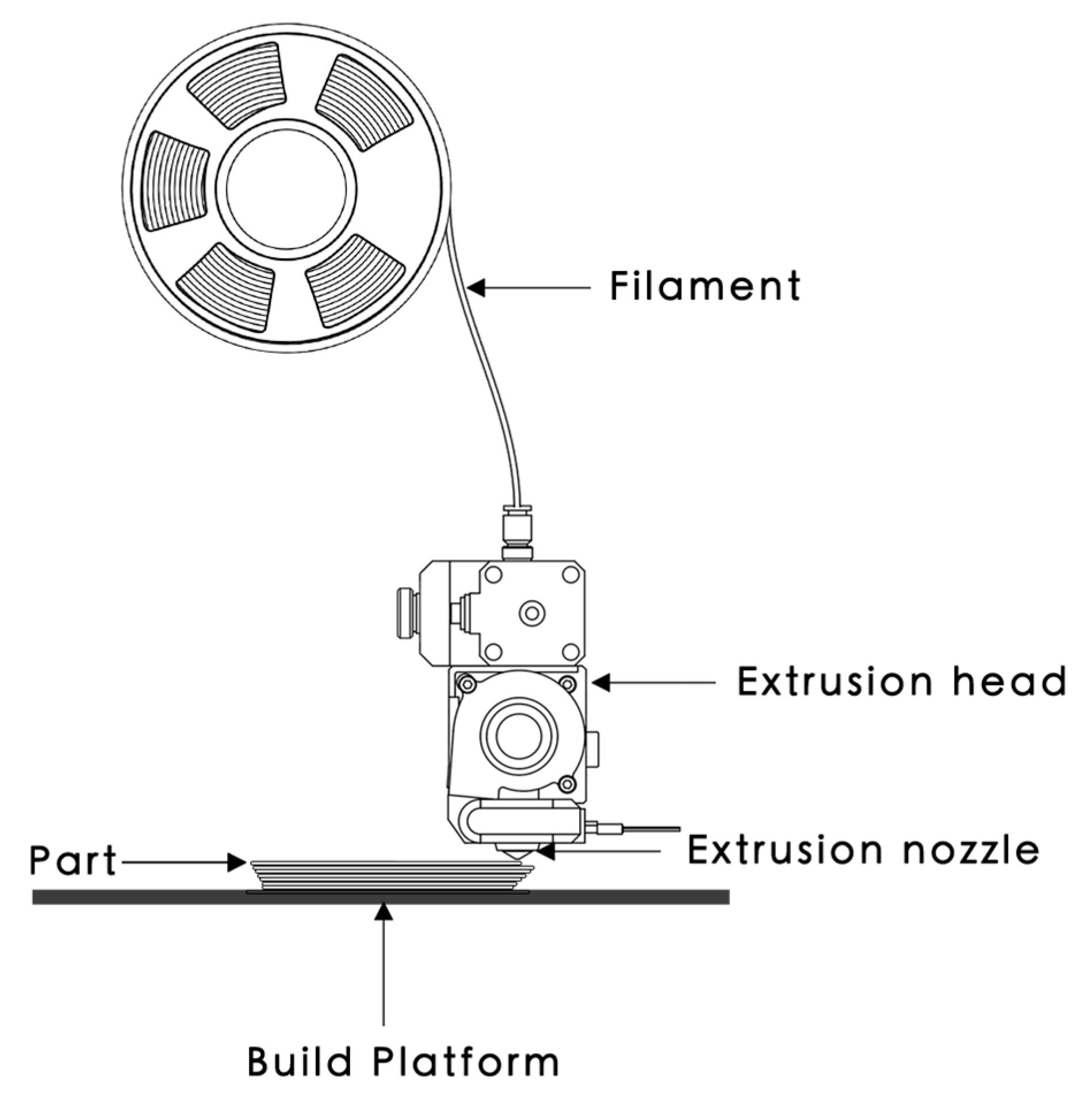
Material extrusion (ME) is the second most popular form of additive manufacturing (AM) process with 844,800 and 499,500 searches on Google as well as Google Scholar, respectively, after Powder Bed Fusion that has been searched 578,000 and 26,820,000 times, respectively. The term ‘ME’ was commonly searched together with ‘Fused Deposition Modelling’ and ‘Fused Filament Fabrication’. These three terms refer to the same AM process of additively building up material by selectively dispensing through a nozzle or orifice [1]. The technology involves the material from a spool of filament that is loaded into the printer, melted above its glass transition temperature (Tg) for amorphous polymers and above its melt temperature (Tm) for semi crystalline polymers to be selectively dispensed through the heated extrusion nozzle and deposited onto the build platform at a predetermined location (Figure 1) [2].
As the use of desktop ME machines has gained widespread adoption, this paper discusses several key design strategies and considerations to produce high quality ME parts and focuses on the current issues concerning the desktop ME process which is not machine specific. The purpose of this paper is to serve as a troubleshooting guide to determine and remedy common causes of problems and symptoms. This review summarizes the findings of many development engineers, researchers at equipment manufacturers, scientists, ME users and our personal experience available in the open literature. These findings were derived from working with desktop Cartesian printers that use a system of X-Y-Z coordinates to determine the location of the extrusion nozzle, but similar issues could also be encountered in Delta ME machines, Polar ME machines or extruders fitted to robotic arms.
Advantages and Disadvantages of ME
ME processes allow a wide variety of materials with diverse characteristics and properties to be used, ranging from commodities, engineering, to high-performance thermoplastics, composites, and functional materials (Table 1). Examples of commercially available commodity thermoplastics used in ME include polylactic acid (PLA), acrylonitrile butadiene styrene (ABS), high impact polystyrene (HIPS), styrene acrylonitrile (SAN), and polypropylene (PP). Examples of engineering polymers commercially available for ME include acrylonitrile styrene acrylate (ASA), polymethyl methacrylate (PMMA) polyamide 6 (PA6), polyamide 66 (PA66), polyamide 12 (PA12), polycarbonate (PC), thermoplastic polyurethane (TPU), polyethylene terephthalate with glycol (PETG), recycled PET (rPET), thermoplastic elastomer (TPE), polyoxymethylene copolymer (POM-C), thermoplastic copolyester elastomer (TPC), polyvinyl alcohol (PVA), polyhydroxyalkanoate (PHA), butenediol vinyl alcohol (BVOH), blended with PLA and other blends of polymers (Table 3) [3]. Examples of high-performance polymers available as filaments for ME include polyphenylsulfone (PPSF, PPS or PPSU), polyetherimide (PEI), polyamide imide (PAI), polyaryletherketone (PAEK), polyether ether ketone (PEEK), polyvinlydene floride (PVDF) [3]. Examples of composite filaments include Carbonyte (PA with carbon fibers), and other engineered polymers such as those with wood fibers, glass-filled fibers or particles, carbon fibers and magnetic particles like ferrites, as well as special polymer blends with ceramic, cement and metal for sintering applications [3,4].
ME processes offer end-users desktop equipment at a lower price range as compared to other AM technologies in the market as well as at a professional and industrial level for higher precision and performance components fabrication (Table 2). An open-source ME printer offers end-users the freedom to utilize third party filaments that fit the machine parameters, while a closed system limits the use to only materials offered by the printer manufacturer [18].
ME is useful to produce quick and low-cost prototyping with great freedom of scalability where parts can be printed in different geometries, quantities and sizes quickly [35]. However, ME is less suitable for producing intricate or miniaturized parts due to the circular profile of the print nozzle where the minimum nozzle size is 0.2 mm. As a result, corners and edges will have a radius that is equal to the size of the machine nozzle. Layers from the ME process are printed as a round-ended rectangle, in which the joints and seams between each layer are often visible as small valleys (Figure 2). These visible layers sometimes result in a stair-stepped effect and post-processing is required to achieve a smooth surface. Unlike the material properties achieved through subtractive or formative manufacturing, most ME parts are inherently anisotropic and not fully dense due to the nature of the layer-by-layer fusing of material. The bond and strength of the printed part are usually weaker along the plane of the layer interface [36]. ME parts may also encounter an issue with repeatability due to differential printer characteristics or inconsistency in printing conditions such as cooling or warping [2].
2. General Strategies to Achieve High Quality Parts
The quality and performance of parts produced by ME are highly dependent on the build parameters used. These parameters can be grouped into temperature-related parameters, infill, adhesion to the build platform and the orientation which are discussed in the following sections.
2.1. Temperature
The quality of parts being produced using ME is highly dependent on the optimum nozzle temperature. If the correct temperature is used, high-quality prints with smoother finishing, better clarity of details, better overhangs, and better bridging can be achieved. The temperature of the build platform should be properly set according to the material used. It is recommended that the build platform temperature should be above the Tg of the deposited material to enable sufficient adhesion [37]. The build platform heats up the surrounding environment and influences the contact between the deposited and depositing strands, which can affect the interlayer adhesion that may influence the mechanical properties of the produced parts. Please note that high-performance polymers often require an extruder that is capable of functioning above 300 °C and a heated chamber to prevent warpage or distortion during the printing process [2]. The use of a cooling fan is recommended for some materials since it can improve the geometrical accuracy of the printed parts by holding the deposited strands in place. However, mechanical performance may sometimes be affected when cold air is drawn into the print area using fans [38]. Table 3 provides a reference guide for the optimal nozzle and build platform temperatures based on different materials [39].
2.2. Infill Pattern and Density
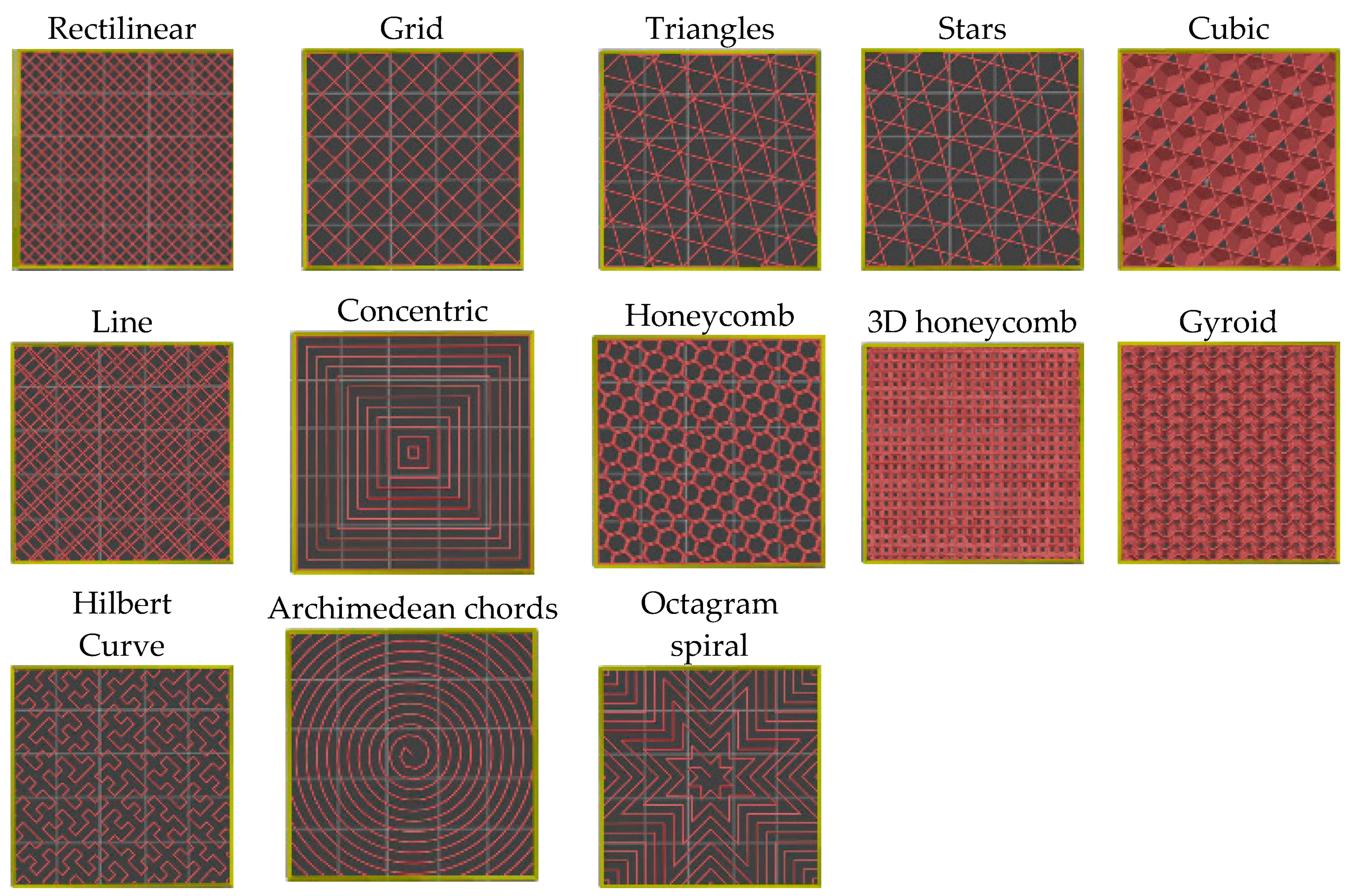
The right percentage of infill reduces the amount of print time and material usage, but this needs to be balanced with the overall strength of the part that is required. The infill pattern and infill density influence the mechanical performance of printed parts. In general, the mechanical performance of the printed part reduces when the infill density is lower. Slicing software such as Slic3r PE by Prusa Research offers end-users with up to 13 types of infill patterns as shown in Figure 3. The infill density can be set between a value of 0% and 100%, with 0% being hollow and 100% as being completely solid.
The common infill percentage used is 20%, enough to support flat ceilings with most thermoplastics. A 40% infill is usually sufficient to provide good mechanical strength, while 80% can be used to generate a tighter filled model for higher strength by using more material. [20]. The higher infill density generally provides better mechanical properties, although the choice of infill pattern can also make a difference. For example, the tensile properties of ABS have been investigated on printed specimens with 100% rectilinear, honeycomb and concentric infill patterns and it was observed that the rectilinear patterns provide the best results with the strongest parts, followed by the concentric pattern and the honeycomb pattern. When the density is reduced, a better tensile strength was observed with the honeycomb pattern for ABS specimens [52]. Similar results have been reported for PLA with tensile specimens filled to 10%; at this low infill, the linear pattern had the highest maximum strength, followed by hexagonal, and diagonal patterns. However, the elongation at break of the linear and diagonal was not significantly different and the hexagonal infill was significantly lower [53]. For PMMA specimens, it was observed that the 3D honeycomb infill pattern outperforms the rectilinear and gyroid infill patterns for infill densities from 30% to 70% when referring to impact resistance [54]. Therefore, selecting the infill parameters depends on the application of the part.
2.3. Additional Structures
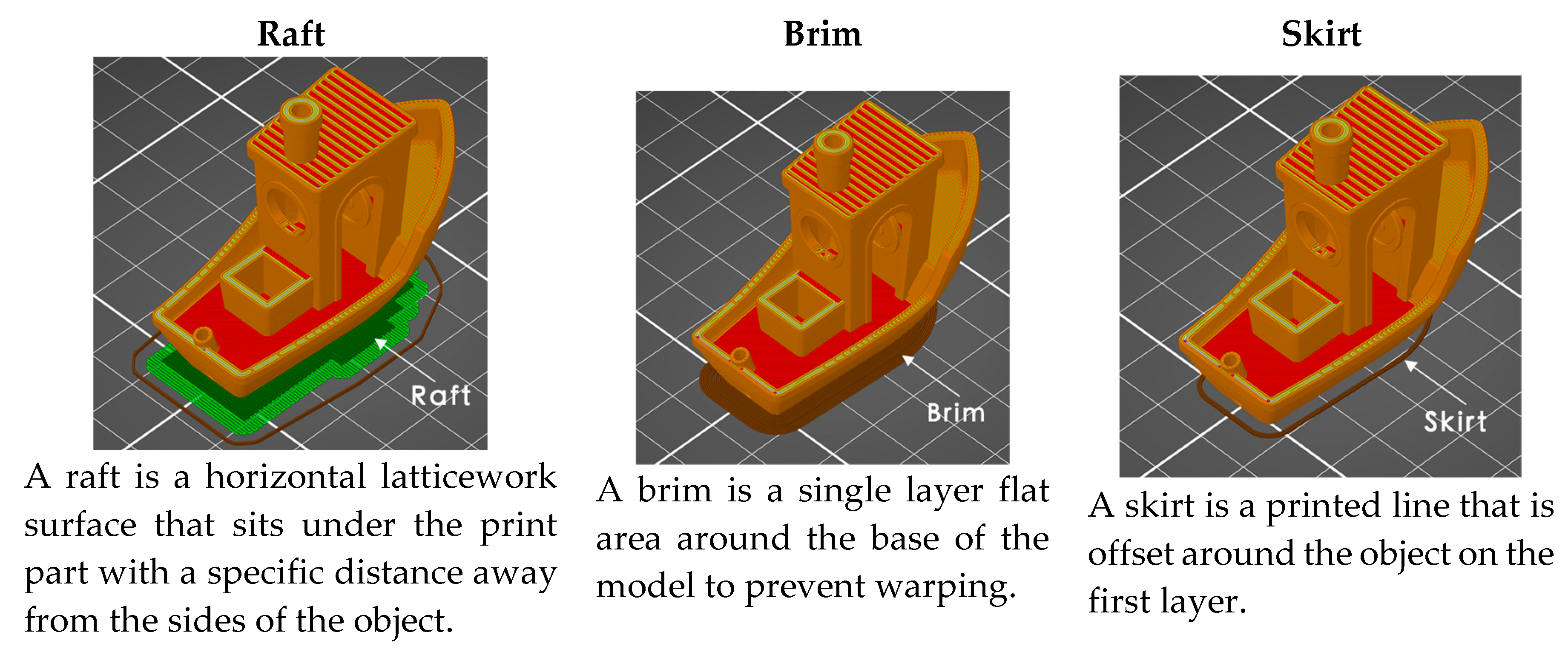
A key factor that can help improve the print quality of ME parts is to implement features such as raft, brim and skirt (Figure 4). The use of rafts and brims help to stabilize the printed part with a small surface area or footprint to improve adhesion and to reduce warping and delamination. A raft is made up of a predetermined layer of material with an adjustable infill percentage. It is first printed with a specific layer depth and with an optimal separation distance between the sitting model to aid part removal when the object cools. It can also be used to compensate for small inaccuracies in the build platform or for warped bed surfaces, scratches or dents [55]. The disadvantage of using a raft is that the model may be difficult to remove if the settings are not properly chosen. The lower layers may also have a different finishing result as compared to parts produced from printing directly onto the platform. A raft also consumes slightly more material and thus generates additional waste. As a result, the brim feature is often preferred [55]. A skirt consists of several layers of an outline that is offset away from the model. It is mainly used to ready or prime the extruder, and to also enable a final check for bed levelling issues and the quality of the filament being extruded before the print process commences. A brim feature is similar to a skirt, but it has a connected offset that is outward from the perimeter of the model. The brim can be used to prime the extruder as well as to enlarge the bottom surface area and hold down the edges of the model to improve the build platform adhesion. In the case of warping, the corners of the model are less likely to curl up or deform because the brim is attached to it. This is particularly useful when using materials that have a large shrinkage factor such as ABS or with semi crystalline polymers (e.g., PA12). The brim width is determined by the number of skirts that are built around the model [56].
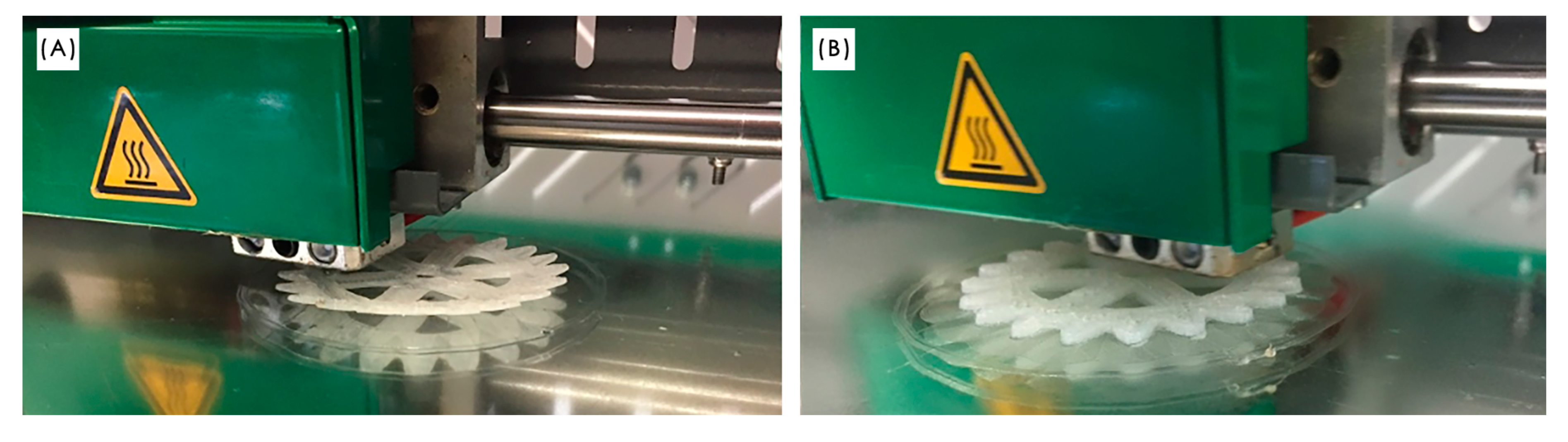
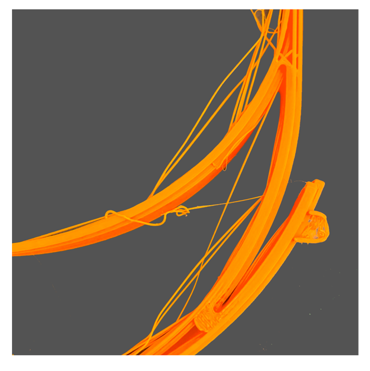
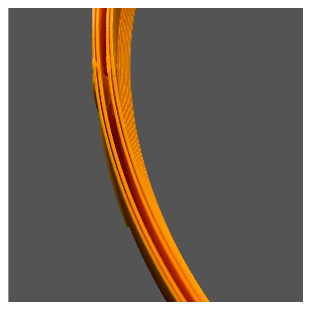
An example of how a brim can be used to keep a part attached to the build platform during the printing of PA12 on a glass surface is shown in Figure 5. PA12 is a semi crystalline polymer which shrinks significantly when it cools down. The shrinkage is strong enough to cause the part detaching from the build platform when only using a skirt (Figure 5A). If a brim is used, the part can be printed more successfully (Figure 5B).
2.4. Build Orientation
Due to the anisotropic nature of the ME processes, it is crucial to position the CAD model at the right orientation to achieve the most optimal mechanical performance. Parts printed using ME processes have inherently weaker tensile properties when the load is applied perpendicular to the direction of the deposition of strands. For example, ABS specimens tested perpendicular to the layers had only 74% to 79% of the tensile strength of specimens tested along the layers [58]. This is due to the lack of continuous material paths and the stress concentration created by each layer creates weaknesses where cracks are likely to form. The tensile strength is better when the load is applied perpendicular to the deposition direction of the strands as shown in Table 4 [2].
According to the general rule of thumb for ME, avoidance or minimal use of support structures is always recommended to reserve the best cosmetic surfaces. Strategies such as splitting a model, limiting the degree of overhang, minimizing overhangs and changing the build directions can avoid the use of a support structure which can help to reduce material usage, cost, increase the print speed, improve the strength and the final print quality of ME parts (Table 5) [59]. When a part alteration is not possible, an alternative way of eliminating overhanging features that require a large amount of support is to split the design model into half. The sections can be later joined at the post-processing stage.
3. Troubleshooting of ME Parts
This section discusses the most common problems encountered with the ME processes which have been categorized according to (3.1) printer-associated, (3.2) deposition-associated and (3.3) print quality issues (Table 7). This section also includes recommendations to overcome print failures and to improve print reliability. These results are derived using the Original Prusa i3 MK3 MR printer, Wanhao i3 duplicator and a Hage3D printer, as well as from existing literature [2,61,62,63,64,65,66,67]. The recommendations are not printer-specific and can be applied to most Cartesian based ME machines.
3.1. Printer-Associated Problems
3.1.1. Not Extruding at Start
The extruder is not extruding the material at the beginning of the print. This may be due to the extruder not being properly primed before the beginning of the print. It occurs when the nozzle height is set too low or too close to the build platform, the filament is stripped and/or having a clogged nozzle. Solutions include the following:
- Drawing a skirt to prime the extruder before starting the print.
- Check if there is a lot of plastic shavings caused by the drive gears (refer to 3.1.6: Grinding filament).
- Unclog the nozzle and check if there is any foreign debris or plug inside the nozzle. Clean the nozzle using a brass wire brush or replace with a new nozzle (refer to 3.1.4: Clogged nozzle).
3.1.2. Poor Adhesion of the First Layer
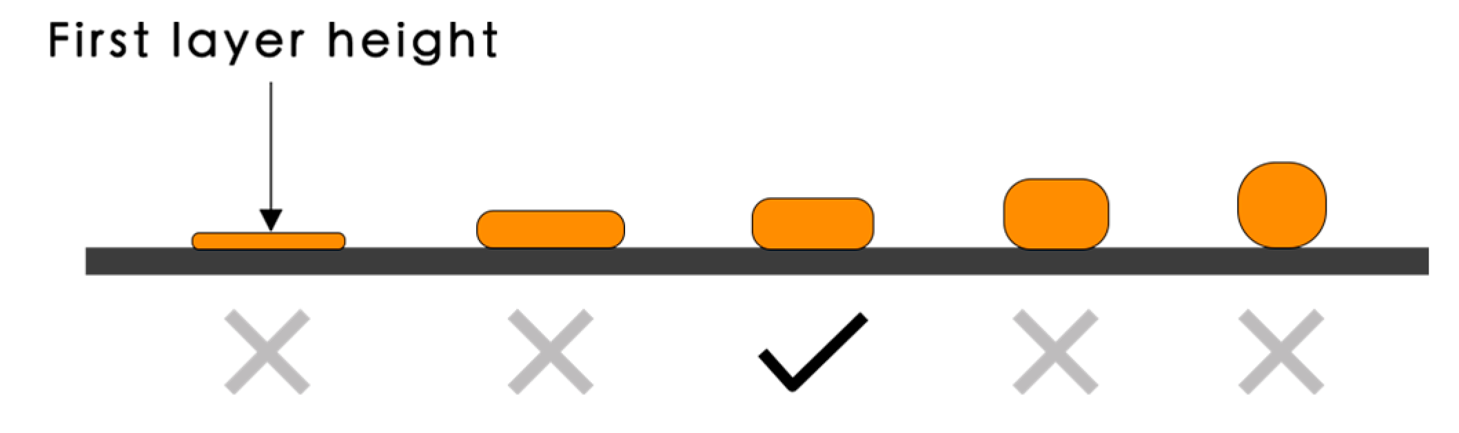
Having a successful first layer that adheres to the build platform is crucial to ensure a good print. The first layer of print that does not stick to the build platform may be due to an incorrect built platform levelling sequence, nozzle height set too high, first layer printing speed too high, and/or poor build platform adhesion due to the surface grease or residues from previous prints [37,68]. Solutions include the following:
- Decrease the first layer print speed. If the first layer speed is set at 50%, it could mean that the first layer will print 50% slower than the rest of the sections.
- Disable the cooling fan for the first few layers. Ensure that the recommended bed temperature is used.
- Increase the nozzle temperature by 5 °C for better adhesion or as recommended in Table 3.
- Check the extrusion settings to ensure that the right amount of plastic is extruded.
- Wipe the build surface using 90% isopropyl alcohol (IPA) solution or Acetone to remove residues from previous prints and to keep the surface grease-free. If the problem continues, improve the surface adhesion such as with a PEI sheet, blue painter’s tape for PLA, Kapton Tape for ABS or separate agent coatings such as glue stick or hair spray for PETG. Check if the material requires a special surface such as when using PP filaments [3,69].
- Increasing the roughness of the surface of the build platform by sanding or creating cleated surfaces [37].
- Printing an additional structure like a brim or a raft, as discussed in Section 2.3.
3.1.3. Stops Extruding during Mid Print
If the printer stops extruding during the middle of a print, this could be a result of running out of filament, a snapped or stripped filament against the drive gear, mid-print clogged nozzle, an overheated extruder motor driver, and/or a file or CAD file or G-code error. Solutions include the following:
- Replacing a new spool of filament. Newer and more expensive printers have a position sensor that stops the printing job when no filament is detected.
- Replace the snapped filament and/or reduce the idler tension by loosening the filament if it is too tight or if there is a lot of plastic shavings or debris caused by the drive gears (refer to 3.1.6: Grinding filament).
- Remove the filament and run through a diagnostics test to confirm that fans are functioning properly. Ensure that the hot-end fan is attached properly. It should direct the air inside while spinning. Check that all wires are still connected to the correct place.
- Ensure that the printing temperature is correct for the loaded filament. Make minor temperature adjustments of ±5 °C. Alternatively, use a different filament to check if the clog is caused by the current filament that could be out of acceptable tolerance.
- Turn off the printer to allow the electronics to cool down and check the cooling fan. Overheated motors can cause the printer to shut down.
- Check the generated G-code, preview the slices using the slicing software. Repair any errors on the .STL File, or upload a new file if necessary.
3.1.4. Clogged Nozzle
A sign of clogged nozzle is that the filament is only extruding a little and does not curl nicely or do not extrude anything at all. It is usually caused by an incorrect print temperature that results in the material buildup, due to a malfunctioning fan or build-up of old materials, especially when dealing with composite materials. Solutions include the following:
- If the filament is not extruding at all, heat the nozzle to the recommended print temperature for the loaded filament. Push a small needle into the nozzle and repeat until the plug unclogs. Reload a new filament to observe if the filament can extrude smoothly.
- Check that there are no loose or broken wires from the main-board to the extruder assembly, check the transistors of the main-board. Replace the wires or the main-board if required [71].
- When the clog is due to material build-up, replace the nozzle with a new one; clean the old one with a suitable solvent.
3.1.5. Caked Nozzle or Extruder Blob
Caked or extruder blobs that occur within the first five minutes of the print could be due to the nozzle catching on a lifted piece of print. Solutions include the following:
- Monitoring the print for the first five to ten minutes before leaving the print to make sure that the first layer is sticking well onto the build platform.
- To remove the extruder blob, heat the nozzle according to the material used. This allows the block of plastic to soften up while carefully pulling out the blob. It is important to be extra cautious around the thermistor wires when doing this.
- Use a plier and a brass brush to thoroughly clean the nozzle.
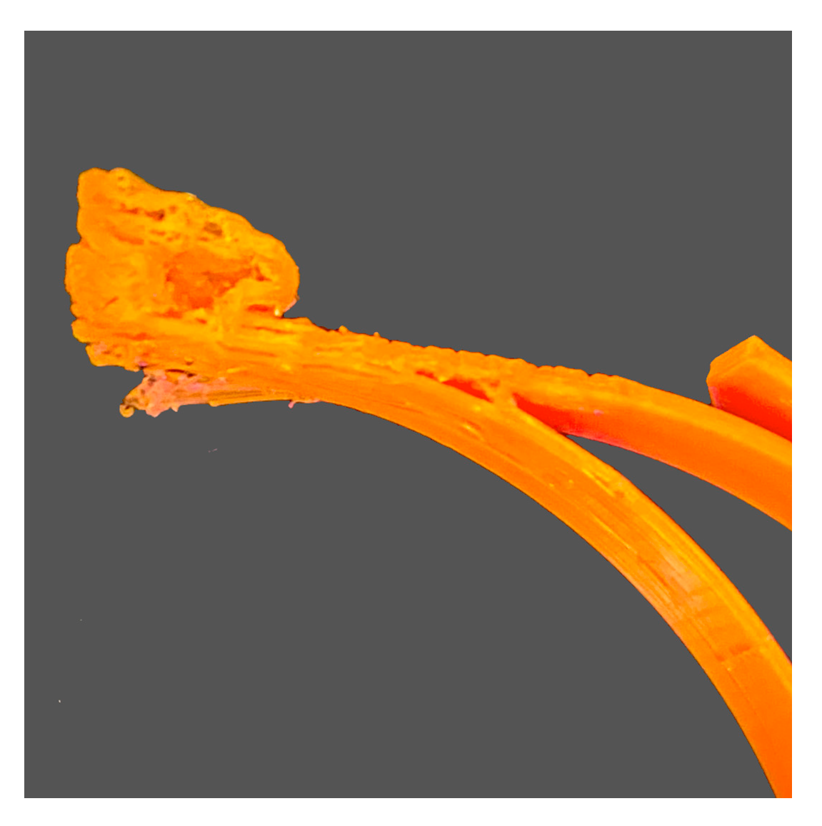
3.1.6. Grinding Filament
Grinding or stripping of filament refers to excessive shaving of plastics, causing the gear teeth to have little material to grab onto (Figure 7). The contributing factors include if the retraction setting is set too fast, the printing temperature is too low, the printing speed is too high, overtightened extruder, dirty extruder gears, jammed filament tubes, and/or a clogged nozzle. Solutions include the following:
- Reducing the retraction speed by 50%. Excessive stress will be applied on the extruder if the retraction speed or the distance is set too high.
- Increase the nozzle temperature by 5 to 10 °C to reduce the viscosity and better flow of the material.
- Use a slower printing speed or decrease the default printing speed by 50%. This reduces the rotation of the extruder motor which may be the cause of the grinding issue.
- Make sure that the tension of the extruder idler wheel is correct as an over-tightened idler cannot push the filament towards the nozzle [72].
- Remove any plastics residue with pliers or using a pin.
- Open the extruder idler wheel to inspect if there is any debris in the tube that may inhibit the flow of filament.
- Unclog the nozzle (refer to 3.1.4: Clogged nozzle).
3.1.7. Extrusion Away from Previous Layers: Spaghetti Monster
A spaghetti monster occurs when the model detaches from the build platform during mid-printing and the deposited material stops sticking to the object (Figure 8). This could be a caused by poor build platform adhesion and/or a CAD file or G-code error. Solutions include the following:
- Make sure that the first layer sticks entirely onto the build platform. Increase the bed temperature by 5 °C for better adhesion (refer to 3.1.2: Poor adhesion of the first layer).
- Detect any CAD file or object error to observe if there is any gaps or broken geometry in the .STL file. Check the generated G-code, preview the slices using the latest slicing software. Repair any errors on the .STL file if required.
3.2. Deposition-Associated Issues
3.2.1. Under-Extrusion
Under-extruded areas will show visible gaps. There will be material missing in or between the print layers. Under-extruded objects will be fragile and may easily break. This is usually due to hardware problems such as a loose extruder gear, dirty extruder gears, poor quality filament with diameter fluctuations, incorrect extrusion multiplier setting, and/or slicing errors if manual adjustments have been made. Solutions include the following:
- Making sure that the extruder gear is correctly tightened (refer to 3.1.6: (4) Overtightened extruder idler).
- Clear any plastics with the sharp corner of a plier or with a durable pin (refer to 3.1.6: (5–6) Dirty extruder gears).
- Poor quality filaments may have inconsistent diameter tolerances that often lead to a clogged nozzle. Use a caliper to measure the consistency of the filament diameter. The diameter difference should not exceed ± 0.05 mm. Replace the filament or use a better-quality filament if necessary.
- Tune the extrusion multiplier settings only if the under-extrusion is not caused by a hardware issue. Increasing the extrusion multiplier consequently increases the flow of the filament into the extruder. Decreasing the extrusion multiplier will also slow down the flow of the filament into the extruder.
- Check the generated G-code, preview the slices using the latest slicing software. Repair any errors in the .STL file and make adjustments in slice settings if necessary.
3.2.2. Over-Extrusion
The printer is extruding more plastic than the software expects, thereby forming print blobs. Over-extrusion affects both dimensional accuracy and the aesthetics of the printed object. It could be due to high extrusion multiplier settings, and/or the printing speed set too high. Please note that sometimes a bit of over extrusion can be beneficial for the mechanical properties of the material since some of the porosity can be filled by over-extruding [73]. However, over-extrusion should be done carefully so as not to affect the dimensional accuracy of the part. Solutions include the following:
- Reconfiguring the extrusion settings by decreasing the extrusion multiplier setting (refer to 3.2.1: (4) Incorrect extrusion multiplier setting).
- Reduce the filament flow rate.
3.2.3. Overheating
The print looks melted or deformed. Overheating may be a result of insufficient heat dissipation, printing temperature set too high, and/or printing speed set too fast. Solutions include the following:
- Increasing the power of the cooling fan to allow faster cooling of the plastic. Alternatively, try multiple prints per batch to allow longer cooling time for each model, while printing subsequent models in the same bed.
- If the cooling fan is on, reduce the printing temperature by 5 to 10 °C.
- Reduce the printing speed, especially for small models to allow each layer to cool down properly.
3.2.4. Small Features Not Printed
Most ME printers use a 0.4 mm nozzle which will not generate a solid perimeter for extremely thin features with dimensions smaller than 0.4 mm. It is best to avoid setting the dimensions of a CAD model to be less than the nozzle size. Redesign the part to have thicker features above the minimum printable dimension. Solutions include the following:
- Increasing the dimension of the part to be more than the nozzle size.
- Enable single wall extrusion by selecting detect thin wall.
- Lower the print speed while printing intricate details such as text.
- Install a nozzle with a smaller tip size if the size of the model cannot be modified and re-slice the model with the new nozzle diameter.
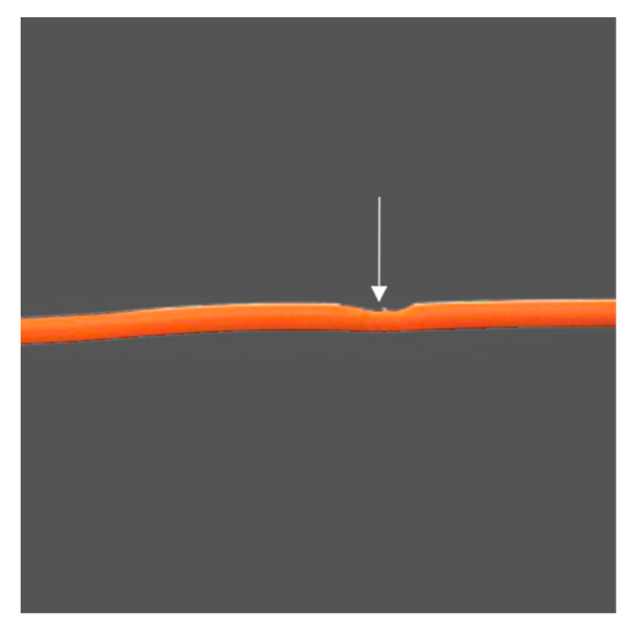
3.2.5. Inconsistent Extrusion
Inconsistent extrusion of the material may result in a bumpy surface that may affect the quality and dimensional accuracy of the printed object (Figure 9). The contributing factors could be tangled or stuck filament, a semi-clogged nozzle, nozzle height set too low, incorrect extrusion width, poor quality filament, and/or having an overtightened extruder idler wheel. Solutions include the following:
- Making sure that the filament is feeding into the printer. There should not be too much resistance to stop the filament spool from moving freely and pulling into the printer (Refer to 3.1.6: Grinding filament).
- Remove any foreign debris in the nozzle (refer to 3.1.4.: Clogged nozzle).
- Recalibrate the build platform (refer to 3.1.2: (1) Incorrect built platform levelling).
- Make sure that the extrusion width is set at 100% or 150% greater than the default nozzle diameter of 0.4 mm. The printer will struggle to extrude any width less than the nozzle diameter (refer to 3.2.4: Small features not printed).
- Make sure that the filament is not degraded. Replace the filament that may be at fault and use a better-quality filament (refer to 3.2.1: (3) Poor quality filament with diameter fluctuations).
- Make sure that the tension of the extruder idler wheel is correct (refer to 3.1.6: (4) Overtightened extruder idler wheel.
3.2.6. Dimensional Accuracy
The measurement of the printed object differs from the CAD model. For example, the holes may be in the wrong size; parts do not align or do not fit together. Lack of dimensional accuracy creates a fitting problem while assembling other parts of the model. Inaccurate or incorrect dimensions could be due to incorrect measurements in the CAD model, not adhering to design rules, layer height issues, issues with the belt movement or loose pulley, and/or material shrinkage. Solutions include the following:
- Check the physical and working unit of measurements of the CAD model especially when using the .STL file format. Ensure that correct and identical unit selection (mm or cm) is used for the CAD and slicing software.
- Set proper tolerances such as 0.5 mm clearance for fixtures like male and female connectors, screws, holes and snap fits.
- Test the printer accuracy by printing a cube of 50 mm × 50 mm. Keep a consistent height for all print samples. Use a digital caliper to check that the measurements are equal. If not, measure the top 20 layers which should be equal to 20 mm. If this is still correct, but the overall height is wrong, then it is likely that the first few layers are causing the issue. Investigate the height of the extruder. If the extruder height is 1 mm from the print platform, but the printed layer height is 2 mm, then this could be happening because there is too much filament being laid down on the first layer. Recalibrate the printer, run through first layer calibration with a suitable layer height (refer to 3.1.2: (1) Incorrect built platform levelling).
- Recalibrate X-Y axes. Check if all belts and rails are tight and screwed into place. If the printed hole looks oval, this could be due to a loose belt or slight misalignment on the X and Y- axis (refer to 3.2.7: (1–2) Improper axis movement and (3) Loose pulley).
- A 1-mm reduction in size could be due to material shrinkage after cooling. Calculate the percentage of error and increase the scale of the print to compensate for the shrinkage.
3.2.7. Shifted Layers or Leaning Prints
Layer shifting is a result of improper axis movement, causing the extruder to misalign during mid-print (Figure 10). This includes a movement being blocked on the axis, a loose pulley causing the layer shift, and/or due to a geometry that is difficult to print. Solutions include the following:
- Check the tightness of X and Y belts. When plucked, the belts should sound like a low bass note. The back of the X-carriage should not be loose. Check and tighten all screws.
- Ensure that there is no obstruction in the path of the bearing, or any possible waste stuck around the belt.
- Check the tightness of X and Y pulleys. Ensure that the pulley on the motor shaft is secure and the idler pulley can move freely on the opposite end.
- Design according to the guidelines and rules for ME to avoid geometry that is difficult to print, particularly for models with large overhangs that tend to warp during mid-print.
3.2.8. Lower Parts Caving in
The lowest parts of the print appear to shrink before reaching the proper dimension due to insufficient heat dissipation and/or an incorrect platform temperature. Solutions include the following:
- Increase the cooling fan power to allow faster cooling of plastic (refer to 3.1.2: (3) Incorrect bed temperature or cooling settings; 3.2.3: (1) Insufficient heat dissipation).
- Adjust the right bed temperature for proper layer adhesion to the build platform and to prevent the print from shrinking before reaching the intended dimensions (Table 3).
3.2.9. Skipped Layers
Some layers are shown to be missing and visible gaps appear on the printed object. This could be due to under-extrusion because of an inconsistent diameter of the filament, extruder issues caused by the feeder wheel, misaligned or shifted rod, a worn bearing, and/or a semi-clogged nozzle. Solutions include the following:
- Using a caliper to reconfirm the consistency of the filament diameter. The diameter difference should not exceed ± 0.05 mm (Refer to 3.2.1: (3) Poor quality filament with diameter fluctuations).
- Run a mechanical check and inspect all moving parts. Oil the joints using a suitable lubricant.
- Ensure that all rods are properly seated into the bearings or clips. The rods should not pop out, shift or bend. Switch off the power and move the print head along the axis. If there is resistance, further inspection is required.
- worn bearing will create an audible din and uneven motion of the print head. Switch off the printer and move the print head along the axis to locate the broken bearing.
- Remove any foreign debris in the extruder (refer to 3.1.4: Clogged nozzle).
3.2.10. Print Bows Out at the Base
The bottom of the model bulges outwards, known as an elephant foot could be the result of the weight of the part pressing downwards before the layers below have cooled down into a solid and cannot support the structure due to insufficient heat dissipation. Other factors include the platform temperature set too high, and/or the nozzle is too low. Solutions include the following:
- Adding a 5 mm 45° angled chamfer to the base of the model.
- Increase the cooling fan speed to allow faster cooling of plastic in the built regions (refer to 3.1.2: (3) Incorrect bed temperature or cooling settings; 3.2.3: (1) Insufficient heat dissipation).
- Lower the bed temperature gradually by 5°C each time but no greater than 20 °C [61].
- Adjust the first layer height by calibrating the first layer (refer to 3.1.2: (1) Incorrect built platform levelling).
- Print more parts at once to allow for the layer to cool down before the subsequent layer is deposited (refer to 3.2.3: (1) Insufficient heat dissipation).
3.2.11. Random or Messy Infill
A broken or missing internal infill may affect the structural integrity of the model. The most common reasons are due to incorrect infill density, semi-clogged nozzle, and/or the type of filament used. Solutions include the following:
- Changing the infill density. A density value of 40% is usually sufficient for most models to achieve good mechanical strength; 50% will generate a tighter filled model using more material; 20% is usually the minimum required to support flat ceilings [74], but this can change depending on the material being used.
- Remove any foreign debris that is preventing proper extrusion (refer to 3.1.4: Clogged nozzle).
- Flexible filaments are vulnerable to imperfect infills. The grid infill pattern is the best option when using flexible materials.
3.2.12. Stringing or Oozing
Stringing or oozing occurs when marginal lines of plastic are left behind or in between the objects while the nozzle moves to another point due to incorrect retraction settings, a loose belt, printing temperature set too high, and/or poor quality filament being used. Solutions include the following:
- Ensure that all tension belts are tightened.
- Lower the printing temperature by 5 to 10 °C.
- Post-process the parts to remove strings by using a heat gun. For PLA and ABS parts, set the heat gun at 200 °C to melt the strings and the printed object should remain undamaged (refer to 3.3.19: Hairy prints).
3.2.13. Poor Bridging or Ugly Overhangs
Bridges are stretches of plastic extruded between two raised points. Poor overhangs occur when the printer is printing material in thin air due to lack of support, or there is nothing to deposit above. Solutions include the following:
- Using supports for overhangs angle greater than 45° and bridges over 10 mm [2]. The bridging gaps should not exceed 5 mm to ensure minimal sagging of parts.
- Design according to the guidelines and rules for ME to avoid geometry that is difficult to print, particularly for models with large overhangs that tend to warp during mid-print.
- Consider changing the build orientation to avoid the need for an overhang.
3.3. Print Quality Problems
3.3.1. Walls Not Touching
Walls are either partially touching or not touching at all. If the walls do not fuse, the printer is most likely encountering under-extrusion due to a thin wall problem limited by the nozzle size, and/or a loose belt (Figure 11). Solutions include the following:
- Resolving the under-extrusion issue (refer to 3.2.1: Under-extrusion).
- Ensure that the wall thickness is in relation to the size of the nozzle. The wall thickness should be a multiple of the diameter of the nozzle thickness. For example, a 0.4 mm nozzle should have a wall thickness of 0.4 mm, 0.8 mm or 0.12 mm. If a 0.10 mm wall is used, two perimeters walls of 0.4 mm, giving a total of 0.8 mm will be created. This results in a 0.2 mm gap between the walls.
- Walls partially touching can also be due to a loose belt. Ensure that the belts are tightened.
3.3.2. Gaps between Infill and Outline
There are visible gaps on the print between the infill and the wall, in which they do not meet or bond together. This is usually due to the infill overlap not set or set at 0, having an incorrect print order of infill and outer perimeters, the type of filament used, and/or the nozzle height set too high. Solutions include the following:
- Changing the infill or perimeter overlap from the default 15% to 30%. This setting is directly linked to the extrusion width. When adjusting this setting, keep it below 50% to prevent any overlap on the outer perimeter of the print.
- Reverse the printing instruction to “inside-out” by printing the infill before the perimeter shell. For thin models, print the perimeter first with a minimum wall thickness to avoid the infill from ghosting on the surface (refer to 3.3.7: (1) Prints with thin wall structure).
- Gaps can be due to the type of filament used. This is more commonly encountered when using advanced materials. Increase the printing temperature by 5 to 10 °C and reduce the print speed on the top layer to avoid gaps.
- If gaps occur on the first layer, recalibrate the build platform to decrease the Z-distance (refer to 3.1.2: (1) Incorrect built platform levelling).
3.3.3. Gaps between Thin Walls
Gaps may occur between thin walls due to the slicing software that does not generate enough path to fill the part properly, and/or due to slicing software errors. Solutions include the following:
- Making sure that the print region can fit both outer shells and infills. The infill should be in multiples of the diameter of the nozzle size. Enable thin wall options for finer details and change the infill/perimeter overlap from the default 15% to 30% (refer to 3.3.1: (2) Thin wall problem limited by the nozzle size).
- Try the use of an alternative slicing software.
3.3.4. Sparse Top Fill
The top layers of the print are not completely solid. There are gaps and holes between the extrusion paths for the solid layers. This could be due to not having sufficient solid layers on top of the hollow infill, the infill percentage is set too low, and/or having under-extrusion. Solutions include the following:
- Ensuring that the top solid layers are at least 5 mm thick. If each layer height is 0.25 mm, then two layers are required; for 0.1 mm, five layers are required.
- The extruded solid layer may droop or sag if there are no supports. Increase the infill percentage to create a better foundation for the top solid layers.
3.3.5. Sparse Bottom Fill
Lines on the first layer may be overly visible or spaced apart due to the nozzle height set too high, and/or having an incorrect first layer height. Solutions include the following:
- Calibrate the first layer or recalibrate the build platform (refer to 3.1.2: (1) Incorrect built platform levelling).
- Adjust the first layer height to ensure that it matches the level of the build platform (0.2 mm default, minimum 0.15 mm) [65].
3.3.6. Messy First Layer
The first layer is messy or undesired lines are shown on the bottom surface of the part due to adhesion issues on the build platform, incorrect build platform levelling, or the print temperature is too high if the fine details on the bottom layer are not crisp. Solutions include the following:
- Wiping the build surface using 90% IPA solution or acetone to keep the surface grease-free.
- Use an alternative build platform surface (refer to 3.1.2: (5) Poor build platform adhesion).
- Run through the calibration of the first layer or recalibrate the build platform (refer to 3.1.2: (1) Incorrect built platform levelling).
- Lower the printing temperature gradually by 5 °C each time until the details appear crisp.
3.3.7. Visible Infill from the Outside: Ghosting
Ghosting occurs when the infill structure encroaches into the path of the perimeter (Figure 12). This problem is most likely to occur on prints with thin walls, or due to incorrect wall or shell thicknesses. Solutions include the following:
- Printing the model from ‘outside-in’ by building the perimeter, followed by the infill for good surface finishing.
- Double the wall or the shell thickness. Ensure that the wall thickness is in relation to the size of the nozzle used. It should be a multiple of the nozzle thickness (refer to 3.3.1: (2) Thin wall problem limited by the nozzle size.)
3.3.8. Visible Lines on the Side of the Print
Visible lines appear on the side or across the top layer of the print, often diagonally from one side to another. This may be due to incorrect print settings, combing, scratching scars caused by dragging of the nozzle, and/or over-extrusion. Lower quality filaments also tend to ooze from the nozzle due to the residual heat of the extruder, leaving a trail as the nozzle shifts. Solutions include the following:
- Checking the extrusion flow rate. Reduce the print flow by 5% and print a calibration cube to check if the issue is solved. Ensure that the filaments are extruding correctly to avoid under-extrusion or over-extrusion (refer to 3.2.2: Over-extrusion).
- Combing allows the nozzle to run over the printed area to substitute the need for retractions, but this may cause scarring of the part. Turn off combing will curb the problem but may lead to longer print time. Increase the amount of retraction if this issue continues after combing is turned off.
- Scaring occurs when the nozzle is set not high enough (refer to 3.1.2: (1) Incorrect built platform levelling).
- Adjust the extrusion temperature for lower quality or older filaments which may have been exposed to sunlight or moisture over a period of time as their tolerance to the print temperature may be reduced. Decrease the hot end temperature by 5 °C and repeat until a good result is obtained.
3.3.9. Scars or Scratched on Top Surface
Scars or scratches on the top surface of the print could be caused by the dragging of the nozzle across the top surface when moving across perimeters, low nozzle height, and/or over-extrusion. Solutions include the following:
- Using a vertical lift feature (‘Z-hop feature’ in the slicer) when changing location to avoid scars on the top layers and avoid crossing over of the perimeter settings.
- Scaring occurs when the nozzle is not high enough (refer to 3.1.2: (1) Incorrect built platform levelling).
- Reduce the extrusion multiplier (refer to 3.2.2: Over-extrusion).
3.3.10. Poor or Rough Surface above Support
Poor surface finish can sometimes be due to material remaining on the surface above the support structures. Check the support placement and select the most suitable support structure to achieve the right balance between strength and ease of removal [62]. Solutions include the following:
- Ensuring that the top surface of the support is clean before the final layer is deposited.
- Experiment with the use of tree-like supports, linear supports or create custom supports in Meshmixer [77]. Test to see if the object could be printed without support structures (refer to 3.2.13: Poor bridging or ugly overhangs).
- Consider changing the build orientation to avoid the need for supports.
3.3.11. Uneasy Support Removal
Support material can be difficult to remove if they are fused too tightly with the model. This could be due to having no gaps or insufficient layer height offsets between the surface of the support and the part, the pattern spacing being too tight, support percentage set too high, and/or an unsuitable support pattern that has been used. Solutions include the following:
- Using soluble support materials recommended in Table 3, particularly for dual extrusion ME printers.
- Increase the air gap or Z-distance between the support and the part.
- Increase the spacing of the pattern.
- Decrease the percentage of support.
- Create custom support if the support generated by the slicing software is intrusive or hard to remove.
3.3.12. Pillowing
The top surface of the model is not entirely closed or shows bumps. This could be due to having an incorrect top or bottom thickness, incorrect cooling settings, print temperature set too high, and/or printing speed set too high. Solutions include the following:
- Increasing the thickness of the top layers to prevent holes from occurring on the top surface.
- Ensure that the extruder fan head fans are running at the maximum fan speed to properly cool the top surface.
- Lower the printing temperature but also ensure that it does not under-extrude (refer to 3.2.3: (2) Printing temperature too high).
- Reduce the print speed (refer to 3.1.6: (3) Printing speed too high).
3.3.13. Blobs and Zits
Blobs and zits are marks that appear on the outer shell surface of the part, at times within a specific location where the nozzle starts to deposit and return (Figure 13). Examine the deposition to check if the blobs appear at the starting point or at the end of each layer. Solutions include the following:
- Having proper retraction and coasting settings.
- Selecting the best location for the deposition point.
- Blobs that appear in the beginning could indicate that the extruder is priming too much plastic. Use a higher retraction setting with an extra length when restarting the print. This option determines the retraction distance when the extruder is stopping as well as the priming distance used when the extruder restarts. Reduce the priming distance by adding a negative value for the extra length during restart. For example, if the retraction distance is 1.0 mm, and the extra length of restart distance is −0.2 mm, each time when the extruder stops, it retracts 1.0 mm of material. As the extruder starts to extrude, it will only push 0.8 mm of plastic into the nozzle. Adjust this setting until the defect no longer occurs when the extruder initially begins printing the perimeter [78].
- If blobs appear at the end of a perimeter, turn on the wipe before retracting feature (Slic3r PE) or coasting (Cura) to enable the nozzle to move to the next starting point while the extruder retracts. Adjust the value between 0.2 and 0.5 mm [78].
3.3.14. Irregular Circles
Printed circles may appear misshapen, oval or lines that are not properly touching. Irregular circles may be a result of an alignment issue, different belt tensions, differing step values entered for the X and Y axes, and/or blobs affecting the shape. Solutions include the following:
- Checking the unit measurements used in the slicing software to ensure all axes have the correct input.
- Check the Z-scar to prevent blobs altering the circle shape (refer to 3.3.13: Blobs and zits).
- Refer to 3.2.7: Shifted layers or leaning print, to counteract alignment issues.
3.3.15. Vibration and Ringing
Visual waves or rippling effect can sometimes be seen on the print surface, also known as echoes in print is usually caused by vibration due to an unsteady 3D printer, worn linear bearings, loose print heads, unsmooth axis movement, and/or print speed set too high. Solutions include the following:
- Placing the printer on a sturdy surface to reduce vibration.
- Make sure all bearings are running smoothly, all the bolts and joints are secured and correctly tightened.
- Check that all axes or rods are clear of dust and lubricated with oil for smooth movement (refer to 3.2.7: Shifted layers or leaning print).
- Reduce the printing speed or increase the flow and extrusion temperature.
3.3.16. Warping
The corner of the printed object is lifted from the build platform. Warping is often experienced when printing ABS, high-performance polymers (PEEK, and PSU) and semi crystalline polymers (PP and PA), due to an immediate change between the extrusion and the ambient temperature, causing an uneven plastic shrinkage and bend, greasy build surface, and/or infills and walls set too high. Solutions include the following:
- Keep a consistent ambient temperature. An open window or a cold environment will increase the chance of warping. Printing in an enclosed room can reduce the risk of warping. Alternatively, build an insulating chamber around your printer.
- Keep the build surface grease-free. Cleaning the surface with 90% IPA solution, acetone or a glass cleaner (e.g., Windex).
- Use a different build surface to increase surface adhesion such as blue tape (refer to 3.1.2: (6) Poor build platform adhesion).
- Reduce the infill percentage to less than 20%. A high infill percentage increase the stress on the model causing them to warp. Avoid using more than two to three walls in the model or use a brim.
3.3.17. Layer Separations, Cracks or Splitting
Cracks are more prominent on taller models considering the greater amount of airflow around the model. This could be due to an accelerated cooling at one side of the model or low printing temperatures leading to partials cracks due to a weaker bond. Solutions include the following:
- Keep a consistent ambient temperature or use an enclosure or a breeze shield to prevent strong airflow from affecting the print.
- Increase the nozzle temperature by 5 to 10 °C to reduce the viscosity and improve the layer from bonding.
3.3.18. Curling or Rough Corners
Curling or rough corners are usually due to overheating. The printed layers have not cooled down properly resulting in deformation before solidification. If curling occurs at the beginning of the print, it is usually due to warping. Solutions include the following:
- Refer to 3.2.3: Overheating.
- Refer to 3.3.16: Warping.
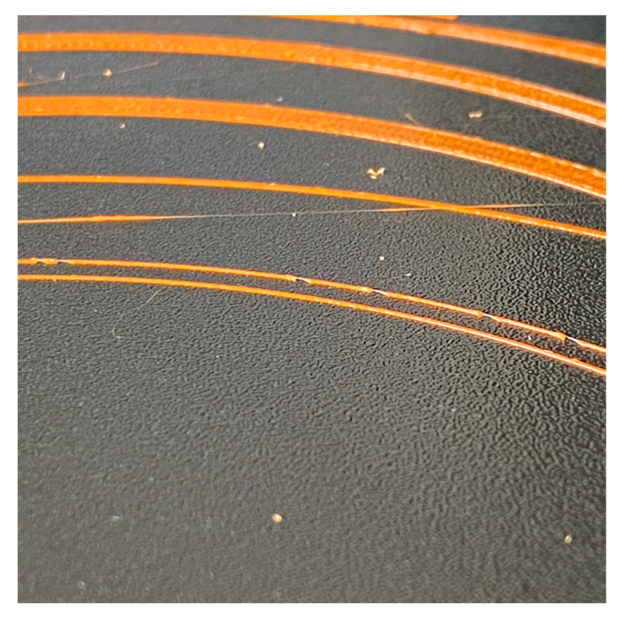
3.3.19. Plastic Threading: Hairy Prints
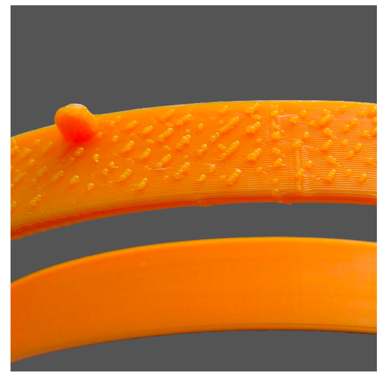
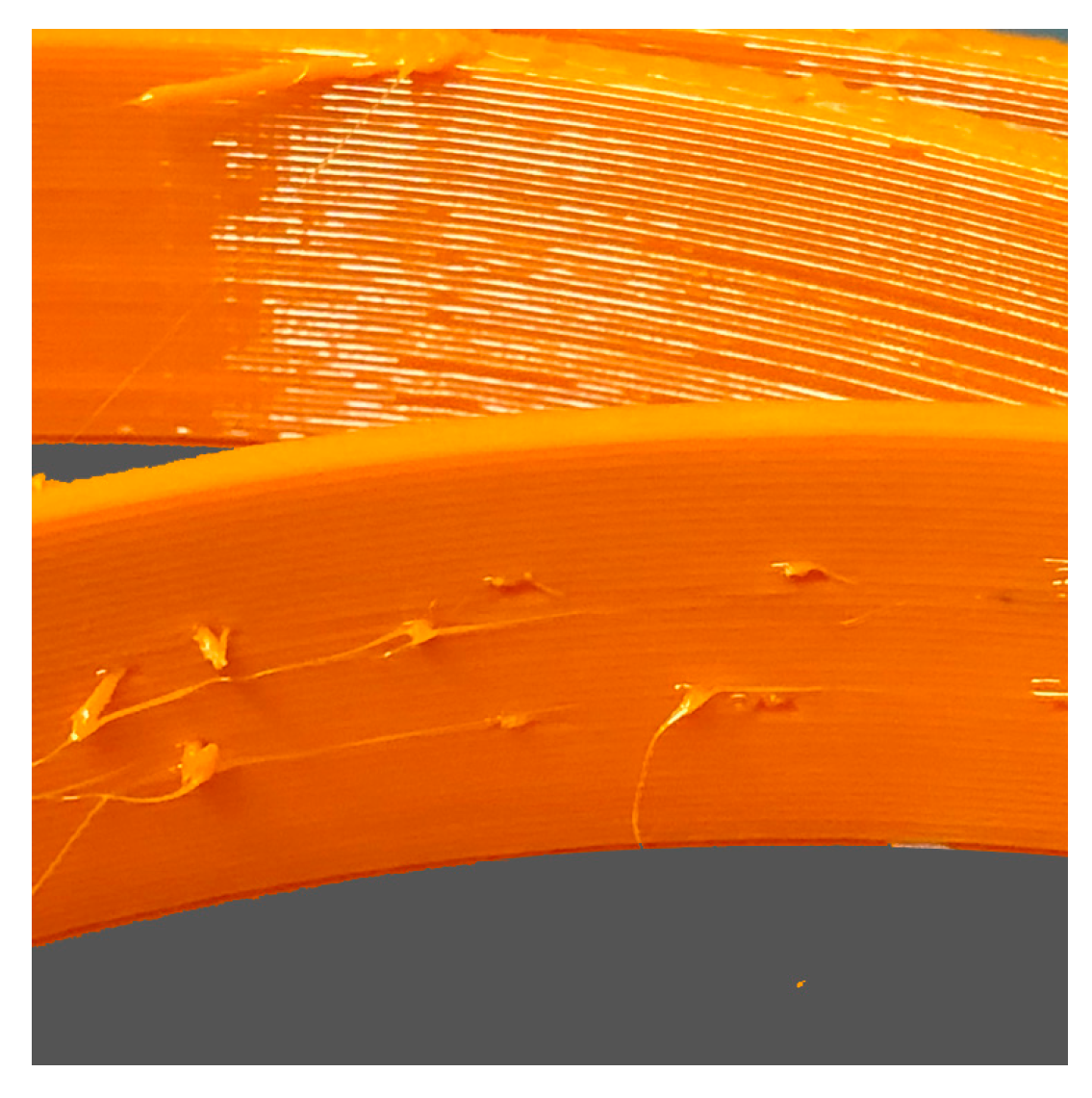
Hairy prints are usually a result of thin strands of plastic threading onto the object. This is different from 3.2.12 stringing or oozing. Hairy prints often appear even when there are no crossing voids and may be caused by the type of material used. Solutions include the following:
4. Conclusions
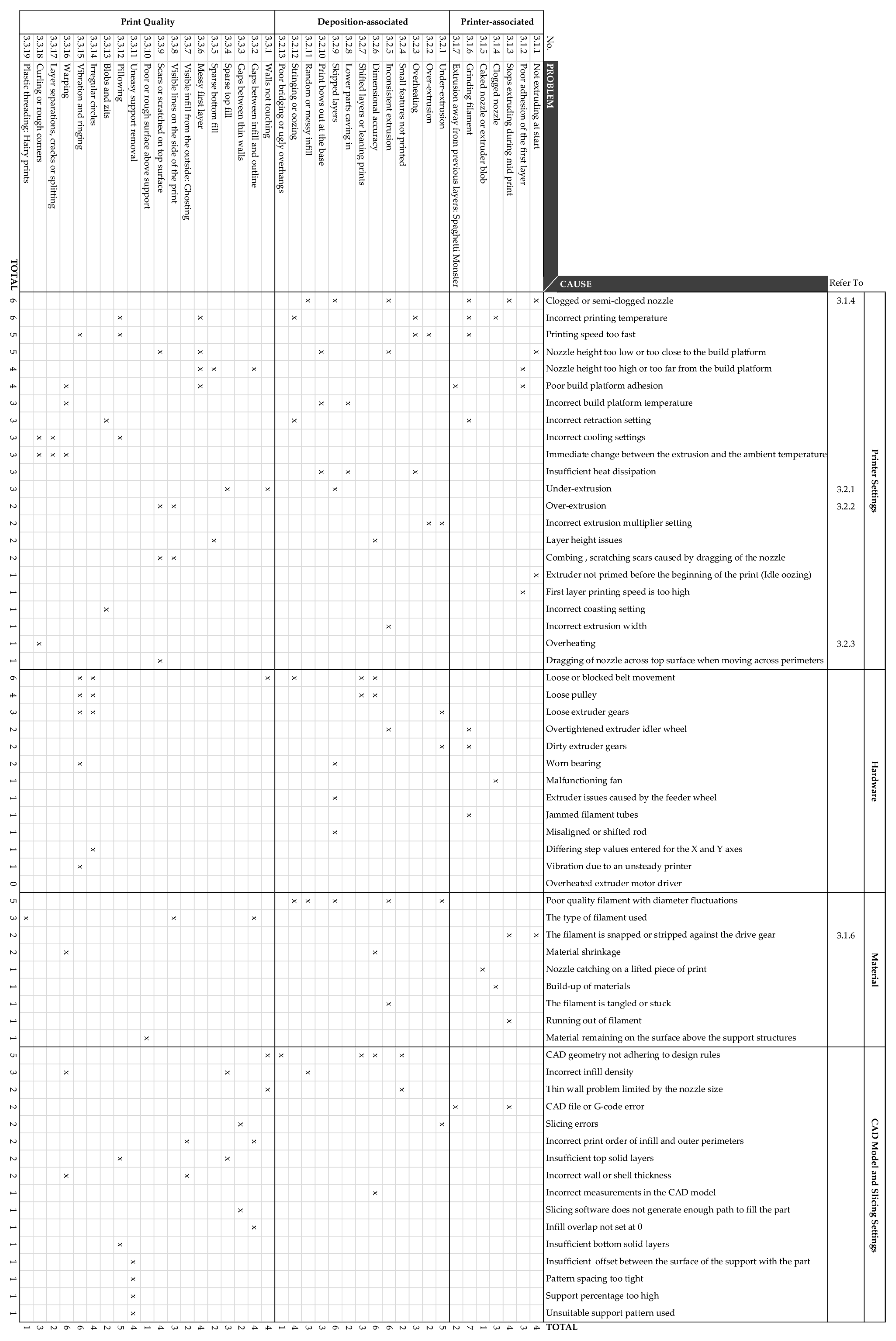
This paper has provided an overview of current issues concerning the use of desktop ME systems. Although it is not machine specific, it covers the most common problems according to printer-associated, deposition-associated and print quality related issues. Nineteen print quality issues were identified, followed by 13 deposition-related issues and 7 printer-related issues. The findings show that the majority of issues are associated with incorrect printer calibration and settings, hardware, material, CAD model and/or slicing settings. Figure 14 presented an overview of ME troubleshooting allowing designers and engineers to straightforwardly determine the possible contributing factors to a particular problem. Although these findings exist in Cartesian printers, similar issues are also commonly encountered in Delta ME machines, Polar ME machines or extruders fitted to robotic arms. It is expected that future work from this study will be developed into an interactive troubleshooting guide to support end-users when working with ME printers.
Author Contributions
Conceptualization, G.H.L.; methodology, G.H.L., E.P.; software, G.H.L.; validation, G.H.L., E.P., J.G.-G., M.M.; data curation, G.H.L.; writing—original draft preparation, G.H.L., E.P.; writing, review and editing, G.H.L., E.P., J.G.-G., M.M.; visualization, G.H.L.; supervision, E.P. All authors have read and agreed to the published version of the manuscript.
Funding
This research received no external funding.
Conflicts of Interest
The authors declare no conflict of interest.
References
- ASTM. BS ISO ASTM 52900:2015 Additive manufacturing General principles Terminology. ASTM 2015, 3, 5. [Google Scholar]
- Redwood, B.; Schöffer, F.; Garret, B. The 3D Printing Handbook; 3D Hubs: Amsterdam, The Netherlands, 2017. [Google Scholar]
- Spoerk, M.; Holzer, C.; Gonzalez-Gutierrez, J. Material extrusion-based additive manufacturing of polypropylene: A review on how to improve dimensional inaccuracy and warpage. J. Appl. Polym. Sci. 2020, 137, 48545. [Google Scholar] [CrossRef]
- Gonzalez-Gutierrez, J.; Cano, S.; Schuschnigg, S.; Kukla, C.; Sapkota, J.; Holzer, C. Additive manufacturing of metallic and ceramic components by the material extrusion of highly-filled polymers: A review and future perspectives. Materials 2018. [Google Scholar] [CrossRef] [PubMed] [Green Version]
- Sakata3D Filaments. HR-PLA 3D870 Natural Super Premium High Resistance. Available online: https://sakata3d.com/gb/pla-hr-870/96-hr-pla-3d870-natural-super-premium-high-resistance.html (accessed on 4 July 2020).
- BlackMagic3D. Conductive Graphene 3D Printing PLA Filament. Available online: https://www.blackmagic3d.com/Conductive-p/grphn-pla.htm (accessed on 4 July 2020).
- Materialise. ABS-ESD7|Fused Deposition Modeling (FDM) at Materialise. Available online: https://www.materialise.com/en/manufacturing/materials/abs-esd7 (accessed on 4 July 2020).
- Materialise. ABSi|Fused Deposition Modeling (FDM) at Materialise. Available online: https://www.materialise.com/en/manufacturing/materials/absi (accessed on 4 July 2020).
- Materialise. PC-ABS|Fused Deposition Modeling (FDM) at Materialise. Available online: https://www.materialise.com/en/manufacturing/materials/pc-abs (accessed on 4 July 2020).
- 3DXTECH. Firewire® Flame Retardant PC-ABS 3D Printing Filament|Jet Black|3D Printing with UL approved V-0 rated flame retardant PC-ABS. Available online: https://www.3dxtech.com/flame-retardant-filaments/firewire-flame-retardant-pc-abs-1kg/ (accessed on 4 July 2020).
- Smart Materials 3D. PETG Magneto Detectable de Smart Materials 3D. Available online: https://www.smartmaterials3d.com/en/petg-magneto-detectable (accessed on 4 July 2020).
- 3DXTECH. AmideXTM Nylon Copolymer 3D Printing Filament. The Workhorse Grade for Engineering Applications—Ease of Printing and Excellent Properties. Available online: https://www.3dxtech.com/engineering-grade-filaments/amidex-nylon-6-66-copolymer/ (accessed on 4 July 2020).
- 3DXTECH. AmideXTM Glass Fiber Reinforced Nylon Copolymer is an Advanced 3D Printing Material. Exceptionally Stiff, Strong, and Impact Resistant. Available online: https://www.3dxtech.com/glass-fiber-reinforced-filaments/amidex-nylon-gf30/ (accessed on 4 July 2020).
- 3DXTECH. Fibretuff® Biomedical 3D Printing Filament|3D Print Bone-Like Anatomical Models to Replace Cadaver Bones. Available online: https://www.3dxtech.com/medical-filaments/fibretuff-biomedical-3d-filament/ (accessed on 4 July 2020).
- Materialise. Ultem 9085|Fused Deposition Modeling (FDM) at Materialise. Available online: https://www.materialise.com/en/manufacturing/materials/ultem-9085 (accessed on 4 July 2020).
- 3DXTECH. 3DXSTAT ESD Safe PEKK Aerospace-Grade 3D Printing Filament|Ultra Performance PEAK Filaments|Made in the USA. Available online: https://www.3dxtech.com/esd-safe-filaments/3dxstat-esd-pekk-a/ (accessed on 4 July 2020).
- 3DXTECH. Kynar PVDF 3D Printing Filament from 3DXTECH|Made in the USA|Free Shipping. Available online: https://www.3dxtech.com/flame-retardant-filaments/fluorx-pvdf/ (accessed on 4 July 2020).
- AON3D. Why Open Filament 3D Printers Matter—AON3D. Available online: https://www.aon3d.com/blog/why-open-filament-3d-printers-matter/ (accessed on 4 July 2020).
- Ultimaker. Ultimaker S5: Reliability at Scale. Available online: https://ultimaker.com/3d-printers/ultimaker-s5 (accessed on 4 July 2020).
- Prusa Research. Original Prusa i3 MK3S—Prusa3D—3D Printers from Josef Průša. Available online: https://www.prusa3d.com/original-prusa-i3-mk3/ (accessed on 4 July 2020).
- LulzBot. LulzBot TAZ Pro Specifications|LulzBot. Available online: https://www.lulzbot.com/store/printers/lulzbot-taz-pro/specifications (accessed on 4 July 2020).
- Tiertime. UP300—Tiertime 3D Printer, ABS 3D Printer, FDM 3D Printer. Available online: https://www.tiertime.com/up300/ (accessed on 4 July 2020).
- Zortax. Zortrax M300 Plus Large Volume Wi-Fi LPD 3D Printer|Zortrax. Available online: https://zortrax.com/3d-printers/m300-plus/ (accessed on 4 July 2020).
- 3Dnatives. 3D Printer: CubePro. Available online: https://www.3dnatives.com/en/3D-compare/imprimante/cubepro (accessed on 4 July 2020).
- Markforged. Mark Two Desktop Carbon Fiber 3D Printer for Manufacturing|Markforged. Available online: https://markforged.com/mark-two/ (accessed on 4 July 2020).
- MakerBot. Method: 3D Printing Technology & Printer Specs|MakerBot. Available online: https://www.makerbot.com/3d-printers/method/tech-specs/ (accessed on 4 July 2020).
- TriLAB. DeltiQ—TRILAB. Available online: https://trilab3d.com/en/deltiq-printer/ (accessed on 4 July 2020).
- Sharebot. The Professional 3D Printer in A3 Format Quality, Precision and Speed on the Biggest Printing Area. Available online: www.sharebot.it (accessed on 4 July 2020).
- German RepRap. x500pro|German RepRap GmbH. Available online: https://www.germanreprap.com/printer/x500pro.aspx (accessed on 4 July 2020).
- Evo-Tech. 3D printer EL-102—EVO-tech 3D-Drucker. Available online: https://evo-tech.eu/en/3d-printer-el-102/ (accessed on 4 July 2020).
- Hage3D. HAGE3D 84L.
- Aniwaa. Apium P220 Review—PEEK-Ready Industrial 3D Printer. Available online: https://www.aniwaa.com/product/3d-printers/apium-p220/ (accessed on 4 July 2020).
- Stratasys. Stratasys F123 Series. Available online: https://www.stratasys.com/3d-printers/f123 (accessed on 4 July 2020).
- XYZPrinting. XYZPrinting PartPro 300xT. Available online: https://pro.xyzprinting.com/en-US/product/FFF/PartPro300_xT (accessed on 4 July 2020).
- Emmett Grames. FDM (3D Printing)—Simply Explained|All3DP. 11 October 2019. Available online: https://all3dp.com/2/fused-deposition-modeling-fdm-3d-printing-simply-explained/?utm_source=push (accessed on 6 May 2020).
- Unger, L.; Scheideler, M.; Meyer, P.; Harland, J.; Görzen, A.; Wortmann, M.; Dreyer, A.; Ehrmann, A. Increasing adhesion of 3D printing on textile fabrics by polymer coating. Tekstilec 2018, 61. [Google Scholar] [CrossRef]
- Spoerk, M.; Gonzalez-Gutierrez, J.; Sapkota, J.; Schuschnigg, S.; Holzer, C. Effect of the printing bed temperature on the adhesion of parts produced by fused filament fabrication. Plast. Rubber Compos. 2018, 47, 17–24. [Google Scholar] [CrossRef]
- Lee, C.Y.; Liu, C.Y. The influence of forced-air cooling on a 3D printed PLA part manufactured by fused filament fabrication. Addit. Manuf. 2019, 25, 196–203. [Google Scholar] [CrossRef]
- Doodaddoes. Twin Cylinders for Tuning Filament Temperature—Repables. Available online: https://repables.com/r/430/ (accessed on 6 May 2020).
- Rigid.Ink. Complete 3D Printing Filament Comparison Guide 2019 [All 17 Compared]. Available online: https://rigid.ink/pages/filament-comparison-guide (accessed on 6 May 2020).
- Fillamentum. Data Sheets—Fillamentum.com. Available online: https://fillamentum.com/pages/data-sheets (accessed on 26 May 2020).
- Spectrum. Spectrum Filaments Catalog (2019). 2019. Available online: https://spectrumfilaments.com/data/include/cms/Spectrum_Catalogue_2019.pdf (accessed on 6 May 2020).
- Privero. Premium POM Filament 1.75mm|Prirevo. Available online: https://www.prirevo.at/produkt/premium-pom-filament-175mm/ (accessed on 26 May 2020).
- Fiberlogy. Fiberlogy Nylon PA12 Technical Data Sheet. Available online: https://fiberlogy.com/wp-content/uploads/2018/10/TDS_PA12CF15.pdf (accessed on 10 May 2020).
- Ultrafuse. Ultrafuse TPC 45D Appricot skin—1.75mm|Flexible 3D Printer Filament. Available online: https://www.ultrafusefff.com/product/ultrafuse-tpc-45d-apricot-skin-1-75mm-500g/ (accessed on 26 May 2020).
- Nippon Gohsei. Brandnew Water Soluble Filament for 3D Printer. Available online: http://www.nippon-gohsei.com/public/downloads/gKHqY/MELFIL%20Brochure%202016%20English.pdf (accessed on 10 May 2020).
- 3D4Makers. Luvocom 3F PEEK 9581 Filament|3D4Makers|3D Printing. Available online: https://www.3d4makers.com/products/luvocom-3f-peek-9581-filament (accessed on 6 May 2020).
- 3D4Makers. PPSU Filament|3D4Makers|3D Printing. Available online: https://www.3d4makers.com/products/ppsu-filament (accessed on 6 May 2020).
- 3D4Makers. PEI Ultem 1010 Filament|3D4Makers|3D Printing. Available online: https://www.3d4makers.com/products/pei-filament (accessed on 6 May 2020).
- 3DPrinting. PVDF Filament Printing Guide—3D Printing. 19 March 2019. Available online: https://3dprinting.com/filament/pvdf-filament-printing-guide/ (accessed on 6 May 2020).
- 3D4Makers. PEKK Filament|3D4Makers|Luvocom® 3F 50082 Serie. Available online: https://www.3d4makers.com/products/luvocom-3f-pekk-50082-filament (accessed on 26 May 2020).
- Fernandez-Vicente, M.; Calle, W.; Ferrandiz, S.; Conejero, A. Effect of Infill Parameters on Tensile Mechanical Behavior in Desktop 3D Printing. 3D Print. Addit. Manuf. 2016, 3, 183–192. [Google Scholar] [CrossRef]
- 3DMatter. How Do Layer Height & Infill Settings Impact 3D Print Strength? 3D Matter. Available online: https://my3dmatter.com/influence-infill-layer-height-pattern/ (accessed on 26 May 2020).
- Petersmann, S.; Spoerk, M.; Huber, P.; Lang, M.; Pinter, G.; Arbeiter, F. Impact Optimization of 3D-Printed Poly(methyl methacrylate) for Cranial Implants. Macromol. Mater. Eng. 2019, 304, 1900263. [Google Scholar] [CrossRef]
- Ed Tyson. How to Print Overhangs, Bridges and Beyond the 45° Rule + No Supports. Available online: https://rigid.ink/blogs/news/how-to-print-overhangs-bridges-and-exceeding-the-45-rule (accessed on 6 May 2020).
- Ultimaker. How to Level the Ultimaker 3 Build Plate—Ultimaker Support. Available online: https://support.ultimaker.com/hc/en-us/articles/360011471740 (accessed on 6 May 2020).
- Treitler, M. Additive Fertigung Mit Fasergefüllten Compounds Für Technische Anwendungen. Bachelor Thesis, Montanuniversitaet Leoben, Leoben, Austria, September 2018. [Google Scholar]
- Raney, K.; Lani, E.; Kalla, D.K. Experimental characterization of the tensile strength of ABS parts manufactured by fused deposition modeling process. Mater. Today Proc. 2017, 4, 7956–7961. [Google Scholar] [CrossRef]
- Ben Hudson. How to Design Parts for FDM 3D Printing|3D Hubs. Available online: https://www.3dhubs.com/knowledge-base/how-design-parts-fdm-3d-printing/?action#build-direction (accessed on 6 May 2020).
- 3DHubs. What is 3D Printing? The Definitive Guide|3D Hubs. 2020. Available online: https://www.3dhubs.com/guides/3d-printing/ (accessed on 6 May 2020).
- Jennings, A. Troubleshooting Guide to Common 3D Printing Problems|All3DP. 2020. Available online: https://all3dp.com/1/common-3d-printing-problems-troubleshooting-3d-printer-issues/ (accessed on 6 May 2020).
- Chakravorty, D. 3D Printing Support Structures—The Ultimate Guide|All3DP. 3 January 2020. Available online: https://all3dp.com/1/3d-printing-support-structures/ (accessed on 6 May 2020).
- Chvalina, T. How to Fix the Most Common 3D Printing Errors—Prusa Printers. 27 April 2018. Available online: https://blog.prusaprinters.org/how-to-fix-the-most-common-3d-printing-errors/ (accessed on 6 May 2020).
- Chvalina, T. 7 Problems Affecting the Quality of Your 3D Prints—Prusa Printers. 10 August 2018. Available online: https://blog.prusaprinters.org/7-problems-affecting-quality-of-3d-prints/ (accessed on 6 May 2020).
- 3DVerkstan. A Visual Ultimaker Troubleshooting Guide—3DVerkstan Knowledge Base. Available online: https://support.3dverkstan.se/article/23-a-visual-ultimaker-troubleshooting-guide (accessed on 6 May 2020).
- Prusa3D. How to Improve the Quality of Your 3D Prints on the Original Prusa i3 MK3?—YouTube. 2018. Available online: https://www.youtube.com/watch?v=Lsa-PXAXdKY&t=52s (accessed on 6 May 2020).
- Prusa3D. 3D Printing Handbook. User Manual for 3D Printers: Original Prusa i3 MK3 Kit, Original Prusa i3 MK3. 2018. Available online: www.prusa3d.de/treiber/ (accessed on 6 May 2020).
- Spoerk, M.; Gonzalez-Gutierrez, J.; Lichal, C.; Cajner, H.; Berger, G.R.; Schuschnigg, S.; Cardon, L.; Holzer, C. Optimisation of the Adhesion of Polypropylene-Based Materials during Extrusion-Based Additive Manufacturing. Polymers 2018, 10, 490. [Google Scholar] [CrossRef] [PubMed] [Green Version]
- PPPrint. PPPrint|Polypropylen Filamente Für den 3D Druck. Available online: https://www.ppprint.de/?lang=en (accessed on 26 May 2020).
- Issal, A. 3D Printer Clogged Nozzle: How to Perform a Cold Pull|All3DP. 2019. Available online: https://all3dp.com/2/3d-printer-clogged-nozzle-how-to-perform-a-cold-atomic-pull/ (accessed on 11 May 2020).
- 3DHubs. Fan Not Turning On—3D Printing/3D Printers—Talk Manufacturing|3D Hubs. 2017. Available online: https://www.3dhubs.com/talk/t/fan-not-turning-on/11047 (accessed on 11 May 2020).
- Stříteský, O. Does Your Newly Assembled Original Prusa i3 MK3 Print the Best it Can?—Prusa Printers. Available online: https://blog.prusaprinters.org/does-your-freshly-assembled-original-prusa-i3-mk3-print-as-the-best-it-can/ (accessed on 6 May 2020).
- Godec, D.; Cano, S.; Holzer, C.; Gonzalez-Gutierrez, J. Optimization of the 3D Printing Parameters for Tensile Properties of Specimens Produced by Fused Filament Fabrication of 17-4PH Stainless Steel. Materials 2020, 13, 774. [Google Scholar] [CrossRef] [PubMed] [Green Version]
- Slic3r Manual. Slic3r Manual—Print Settings. Available online: https://manual.slic3r.org/expert-mode/print-settings#infill-patterns (accessed on 6 May 2020).
- Frank. (681) Retraction Calibration—YouTube. Available online: https://www.youtube.com/watch?v=KwcKX3o3kCU (accessed on 12 May 2020).
- Simplify3D. Stringing or Oozing. Available online: https://www.simplify3d.com/support/print-quality-troubleshooting/stringing-or-oozing/ (accessed on 12 May 2020).
- Mikolas Zuza. 5 Things You Might not Know about Your Original Prusa i3 MK3—Prusa Printers. 2 February 2018. Available online: https://blog.prusaprinters.org/5-things-might-not-know-original-prusa-i3-mk3/ (accessed on 12 May 2020).
- Simplify3D. Blobs and Zits. Available online: https://www.simplify3d.com/support/print-quality-troubleshooting/blobs-and-zits/ (accessed on 13 May 2020).
- Slic3r Manual. Slic3r Manual—Fighting Ooze. Available online: https://manual.slic3r.org/expert-mode/fighting-ooze (accessed on 13 May 2020).
Figure 1.
The material extrusion (ME) process.

Figure 2.
Explanation of the print layers from the ME process.

Figure 3.
Types of infill pattern from the Slic3r PE software.

Figure 4.
Definition of raft, brim and skirt.

Figure 5.
Printing of a PA12 part with (A) a skirt leads to detachment from the build platform; (B) printing with a brim leads to completion of the printing job [57].
Figure 5.
Printing of a PA12 part with (A) a skirt leads to detachment from the build platform; (B) printing with a brim leads to completion of the printing job [57].

Figure 6.
The optimum nozzle height and first layer width.

Figure 7.
Grinding or stripping of filament.

Figure 8.
Spaghetti monster.

Figure 9.
Inconsistent extrusion of filament.

Figure 10.
Shifted layers.

Figure 11.
Walls not touching.

Figure 12.
Visible infill from the outside.

Figure 13.
Blobs and zits marks on outer shell surface of the part.

Figure 14.
The most common problems of ME processes and their causes.


Table 1.
Examples of ME thermoplastic materials and their targeted sector and specific applications.
Table 1.
Examples of ME thermoplastic materials and their targeted sector and specific applications.
| Material | Sector | Specific Applications | Advantages | Ref. |
|---|---|---|---|---|
| Sakata 3D HR-PLA 3D870 | General | Final parts | Annealed PLA print with ABS-like resistance | [5] |
| BlackMagic 3D Conductive | Electronics | Electrical Circuits | Electrically conductive | [6] |
| Materialise ABS-ESD7 | Electronic circuits | Electrostatic dissipation | High resistance and electrostatic dissipation | [7] |
| Materialise ABSi | Motorsports and medical | Final parts | Allows light transmission and flow control | [8] |
| Materialise PC-ABS | General | Final parts | Greater physical and thermal resistance than ABS | [9] |
| FIREWIRE® Flame Retardant PC/ABS | Transports | Final parts | Flame retardant | [10] |
| Smartfill PETG MDT | Food industry | Magnetically detection | Magnetic detection and dimensional stability | [11] |
| AMIDEX™ Nylon 6/66 Copolymer | General | Final parts | Engineering specifications | [12] |
| AMIDEX™ 30% Glass Fiber Reinforced Nylon (PA6) | High performance Engineering | Final parts | Fiberglass reinforced Nylon | [13] |
| FIBRETUFF® Biomedical 3D Filament | Medicine | Medical prototypes, training | Printing medical, dental, and veterinary bone models | [14] |
| Materialise Ultem 9085 | Aerospace and automotive | Final parts | High strength-to-weight ratio | [15] |
| 3DXSTAT™ ESD PEKK-A | Aeronautic | Final parts | Heat dissipation and static electricity | [16] |
| FluorX™ PVDF 3D Filament | High performance Engineering | Final parts | High chemical and thermal resistance | [17] |
Table 2.
Examples of desktop, professional and industrial ME equipment and their capabilities.
| Manufacturer | Model | Maximum Build Volume (X/Y/Z) mm | Print Object Accuracy X-, Y, Z (μm) | Open System (Yes/No) | Temperature Range (°C) for Open System/Materials for Closed System | Ref. |
|---|---|---|---|---|---|---|
| Ultimaker BV | S5 | 330 × 240 × 300 | 6.9, 6.9, 2.5 | Yes | Print head: 180–280 Chamber: No Print bed: up to 140 | [19] |
| Prusa Research a.s | I3 MK3/S | 250 × 210 × 200 | 10, 10, 5 | Yes | Print head: up to 300 Chamber: No Print bed: up to 120 | [20] |
| Fargo Additive Manufacturing Equipment 3D | LulzBot TAZ Pro | 280 × 280 × 285 | 500, 500, 500 | Yes | Print head: up to 290 Chamber: No Print bed: up to 120 | [21] |
| Beijing Tiertime Technology Co. Ltd. | UP300 | 203 × 254 × 224 | 2, 2, 0.5 | Yes | Print head: up to 299 Chamber: No Print bed: up to 100 | [22] |
| Zortrax S.A | M300 Plus | 300 × 300 × 300 | 90–290 | Yes | Print head: up to 290 Chamber: No Print bed: up to 105 | [23] |
| 3D Systems, Inc. | CubePro | 578 × 578 × 591 | 200, 200, 100 | Yes | Print head: up to 280 Chamber: No Print bed: N/A | [24] |
| Markforged, Inc. | Mark Two | 320 × 132 × 154 | 100, 100, 100 | No | Polymer: Onyx, Nylon White Continuous fibre: Carbon fibre, fiberglass, Kevlar®, HSHT fiberglass | [25] |
| MakerBot Industries, LLC | Method | 190 × 190 × 196 | 200, 200, 200 | No | ABS, ASA, PLA, Tough, PVA, SR-30, Nylon, PETG | [26] |
| TriLAB Group s.r.o | DeltiQ M | 180 × 200 | 250, 250, 50 | Yes | Print head: up to 400 Chamber: No Print bed: up to 105 | [27] |
| Sharebot srl | Q | 297 × 420 × 300 | 50, 40, 40 | Yes | Print head: up to 260 Chamber: No Print bed: up to 100 | [28] |
| German RepRap GmbH | x500pro | 500 × 400 × 450 | 20, 50, 20 | Yes | Print head: up to 400 Chamber: 80 Print bed: up to 150 | [29] |
| EVO-tech GmbH | EL-102 | 500 × 400 × 510 | 20, 20, 20 | Yes | Print head: up to 400 Chamber: 100 Print bed: up to 200 | [30] |
| HAGE3D GmbH | 84L | 400 × 600 × 350 | 100, 100, 100 | Yes | Print head: up to 450 Chamber: 85 Print bed: up to 160 | [31] |
| Apium Additive Technologies GmbH | Apium P220 | 205 × 155 × 150 | 12.5, 12.5, 50 | Yes | Print head: up to 540 Chamber: up to 180 Print bed: up to 160 | [32] |
| Stratasys | F370 | 355 × 254 × 355 | 20,20, 127 | No | PLA, ABS-M30, ASA, PC-ABS, TPU 92A, QSR Support material | [33] |
| XYZPRINTING Inc. | PartPro300 xT | 295 × 300 × 300 | 12.5, 12.5, 20 | Yes | Print head: up to 350 Chamber: 70 Print bed: up to 100 | [34] |
Table 3.
Material temperature comparison.
| Material Type | Filament Material | Nozzle Temperature (°C) | Build Platform Temperature (°C) | Fan Power (%) | Heated Chamber | Ref. |
|---|---|---|---|---|---|---|
| Commodity | ABS | 230–250 | 90–95 | 0 | N/A | [40] |
| HIPS | 230–250 | 90–105 | N/A | N/A | [41] | |
| PP | 235–255 | 100 | 0 | Yes | [42] | |
| PLA | 180–210 | Room–45 | 100 | N/A | [40] | |
| PLA Plus+ | 220–240 | 45 | 100 | N/A | [40] | |
| Engineering | PETG | 220–245 | 70–80 | As needed | N/A | [40] |
| PETG HT100 | 250–280 | 100–110 | 0 | Yes | [42] | |
| ASA | 230–250 | 90–100 | 10 | [40] | ||
| PMMA | 245–255 | 100 | 10–20 | [40] | ||
| PA6 Low warp | 250–270 | 85–100 | 0 | No | [42] | |
| PA6 Neat | 240–270 | 80–100 | 0 | Yes | [42] | |
| Nylon | 255–275 | 100–110 | 0 | [40] | ||
| Nylon Plus | 255–275 | 100–110 | 0 | [40] | ||
| PC | 300 and above | 100 and above | 0 | [40] | ||
| POM | 190–205 | 120 | N/A | N/A | [43] | |
| PA12 | 255–270 | 100 | N/A | N/A | [44] | |
| Composites | PLA Carbon | 185–215 | Room–45 | As needed | N/A | [42] |
| PLA Wood | 190–210 | Room–45 | As needed | N/A | [42] | |
| PET CF15 | 220–240 | 40–60 | As needed | No | [42] | |
| PA6 CF15 | 235–260 | 80–100 | 0 | No | [42] | |
| PA6 GK10 | 235–260 | 80–100 | 0 | Yes | [42] | |
| Carbonyte | 260–275 | 110–115 | 0 | [40] | ||
| Flexible | Flexible PLA | 240–250 | 30–60 | 100 | [40] | |
| PETG FX 120 | 240–260 | 80 | As needed | No | [42] | |
| TPU | 210–240 | 20–70 | As needed | [40] | ||
| TPC | 230–250 | 0–30 | N/A | N/A | [45] | |
| Support | HIPS | 230–240 | 95–105 | 0 | [40] | |
| PVA | 190–210 | None–45 | As needed | [40] | ||
| BVOH | 190–210 | 80–100 | N/A | N/A | [46] | |
| High performance | PEEK | 360–400 | 120 | 0 | Yes | [47] |
| PPSU | 360–400 | 140 or more | 0 | Yes | [48] | |
| PEI | 355–390 | 120–160 | 0 | Yes | [49] | |
| PVDF | 230–240 | 75–90 | 0 | No | [50] | |
| PEKK | 320–360 | 110–140 | N/A | N/A | [51] |
Table 4.
Build direction and its effects on part weakness [2].
Table 4.
Build direction and its effects on part weakness [2].
| Weaker Resultant Part | Stronger Resultant Part |
|---|---|
 |  |
 |  |
Table 5.
Strategies to avoid support structure.
| Support Needed | Support Not Needed |
|---|---|
 |  |
 |  |
 |  |
 |  |
 |  |


Table 7.
List of Common Problems.
| 3.1 Printer-Associated | 3.2 Deposition-Associated | 3.3 Print Quality |
|---|---|---|
| 3.1.1 Not extruding at start 3.1.2 Poor adhesion of the first layer 3.1.3 Stops extruding during mid print 3.1.4 Clogged nozzle 3.1.5 Caked nozzle or extruder blob 3.1.6 Grinding filament 3.1.7 Extrusion away from previous layers: Spaghetti Monster | 3.2.1 Under-extrusion 3.2.2 Over-extrusion 3.2.3 Overheating 3.2.4 Small features not printed 3.2.5 Inconsistent extrusion 3.2.6 Dimensional accuracy 3.2.7 Shifted layers or leaning prints 3.2.8 Lower parts caving in 3.2.9 Skipped layers 3.2.10 Print bows out at the base 3.2.11 Random or messy infill 3.2.12 Stringing or oozing 3.2.13 Poor bridging or ugly overhangs | 3.3.1 Walls not touching 3.3.2 Gaps between infill and outline 3.3.3 Gaps between thin walls 3.3.4 Sparse top fill 3.3.5 Sparse bottom fill 3.3.6 Messy first layer 3.3.7 Visible infill from the outside: Ghosting 3.3.8 Visible lines on the side of the print 3.3.9 Scars or scratched on top surface 3.3.10 Poor or rough surface above support 3.3.11 Uneasy support removal 3.3.12 Pillowing 3.3.13 Blobs and zits 3.3.14 Irregular circles 3.3.15 Vibration and ringing 3.3.16 Warping 3.3.17 Layer separations, cracks or splitting 3.3.18 Curling or rough corners 3.3.19 Plastic threading: Hairy prints |
© 2020 by the authors. Licensee MDPI, Basel, Switzerland. This article is an open access article distributed under the terms and conditions of the Creative Commons Attribution (CC BY) license (http://creativecommons.org/licenses/by/4.0/).
Share and Cite
MDPI and ACS Style
Hsiang Loh, G.; Pei, E.; Gonzalez-Gutierrez, J.; Monzón, M. An Overview of Material Extrusion Troubleshooting. Appl. Sci. 2020, 10, 4776. https://doi.org/10.3390/app10144776
AMA Style
Hsiang Loh G, Pei E, Gonzalez-Gutierrez J, Monzón M. An Overview of Material Extrusion Troubleshooting. Applied Sciences. 2020; 10(14):4776. https://doi.org/10.3390/app10144776
Chicago/Turabian StyleHsiang Loh, Giselle, Eujin Pei, Joamin Gonzalez-Gutierrez, and Mario Monzón. 2020. "An Overview of Material Extrusion Troubleshooting" Applied Sciences 10, no. 14: 4776. https://doi.org/10.3390/app10144776
Note that from the first issue of 2016, this journal uses article numbers instead of page numbers. See further details here.