Principles and Characteristics of Different EDM Processes in Machining Tool and Die Steels
by
 , , , and
Jaber E. Abu Qudeiri
1,* ,
,
Aiman Zaiout
1,
Abdel-Hamid I. Mourad
1,
Mustufa Haider Abidi
2 and
and
Ahmed Elkaseer
3,4 1
Mechanical Engineering Department, College of Engineering, United Arab Emirate University, Al Ain 15551, UAE
2
Raytheon Chair for Systems Engineering (RCSE), Advanced Manufacturing Institute, King Saud University, Riyadh 11421, Saudi Arabia
3
Department of Production Engineering and Mechanical Design, Faculty of Engineering, Port Said University, Port Said 42526, Egypt
4
Institute for Automation and Applied Informatics, Karlsruhe Institute of Technology, 76344 Karlsruhe, Germany
*
Author to whom correspondence should be addressed.
Appl. Sci. 2020, 10(6), 2082; https://doi.org/10.3390/app10062082
Submission received: 29 January 2020
/
Revised: 28 February 2020
/
Accepted: 10 March 2020
/
Published: 19 March 2020
(This article belongs to the Section Mechanical Engineering)
Abstract
:Electric discharge machining (EDM) is one of the most efficient manufacturing technologies used in highly accurate processing of all electrically conductive materials irrespective of their mechanical properties. It is a non-contact thermal energy process applied to a wide range of applications, such as in the aerospace, automotive, tools, molds and dies, and surgical implements, especially for the hard-to-cut materials with simple or complex shapes and geometries. Applications to molds, tools, and dies are among the large-scale initial applications of this process. Machining these items is especially difficult as they are made of hard-to-machine materials, they have very complex shapes of high accuracy, and their surface characteristics are sensitive to machining conditions. The review of this kind with an emphasis on tool and die materials is extremely useful to relevant professions, practitioners, and researchers. This review provides an overview of the studies related to EDM with regard to selection of the process, material, and operating parameters, the effect on responses, various process variants, and new techniques adopted to enhance process performance. This paper reviews research studies on the EDM of different grades of tool steel materials. This article (i) pans out the reported literature in a modular manner with a focus on experimental and theoretical studies aimed at improving process performance, including material removal rate, surface quality, and tool wear rate, among others, (ii) examines evaluation models and techniques used to determine process conditions, and (iii) discusses the developments in EDM and outlines the trends for future research. The conclusion section of the article carves out precise highlights and gaps from each section, thus making the article easy to navigate and extremely useful to the related research community.
1. Introduction
In recent years, rapid developments in aerospace, medical instruments, transportation, and many other industrial sectors increased the need for new materials with favorable characteristics. In addition to unique characteristics, most modern materials need special manufacturing processes to enable them to be machined with ease [1,2]. Most of these materials are usually difficult to cut by conventional manufacturing processes [3,4,5,6,7]. The unique characteristics of these hard-to-cut materials increase their applications, which further drive manufacturers to explore new machining processes with reasonable cost and high precision [8,9].
Tool steels and other tool materials (e.g., carbides) are such widely used hard-to-cut materials because of their high hardness and abrasion wear resistance, in addition to their ability to withstand high load and to operate in rapidly changing temperatures [6]. Tool steels have a wide range of applications, including stamping and metal-working dies, cutting tools, hammers, and machine parts [10]. Applications of these tools in the manufacturing sector is very large; thus, there exists huge machining requirements of tools, tooling, dies, and molds [11]. Before being put to use, these steels are subjected to heat treatment to meet the required properties for specific application [12,13]. In addition to iron and carbon, tool steels have in them other elements (e.g., Cr, W, V, Mo, etc.) to increase their strength, hardness, hot strength and hot hardness, and wear resistance. Although these steels can be machined by conventional methods, they come with serious concerns with regard to very poor tool life and part accuracy [14].
Electric discharge machining (EDM) is one of the most advanced manufacturing methods used to successfully machine conductive hard-to-cut materials [8,15,16,17,18,19]. EDM is the process of choice to machine hard-to-cut materials widely used in modern industries to facilitate accurate machining [20,21,22,23,24,25], complex shape machining, and better surface integrity. The process is utilized to machine electrically conductive materials by applying repetitive sparks between electrode and workpiece. Unlike in mechanical machining, no deforming force is required between the electrode and the workpiece, and the machining takes place without actual contact between them [23,26,27,28]. There are a large number of variants of the EDM process such as sinking EDM, wire EDM, micro-EDM, powder-mixed EDM, and dry EDM; all of these possess work on the same mechanism of material removal. Developments of variants make the process more versatile and suitable for relatively big and micro-scale machining areas.
Several review papers related to EDM were published in recent years such as references [29,30,31,32,33,34,35], among others. Furthermore, some other articles presented a discussion of specific objectives; for example, Barenji et al. [36] developed a model for prediction of material removal rate (MRR) and tool wear rate (TWR) for the EDM of AISI D6 tool steel. They reported that higher values of pulse-on time resulted in higher MRR and lesser TWR. Long et al. [37] used powder-mixed EDM for machining die steels. Titanium powder was used for mixing, and surface quality was analyzed. It was revealed that the quality of surface layer was improved at optimal parameters. Shabgard et al. [38] studied the effects of the key input variables of wire EDM of ASP30 tool steel. The output responses under consideration were MRR and surface roughness. The results revealed that an increase in spraying pressure of dielectric fluid led to a higher MRR and surface roughness. EDM of AISI M42 high-speed tool steel alloy was conducted to study the effect of major input parameters on MRR. It was revealed that tool polarity was the most influential factor and, at negative polarity, maximum MRR was achieved. P20 tool steel was machined using wire EDM, and pulse-on time, pulse-off time, peak current, and spark gap voltage were varied. The output responses under study were kerf width and MRR. The best combination of parameters was reported to achieve maximum MRR [39]. Sharma and Sinha [40] applied rotary-EDM to machine AISI D2 tool steel using a copper electrode. MRR, TWR, and machining rate were studied by varying input parameters (peak current, voltage, duty cycle, and electrode rotation speed). Bahgat et al. [41] conducted experiments to study the effect of major input variables on MRR, electrode wear ratio, and surface roughness while machining H13 die steel. It was reported that higher MRR and lower electrode wear rate were achieved using a copper electrode, whereas lower surface roughness was attained with a brass electrode. Gopal et al. [42] compared the performance of unprocessed and equal channel angular pressing (ECAP)-processed copper electrode while machining AISI H13 tool steel using EDM. It was reported that the triple-ECAP-passed electrode gave better machining quality.
Despite many existing review papers, to the best of authors’ knowledge, there is no study that reviewed the EDM process specifically for tool and die steels. Since tool and die steels have usage in a wide range of applications and they are difficult to cut with the conventional manufacturing processes, non-conventional processes such as EDM are becoming prevalent for their machining. Generally, one of the largest uses of the EDM process is in tool-, die-, and mold-making. All these industries mostly use various kinds of tool steels. EDM remains one of the most popular processes used for their fabrication. Therefore, it is important to have in-depth knowledge of this subject and, hence, the aim of this research paper is to provide comprehensive information and details of this process. It is important for review articles such as this one to bring out the intricacies of processes, parameter–response co-relations, and critical analysis of their response to better utilize them. This will prove to be of great use to understand failures, as well as in-service performance issues, of tools and tooling. The present article aims to provide an overview of the significant contributions of EDM to machining of tool steels. This paper gives the state of the art on current research studies conducted in all EDM variants for machining different grades of tool materials. The paper begins with a brief introduction of EDM and its variants, and then introduces its working principle. It further discusses the EDM process parameters and its performance measures. The main text of this article provides a meticulous review on major areas of EDM research using different grades of tool materials. The last section of the paper draws conclusions, and trends of the reviewed bodies of research are subsequently drawn. Figure 1 shows the EDM processes and their main process parameters and output (performance) measures.
2. EDM Process Details
2.1. Working Principle of EDM
The EDM process was invented in the 1940s [23]. The process uses thermoelectric energy to erode workpieces due to rapidly recurring electrical discharges (sparks) between the non-contact electrode and workpiece [43,44,45,46]. The discharge current flows from between the electrode and workpiece through the small distance between them, called a “gap”, which is filled with dielectric fluid. Dielectric fluid also simultaneously flushes the gap continuously during the machining and carries away debris (particle erosion produced as a result of machining) and restores the sparking condition in the gap. A proper gap is carefully selected to a value such that it generates surge current by breaking down the dielectric film under a set voltage. There are no cutting forces used between the electrode and the workpiece as there is no contact between them. This condition eliminates vibration and problems arising due to machining forces [47,48].
2.2. EDM Process Parameters
The EDM process parameters which drive this process are divided into two types, namely, electrical and non-electrical parameters. The major electrical parameters are discharge voltage, peak current, pulse duration and interval (pulse-on and pulse-off times), electrode gap, polarity, and pulse wave form. Important non-electrical parameters include flushing of the dielectric fluid, workpiece rotation, electrode rotation, etc. These parameters are discussed below.
The discharge or machining voltage is the average voltage across the spark gap during machining. The discharge voltage directly influences the regulation of the size spark gap and overcut [49,50,51,52]. Normally, electrode and workpiece materials of high electrical conductivity use low voltage. In contrast, higher voltage is considered with materials of low conductivity. This parameter has a direct effect on the material removal rate (MRR), tool wear rate (TWR), and machining accuracy [53,54,55,56,57]. An increase in current increases MRR and TWR and adversely affects the accuracy. These characteristics of the parameter current and its responses opened the door for electrodes of high wear resistance that can be used in high-current conditions [47].
The pulse-on time is the time during which the discharge is applied. The amount of energy generated during pulse-on time has a direct influence on the MRR [54,55,56,57,58,59,60]. Accordingly, increasing the discharge energy by applying longer pulse-on time also increases the MRR [61]. The pulse-off time is the time during which there is no discharge. During this time, the debris as a result of sparking and erosion is flushed out of the gap between the workpiece and the electrode [62]. Flushing improves the ionization conditions and avoids the formation of an insulating layer; thus, proper selection of pulse-off time provides stable machining [63,64,65]. A shorter period of this time increases MRR as long as enough flushing of debris takes place. Otherwise, it may result in unsuitable conditions during the next pulse-on time period [66]. Furthermore, a pulse wave has many forms such as rectangular and trapezoidal waves or even a composite geometric form. It is demonstrated in the literature that, among standard forms, the trapezoidal wave form generator minimizes the electrode wear [67]. Recently, other generators were developed such as a typical one which initially facilitates the main pulse by producing a high-voltage pulse with a low current of narrower duration before the main pulse [63].
The polarity in EDM depends on many factors, including electrode and workpiece materials, current density, and pulse length [68,69]. Either the electrode or the workpiece has a positive charge polarity and the other has a negative charge polarity. Negative electrode polarity is recommended for high-precision machining when the MRR is high. In the wire EDM process, the electrode “wire” usually has a negative polarity to keep machining rate high, and, since the wire wear keeps on moving continuously during arcing, its wear rate is less. The electrode and workpiece are located at a small predetermined distance called the “discharge gap” which is controlled by the discharge gap servo [70]. A discharge gap on the order of 0.005 mm and 0.1 mm is usually maintained. Finishing or high-precision machining requires a relatively low voltage in the gap on the order of 50 V and 300 V, as too high a voltage reduces machining precision.
Non-electrical parameters include flushing of the dielectric fluid, workpiece rotation, and electrode rotation. The function of the dielectric fluid is to provide insulation against premature discharging, reduce the temperature during machining, and clean away the debris from the machining area [71]. Good dielectric fluids should have characteristics such as high dielectric strength, flushing ability, fast recovery after breakdown, etc. [72]. In the case of a sinker type EDM, hydrocarbon- and silicon-based dielectric oil and kerosene are used after raising the flash point. Meanwhile, de-ionized water and oil are used in wire EDM. Moreover, some sinker EDMs also use de-ionized water in high-precision machining, such as in fine hole drilling. Many studies were conducted recently to explore oil-based synthetics to avoid harmful effects on workers and the environment [73,74,75]. Importantly, the dielectric type and flushing method influence MRR, TWR, and surface roughness (SR) [76,77,78]. The dielectric flushing conditions can be improved with workpiece and electrode rotation [79,80]. This improvement in flushing caused by electrode rotation achieves better SR and higher MRR [81,82,83] and minimizes the density of cracks on the surface and recast layer [76]. The effect of the EDM process parameters on the response parameters are difficult to explain because of the stochastic nature of the discharge mechanism [84]. Several researchers performed studies related to EDM processes and explored the influence of process parameters on the performance measures [21,54,58,85,86].
2.3. Performance Measures/Parameters
Performance parameters are the factors that measure performance of the EDM process. There are numerous parameters, but the main performance measure parameters are MRR, TWR, and surface quality. The MRR is the erosion rate of workpiece surface; it also defines the measure of the machining speed. A large number of studies were performed with a focus on ways and techniques that result in an improvement in MRR [87,88,89,90,91]. On the other hand, TWR is a performance measure for the erosion rate of the tool electrode. This parameter has a direct influence on the geometry and accuracy of the machined cavity due to a continued change in the electrode profile during the machining process. Apart from the accuracy and geometry of the part being machined, it also affects the life of the tool. A focus on reducing TWR is extremely important because wear of the electrode affects the electrode profile and leads to lower accuracy [85,92,93]. The surface integrity is another important response which is representative of machined surface quality or conditions. The surface quality is a composite characteristic with components such as SR, extent of the heat-affected zone (HAZ), recast layer thickness, and micro-crack density. Many research studies were introduced to explore utilization of the EDM process in surface treatment, and they reported the surface effectiveness caused by the process [94].
2.4. Various EDM Process Variants
2.4.1. Sinking EDM or Sinker Type EDM
The sinker type EDM set-up is schematically shown in Figure 2. In the sinking type EDM process, two machining systems are applied. In the first system, a controlled electrical spark is repeated until the electrode shape is replicated over the workpiece surface. In the second system, the electrode moves in three-dimensional (3D) space to machine a complex 3D shape on work surface. A hybrid of the two cutting systems, however, is possible but remains to be reported. The sinking EDM process has a characteristic sharp rise in the temperature (i.e., 8000 to 12,000 °C) of the machining area. EDM machines have a unit control system that controls and monitors the machining variables and shows the process execution sequence. A wide range of electrode materials are used, the choice of which also depends on the workpiece materials; copper and copper-doped metals with graphite, among others, are widely used as the electrode materials in the sinking EDM process. Due to electrode wear, the electrode is often re-shaped to execute the finishing operations. Normally, this process uses a hydrocarbon dielectric fluid because of its positive effect on the SR and electrode wear rate (EWR).
2.4.2. Wire EDM
In wire EDM, a continuously moving metallic wire of small diameter follows a well-defined path to cut a workpiece. Discrete sparks between the wire and the workpiece cause erosion in the machining area. As in sinker type EDM, the wire and workpiece do not have any contact during machining in wire EDM. Furthermore, both of them should be immersed in dielectric fluid. The wire used in this process is usually thin in diameter, as small as 0.1 mm or so; it is generally made of copper, brass, coated steel materials, or even metals like molybdenum. A high peak current with a short duration time is applied in this process. The machine control unit enables the necessary movement through a computer numerical control (CNC) system to cut complicated shapes [95]; it contains a dedicated microprocessor to maintain the gap within a suitable range (25–50 µm). In addition, the unit controls the speed of the wire through the workpiece, which produces surfaces with very high accuracy. De-ionized water is a common dielectric fluid used in this process. The wire EDM process has a wide range of applications, such as in die making, medicine, electronics, and the automotive industry [50]. Figure 3 shows a schematic diagram of wire EDM.
2.4.3. Micro-EDM
Micro-EDM follows the same principle as sinking EDM and wire EDM; however, it removes material at a micro-scale for components smaller than 100 μm. This process cuts workpieces of micro-scale, including micro-holes, micro-shafts, and any 3D micro-cavities [96]. The MRR will be in nanometers because the machined part is at the micro level. Characteristically, micro-EDM works on a very small pulse energy and requires voltage and current several orders lower than those used in normal EDM processes. This process can produce hole or shaft diameters on the order of 5 µm [47]. EDM in the micro-scale is available in four configurations, namely, die sinking micro-EDM, micro-wire EDM, micro-EDM drilling, and micro-EDM milling. In micro-wire EDM, a wire with a diameter less than 20 μm is used [24].
2.4.4. Powder-Mixed EDM
As the name implies, powder of suitable material, such as nickel or even ceramics, is mixed with dielectric fluid. The presence of powder makes the process mechanism totally different from the conventional EDM process [97]. In fact, powder particles fill the gap between the electrode and workpiece. When voltage is applied during machining, the presence of particles forces the electrode and the workpiece to move away from each other at a small distance to adjust the gap area reduction filled by the powder particles. The gap between electrode and workpiece may increase by 100% to 300% or from 25–50 μm to 50–150 μm [98]. Furthermore, the presence of powder particles between the electrode and workpiece also leads to early explosion and faster sparking, which cause a higher erosion rate.
2.4.5. Dry EDM
Dry EDM uses high-pressured gas as the dielectric instead of liquid which is used in other EDM processes [16,99,100,101,102]. Herein, the tool electrode is in the form of a thin-walled tube through which high-pressure gas or air is supplied. The pressurized gases flow through the gap and carry the debris away from the machining area. Pressure gases also reduce the machining area temperature and reduce the harmful environmental effects. This method has several other advantages; for example, the use of gas decreases the cost of managing debris, and it enhances the machining performance and work environment with regard to worker health. The dry EDM process positively influences the MRR and reduces the electrode wear ratio [99,101,103].
3. Various Grades of Tool Steels
Steels can be categorized into four groups, namely, stainless steel, tool steel, carbon steel, and alloy steel. Each of these groups has its own characteristics which make it suitable for specific applications. This paper focuses on tool steels. As the name implies, tool steels are mainly employed for making cutting and metal-working tools [12]. In order to meet the required conditions these tools encounter under service conditions, tool steels must have many properties such as the ability to withstand high load, the ability to operate in rapidly changing temperatures, high abrasive resistance, etc. Normally, the tool steels are used in hardened conditions by heat treatment, and they are subsequently tempered to meet the required properties for specific application [12]. Tool steels are high-hardness and abrasion-resistant alloy steels. In addition to iron and carbon, tool steels include many other elements to increase hardness and wear resistance and hot strength and hot hardness. Furthermore, they also possess adequate toughness which can be achieved by tempering, which is performed subsequent to hardening. Applications of tool steels include stamping and extrusion dies, cutting tools, hammers, and machine parts [10]. Properties of widely and recently used different grades of tool steels, as well as the EDM processes considered for each grade, are summarized in Table 1.
4. Research in EDM of Tool Steel
In this section, the studies dealing with tool steels in EDM processes are reviewed based on the classification scheme below.
Type of EDM process. The relevant studies are classified according to the EDM process used to machine the tool steel workpiece are as follows:
D-S Die sinking EDM
W Wire EDM
µ Micro-EDM
P-M Powder-mixed EDM
D Dry EDM
Objective function: The following objective functions are reported in the current relevant literature:
Objective 1:Performance measures in EDM of tool steels
Objective 2:Effect of EDM process on the surface integrity
Objective 3:Development of new methods and methodologies
Objective 4:Modeling and Simulation of EDM process
Objective 5:Electrode material and shape in the EDM of tool steel
Objective 6:Combined and hybrid processes of tool steel
Objective 7:Dielectric fluid research
Objective 8:Other objective functions
Using this classification scheme, Table 2 chronologically lists the studies for different grades of tool steel machined in different EDM process.
4.1. Performance Measures in EDM of Tool Steels
Extensive literature is available relating the effect of the working parameters on the performance measures during the EDM process of tool steels. Some even introduced many techniques to improve process performance measures. Accordingly, Balasubramanian and Senthilvelan [118] studied the influence of current, pulse-on time, die electric pressure, and tool diameter on the output response in terms of MRR, TWR, and SR of EN8 and D3 steel materials machined in EDM process. The study utilized response surface methodology (RSM) to analyze parameters and applied analysis of variance (ANOVA) to identify significant process parameters. Cast copper and sintered powder metallurgy coppers were considered as tool electrodes to machine the two workpieces. The authors reported that coefficient of determinant values were above 0.90 for both materials, and the predicted value reasonably agreed with adjusted values. Furthermore, the mean value of MRR for EN8 material was higher (72.4 mm3/min) and that of TWR was lower (12.73 mm3/min) for cast electrode compared to sintered electrode. It was found that the SR value was marginally lower with sintered electrode than with cast electrode. Moreover, the mean value of MRR was higher and that of TWR was lower when machining D3 using a cast electrode compared to a sintered electrode. Furthermore, Sahu et al. [107] proposed an optimization methodology to select the best process parameters in a multi-response situation. Experiments for AISI D2 steel machining were conducted on a die sinking EDM under different combinations of process parameters. The study adopted RSM to find the influence of process parameters including discharge current, pulse-on time, duty factor, and flushing pressure on four response parameters, namely, MRR, TWR, SR, and circularity (r1/r2) of the machined component. A mathematical tool was included as a decision-making unit to obtain the relative efficiency for each experimental run, and the decision-making unit was evaluated by the LINGO system. The authors reported the optimal setting combination as Ip (discharge current) of 7 A, Ton (pulse-on time) of 200 µs, τ (duty factor) of 90%, and Fp (flushing pressure) of 0.4 kg/cm2, and the experimental values of responses were obtained as MRR of 13.9600 mm3/min, TWR of 0.0201 mm3/min, SR = 4.9300 µm, and circularity = 0.8401. Furthermore, Haddad and Tehrani [119] studied the influence of machining parameters on the MRR in the cylindrical wire electrical discharge turning process. A statistical design of the experimental method was utilized to study AISI D3 (DIN X210Cr12) tool steel. The EDM parameters used in the study were power, voltage, pulse-off time, and spindle rotational speed; the effect of these parameters on MRR was analyzed using ANOVA. The paper also used RSM to study surface integrity. The authors reported that the only influential design factors and interaction effects for a confidence level of 95% were power, voltage, pulse-off time, and spindle rotational speed.
The MRR was modeled in terms of process parameters as follows:
Kanlayasiri and Boonmung [177,178] investigated the effect of machining parameters including pulse-on time, pulse-off time, pulse-peak current, and wire tension on the SR of wire EDMed DC53 die steel by utilizing the ANOVA technique. The authors reported that the pulse-on time and pulse-peak current were the significant variables to SR of wire EDMed DC53 die steel. Similarly, Kiyak and Cakır [164] studied the effect of EDM parameters including pulse current, pulse-on time, and pulse-off time on SR for machining 40CrMnNiMo864 tool steel (AISI P20). The authors reported that the SR was increased with higher values of pulsed current and pulse-on time parameters, and better surface finish was achieved with lower current, lower pulse-on time, and relatively higher pulse-off time.
Additionally, Wu et al. [158] investigated the influence of surfactant and Al powders added to the dielectric on the SR of an SKD61 steel workpiece during the EDM process. The machining parameters for EDM optimization were also proposed. Al powders in the dielectric were agglomerated by the electrostatic force among fine Al particles, and a surfactant homogeneously separated the Al powder in the dielectric. The authors reported that the best distribution effect was found when the concentrations of the Al powder and surfactant in the dielectric were 0.1 and 0.25 g/L, respectively. An optimal SR value of 0.172 µm was achieved under the following parameters: positive polarity, discharge current of 0.3 A, pulse duration time of 1.5 µs, open circuit potential of 140 V, gap voltage of 90 V, and surfactant concentration of 0.25 g/L. Furthermore, Amorim and Weingaertner [161] studied the influence of EDM process parameters on the performance parameters for AISI P20 tool steel under finish machining.
Other research studies also discussed the machining characteristics for other grades of tool steel. For example, Hasçalýk and Çaydaş [122] studied the machining characteristics of AISI D5 tool steel in the wire EDM process, and, in another investigation [23], the effects of machining parameters on the performance parameters in EDM of En-31 tool steel were studied.
The effect of process parameters on the performance parameters was also analyzed using the Taguchi method. For example, in one study [190], the effect of wire EDM process parameters was investigated for normal SR during the machining of powder metallurgical cold-worked tool steel, VANADIS 4e. The study utilized the Taguchi method to determine the optimum SR. The process parameters considered in this study included pulse-on time, pulse-off time, servo voltage, peak current, wire tension, and water pressure. The authors reported that the most important interactions impacting the SR of machined surface were between the pulse-on time and pulse-off time, pulse-on time and peak current, and pulse-off time and peak current. Furthermore, the influence of process parameters on the breathing zone concentration of respirable aerosol generated from the EDM process was analyzed using Taguchi methodology [195]. The study analyzed the constituents of aerosol generated from the process, studied the morphology of the particulates, and suggested the control measures to reduce the risk of aerosol exposure. The authors reported that the composition of generated aerosol depends on the composition of the electrode materials and on the boiling point of its constituents. It was found that 69% of the aerosol consists of metallic particles and 12.2% consists of the hydrocarbons attached to it. The remaining portion of the aerosols consisted of carbon dust and unidentified compounds. The particle size of the aerosol was observed in the range of 25–29 nm with spherical shape. In another study [194], a combination of Taguchi and fuzzy TOPSIS (technique for order preference by simulation of ideal solution) methods was used to solve multi-response parameter optimization problems for the EDM process in a green manufacturing environment. The study developed a decision-making model to select the process parameters that achieved green EDM. A Taguchi L9 orthogonal array was utilized to analyze the sensitivity of green manufacturing attributes regarding different process parameters including peak current, pulse duration, dielectric level, and flushing pressure. Triangular fuzzy numbers were used to obtain weighing factors for the output responses, and the most suitable combinations of parameters were selected based on the TOPSIS technique. The authors reported that the optimal machining performance for green EDM was 4.5 A peak current, 261 µm pulse duration, 40 mm dielectric level, and 0.5 kg/cm2 flushing pressure. They also identified that the peak current was the most influential parameter in multi-performance characteristics. Furthermore, an investigation presented [193] the application of Taguchi’s robust design to find the optimal machining process parameters of the EDM process of precise cylindrical forms on high-speed steel. The study considered six design factors, namely, intensity supplied by the generator of the EDM machine, pulse-on time, voltage, pulse-off time, servo, and rotational speed, and it evaluated their effect on the MRR. The authors reported that the most important factors affecting the cost-effectiveness were intensity, spindle speed, servo, and pulse-on time. It was found that the actual gain of 0.023 for MRR was very close to the predicted value of 0.021.
Fuzzy logic was also considered to study the influence of processes parameters on the performance parameters; for example, in one study [121], an adaptive neuro-fuzzy inference system model was developed to predict the white layer thickness and average SR achieved as a function of the process parameters. Pulse duration, open-circuit voltage, dielectric flushing pressure, and wire feed rate were taken as the model’s input features. The model combined the modeling function of fuzzy inference with the learning ability of artificial neural networks (ANN). User-friendly fuzzy–expert systems to select the EDM parameters were also developed [188].
Furthermore, Tzeng and Chen [154] applied the integration of fuzzy logic analysis with Taguchi methods to optimize the accuracy of the high-speed EDM process. Zarepour et al. [186] presented statistical analysis of electrode wear in the EDM of tool steel DIN 1.2714 used in forging dies. Moreover, in another study, Han et al. [202] utilized the finite element method to conduct thermo-analysis on material removal in the finish cut of wire EDM to study the influence of the discharge current on machining surfaces. The authors reported that the long-duration pulses could not meet the machining requirements during finish machining that had high requirements in SR, and only short-duration pulses could be used to carry out the machining. Figure 4 shows the surface morphologies of long- and short-duration pulses, and Figure 5 shows the SEM microphotographs of single craters under the two pulse durations.
4.2. Effect of EDM Process on the Surface Integrity
Many studies with a focus on the surface integrity of tool steel materials during machining with different EDM variants were performed. For example, in an investigation [182], the effect of electrode material on resulting residual stresses, SR, and cracks in the surface of tool steel workpieces was studied. The research compared the machining performance while using Dura graphite 11 and Poco graphite. The authors reported that the SR of DIN 1.2080 was lower with Poco graphite. Regarding the surface cracks, the results showed that the machining surface with Dura graphite 11 had more cracks and fewer micro-cracks than the machining with DIN 1.2080. Figure 6a–d show the surface crack during rough machining of the two workpiece materials machined by the two electrode materials.
It was also found that the Dura graphite 11 electrode resulted in lower residual stresses compared to another electrode. Furthermore, soft EDM machining exhibited higher residual stresses as a result of a higher pulse-on duration time.
Moreover, Cao et al. [148] have comprehensively compared the surface integrity of S390 and SKD11 with multi-cutting. The authors reported that the surface roughness, white layer thickness, and surface residual stress decreased as the number of cutting passes increased. They also reported that more pinholes and slightly larger craters were produced in the finish trim cut surface of the S390 workpiece, while micro-cracks were found in the finish trim cut surface of the SKD11 workpiece. Additionally, Kumar and Batra [116] studied the surface modification of three die steel materials achieved by EDM machining with powder-mixed tungsten. Process parameters including peak current, pulse-on time, and pulse-off time were considered to study the micro-hardness of the machined surface. The study utilized the Taguchi experimental design technique to independently conduct the experiments on each work material. The authors reported that a significant amount of material was transferred from the powder suspended in the dielectric medium to the work material. For example, a range of ~0% to 3.25% tungsten in the base material was recorded in the machined surface of H13 die steel. The authors found that the favorable machining conditions for material transfer by EDM were low discharge current (less than 5 A), shorter pulse-on time (less than 10 µs), longer pulse-off time (more than 50 µs), and negative polarity of the tool electrode. The most significant factor for the phenomenon of surface modification was peak current. Nowicki et al. [174] utilized a scanning profilometer and SEM to study discharge traces and their profiles and to determine the volume of craters and flashes. SEM was used to assess the surface microstructure, whereas a scanning profilometer was utilized to determine the crater dimensions and volumes. The authors reported that the flash volumes were 50% to 90% of the crater volumes and crater diameter, and they were half of the flash diameter. Figure 7 shows the types of craters during individual discharge for different parameters.
Klink et al. [172] studied the surface integrity of ASP2023 tool steel machined by EDM. The surface finish, microstructure, micro hardness, residual stress, and element distribution were compared for CH- and water-based dielectrics. The authors reported that surface finishes of 0.1 μm and 0.2 μm were achieved for CH- and water-based dielectrics, respectively.
The formation of cracks on the surface of workpieces machined by EDM was also studied in many researches. For example, in one study [146], the effect of EDM processing parameters including pulse current and pulse-on duration on the formation of surface cracks in the machined surface of SKD11 tool steel was investigated. The authors reported that increasing the pulse current or reducing the pulse-on duration suppressed the formation of surface cracks in the SKD11 machined surface, thereby improving the fatigue life. Figure 8 shows the cracks formed on the SKD11 surface machined using a pulse current of 4 A and pulse-on duration of 16 µs, while the propagation of the fatigue crack is shown in Figure 9.
Choi et al. [149] studied the effects of heat treatment on the surface of a die steel SKD11 machined by wire EDM. The study compared heat treatment following four manufacturing methods, namely, milling and then grinding, only wire EDM, low-temperature heat treatment after wire EDM, and high-temperature heat treatment after wire EDM. The authors reported that milling and then grinding produced the best surface among the four methods. For all methods other than milling and then grinding, a small amount of Cu was transferred from the brass electrode to the workpiece surfaces. The results also showed that the microstructure of the surface of the first method which was not EDM processed was completely different from the other microstructures. Nawas et al. [134] studied the surface integrity generated in AISI O1 tool steel using four different machining processes, namely, conventional hard turning, production grinding, roughing by wire EDM, and roughing and finishing by wire EDM. The authors reported that the plastic deformation due to the pressure between tool and workpiece was the main factor that generated surface integrity in production grinding. In hard turning, the main factor that generated surface integrity was the thermal effect. The results of the study showed that the EDM process generated the most damaged surface due to the high tensile stress, as well as the hard and brittle white layers generated by EDM. Ekmekci [184] studied the effect of dielectric fluid and the type of electrode on white layer structure in EDM machined surfaces in terms of retained austenite and residual stresses. Electrodes of copper and graphite and dielectric fluids of kerosene and de-ionized water were used. The authors found that the workpiece surface had a high carbon concentration in the hydrocarbon-based dielectric fluid for both electrode materials. The residual stress on the machined surface increased as the non-homogeneities within the white layer increased. Figure 10 shows the cross-sectional micrographs of machined surfaces. A thin featureless layer was distinguished on the surface and between the overlapped recast layers (Figure 10a,b). The white layer remained featureless even at piled sections (Figure 10c,d). Guu [104] utilized the atomic force microscopy technique to analyze the surface morphology, SR, and micro-cracks of AISI D2 tool steel machined using the EDM process.
Earlier studies also evaluated the surface integrity and stresses in machined surfaces of tool steel after EDM processes. For example, in one study [199], the effect of EDM process parameters on the 3D surface topography of tool steel was investigated, while another study [168] reported the crystallographic and metallurgical properties of the white layer in the EDM of Böhler W300 ferritic steel. In another investigation [145], the residual stress in SKD11 material was measured. The effect of the machining parameters of EDM on the surface characteristics and machining damage for AISI D2 tool steel material [105] was studied. Other works studied the surface modifications of tool steel during the EDM process for AISI H13 and AISID6 [131,200]. Some studies [124] also investigated the effect of process parameters on the fatigue life of AISI D6 tool steel. Changes in the chemical composition of re-solidified layers of the electrodes and the workpieces during the EDM of T215 Cr12 die steel were also been studied [91]. Many researches focused on the resulting residual stresses in the machined surface, such as Reference [182].
4.3. Development of New Methods and Methodologies
Many developments were proposed in EDM processes; for example, one study [197] proposed a new method of determining the energy distribution and plasma diameter. The authors compared the boundary of the melted material in the crater which was obtained via the metallographic method and that which was obtained from the isothermal surface of the thermal–physical model. The boundary of the melted material was calculated from the thermal–physical model using the finite element method. This method was applied to experimentally molded steel 8407, determining the energy distribution and plasma diameter in different dielectrics with different polarities. Figure 11 shows a comparison of the section view of the craters obtained using different dielectrics and polarities.
Fu et al. [205] proposed a piezoelectric self-adaptive micro-EDM. The proposed machining method realized self-regulation depending on discharge conditions. Compared with conventional micro-EDM, the discharge stability of the working process was improved greatly, and the machining efficiency was higher, while the electrode wear ratio was lower. Furthermore, Fan et al. [198] developed a multi-mode precision pulse power system based on a micro controller unit and double complex programmable logic devices. The effects of capacitance on the achievable processing thickness were analyzed under controllable resistance and capacitance precision pulse power mode. By properly selecting a capacitance that achieved triple the charging time equal to the pulse duration, the best SR and minimum single pulse energy were obtained.
Maradia et al. [132] studied the capability for the implementation of die-sink EDM in meso–micro-scale machining. The study presented the process parameters that achieved high MRR and TWR with high form accuracy and precision. Additionally, Cabanes et al. [111] proposed a methodology that guarantees an early detection of instability that can be used to avoid the detrimental effects associated with both unstable machining and wire breakage. The proposed methodology established helpful procedures to understand the causes of wire breakage and instability. Tzeng [153] proposed a flexible high-speed EDM technology with geometrical transform optimization. Furthermore, Uhlmann et al. [204] studied and analyzed the machining effects developing at high peripheral speeds. The process behavior and surface topography of three different processes, namely, electrical discharge turning, electrical discharge grinding, and wire electrical discharge grinding, were compared for cold-worked steel 90MnCrV8.
In the recent past, studies were conducted to assess different methods for several purposes. For example, Bleys et al. [180] developed a new wear compensation method based on real-time tool wear sensing. On the other hand, in another investigation [85], a method of optimizing for EDM performance parameters for EDM was developed. Kunieda and Furudate [152] also proposed the development of a new dry wire EDM method, and Mohri et al. [128] developed a process of finish machining on free-form surfaces using EDM.
4.4. Modeling and Simulation of EDM Process
Many modeling and simulation techniques were presented to find the optimal conditions for the EDM process. For example, Wang and Han [208] proposed a 3D model of flow field with liquid, gas, and solid phases for the machining gap in EDM. The model analyzed the mechanisms of debris and bubble movement in the machining gap during consecutive pulse discharges. Experimental and simulation model results showed that the proposed model was feasible. Much of the debris moves outside the machining gap following the excluded bubbles, representing the main path via which the debris is excluded from the machining gap. The bubble expansion strengthened with increased discharge current and pulse-on time. Figure 12 shows the simulation and observation experimental results of the bubble and debris movement. Aich and Banerjee [139] applied a support vector machine to develop MRR models and average SR parameter models using support vector regression with three control parameters, namely, current, pulse-on time, and pulse-off time. For accurate model fitting, particle swarm optimization was employed to find the optimal combination of the internal parameters of the support vector machine, including regularization parameter, radius of the loss-insensitive hyper tube, and standard deviation of the kernel function. A high-speed steel specimen was chosen as the workpiece material.
Shabgard et al. [126] used the ABAQUS code finite element software to simulate the temperature distribution on the surface of an AISI H13 tool steel workpiece and the tool during a single discharge in the EDM process.
Furthermore, Guo et al. [171] presented a multi-scale finite element model (FEM) for the single discharging of ASP2023 tool steel to incorporate the plasma-induced time/space-dependent Gaussian heat flux via a user subroutine. The long-standing numerical singularity of heat flux in EDM modeling was solved using the innovative functions of discharge current. The effects of discharge duration and current on the temperature profiles, crater formation, and dimensions were investigated. Zhang et al. [209] studied the characteristics of EDM plasma. A thermal–physical model and a metallographic method were introduced to study the heat flux of the plasma by comparing the boundary of the melted material in the crater. For mold steel 8407, the authors reported that the Gauss heat source was closer to the actual EDM process than the point heat source, circular heat source, and other heat source types.
A novel approach for process modeling and optimization of EDM was proposed by Joshi and Pande [166]. The study integrated FEM with ANN and genetic algorithms (GA) to improve the prediction accuracy of the model with less dependency on the experimental data. FEM was also used to develop a thermo-physical model for the die sinking EDM process [163], whereas numerical analysis of the single spark operation of the EDM process was carried out considering the two-dimensional (2D) axisymmetric process continuum and an AISI P20 mold steel workpiece.
Izquierdo et al. [106] also presented a simulation and model of the EDM process. Temperature fields within the workpiece generated by the superposition of multiple discharges were numerically calculated using a finite difference schema. The characteristics of the discharge for a given operation, i.e., energy transferred onto the workpiece, diameter of the discharge channel, and material removal efficiency, were estimated using inverse identification from the results of the numerical model. The authors reported the variation of volume of material removed per discharge as the operation progressed, as shown in Figure 13.
Bhattacharyya et al. [140] developed a comprehensive mathematical model based on RSM to study the influence of machining parameters, including peak current and pulse-on duration, on SR, average white layer thickness, and surface crack density of M2 die steel machined by the EDM process. The author reported that the minimum SR was achieved at lower peak current and pulse-on duration, i.e., at 2 A and 20 µs, while the average white layer thickness could be minimized by keeping the peak current as low as possible (preferably in the range of 2–5 A) and by keeping pulse-on duration in the range of 163 to 510 µs. They also reported that the medium value of peak current, along with the minimum possible pulse-on time, could minimize surface crack density. Finally, it was found that the optimal combinations to achieve minimum surface roughness, white layer thickness, and surface crack density were 2 A/20 µs, 2 A/20 µs, and 9 A/20 µs, respectively. An axisymmetric 2D thermal model for powder mixed EDM was also developed by Kansal et al. [114].
To achieve different objective functions, many studies were conducted using models and simulation methods, such as one investigation [103] which reported the development of a piezoelectric servo system to improve the gap control in dry EDM. In another investigation [203], an optimization system to generate the optimal process parameters of EDM was proposed. Han et al. [175] developed a simulation method for wire EDM. Additionally, Yadav et al. [201] developed a model to represent the thermal stress of the EDM process, and Tsai et al. [109] developed a semi-empirical model for the surface finish of machined workpieces in EDM. Furthermore, Wang et al. [110] established a semi-empirical model of MRR in the EDM process. Williams and Rajurkar [113] developed a wire EDM process model to study the characteristics of machined surfaces. Cogun and Savsar [207] introduced a statistical model to study the variation of time-lag durations in the EDM process.
4.5. Electrode Material and Shape in the EDM of Tool Steel
Many issues related to electrodes and the effect of electrode materials on the EDM performance were studied by many researchers. For example, Klocke et al. [170] studied the influence of a graphite grade electrode on the MRR and TWR in the sinking EDM roughing process for Böhler steel W300 (1.2343) material. The physical characteristics of graphite, including specific electric resistance, thermal conductivity, and grain size, were considered. The authors reported that there was no direct link between the performance and the grain size in term of MRR and TWR. It was found that the most important factor of the electrode regarding MRR was the electrode material electrical conductivity, while, for TWR, the most important factor was a combination of the grain size and electric resistance. Furthermore, Ekmekci and Sayar [185] studied the origin of concavity at the end-tip in the micro-EDM of blind micro-holes. The shape of tip deformation was investigated experimentally. The study considered open gap voltage, pulse energy, and tool rotation speed as the influence parameters on such tip shapes. The study implemented cross-sectional and topographical analysis on the micro-hole and micro-tool electrode to study the influence of the mentioned parameters on the final tip shape. Figure 14 shows the micro-tool electrodes and optical section views of machined micro-holes using very short pulses and open gap voltages of 60, 75, and 90 V. Finally, the study proposed an accumulation of debris phenomenon to describe the wear mechanism at the tip shapes encountered.
Teimouri and Baseri [196] studied the effect of electrode rotation and external magnetic field on EDM performance. The authors reported that the machining performance was improved with a rotary electrode. The externally applied magnetic field reduced the inactive pulses, including arcing, short circuit, and open circuit, while it also helped in the ionization. It was found that the application of the magnetic field led to an improvement in surface quality, wherein SR decreased upon increasing the rotational speed.
Fujiki and Shih [78] investigated the influence of the electrode lead, tilt angles, and dielectric fluid flow rate on MRR, TWR, and SR in the near-dry EDM milling process. The study developed a computational fluid dynamics model to predict the flow rate of dielectric fluid. Haron et al. [192] compared the influence of copper and graphite electrodes on the performance of the EDM process for XW42. The authors reported that the copper electrode achieved higher MRR than the graphite electrode; thus, the authors recommended using the copper electrode for rough cutting and the graphite electrode for finish cutting. It was found that the EWR of the copper electrode was lower than the EWR of the graphite electrode.
Earlier studies related to electrodes were also presented. For example, a study by Shunmugam et al. [211] improved the wear resistance of machined surfaces using EDM with tungsten carbide power compact electrodes, whereas Bayramoglu and Duffill [210] studied the machining characteristics of cylindrical tools in the cutting of 3D shapes using EDM.
4.6. Combined and Hybrid Processes of Tool Steel
Many studies which combined two or more methods to improve the performance of the EDM process were proposed. For example, Srivastava and Pandey [141] studied the machining of M2 grade high-speed steel with EDM using an ultrasonic-assisted cryogenically cooled copper electrode (UACEDM). The study considered discharge current, pulse-on time, duty cycle, and gap voltage as process variables and MRR, TWR, and SR as performance parameters. A comparison of EDM, EDM with cryogenic cooling of the electrodes (CEDM), and UACEDM was presented. The authors reported that the UACEDM process significantly reduced TWR and SR compared to the conventional EDM process, while the MRR was close in the two processes. The surface machined by UACEDM had an abundance of cracks; the density of cracks increased with increasing discharge current. It was found that the surface integrity was better in the UACEDM process than in conventional EDM.
Fujiki et al. [127] developed a control strategy for gap conditions in near-dry EDM milling by using a high-speed piezoelectric actuator. The detailed structure of a spindle system that retracts the electrode at high bandwidth was also presented. The authors reported that the proposed controller improved the MMR by about 30% compared to the conventional controller. It also improved the electrode retraction efficiency. Peng et al. [206] used micro-reversible EDM to develop a new micromachining method for the fabrication of micro-metal structures, which combined micro-EDM deposition with the micro-EDM selective removal process. The authors reported that it was easy to achieve reversible machining from the micro-EDM deposition process to the micro-EDM selective removal process by controlling the process condition. They also fabricated micro-structures with fine surface quality and high shape precision by using the micro-reversible EDM method. Figure 15 shows an example of selective removal with micro-EDM drilling. Lin et al. [157] developed a versatile process for EDM using a magnetic force-assisted standard EDM machine. The effects of magnetic force on EDM machining characteristics were explored. Moreover, the study adopted an L18 orthogonal array based on the Taguchi method to conduct a series of experiments, and the experimental data were statistically evaluated using analysis of variance. Curodeau et al. [162] presented hybrid EDM process finish and polish machining in dielectric water with a ductile carbon–polymer composite electrode. It was found that a fine graphite grade and positive polarity current impulses improved the workpiece surface finish. Zhang et al. [213] proposed an ultrasonic vibration EDM (UEDM) in gas. The study developed a theoretical model to estimate the MRR for tool steel material. The authors reported that the UEDM improved the MRR. They found that the most important outcomes of this technique were lower pollution and TWR. Curodeau et al. [165] also proposed a hybrid EDM to automate the polishing process of tool steel cavities. The proposed method involved a dry EDM process with a thermoplastic composite electrode.
Earlier studies also used a combination of two processes to improve EDM performance, such as Shu and Tu [212], who studied the effect of grinding and EDM on the response parameters, and Ghoreishi and Atkinson [135], who compared the machining characteristics in vibratory, rotary, and vibro-rotary EDM, and studied the effect of ultrasonic vibration and rotation combination on the performance of the EDM process.
4.7. Research on Dielectric Fluid
Many studies focused on dielectric fluids in terms of performance improvement and a reduction of the side effects on the process environment. Valaki and Rathod [74] explored the feasibility of using waste vegetable oil (WVO) as an alternative dielectric fluid. The study presented a comparison between WVO and other conventional dielectric fluids such as hydrocarbon oil and kerosene in terms of their effect on the EDM performance. The authors reported that the WVO-based bio-dielectric fluid could be used as an alternate to hydrocarbon-, water-, and synthetic-based dielectric fluids for EDM. Wu et al. [159] studied the effect of surfactant on the performance of the EDM process of SKD61 mold steel. Peak current, pulse duration, open voltage, and gap voltage were considered as process parameters. The study reported that the dispersed debris in dielectric fluid improved the effects of carbon accumulation and dreg discharge, while it reduced the unstable concentrated discharge. It was found that the particle agglomeration was reduced after surfactant molecules covered the surface of debris and carbon dregs in the kerosene solution. The authors reported that the addition of Span 20 (30 g/L) to the dielectric increased the conductivity of the dielectric and, therefore, the machining efficiency, as a result of the shorter relay time of electrical discharge. Furthermore, it was found that the MRR was improved by as much as 40%–80% with proper working parameters.
Pecas and Henriques [130] studied EDM with a powder-mixed dielectric in terms of high-quality surface generation, and they compared the process performance with the conventional EDM process. It was found that the use of powder-mixed dielectric EDM reduced the SR, crater diameter, crater depth, and the white layer thickness. It was also found that the powder-mixed dielectric significantly reduced surface heterogeneity.
Kansal et al. [115] studied the influence of adding silicon powder mixing into the dielectric fluid of EDM for AISI D2 die steel. The authors reported that peak current, concentration of the silicon powder, pulse-on time, pulse-off time, and gain significantly affected the MRR in powder-mixed EDM. Among all parameters, peak current and the concentration of silicon powder were the most significant parameters enhancing the MRR. Yih-Fong and Fu-Chen [155] studied the effect of additive properties on the surface of SKD-11 machined by EDM. The research experimentally studied the different thermo-physical properties of additives including aluminum, chromium, copper, and silicon carbide powders. It was found that the additive practical size in the dielectric fluid affected the surface quality of the machined surface. Furthermore, the SR improved as the particle size became smaller. However, the particle size had the opposite effect on the recast layer, whereby a smaller particle size resulted in a thicker recast layer of the EDM machined surface. The authors reported that the aluminum powder produced the best surface finish and the thinnest recast layer in the machined work, whereas the process without foreign particles and with copper powder generated the worst surface characteristics.
Many other earlier studies also verified the influence of the powder-mixing on the EDM process performance for many grades of tool steels. For example, Kansal et al. [61] optimized the process parameters of powder-mixed EDM, Pecas and Henriques [129] studied the effect of silicon powder-mixed dielectric on the EDM of AISI H13 tool steel, Wong et al. [136] introduced a near-mirror-finish phenomenon in EDM using powder-mixed dielectric, and Wong et al. [76] studied the effect of flushing on the machined surface of AISI01 tool steel using EDM.
4.8. Other Bodies of Research on Tool Steel in EDM
Several other studies focused on many issues related to the EDM of tool steels. For example, Sanchez et al. [112] studied the angular error in wire EDM taper-cutting. Sanchez et al. [108] presented a methodology for the calculation of gap variation between two consecutive stages that can be applied both in roughing and in finishing regimes. Moreover, Descoeudres et al. [169] introduced a systematic investigation of the effects of plasma parameters on optical emission spectra. Furthermore, Yu et al. [147] used wavelet transform to process the waveform of the EDM process. Finally, Kao and Tarng [144] described an ANN approach for on-line monitoring of the EDM process.
5. Discussion
After reviewing the research work related to tool steel machining using the EDM process, it can be found that the majority of studies investigated the effect of the operating parameters on the performance parameters of MRR, EWR, and surface quality. Other bodies of research were conducted to investigate, solve, or study other issues, such as the electrode shape and its movement, the effect of the EDM process on the tool steel properties and machined surface, as well as combined and hybrid processes, and the effect of various dielectric fluid used in the process, among others. Researchers paid more attention to the sinking EDM and micro-EDM processes to obtain optimal and near-optimal operating parameters, which may be attributed to the popularity of these two processes. Figure 16 shows the percentages of the EDM processes utilized for studying tool steel machining.
6. Conclusions
This review on the state-of-the-art studies of the EDM processes of tool steel led to the following conclusions:
- According to the general agreement of the results, the main factors influencing the MRR of different tool steel grades in EDM are the discharge current and the pulse-on time. The gas pressure and electrode rotation speed also have a significant influence on the MRR. Furthermore, the MRR can be improved by using an electrode material with high electrical conductivity. Using powder-mixed EDM significantly affects the MRR.
- According to major observations by the researchers, low SR is achieved at lower peak current and pulse-on duration. Furthermore, the medium value of peak current, along with minimum possible pulse-on time, can minimize surface crack density. The review revealed that the SR is increased with higher values of pulsed current and pulse-on time, whereas better surface finish is achieved with lower current, lower pulse-on time, and relatively higher pulse-off time. Long-duration pulses cannot meet the machining requirements during finish machining with high requirements in SR. Furthermore, applying a magnetic field leads to an improvement in surface quality.
- Table 4 shows the general effect of major operating parameters on key performance measures.
- The review revealed that surface cracks are influenced by the pulse current. Furthermore, a reduction in pulse-on duration suppresses the formation of surface cracks.
- The review revealed that waste vegetable oil-based bio-dielectric fluid can be used as an alternate to hydrocarbon-, water-, and synthetic-based dielectric fluids for EDM. Furthermore, the use of a powder-mixed dielectric in EDM reduces the SR, crater diameter, crater depth, and the white-layer thickness; it also significantly reduces the surface heterogeneity.
- The studies also divulged that a significant amount of material is transferred from the powder suspended in the dielectric medium to the work material. The most significant factor for this phenomenon of surface modification is the peak current.
- The review also revealed that ultrasonic action has a significant influence on the performance of the EDM process. The surface integrity is better in an ultrasonic-assisted process than in conventional EDM.
- Applying a magnetic field reduces inactive pulses, including arcing, short circuit, and open circuit, in addition to helping in the ionization. Using a magnetic field also leads to an improvement in surface quality.
- The review revealed that, for thermal profiling, the gauss heat source was closer to the actual EDM process than the point heat source, circular heat source, and other heat source types.
- The compositions of generated aerosol depend on the composition of the electrode materials and on the boiling points of its constituents.
- According to a general observation by the researchers, the particle size in the dielectric fluid affects the surface quality of the machined surface. More improvements in the SR can be achieved using a smaller particle size. However, particle size has the opposite effect on the recast layer, whereby a smaller particle size leads to a thicker recast layer in the EDM machined surface. Despite the existing studies on this topic, more studies are still needed to assess the effect of adding different available powder types in the EDM of different grades of tool steel.
- In the EDM process, particle agglomeration is reduced after surfactant molecules cover the surface of debris in the dielectric fluid. Adding a co-surfactant to the dielectric increases the conductivity of the dielectric and improves the machining efficiency. Furthermore, it improves the MRR of the EDM process.
7. Future Research Directions
Even though a high amount of work in the field of EDM was conducted, there are challenges left which still require more research, and these are listed below.
- Optimizing Process Parameters: The EDM process has a multifarious nature due to the complex discharge mechanisms, which hinders its optimization. Additionally, the introduction of new materials constantly complicates the optimization of parameters. Even in TS, many grades are introduced frequently; thus, more studies are required.
- Extending to a Wide Range of Workpiece Materials: EDM is primarily used for conductive materials; however, the current trend is to investigate the potential of EDM for machining non-conductive or semi-conductive materials, such as ceramics.
- Powder-Mix EDM: Powders of different materials are mixed with dielectrics to improve the machining process. This is another area which requires further attention. Researchers need to pay more attention to the machining of different tool steel grades in different EDM types under dielectric fluids with different material powders. There is a lack of studies covering this point.
- Use of Different Electrodes: Investigators can examine the performance of the EDM process by using various electrode materials, shapes, sizes, and geometries. The use of tubular electrodes is in the initial stages, and it requires further attention to deliver promising results.
- Hybrid or Assisted EDM: The EDM process hybridized with some other processes provides better results. Magnetic force-assisted EDM, laser with EDM, etc. are becoming commonly used methods to overcome process limitations. The great improvement in the performance revealed in the reviewed research was related to EDM with ultrasonic action. Research trends may be directed toward the combination of these two processes.
- Electrode Cooling Methods: The electrode cooling mechanism represents another field of research. The cryogenic cooling of electrodes provided positive results in terms of a reduction in TWR.
- Electrical Discharge Turning (EDT) and Dry EDM: EDT is a very new concept and it requires more research. Dry EDM is also gaining interest in the research community.
- Miniaturization: More efforts are needed to extend the limits of miniaturization in micro-EDM. A smaller level of electric discharge energy is needed to overcome this limitation. Furthermore, new techniques to avoid the distortion of micro-workpieces are necessary in future research.
- Figure 17 shows a pictographic depiction of the future research directions.
- The research directions can be categorized into four broad classes, which can be further allocated into sub-groups, as shown in Figure 18.
Author Contributions
Conceptualization, J.E.A.Q.; methodology, J.E.A.Q. and M.H.A.; software, J.E.A.Q.; validation, J.E.A.Q., A.Z. and M.H.A.; formal analysis, J.E.A.Q.; investigation, J.E.A.Q., A.E. and A-H.I.M.; resources, J.E.A.Q.; data curation, J.E.A.Q., A.E. and A.Z.; writing—original draft preparation, J.E.A.Q.; writing—review and editing, J.E.A.Q., A.E. and A-H.I.M.; visualization, J.E.A.Q. and A.E.; supervision, J.E.A.Q.; project administration, J.E.A.Q.; funding acquisition, J.E.A.Q. All authors have read and agreed to the published version of the manuscript.
Funding
This research was funded by the Research Affairs Office at UAE University, grant number 31N396.
Conflicts of Interest
The authors declare no conflicts of interest.
Abbreviations
| Ton | Pulse-on time | HF | High-frequency vibration |
| Toff | Pulse-off time | EM | Electrode material |
| I | Current | MC | Machining condition ‘‘rough, medium, or soft’’ |
| Is | Spark current | GG | Graphite grade |
| Ip | Peak current | DE | Discharge energy |
| WT | Wire tension | IN | Intensity |
| DP | Dielectric flushing pressure | PCH | Phase change |
| FR | Flushing rate | GN | Gain |
| NF | Nozzle flushing | PCON | Concentration of powder |
| DL | Dielectric level | GC | Gap control |
| PD | Pulse duration | CR | Cracks |
| PI | Pulse interval | RS | Residual stresses |
| P | Polarity | RE | Removal efficiency |
| PoW | Polarity of workpiece | D_plas | Plasma diameter |
| V | No-load voltage | H | Magnetic field intensity |
| Vs | Servo voltage | r1/r2 | Circularity of machined component |
| Vp | Peak voltage | PFE | Plasma flushing efficiency |
| Vg | Gap voltage | T | Achievable processing thickness |
| G | Gap distance | µH | Micro-hardness of the machined surface |
| IH | High-voltage auxiliary current | S_green | Sensitivity of green manufacturing |
| D_tool | Tool diameter | T_WL | White layer thickness |
| τ | Duty factor (cycle) | T_RL | Recast layer thickness |
| C | Capacitance | Avg_SR | Average surface roughness |
| RE | Ratio of energy lost due to heat conduction within the workpiece | TD | Temperature distribution for powder-mixed EDM |
| w | Rotational speed | ER | Erosion rate |
| S | Servo speed | VWR | Volumetric relative wear |
| P | Power | MS | Metallurgical structure |
| S-wire | Wire speed | D_over | Diametrical overcut |
| F | Cutting speed | Avg_CS | Average cutting speed |
| A | Amplitudes of ultrasonic | G-InI | Geometrical inaccuracy |
| f | Low-frequency vibration | G_mod | Generator mode |
| LF | Low-frequency vibration | σres | Residual stress |
References
- Bilal, A.; Jahan, M.P.; Talamona, D.; Perveen, A. Electro-discharge machining of ceramics: A review. Micromachines 2019, 10, 10. [Google Scholar] [CrossRef] [Green Version]
- Qudeiri, J.E.A.; Mourad, A.-H.I.; Ziout, A.; Abidi, M.H.; Elkaseer, A. Electric discharge machining of titanium and its alloys. Int. J. Adv. Manuf. Technol. 2018, 96, 1319–1339. [Google Scholar] [CrossRef]
- Pérez, J.; Llorente, J.I.; Sanchez, J.A. Advanced cutting conditions for the milling of aeronautical alloys. J. Mater. Process. Technol. 2000, 100, 1–11. [Google Scholar]
- Komanduri, R.; Hou, Z.-B. On thermoplastic shear instability in the machining of a titanium alloy (Ti-6Al-4V). Met. Mater. Trans. A 2002, 33, 2995. [Google Scholar] [CrossRef]
- Cascón, I.; Sarasua, J.A.; Elkaseer, A. Tailored Chip Breaker Development for Polycrystalline Diamond Inserts: FEM-Based Design and Validation. Appl. Sci. 2019, 9, 4117. [Google Scholar] [CrossRef] [Green Version]
- Elkaseer, A.; Abdelaziz, A.; Saber, M.; Nassef, A. FEM-Based Study of Precision Hard Turning of Stainless Steel 316L. Materials 2019, 12, 2522. [Google Scholar] [CrossRef] [Green Version]
- Benes, J. Cutting Difficult-to-Machine Materials. Available online: https://www.americanmachinist.com/archive/cutting-tool-digest/article/21892040/cutting-difficulttomachine-materials (accessed on 27 February 2020).
- Abu Qudeiri, J.E.; Saleh, A.; Ziout, A.; Mourad, A.-H.I.; Abidi, M.H.; Elkaseer, A. Advanced electric discharge machining of stainless steels: Assessment of the state of the art, gaps and future prospect. Materials 2019, 12, 907. [Google Scholar] [CrossRef] [Green Version]
- Elkaseer, A.; Lambarri, J.; Ander Sarasua, J.; Cascón, I. On the development of a chip breaker in a metal-matrix polycrystalline diamond insert: Finite element based design with ns-laser ablation and machining verification. J. Micro Nano-Manuf. 2017, 5. [Google Scholar] [CrossRef]
- Huyett, G.L. Engineering Handbook, Technical Information; Huyett: Minneapolis, KS, USA, 2000. [Google Scholar]
- Elkaseer, A.M.; Dimov, S.S.; Popov, K.B.; Minev, R.M. Tool Wear in Micro-Endmilling: Material Microstructure Effects, Modeling, and Experimental Validation. J. Micro Nano-Manuf. 2014, 2. [Google Scholar] [CrossRef]
- Lo, K.H.; Shek, C.H.; Lai, J.K.L. Recent developments in stainless steels. MSR Mater. Sci. Eng. R 2009, 65, 39–104. [Google Scholar] [CrossRef]
- Elkaseer, A.M.; Popov, K.B.; Dimov, S.S.; Minev, R. Material microstructure effect-based investigation of tool wear in micro-endmilling of multi-phase materials. In Proceedings of the 7th International Conference on Multi-Material Micro Manufacturing, Bourg en Bresse and Oyonnax, France, 17–19 November 2010; pp. 188–191. [Google Scholar]
- Elsanabary, S.; Elkaseer, A.; Abd-Rabbo, S.; AbdElsalam, M.; Abdou, S. Modelling and experimental validation of surface roughness in precision turning of dual-phase materials considering process uncertainties. Int. J. Interact. Des. Manuf. 2019, 13, 59–74. [Google Scholar] [CrossRef]
- Lee, S.H.; Li, X.P. Study of the effect of machining parameters on the machining characteristics in electrical discharge machining of tungsten carbide. J. Mater. Process. Technol. 2001, 115, 344–358. [Google Scholar] [CrossRef]
- Yu, Z.; Jun, T.; Masanori, K. Dry electrical discharge machining of cemented carbide. J. Mater. Process. Technol. 2004, 149, 353–357. [Google Scholar] [CrossRef]
- Hewidy, M.S.; El-Taweel, T.A.; El-Safty, M.F. Modelling the machining parameters of wire electrical discharge machining of Inconel 601 using RSM. J. Mater. Process. Technol. 2005, 169, 328–336. [Google Scholar] [CrossRef]
- Chiang, K.-T.; Chang, F.-P. Optimization of the WEDM process of particle-reinforced material with multiple performance characteristics using grey relational analysis. J. Mater. Process. Technol. 2006, 180, 96–101. [Google Scholar] [CrossRef]
- Surleraux, A.; Pernot, J.-P.; Elkaseer, A.; Bigot, S. Iterative surface warping to shape craters in micro-EDM simulation. Eng. Comput. 2016, 32, 517–531. [Google Scholar] [CrossRef] [Green Version]
- Lim, H.S.; Wong, Y.S.; Rahman, M.; Lee, M.K.E. A study on the machining of high-aspect ratio micro-structures using micro-EDM. J. Mater. Process. Technol. 2003, 140, 318–325. [Google Scholar] [CrossRef]
- Tzeng, Y.; Chen, F. A simple approach for robust design of high-speed electrical-discharge machining technology. Int. J. Mach. Tools Manuf. 2003, 43, 217–227. [Google Scholar] [CrossRef]
- Ho, K.H.; Newman, S.T.; Rahimifard, S.; Allen, R.D. State of the art in wire electrical discharge machining (WEDM). Int. J. Mach. Tools Manuf. 2004, 44, 1247–1259. [Google Scholar] [CrossRef]
- Singh, S.; Maheshwari, S.; Pandey, P.C. Some investigations into the electric discharge machining of hardened tool steel using different electrode materials. J. Mater. Process. Technol. 2004, 149, 272–277. [Google Scholar] [CrossRef]
- Abbas, N.M.; Solomon, D.G.; Bahari, M.F. A review on current research trends in electrical discharge machining (EDM). Int. J. Mach. Tools Manuf. 2007, 47, 1214–1228. [Google Scholar] [CrossRef]
- Hsieh, M.-F.; Tung, C.-J.; Yao, W.-S.; Wu, M.-C.; Liao, Y.-S. Servo design of a vertical axis drive using dual linear motors for high speed electric discharge machining. Int. J. Mach. Tools Manuf. 2007, 47, 546–554. [Google Scholar] [CrossRef]
- McCown, B.H.; McCabe, D.E.; Russell, D.R.; Robison, D.J.; Barton, K.A.; Raffa, K.F. Stable transformation of Populus and incorporation of pest resistance by electric discharge particle acceleration. Plant Cell Rep. 1991, 9, 590–594. [Google Scholar] [CrossRef] [PubMed]
- Yan, B.H.; Huang, F.Y.; Chow, H.M.; Tsai, J.Y. Micro-hole machining of carbide by electric discharge machining. J. Mater. Process. Technol. 1999, 87, 139–145. [Google Scholar] [CrossRef]
- Kansal, H.K.; Singh, S.; Kumar, P. Technology and research developments in powder mixed electric discharge machining (PMEDM). J. Mater. Process. Technol. 2007, 184, 32–41. [Google Scholar] [CrossRef]
- Gaikwad, M.U.; Krishnamoorthy, A.; Jatti, V.S. Estimation of Surface Integrity Parameters in Electrical Discharge Machining (EDM) Process—A Review. In Techno-Societal 2018; Springer: Cham, Switzerland, 2020; pp. 601–614. [Google Scholar]
- Marelli, D.; Singh, S.K.; Nagari, S.; Subbiah, R. Optimisation of machining parameters of wire-cut EDM on super alloy materials–A review. Mater. Today Proc. 2020, in press. [Google Scholar] [CrossRef]
- Bhatia, K.; Singla, A.; Sharma, A.; Sengar, S.S.; Selokar, A. A Review on Different Dielectric Fluids and Machining of Si3N4 and Al2O3 Composites via EDM. In Advances in Industrial and Production Engineering; Springer: Singapore, 2019; pp. 585–596. [Google Scholar]
- Boral, S.; Sidhu, S.S.; Chatterjee, P.; Chakraborty, S.; Gugaliya, A. Multi-response Optimization of Micro-EDM Processes: A State-of-the-Art Review. In Micro-Electrical Discharge Machining Processes; Springer: Singapore, 2019; pp. 293–310. [Google Scholar]
- Czelusniak, T.; Higa, C.F.; Torres, R.D.; Laurindo, C.A.H.; de Paiva Júnior, J.M.F.; Lohrengel, A.; Amorim, F.L. Materials used for sinking EDM electrodes: A review. J. Braz. Soc. Mech. Sci. Eng. 2019, 41, 14. [Google Scholar] [CrossRef]
- Maity, K.P.; Choubey, M. A review on vibration-assisted EDM, micro-EDM and WEDM. Surf. Rev. Lett. 2019, 26, 1830008. [Google Scholar] [CrossRef]
- Pant, P.; Bharti, P.S. Electrical Discharge Machining (EDM) of nickel-based nimonic alloys: A review. Mater. Today Proc. 2019, in press. [Google Scholar] [CrossRef]
- Barenji, R.V.; Pourasl, H.H.; Khojastehnezhad, V.M. Electrical discharge machining of the AISI D6 tool steel: Prediction and modeling of the material removal rate and tool wear ratio. Precis. Eng. 2016, 45, 435–444. [Google Scholar] [CrossRef]
- Long, B.T.; Phan, N.H.; Cuong, N.; Toan, N.D. Surface quality analysis of die steels in powder-mixed electrical discharge machining using titan powder in fine machining. Adv. Mech. Eng. 2016, 8, 1–13. [Google Scholar] [CrossRef] [Green Version]
- Shabgard, M.R.; Gholipoor, A.; Hatami, M. Wire electrical discharge machining of ASP30 tool steel. J. Mech. Sci. Technol. 2016, 30, 3799–3804. [Google Scholar] [CrossRef]
- Priyadarshini, M.; Biswas, C.K.; Behera, A. Wire Electro Discharge Machining of P20 Tool Steel. Mater. Today Proc. 2018, 5, 25519–25523. [Google Scholar] [CrossRef]
- Sharma, A.; Sinha, A.K. Rotary electric discharge machining of AISI D2 tool steel: Present and future scope. Mater. Today Proc. 2018, 5, 18562–18567. [Google Scholar] [CrossRef]
- Bahgat, M.M.; Shash, A.Y.; Abd-Rabou, M.; El-Mahallawi, I.S. Influence of process parameters in electrical discharge machining on H13 die steel. Heliyon 2019, 5, e01813. [Google Scholar] [CrossRef] [Green Version]
- Gopal, R.; Thangadurai, K.R.; Thirunavukkarasu, K. Behavior of ECAP processed copper electrodes in electrical discharge machining of AISI H13 steel. Mater. Today Proc. 2020, 21, 295–298. [Google Scholar] [CrossRef]
- Dauw, D.F.; Snoeys, R.; Dekeyser, W. Advanced pulse discriminating system for EDM process analysis and control. CIRP Ann. 1983, 32, 541–549. [Google Scholar] [CrossRef]
- Gao, C.; Liu, Z. A study of ultrasonically aided micro-electrical-discharge machining by the application of workpiece vibration. J. Mater. Process. Technol. 2003, 139, 226–228. [Google Scholar] [CrossRef]
- Marafona, J.; Chousal, J.A.G. A finite element model of EDM based on the Joule effect. Int. J. Mach. Tools Manuf. 2006, 46, 595–602. [Google Scholar] [CrossRef]
- Gostimirovic, M.; Kovac, P.; Skoric, B.; Sekulic, M. Effect of Electrical Pulse Parameters on the Machining Performance in EDM. IJEMS 2011, 18, 411–415. [Google Scholar]
- Ho, K.H.; Newman, S.T. State of the art electrical discharge machining (EDM). Int. J. Mach. Tools Manuf. 2003, 43, 1287–1300. [Google Scholar] [CrossRef]
- Cui, J.; Chu, Z. Composite motion design procedure for vibration assisted small-hole EDM using one voice coil motor. Shock. Vib. 2016, 4179296. [Google Scholar] [CrossRef] [Green Version]
- Ikonomou, M.G.; Blades, A.T.; Kebarle, P. Electrospray mass spectrometry of methanol and water solutions suppression of electric discharge with SF 6 gas. J. Am. Soc. Mass Spectrom. 1991, 2, 497–505. [Google Scholar] [CrossRef] [Green Version]
- Anpilov, A.M.; Barkhudarov, E.M.; Bark, Y.B.; Zadiraka, Y.V.; Christofi, M.; Kozlov, Y.N.; Kossyi, I.A.; Kop’ev, V.A.; Silakov, V.P.; Taktakishvili, M.I. Electric discharge in water as a source of UV radiation, ozone and hydrogen peroxide. J. Phys. D Appl. Phys. 2001, 34, 993. [Google Scholar] [CrossRef]
- Grigoryev, E.G.; Olevsky, E.A. Thermal processes during high-voltage electric discharge consolidation of powder materials. Scr. Mater. 2012, 66, 662–665. [Google Scholar] [CrossRef]
- Surleraux, A.; Lepert, R.; Pernot, J.; Kerfriden, P.; Bigot, S. Machine Learning-Based Reverse Modeling Approach for Rapid Tool Shape Optimization in Die-Sinking Micro Electro Discharge Machining. ASME. J. Comput. Inf. Sci. Eng. 2020, 20. [Google Scholar] [CrossRef]
- Liu, Y.H.; Guo, Y.F.; Liu, J.C. Electric discharge milling of polycrystalline diamond. Proc. Inst. Mech. Eng. Part B J. Eng. Manuf. 1997, 211, 643–647. [Google Scholar] [CrossRef]
- Lin, J.L.; Wang, K.S.; Yan, B.H.; Tarng, Y.S. Optimization of the electrical discharge machining process based on the Taguchi method with fuzzy logics. J. Mater. Process. Technol. 2000, 102, 48–55. [Google Scholar] [CrossRef]
- Kuppan, P.; Rajadurai, A.; Narayanan, S. Influence of EDM process parameters in deep hole drilling of Inconel 718. Int. J. Adv. Manuf. Technol. 2008, 38, 74–84. [Google Scholar] [CrossRef]
- Lajis, M.A.; Radzi, H.; Amin, A. The implementation of Taguchi method on EDM process of tungsten carbide. Eur. J. Sci. Res. 2009, 26, 609–617. [Google Scholar]
- Singh, H.; Garg, R. Effects of process parameters on material removal rate in WEDM. J. Achiev. Mater. Manuf. Eng. 2009, 32, 70–74. [Google Scholar]
- Lin, C.L.; Lin, J.L.; Ko, T.C. Optimisation of the EDM process based on the orthogonal array with fuzzy logic and grey relational analysis method. Int. J. Adv. Manuf. Technol. 2002, 19, 271–277. [Google Scholar] [CrossRef]
- Bhattacharyya, B.; Munda, J. Experimental investigation on the influence of electrochemical machining parameters on machining rate and accuracy in micromachining domain. Int. J. Mach. Tools Manuf. 2003, 43, 1301–1310. [Google Scholar] [CrossRef]
- Ramakrishnan, R.; Karunamoorthy, L. Modeling and multi-response optimization of Inconel 718 on machining of CNC WEDM process. J. Mater. Process. Technol. 2008, 207, 343–349. [Google Scholar] [CrossRef]
- Kansal, H.K.; Singh, S.; Kumar, P. Parametric optimization of powder mixed electrical discharge machining by response surface methodology. J. Mater. Process. Technol. 2005, 169, 427–436. [Google Scholar] [CrossRef]
- Liu, Y.; Chang, H.; Zhang, W.; Ma, F.; Sha, Z.; Zhang, S. A Simulation Study of Debris Removal Process in Ultrasonic Vibration Assisted Electrical Discharge Machining (EDM) of Deep Holes. Micromachines 2018, 9, 378. [Google Scholar] [CrossRef] [Green Version]
- Kumar, S.; Singh, R.; Singh, T.P.; Sethi, B.L. Surface modification by electrical discharge machining: A review. J. Mater. Process. Technol. 2009, 209, 3675–3687. [Google Scholar] [CrossRef]
- Jahan, M.P.; Rahman, M.; Wong, Y.S. A review on the conventional and micro-electrodischarge machining of tungsten carbide. Int. J. Mach. Tools Manuf. 2011, 51, 837–858. [Google Scholar] [CrossRef]
- Rajurkar, K.P.; Wang, W.M. Improvement of EDM Performance with Advanced Monitoring and Control Systems. J. Mech. Des. 1997, 119, 770. [Google Scholar] [CrossRef]
- Fuller, J.E. Electrical discharge machining. ASM Handb. 1989, 16, 557–564. [Google Scholar]
- De Bruyn, H.E. Slope Control: A great improvement in spark erosion. Ann. CIRP 1967, 16, 183–191. [Google Scholar]
- Mohan, B.; Rajadurai, A.; Satyanarayana, K.G. Effect of SiC and rotation of electrode on electric discharge machining of Al–SiC composite. J. Mater. Process. Technol. 2002, 124, 297–304. [Google Scholar] [CrossRef]
- Mohan, B.; Rajadurai, A.; Satyanarayana, K.G. Electric discharge machining of Al–SiC metal matrix composites using rotary tube electrode. J. Mater. Process. Technol. 2004, 153, 978–985. [Google Scholar] [CrossRef]
- Crookall, J.R.; Heuvelman, C.J. Electro-discharge machining—the state of the art. Ann. CIRP 1971, 20, 113–120. [Google Scholar]
- Goiogana, M.; Elkaseer, A. Self-Flushing in EDM Drilling of Ti6Al4V Using Rotating Shaped Electrodes. Materials 2019, 12, 989. [Google Scholar] [CrossRef] [Green Version]
- Almacinha, J.A.; Lopes, A.M.; Rosa, P.; Marafona, J.D. How hydrogen dielectric strength forces the work voltage in the electric discharge machining. Micromachines 2018, 9, 240. [Google Scholar] [CrossRef] [Green Version]
- Tsai, Y.Y.; Tseng, C.H.; Chang, C.K. Development of a combined machining method using electrorheological fluids for EDM. J. Mater. Process. Technol. 2008, 201, 565–569. [Google Scholar] [CrossRef]
- Valaki, J.B.; Rathod, P.P. Assessment of operational feasibility of waste vegetable oil based bio-dielectric fluid for sustainable electric discharge machining (EDM). Int. J. Adv. Manuf. Technol. 2016, 87, 1509–1518. [Google Scholar] [CrossRef]
- Shen, Y.; Liu, Y.; Zhang, Y.; Dong, H.; Sun, W.; Wang, X.; Zheng, C.; Ji, R. High-speed dry electrical discharge machining. Int. J. Mach. Tools Manuf. 2015, 93, 19–25. [Google Scholar] [CrossRef]
- Wong, Y.S.; Lim, L.C.; Lee, L.C. Effects of flushing on electro-discharge machined surfaces. J. Mater. Process. Technol. 1995, 48, 299–305. [Google Scholar] [CrossRef]
- Lonardo, P.M.; Bruzzone, A.A. Effect of flushing and electrode material on die sinking EDM. CIRP Annals. 1999, 48, 123–126. [Google Scholar] [CrossRef]
- Fujiki, M.; Ni, J.; Shih, A.J. Investigation of the effects of electrode orientation and fluid flow rate in near-dry EDM milling. Int. J. Mach. Tools Manuf. 2009, 49, 749–758. [Google Scholar] [CrossRef]
- Soni, J.S.; Chakraverti, G. Machining characteristics of titanium with rotary electro-discharge machining. Wear 1994, 171, 51–58. [Google Scholar] [CrossRef]
- Guu, Y.H.; Hocheng, H. Effects of workpiece rotation on machinability during electrical-discharge machining. Mater. Manuf. Process. 2001, 16, 91–101. [Google Scholar] [CrossRef]
- Kagaya, K.; Ōishi, Y.; Yada, K. Micro-electrodischarge machining using water as a working fluid—I: Micro-hole drilling. Precis. Eng. 1986, 8, 157–162. [Google Scholar] [CrossRef]
- Sato, T.; Mizutani, T.; Yonemochi, K.; Kawata, K. The development of an electrodischarge machine for micro-hole boring. Precis. Eng. 1986, 8, 163–168. [Google Scholar] [CrossRef]
- Yan, B.H.; Wang, C.C.; Liu, W.D.; Huang, F.Y. Machining characteristics of Al2O3/6061Al composite using rotary EDM with a disklike electrode. Int. J. Adv. Manuf. Technol. 2000, 16, 322–333. [Google Scholar] [CrossRef]
- Pandit, S.M.; Mueller, T.M. Verification of on-line computer control of EDM by data dependent systems. J. Eng. Ind. 1987, 109, 117–121. [Google Scholar] [CrossRef]
- Marafona, J.; Wykes, C. A new method of optimising material removal rate using EDM with copper–tungsten electrodes. Int. J. Mach. Tools Manuf. 2000, 40, 153–164. [Google Scholar] [CrossRef]
- Su, J.C.; Kao, J.Y.; Tarng, Y.S. Optimisation of the electrical discharge machining process using a GA-based neural network. Int. J. Adv. Manuf. Technol. 2004, 24, 81–90. [Google Scholar] [CrossRef]
- Erden, A. Effect of materials on the mechanism of electric discharge machining (EDM). J. Eng. Mater. Technol. 1983, 105, 132–138. [Google Scholar] [CrossRef]
- Kaneko, T.; Tsuchiya, M. Three-dimensionally controlled EDM Using a cylindrical electrode (5th report). J. Jpn. Soc. Electr. Mach. Eng. 1985, 18, 1–16. [Google Scholar]
- Saito, K.; Kishinami, T.; Konno, H.; Sato, M.; Takeyama, H. Development of numerical contouring control electric discharge machining (NCC-EDM). CIRP Ann. 1986, 35, 117–120. [Google Scholar] [CrossRef]
- Kruth, J.-P.; Stevens, L.; Froyen, L.; Lauwers, B. Study of the white layer of a surface machined by die-sinking electro-discharge machining. CIRP Ann. 1995, 44, 169–172. [Google Scholar] [CrossRef]
- Soni, J.S.; Chakraverti, G. Experimental investigation on migration of material during EDM of die steel (T215 Cr12). J. Mater. Process. Technol. 1996, 56, 439–451. [Google Scholar] [CrossRef]
- Staelens, F.; Kruth, J.-P. A computer integrated machining strategy for planetary EDM. CIRP Ann. 1989, 38, 187–190. [Google Scholar] [CrossRef]
- Mohri, N.; Suzuki, M.; Furuya, M.; Saito, N.; Kobayashi, A. Electrode wear process in electrical discharge machinings. CIRP Ann. 1995, 44, 165–168. [Google Scholar] [CrossRef]
- Schumacher, B.M. EDM technology for precision workpieces with excellent surface quality. Proc. ISEM-7 1983, 124–135. [Google Scholar]
- Sun, B.; Sato, M.; Clements, J.S. Use of a pulsed high-voltage discharge for removal of organic compounds in aqueous solution. J. Phys. D Appl. Phys. 1999, 32. [Google Scholar] [CrossRef] [Green Version]
- Bigot, S.; Pernot, J.-P.; Surleraux, A.; Elkaseer, A. Micro-EDM numerical simulation and experimental validation. In Proceedings of the 10th International Conference on Multi-Material Micro Manufacture, San Sebastian, Spain, 8–10 October 2013; pp. 55–58. [Google Scholar]
- Zhao, W.S.; Meng, Q.G.; Wang, Z.L. The application of research on powder mixed EDM in rough machining. J. Mater. Process. Technol. 2002, 129, 30–33. [Google Scholar] [CrossRef]
- Furutania, K.; Saneto, A.; Takezawa, H.; Mohri, N.; Miyake, H. Accretion of titanium carbide by electrical discharge machining with powder suspended in working fluid. Precis. Eng. 2001, 25, 138–144. [Google Scholar] [CrossRef]
- Kunleda, M.; Miyoshi, Y.; Takaya, T.; Nakajima, N.; ZhanBo, Y.; Yoshida, M. High speed 3D milling by dry EDM. CIRP Ann. 2003, 52, 147–150. [Google Scholar] [CrossRef]
- YU, Z.; TAKAHASHI, J.; NAKAJIMA, N.; SANO, S.; KARATO, K.; KUNIEDA, M. Feasibility of 3-D surface machining by dry EDM. Int. J. Electr. Mach. 2005, 10, 15–20. [Google Scholar]
- Joshi, S.; Govindan, P.; Malshe, A.; Rajurkar, K. Experimental characterization of dry EDM performed in a pulsating magnetic field. CIRP Ann. 2011, 60, 239–242. [Google Scholar] [CrossRef]
- Kunieda, M. Study on process reaction force generated by discharge in EDM. Proc. MMSS 2000, 313, 313–324. [Google Scholar]
- Kunieda, M.; Takaya, T.; Nakano, S. Improvement of dry EDM characteristics using piezoelectric actuator. CIRP Ann. 2004, 53, 183–186. [Google Scholar] [CrossRef]
- Guu, Y.H. AFM surface imaging of AISI D2 tool steel machined by the EDM process. Appl. Surf. Sci. 2005, 242, 245–250. [Google Scholar] [CrossRef]
- Guu, Y.H.; Hocheng, H.; Chou, C.Y.; Deng, C.S. Effect of electrical discharge machining on surface characteristics and machining damage of AISI D2 tool steel. Mater. Sci. Eng. A 2003, 358, 37–43. [Google Scholar] [CrossRef]
- Izquierdo, B.; Sanchez, J.A.; Plaza, S.; Pombo, I.; Ortega, N. A numerical model of the EDM process considering the effect of multiple discharges. Int. J. Mach. Tools Manuf. 2009, 49, 220–229. [Google Scholar] [CrossRef]
- Sahu, J.; Mohanty, C.P.; Mahapatra, S.S. A DEA approach for optimization of multiple responses in electrical discharge machining of AISI D2 steel. Procedia Eng. 2013, 51, 585–591. [Google Scholar] [CrossRef]
- Sanchez, J.A.; de Lacalle, L.N.L.; Lamikiz, A.; Bravo, U. Study on gap variation in multi-stage planetary EDM. Int. J. Mach. Tools Manuf. 2006, 46, 1598–1603. [Google Scholar] [CrossRef]
- Tsai, K.-M.; Wang, P.-J. Semi-empirical model of surface finish on electrical discharge machining. Int. J. Mach. Tools Manuf. 2001, 41, 1455–1477. [Google Scholar] [CrossRef]
- Wang, P.-J.; Tsai, K.-M. Semi-empirical model on work removal and tool wear in electrical discharge machining. J. Mater. Process. Technol. 2001, 114, 1–17. [Google Scholar] [CrossRef]
- Cabanes, I.; Portillo, E.; Marcos, M.; Sánchez, J.A. An industrial application for on-line detection of instability and wire breakage in wire EDM. J. Mater. Process. Technol. 2008, 195, 101–109. [Google Scholar] [CrossRef]
- Sanchez, J.A.; Plaza, S.; Ortega, N.; Marcos, M.; Albizuri, J. Experimental and numerical study of angular error in wire-EDM taper-cutting. Int. J. Mach. Tools Manuf. 2008, 48, 1420–1428. [Google Scholar] [CrossRef]
- Williams, R.E.; Rajurkar, K.P. Study of wire electrical discharge machined surface characteristics. J. Mater. Process. Technol. 1991, 28, 127–138. [Google Scholar] [CrossRef]
- Kansal, H.K.; Singh, S.; Kumar, P. Numerical simulation of powder mixed electric discharge machining (PMEDM) using finite element method. Math. Comput. Model. 2008, 47, 1217–1237. [Google Scholar] [CrossRef]
- Kansal, H.K.; Singh, S.; Kumar, P. Effect of silicon powder mixed EDM on machining rate of AISI D2 die steel. J. Manuf. Process. 2007, 9, 13–22. [Google Scholar] [CrossRef]
- Kumar, S.; Batra, U. Surface modification of die steel materials by EDM method using tungsten powder-mixed dielectric. J. Manuf. Process. 2012, 14, 35–40. [Google Scholar] [CrossRef]
- Anonymous D2 Steel Properties. Available online: https://www.steelexpress.co.uk/toolsteel/D2-Steel-properties.html (accessed on 27 February 2020).
- Balasubramanian, P.; Senthilvelan, T. Optimization of machining parameters in EDM process using cast and sintered copper electrodes. Procedia Mater. Sci. 2014, 6, 1292–1302. [Google Scholar] [CrossRef] [Green Version]
- Haddad, M.J.; Tehrani, A.F. Material removal rate (MRR) study in the cylindrical wire electrical discharge turning (CWEDT) process. J. Mater. Process. Technol. 2008, 199, 369–378. [Google Scholar] [CrossRef]
- Anonymous D3 Tool Steel Properties. Available online: https://www.steelexpress.co.uk/toolsteel/D3-Steel-properties.html (accessed on 27 February 2020).
- Çaydaş, U.; Hasçalık, A.; Ekici, S. An adaptive neuro-fuzzy inference system (ANFIS) model for wire-EDM. Expert Syst. Appl. 2009, 36, 6135–6139. [Google Scholar] [CrossRef]
- Hasçalýk, A.; Çaydaş, U. Experimental study of wire electrical discharge machining of AISI D5 tool steel. J. Mater. Process. Technol. 2004, 148, 362–367. [Google Scholar] [CrossRef]
- AZoM. D5 Tool Steel-High-Carbon, High-Chromium, Cold-Work Steels; 2012; Available online: https://www.azom.com/article.aspx?ArticleID=6217 (accessed on 27 February 2020).
- Zeid, O.A.A. On the effect of electrodischarge machining parameters on the fatigue life of AISI D6 tool steel. In Current Advances in Mechanical Design and Production VI, Pergamon; Elsevier: Amsterdam, The Netherlands, 1995; pp. 81–89. [Google Scholar]
- AZoM. Grade D6 Tool Steel (UNS T30406); 2013; Available online: https://www.azom.com/article.aspx?ArticleID=9139 (accessed on 27 February 2020).
- Shabgard, M.; Ahmadi, R.; Seyedzavvar, M.; Oliaei, S.N.B. Mathematical and numerical modeling of the effect of input-parameters on the flushing efficiency of plasma channel in EDM process. Int. J. Mach. Tools Manuf. 2013, 65, 79–87. [Google Scholar] [CrossRef]
- Fujiki, M.; Kim, G.-Y.; Ni, J.; Shih, A.J. Gap control for near-dry EDM milling with lead angle. Int. J. Mach. Tools Manuf. 2011, 51, 77–83. [Google Scholar] [CrossRef]
- Mohri, N.; Saito, N.; Higashi, M.; Kinoshita, N. A new process of finish machining on free surface by EDM methods. CIRP Ann. 1991, 40, 207–210. [Google Scholar] [CrossRef]
- Pecas, P.; Henriques, E. Influence of silicon powder-mixed dielectric on conventional electrical discharge machining. Int. J. Mach. Tools Manuf. 2003, 43, 1465–1471. [Google Scholar] [CrossRef]
- Pecas, P.; Henriques, E. Electrical discharge machining using simple and powder-mixed dielectric: The effect of the electrode area in the surface roughness and topography. J. Mater. Process. Technol. 2008, 200, 250–258. [Google Scholar] [CrossRef]
- Simao, J.; Lee, H.G.; Aspinwall, D.K.; Dewes, R.C.; Aspinwall, E.M. Workpiece surface modification using electrical discharge machining. Int. J. Mach. Tools Manuf. 2003, 43, 121–128. [Google Scholar] [CrossRef]
- Maradia, U.; Boccadoro, M.; Stirnimann, J.; Beltrami, I.; Kuster, F.; Wegener, K. Die-sink EDM in meso-micro machining. Procedia CIRP 2012, 1, 166–171. [Google Scholar] [CrossRef]
- AZoM. H11 Tool Steel-Chromium Hot-Work Steels (UNS T20811); 2012; Available online: https://www.azom.com/article.aspx?ArticleID=6209 (accessed on 27 February 2020).
- Navas, V.G.; Ferreres, I.; Marañón, J.A.; Garcia-Rosales, C.; Sevillano, J.G. Electro-discharge machining (EDM) versus hard turning and grinding—Comparison of residual stresses and surface integrity generated in AISI O1 tool steel. J. Mater. Process. Technol. 2008, 195, 186–194. [Google Scholar] [CrossRef]
- Ghoreishi, M.; Atkinson, J. A comparative experimental study of machining characteristics in vibratory, rotary and vibro-rotary electro-discharge machining. J. Mater. Process. Technol. 2002, 120, 374–384. [Google Scholar] [CrossRef]
- Wong, Y.S.; Lim, L.C.; Rahuman, I.; Tee, W.M. Near-mirror-finish phenomenon in EDM using powder-mixed dielectric. J. Mater. Process. Technol. 1998, 79, 30–40. [Google Scholar] [CrossRef]
- Anonymous O1 Tool Steel. Available online: http://www.astmsteel.com/product/astm-o1-tool-steel (accessed on 27 February 2020).
- Anonymous O2 Tool Steel. Available online: http://www.westyorkssteel.com/tool-steel/o2 (accessed on 27 February 2020).
- Aich, U.; Banerjee, S. Modeling of EDM responses by support vector machine regression with parameters selected by particle swarm optimization. Appl. Math. Model. 2014, 38, 2800–2818. [Google Scholar] [CrossRef]
- Bhattacharyya, B.; Gangopadhyay, S.; Sarkar, B.R. Modelling and analysis of EDMed job surface integrity. J. Mater. Process. Technol. 2007, 189, 169–177. [Google Scholar] [CrossRef]
- Srivastava, V.; Pandey, P.M. Effect of process parameters on the performance of EDM process with ultrasonic assisted cryogenically cooled electrode. J. Manuf. Process. 2012, 14, 393–402. [Google Scholar] [CrossRef]
- Puri, A.B.; Bhattacharyya, B. An analysis and optimisation of the geometrical inaccuracy due to wire lag phenomenon in WEDM. Int. J. Mach. tools Manuf. 2003, 43, 151–159. [Google Scholar] [CrossRef]
- Anonymous M2 Tool Steel. Available online: http://www.astmsteel.com/product/m2-tool-steel-1-3343-hs-6-5-2c-skh51/ (accessed on 27 February 2020).
- Kao, J.Y.; Tarng, Y.S. A neutral-network approach for the on-line monitoring of the electrical discharge machining process. J. Mater. Process. Technol. 1997, 69, 112–119. [Google Scholar] [CrossRef]
- Lee, H.-T.; Rehbach, W.P.; Hsu, F.-C.; Tai, T.-Y.; Hsu, E. The study of EDM hole-drilling method for measuring residual stress in SKD11 tool steel. J. Mater. Process. Technol. 2004, 149, 88–93. [Google Scholar] [CrossRef]
- Tai, T.Y.; Lu, S.J. Improving the fatigue life of electro-discharge-machined SDK11 tool steel via the suppression of surface cracks. Int. J. Fatigue 2009, 31, 433–438. [Google Scholar] [CrossRef]
- Yu, S.F.; Lee, B.Y.; Lin, W.S. Waveform monitoring of electric discharge machining by wavelet transform. Int. J. Adv. Manuf. Technol. 2001, 17, 339–343. [Google Scholar] [CrossRef]
- Cao, C.; Zhang, X.; Zha, X.; Dong, C. Surface integrity of tool steels multi-cut by wire electrical discharge machining. Procedia Eng. 2014, 81, 1945–1951. [Google Scholar] [CrossRef] [Green Version]
- Choi, K.-K.; Nam, W.-J.; Lee, Y.-S. Effects of heat treatment on the surface of a die steel STD11 machined by W-EDM. J. Mater. Process. Technol. 2008, 201, 580–584. [Google Scholar] [CrossRef]
- Liao, Y.S.; Woo, J.C. The effects of machining settings on the behavior of pulse trains in the WEDM process. J. Mater. Process. Technol. 1997, 71, 433–439. [Google Scholar] [CrossRef]
- Yan, M.-T.; Lai, Y.-P. Surface quality improvement of wire-EDM using a fine-finish power supply. Int. J. Mach. Tools Manuf. 2007, 47, 1686–1694. [Google Scholar] [CrossRef]
- Kunieda, M.; Furudate, C. High precision finish cutting by dry WEDM. CIRP Ann. 2001, 50, 121–124. [Google Scholar] [CrossRef]
- Tzeng, Y. Development of a flexible high-speed EDM technology with geometrical transform optimization. J. Mater. Process. Technol. 2008, 203, 355–364. [Google Scholar] [CrossRef]
- Tzeng, Y.; Chen, F. Multi-objective optimisation of high-speed electrical discharge machining process using a Taguchi fuzzy-based approach. Mater. Des. 2007, 28, 1159–1168. [Google Scholar] [CrossRef]
- Yih-Fong, T.; Fu-Chen, C. Investigation into some surface characteristics of electrical discharge machined SKD-11 using powder-suspension dielectric oil. J. Mater. Process. Technol. 2005, 170, 385–391. [Google Scholar] [CrossRef]
- Anonymous the Relationship between Steel Plate Depth and Printing. Available online: https://www.finecause.com/support.php?act=view&no=96 (accessed on 27 February 2020).
- Lin, Y.-C.; Chen, Y.-F.; Wang, D.-A.; Lee, H.-S. Optimization of machining parameters in magnetic force assisted EDM based on Taguchi method. J. Mater. Process. Technol. 2009, 209, 3374–3383. [Google Scholar] [CrossRef]
- Wu, K.L.; Yan, B.H.; Huang, F.Y.; Chen, S.C. Improvement of surface finish on SKD steel using electro-discharge machining with aluminum and surfactant added dielectric. Int. J. Mach. Tools Manuf. 2005, 45, 1195–1201. [Google Scholar] [CrossRef]
- Wu, K.L.; Yan, B.H.; Lee, J.-W.; Ding, C.G. Study on the characteristics of electrical discharge machining using dielectric with surfactant. J. Mater. Process. Technol. 2009, 209, 3783–3789. [Google Scholar] [CrossRef]
- Anonymous Tool Steel (4Cr5MoSiV1/H13/SKD61). Available online: http://www.made-in-china.com/showroom/challengemiracle/product-detailjbvnMZXVPiks/China-Tool-Steel-4Cr5MoSiV1-H13-SKD61-.html (accessed on 27 February 2020).
- Amorim, F.L.; Weingaertner, W.L. The influence of generator actuation mode and process parameters on the performance of finish EDM of a tool steel. J. Mater. Process. Technol. 2005, 166, 411–416. [Google Scholar] [CrossRef]
- Curodeau, A.; Marceau, L.F.; Richard, M.; Lessard, J. New EDM polishing and texturing process with conductive polymer electrodes. J. Mater. Process. Technol. 2005, 159, 17–26. [Google Scholar] [CrossRef]
- Joshi, S.N.; Pande, S.S. Thermo-physical modeling of die-sinking EDM process. J. Manuf. Process. 2010, 12, 45–56. [Google Scholar] [CrossRef]
- Kiyak, M.; Çakır, O. Examination of machining parameters on surface roughness in EDM of tool steel. J. Mater. Process. Technol. 2007, 191, 141–144. [Google Scholar] [CrossRef]
- Curodeau, A.; Richard, M.; Frohn-Villeneuve, L. Molds surface finishing with new EDM process in air with thermoplastic composite electrodes. J. Mater. Process. Technol. 2004, 149, 278–283. [Google Scholar] [CrossRef]
- Joshi, S.N.; Pande, S.S. Intelligent process modeling and optimization of die-sinking electric discharge machining. Appl. Soft Comput. 2011, 11, 2743–2755. [Google Scholar] [CrossRef]
- Anonymous P20 Tool Steel. Available online: http://www.jaiganeshsteel.com/chemical-compositions/p20-tool-steel-chemical-composition (accessed on 27 February 2020).
- Cusanelli, G.; Hessler-Wyser, A.; Bobard, F.; Demellayer, R.; Perez, R.; Flükiger, R. Microstructure at submicron scale of the white layer produced by EDM technique. J. Mater. Process. Technol. 2004, 149, 289–295. [Google Scholar] [CrossRef]
- Descoeudres, A.; Hollenstein, C.; Demellayer, R.; Wälder, G. Optical emission spectroscopy of electrical discharge machining plasma. J. Phys. D Appl. Phys. 2004, 37, 875. [Google Scholar] [CrossRef]
- Klocke, F.; Schwade, M.; Klink, A.; Veselovac, D. Analysis of material removal rate and electrode wear in sinking EDM roughing strategies using different graphite grades. Procedia CIRP 2013, 6, 163–167. [Google Scholar] [CrossRef] [Green Version]
- Guo, Y.B.; Klink, A.; Klocke, F. Multiscale modeling of sinking-EDM with Gaussian heat flux via user subroutine. Procedia CIRP 2013, 6, 438–443. [Google Scholar] [CrossRef] [Green Version]
- Klink, A.; Guo, Y.B.; Klocke, F. Surface integrity evolution of powder metallurgical tool steel by main cut and finishing trim cuts in wire-EDM. Procedia Eng. 2011, 19, 178–183. [Google Scholar] [CrossRef] [Green Version]
- Anonymous. ASP2023, Taylor; Available online: http://www.taylorspecialsteels.co.uk/pdfdownload/asp2023.pdf (accessed on 27 February 2020).
- Nowicki, B.; Dmowska, A.; Podolak-Lejtas, A. A new method of investigating crater and flash made by individual discharge using scanning profilometers. Wear 2011, 270, 121–126. [Google Scholar] [CrossRef]
- Han, F.; Kunieda, M.; Sendai, T.; Imai, Y. High precision simulation of WEDM using parametric programming. CIRP Ann. 2002, 51, 165–168. [Google Scholar] [CrossRef]
- Ravne, M. SIQUAL 0503 Steel (Steel C45). Available online: https://steelselector.sij.si/steels/C45.html (accessed on 27 February 2020).
- Kanlayasiri, K.; Boonmung, S. An investigation on effects of wire-EDM machining parameters on surface roughness of newly developed DC53 die steel. J. Mater. Process. Technol. 2007, 187, 26–29. [Google Scholar] [CrossRef]
- Kanlayasiri, K.; Boonmung, S. Effects of wire-EDM machining variables on surface roughness of newly developed DC 53 die steel: Design of experiments and regression model. J. Mater. Process. Technol. 2007, 192, 459–464. [Google Scholar] [CrossRef]
- Alro. DC35 Medium Chrome Tool Steel; Available online: https://www.alro.com/datapdf/metals/dc53_complete.pdf (accessed on 27 February 2020).
- Bleys, P.; Kruth, J.-P.; Lauwers, B. Sensing and compensation of tool wear in milling EDM. J. Mater. Process. Technol. 2004, 149, 139–146. [Google Scholar] [CrossRef]
- Salman, Ö.; Kayacan, M.C. Evolutionary programming method for modeling the EDM parameters for roughness. J. Mater. Process. Technol. 2008, 200, 347–355. [Google Scholar] [CrossRef]
- Younis, M.A.; Abbas, M.S.; Gouda, M.A.; Mahmoud, F.H.; Allah, S.A.A. Effect of electrode material on electrical discharge machining of tool steel surface. Ain Shams Eng. J. 2015, 6, 977–986. [Google Scholar] [CrossRef] [Green Version]
- Doerrenberg. 1.2379, CPPU; Available online: https://www.doerrenberg.de/uploads/tx_c1x1downloads/1.2379_en_01.pdf (accessed on 27 February 2020).
- Ekmekci, B. Residual stresses and white layer in electric discharge machining (EDM). Appl. Surf. Sci. 2007, 253, 9234–9240. [Google Scholar] [CrossRef]
- Ekmekci, B.; Sayar, A. Debris and consequences in micro electric discharge machining of micro-holes. Int. J. Mach. Tools Manuf. 2013, 65, 58–67. [Google Scholar] [CrossRef]
- Zarepour, H.; Tehrani, A.F.; Karimi, D.; Amini, S. Statistical analysis on electrode wear in EDM of tool steel DIN 1.2714 used in forging dies. J. Mater. Process. Technol. 2007, 187, 711–714. [Google Scholar] [CrossRef]
- Ravne. 1.2714, UTOPEX2; Available online: http://www.usbcosteels.com/pdffile/UTOPEX2.pdf (accessed on 27 February 2020).
- Yilmaz, O.; Eyercioglu, O.; Gindy, N.N.Z. A user-friendly fuzzy-based system for the selection of electro discharge machining process parameters. J. Mater. Process. Technol. 2006, 172, 363–371. [Google Scholar] [CrossRef]
- AZoM. AISI 4340 Alloy Steel; Available online: https://www.azom.com/article.aspx?ArticleID=6772 (accessed on 27 February 2020).
- Sudhakara, D.; Prasanthi, G. Application of Taguchi Method for Determining Optimum Surface Roughness in Wire Electric Discharge Machining of P/M Cold Worked Tool Steel (Vanadis-4E). Procedia Eng. 2014, 97, 1565–1576. [Google Scholar] [CrossRef] [Green Version]
- Uddeholm. VANADIS 4 EXTRA SUPERCLEAN, UDDEHOLM; Available online: https://www.uddeholm.com/uae/en/products/uddeholm-vanadis-4-extra-superclean/ (accessed on 27 February 2020).
- Haron, C.H.C.; Ghani, J.A.; Burhanuddin, Y.; Seong, Y.K.; Swee, C.Y. Copper and graphite electrodes performance in electrical-discharge machining of XW42 tool steel. J. Mater. Process. Technol. 2008, 201, 570–573. [Google Scholar] [CrossRef]
- Matoorian, P.; Sulaiman, S.; Ahmad, M. An experimental study for optimization of electrical discharge turning (EDT) process. J. Mater. Process. Technol. 2008, 204, 350–356. [Google Scholar] [CrossRef]
- Sivapirakasam, S.P.; Mathew, J.; Surianarayanan, M. Multi-attribute decision making for green electrical discharge machining. Expert Syst. Appl. 2011, 38, 8370–8374. [Google Scholar] [CrossRef]
- Sivapirakasam, S.P.; Mathew, J.; Surianarayanan, M. Constituent analysis of aerosol generated from die sinking electrical discharge machining process. Process Saf. Environ. Prot. 2011, 89, 141–150. [Google Scholar] [CrossRef]
- Teimouri, R.; Baseri, H. Effects of magnetic field and rotary tool on EDM performance. J. Manuf. Process. 2012, 14, 316–322. [Google Scholar] [CrossRef]
- Zhang, Y.; Liu, Y.; Shen, Y.; Li, Z.; Ji, R.; Cai, B. A novel method of determining energy distribution and plasma diameter of EDM. Int. J. Heat Mass Transf. 2014, 75, 425–432. [Google Scholar] [CrossRef]
- Fan, Y.; Bai, J.; Li, C.; Xu, W. Research on precision pulse power technology of WEDM. Procedia CIRP 2013, 6, 267–273. [Google Scholar] [CrossRef] [Green Version]
- Ramasawmy, H.; Blunt, L. Effect of EDM process parameters on 3D surface topography. J. Mater. Process. Technol. 2004, 148, 155–164. [Google Scholar] [CrossRef]
- Simão, J.; Aspinwall, D.; El-Menshawy, F.; Meadows, K. Surface alloying using PM composite electrode materials when electrical discharge texturing hardened AISI D2. J. Mater. Process. Technol. 2002, 127, 211–216. [Google Scholar] [CrossRef]
- Yadav, V.; Jain, V.K.; Dixit, P.M. Thermal stresses due to electrical discharge machining. Int. J. Mach. Tools Manuf. 2002, 42, 877–888. [Google Scholar] [CrossRef]
- Han, F.; Jiang, J.; Yu, D. Influence of discharge current on machined surfaces by thermo-analysis in finish cut of WEDM. Int. J. Mach. Tools Manuf. 2007, 47, 1187–1196. [Google Scholar] [CrossRef]
- Fenggou, C.; Dayong, Y. The study of high efficiency and intelligent optimization system in EDM sinking process. J. Mater. Process. Technol. 2004, 149, 83–87. [Google Scholar] [CrossRef]
- Uhlmann, E.; Piltz, S.; Jerzembeck, S. Micro-machining of cylindrical parts by electrical discharge grinding. J. Mater. Process. Technol. 2005, 160, 15–23. [Google Scholar] [CrossRef]
- Fu, X.Z.; Zhang, Y.; Zhang, Q.H.; Zhang, J.H. Research on piezoelectric self-adaptive micro-EDM. Procedia CIRP 2013, 6, 303–308. [Google Scholar] [CrossRef] [Green Version]
- Peng, Z.; Wang, Z.; Dong, Y.; Chen, H. Development of a reversible machining method for fabrication of microstructures by using micro-EDM. J. Mater. Process. Technol. 2010, 210, 129–136. [Google Scholar] [CrossRef]
- Cogun, C.; Savsar, M. Statistical modelling of properties of discharge pulses in electric discharge machining. Int. J. Mach. Tools Manuf. 1990, 30, 467–474. [Google Scholar] [CrossRef]
- Wang, J.; Han, F. Simulation model of debris and bubble movement in consecutive-pulse discharge of electrical discharge machining. Int. J. Mach. Tools Manuf. 2014, 77, 56–65. [Google Scholar] [CrossRef]
- Zhang, Y.; Liu, Y.; Shen, Y.; Li, Z.; Ji, R.; Wang, F. A new method of investigation the characteristic of the heat flux of EDM plasma. Procedia CIRP 2013, 6, 450–455. [Google Scholar] [CrossRef] [Green Version]
- Bayramoglu, M.; Duffill, A.W. Systematic investigation on the use of cylindrical tools for the production of 3D complex shapes on CNC EDM machines. Int. J. Mach. Tools Manuf. 1994, 34, 327–339. [Google Scholar] [CrossRef]
- Shunmugam, M.S.; Philip, P.K.; Gangadhar, A. Improvement of wear resistance by EDM with tungsten carbide P/M electrode. Wear 1994, 171, 1–5. [Google Scholar] [CrossRef]
- Shu, K.M.; Tu, G.C. Study of electrical discharge grinding using metal matrix composite electrodes. Int. J. Mach. Tools Manuf. 2003, 43, 845–854. [Google Scholar] [CrossRef]
- Zhang, Q.H.; Zhang, J.H.; Ren, S.F.; Deng, J.X.; Ai, X. Study on technology of ultrasonic vibration aided electrical discharge machining in gas. J. Mater. Process. Technol. 2004, 149, 640–644. [Google Scholar] [CrossRef]
- Li, T.; Bai, Q.; Gianchandani, Y.B. High precision batch mode micro-electro-discharge machining of metal alloys using DRIE silicon as a cutting tool. J. Micromech. Microeng. 2013, 23, 95026. [Google Scholar] [CrossRef] [Green Version]
- Takahata, K.; Gianchandani, Y.B. Batch mode micro-electro-discharge machining. J. Microelectromech. Syst. 2002, 11, 102–110. [Google Scholar] [CrossRef]
Figure 1.
The processes of electric discharge machining (EDM) and their process parameters and performance measures.
Figure 1.
The processes of electric discharge machining (EDM) and their process parameters and performance measures.

Figure 2.
Schematic diagram of sinking EDM.

Figure 3.
Schematic diagram of wire EDM.

Figure 4.
Surface morphologies of long- and short-duration pulses [202].
Figure 4.
Surface morphologies of long- and short-duration pulses [202].

Figure 5.
SEM microphotographs of single craters under different pulse durations [202].
Figure 5.
SEM microphotographs of single craters under different pulse durations [202].

Figure 6.
(a) Surface cracks of DIN 1.2379 rough machining using Dura graphite 11 electrode; (b) surface cracks of DIN 1.2080 rough machining using Dura graphite 11 electrode; (c) surface cracks of DIN 1.2379 rough machining using Poco graphite EDMC-3 electrode; (d) surface cracks of DIN 1.2080 rough machining using Poco graphite EDMC-3 electrode [182].

Figure 7.
Types of craters during individual discharge (a) for small values of peak amperage and short pulse time, (b) for intermediate parameter values, and (c) for high amperage and long spark discharge time [174].
Figure 7.
Types of craters during individual discharge (a) for small values of peak amperage and short pulse time, (b) for intermediate parameter values, and (c) for high amperage and long spark discharge time [174].

Figure 8.
SEM image showing severe cracks formed on SKD11 surface machined using a pulse current of 4 A and pulse-on duration of 16 µs [146].
Figure 8.
SEM image showing severe cracks formed on SKD11 surface machined using a pulse current of 4 A and pulse-on duration of 16 µs [146].

Figure 9.
SEM cross-sectional image showing propagation of fatigue crack [146].
Figure 9.
SEM cross-sectional image showing propagation of fatigue crack [146].

Figure 10.
Cross-sectional micrographs of electric discharge machined surfaces (a) using kerosene dielectric and graphite electrode, (b) using kerosene dielectric and copper electrode, (c) using de-ionized water dielectric and graphite electrode, and (d) using de-ionized water dielectric and copper electrode [184].

Figure 11.
Comparison of the section view of the craters obtained using different dielectrics and polarities [197].
Figure 11.
Comparison of the section view of the craters obtained using different dielectrics and polarities [197].

Figure 12.
(a) Simulation and (b) observation experimental results of the bubble and debris movement [208].
Figure 12.
(a) Simulation and (b) observation experimental results of the bubble and debris movement [208].

Figure 13.
Variation of volume of material removed per discharge as the operation progresses [106].
Figure 13.
Variation of volume of material removed per discharge as the operation progresses [106].

Figure 14.
Micro-tool electrodes and optical section views of machined micro-holes using very short pulses and open gap voltages of (a) 60 V, (b) 75 V, and (c) 90 V [185].
Figure 14.
Micro-tool electrodes and optical section views of machined micro-holes using very short pulses and open gap voltages of (a) 60 V, (b) 75 V, and (c) 90 V [185].

Figure 15.
Selective removal of micro-EDM drilling: (a) steel cylinder with holes; (b) 80-µm micro-hole [206].
Figure 15.
Selective removal of micro-EDM drilling: (a) steel cylinder with holes; (b) 80-µm micro-hole [206].

Figure 16.
Percentage of research related to EDM processes.

Figure 17.
Future research areas in the EDM field.

Figure 18.
Classification of research directions.


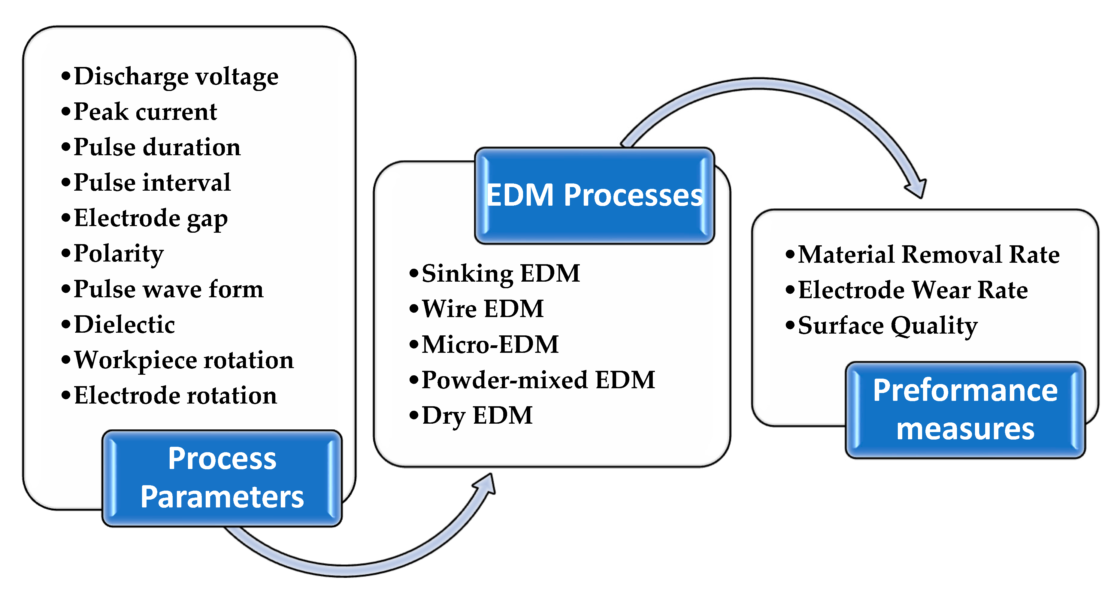
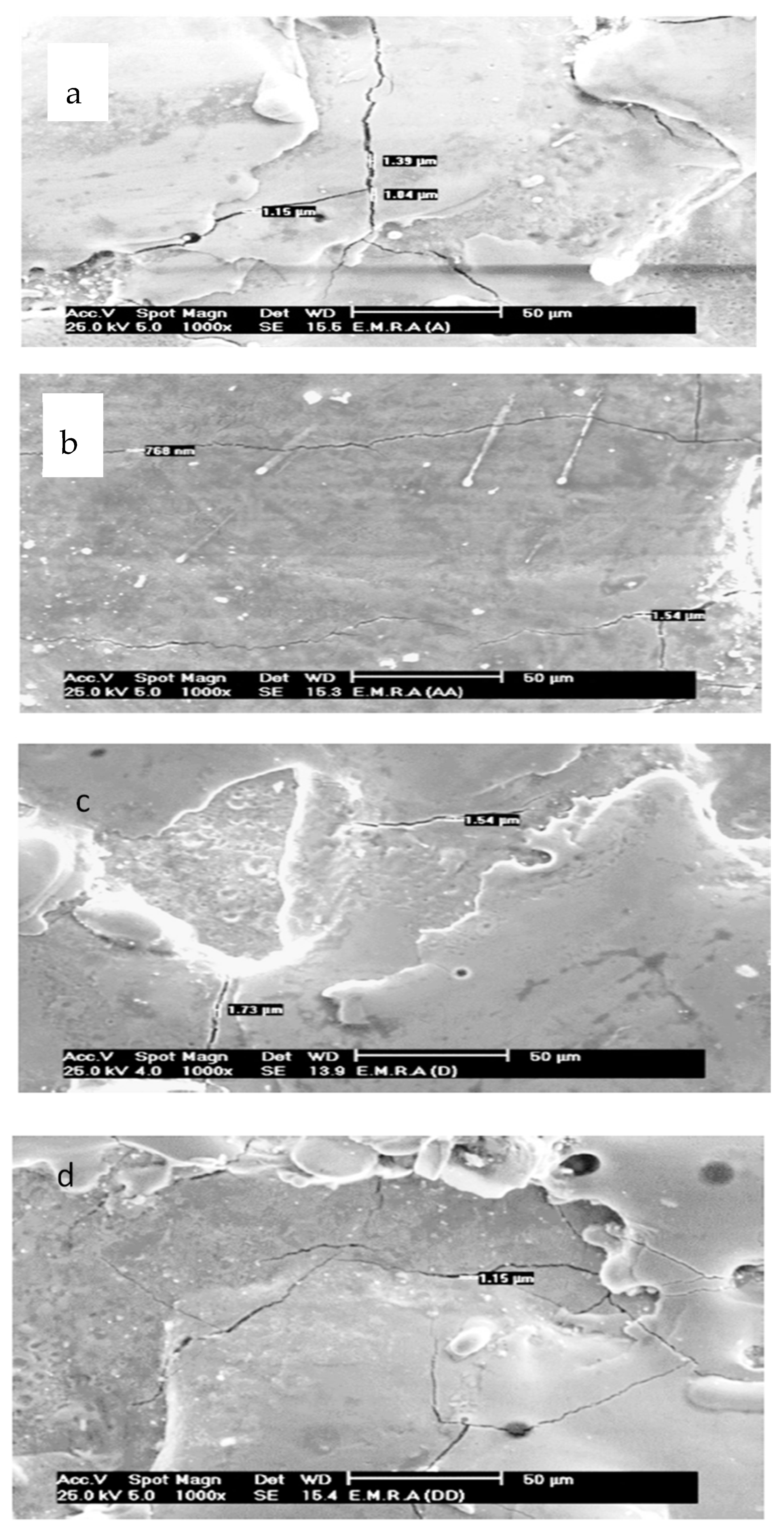
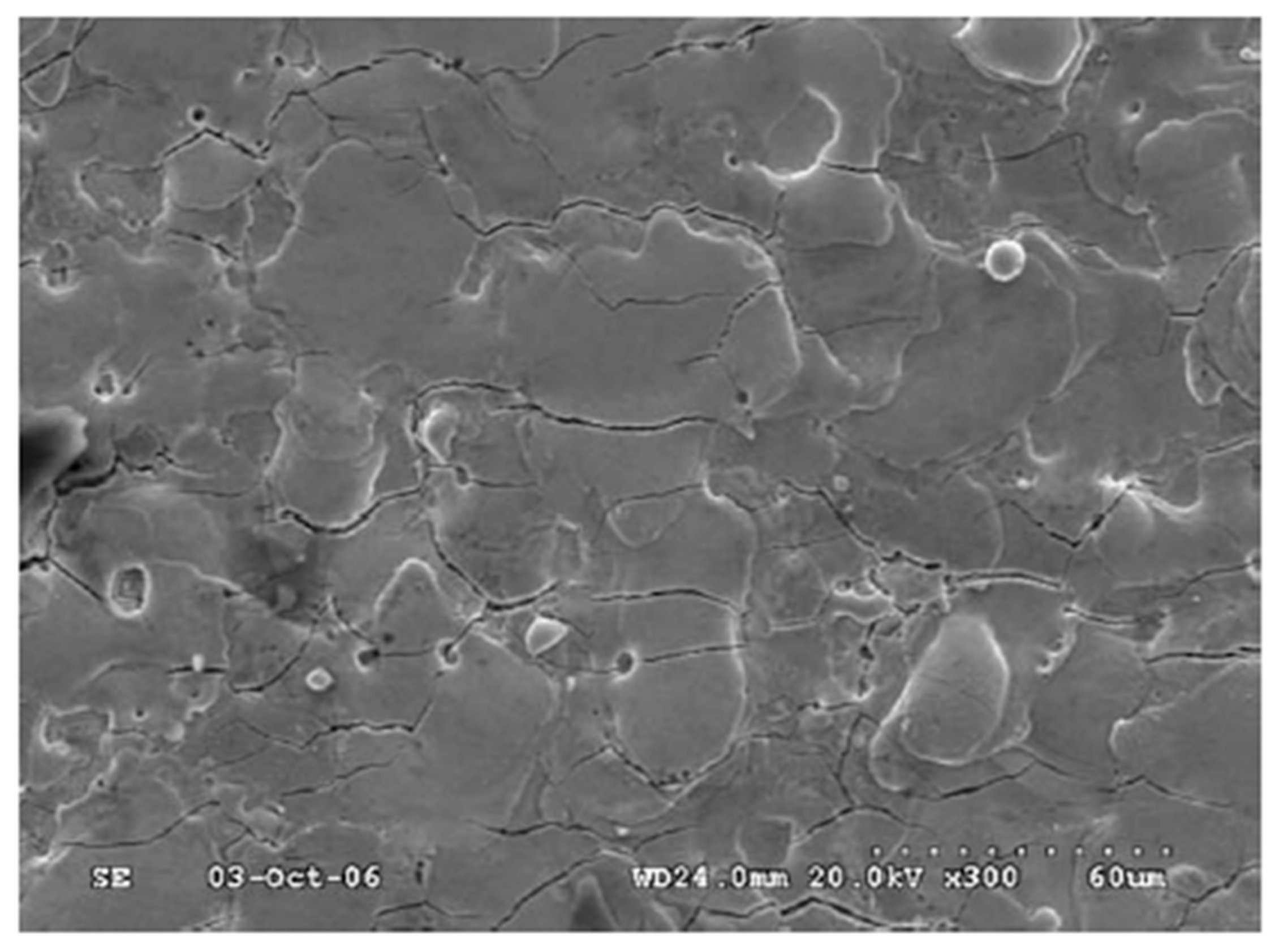
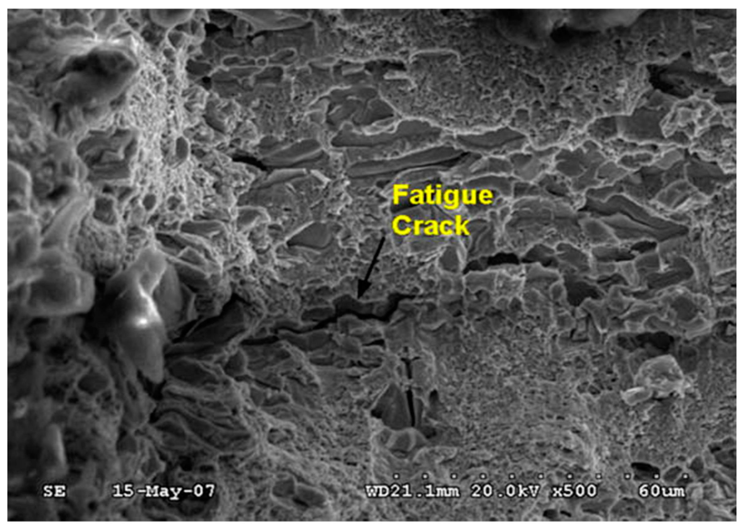
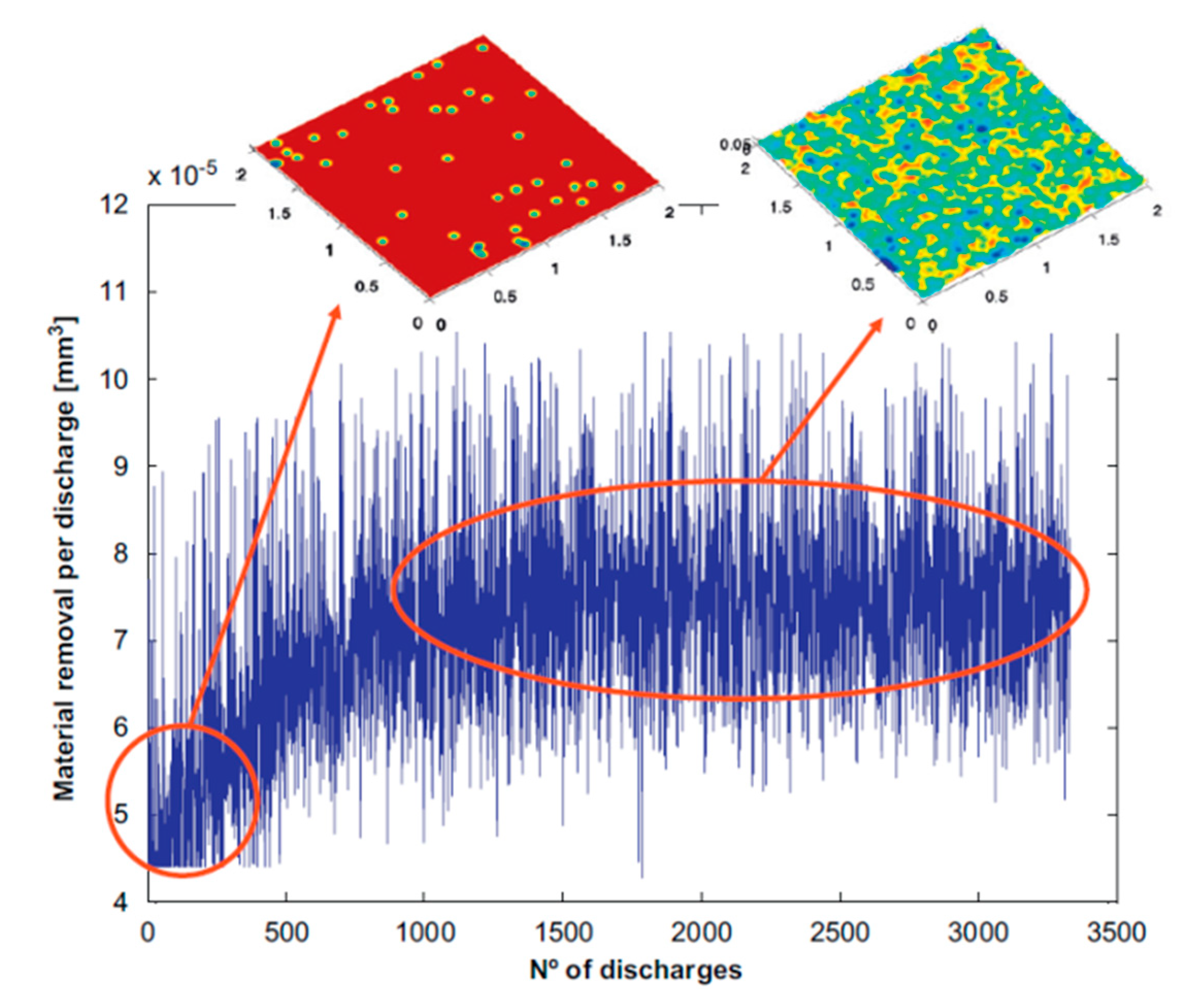
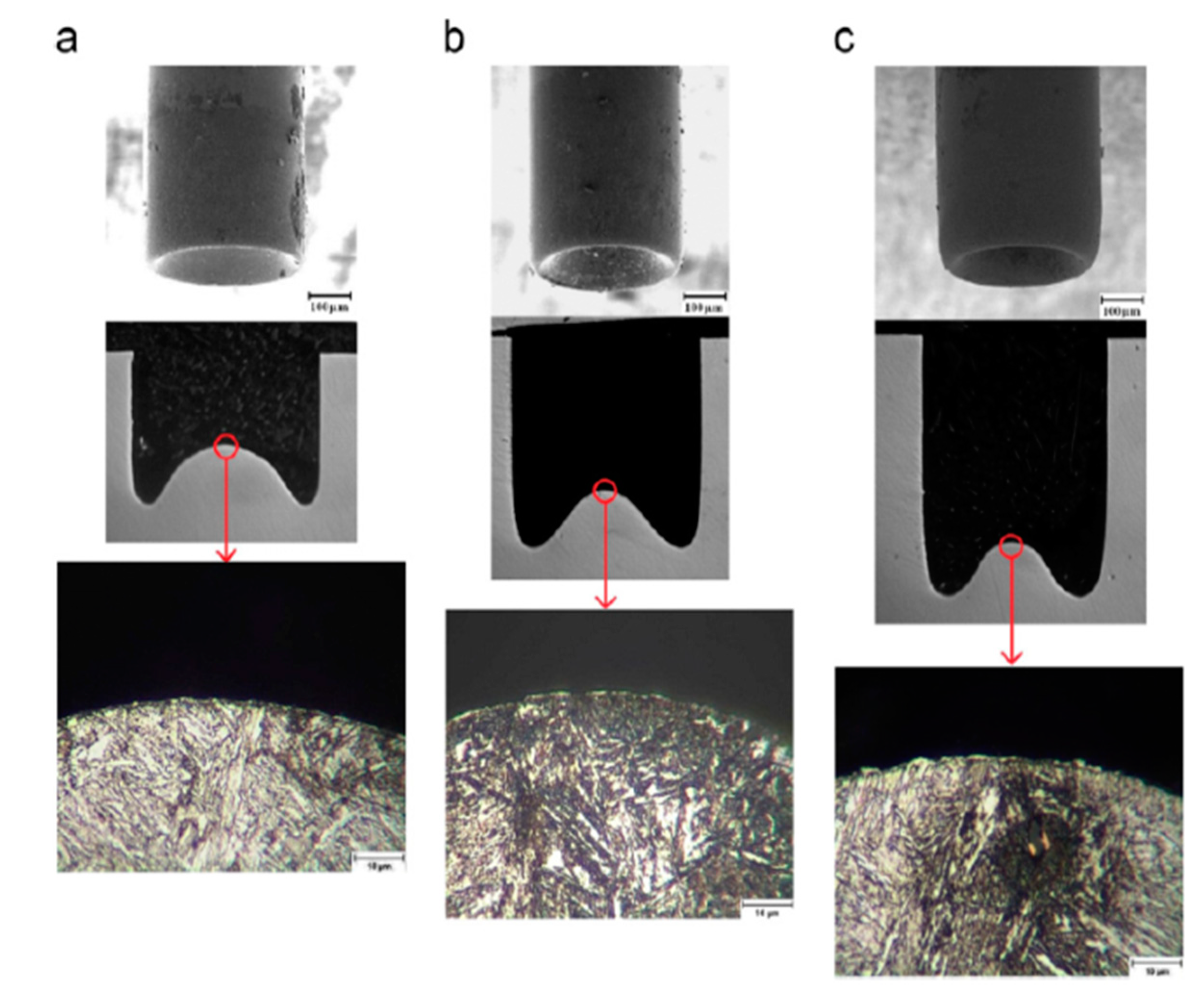
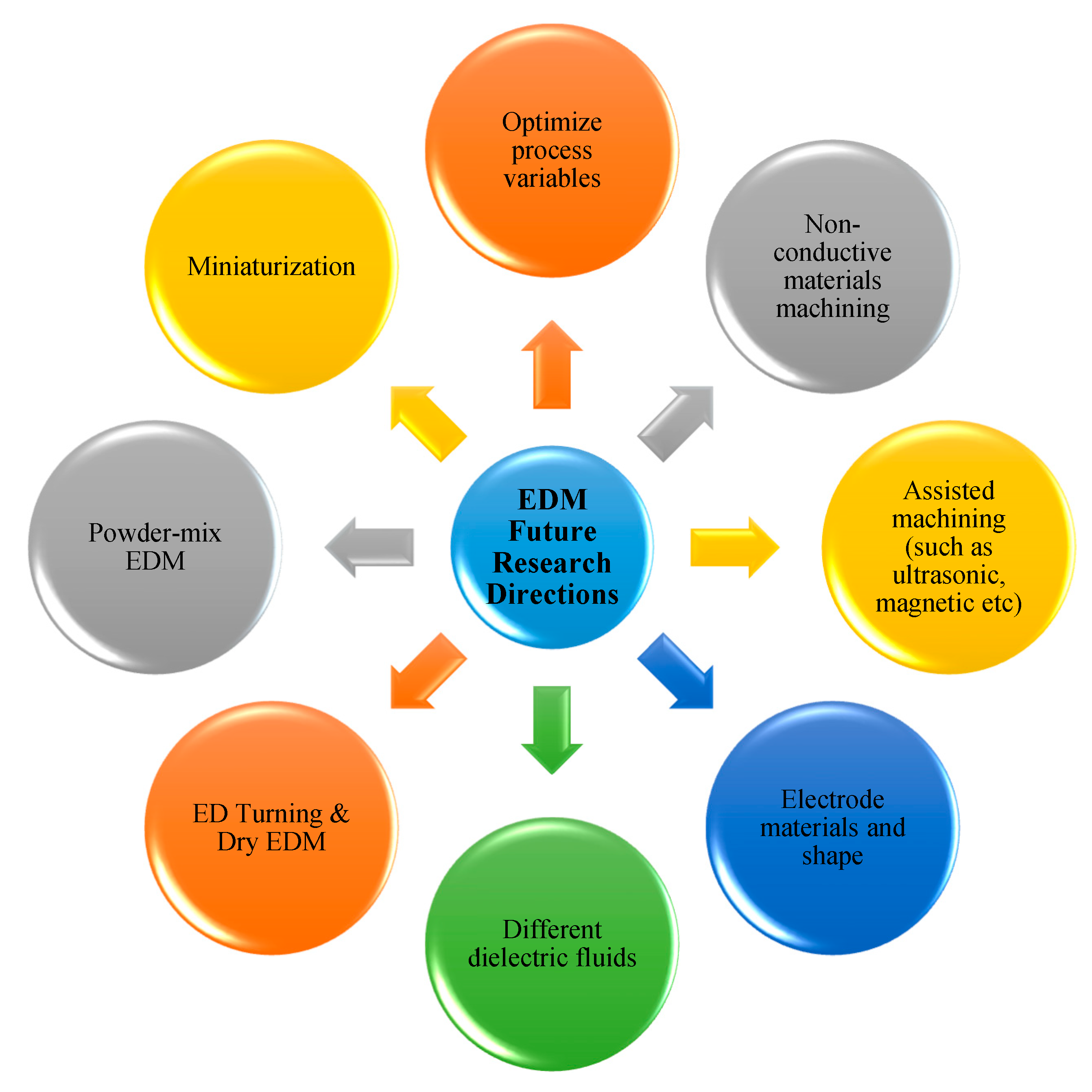
Table 1.
Details of various EDM processes used by researchers for different grades of tool steels.
| Different Grades and Corresponding Machining Operations | Composition (Weight %) | Properties |
|---|---|---|
| AISI D2 Die sinking EDM [85,104,105,106,107,108,109,110]. Wire EDM [111,112,113] Powder-mixed EDM [114,115,116]. | C 1.5, Si 0.3, Mn 0.3, Mo 1.0, Cr 12.0, Ni 0.3, V 0.8, Co 1.0. | High-carbon and high-chromium tool steel. It has high resistance to wear and abrasion. D2 grade is heat-treatable steel with hardness in the range 55–62 HRC. Its corrosion resistance depends on the percentage of chromium [117]. |
| AISI D3 Die sinking EDM [118]. Wire EDM [119]. | C 2.00, Si 0.30, Mn 0.30, Cr 12.00 | High-carbon, high-chromium tool steel. It has excellent resistance to wear and abrasion and has good dimensional stability and high compressive strength. Its hardness is in the range of 58–64 HRC [120]. |
| AISI D5 Wire EDM [121,122]. | C 1.53, Si 0.89, Mn 0.46, Cr 12.00, Mo 1.00, Ni 0.384 | Similar to other grades in group D, D5 has high carbon and high chromium content; it is the most commonly used steel among the group D steels [123]. |
| AISI D6 Die sinking EDM [124]. | Cr 12.5, C 2.05, W 1.3, Mn 0.8, Si 0.3 | In addition to high carbon and high chromium contents, D6 tool steel is alloyed with tungsten. D6 steel has high compressive strength, high wear resistance, high surface hardness, and good hardening stability [125]. |
| AISI H11 Die sinking EDM [109,126]. Dry EDM [78,127]. Powder-mixed EDM [116,128,129,130,131]. Micro-EDM [132]. | Cr 4.75–5.50, Mo 1.10–1.75, Si 0.80–1.20, V 0.80–1.20, C 0.32–0.45, Ni 0.3, Cu 0.25, Mn 0.20–0.50, P 0.03, S 0.03 | H11 grade is one of the most commonly used chromium hot-work steels. It has low carbon content and has good toughness and deep hardness due to air quenching from heat treatment [133]. |
| AISI O1 Die sinking EDM [76]. Wire EDM [134]. Powder-mixed EDM [135,136]. | C 0.85–1.00, Mn 1.00–1.40, Si 0.50, Cr 0.40–0.60, Ni 0.30, W 0.40–0.60, V 0.30, Cu 0.25, P 0.0, S 0.03 | O1 is oil-hardening tool steel. It has good machinability and dimensional stability in hardening. It also has a good combination of high surface hardness and toughness after hardening and tempering. O1 grade has good resistance to wear and abrasion due to its content of tungsten and chromium [137]. |
| AISI O2 Powder-mixed EDM [116]. | OHNS: C 0.82, Si 0.18, Mn 0.52, Cr 0.49, V 0.19, Mo 0.13, Ni 0.05; | O2 grade is oil-hardening tool steel. It has good durability, excellent wear resistance, and an ability to hold a good cutting edge [138]. |
| AISI M2 Die sinking EDM [139,140,141]. Wire EDM [142]. | C 0.78–1.05, Cr 3.75–4.50, W 5.50–6.75, Mo 4.50–5.50, V 1.75–2.20. | M2 grade is molybdenum-based high speed steel (HSS). It is a medium alloyed HSS. It has good machinability, well-balanced toughness, wear resistance, and red hardiness properties [143]. |
| SKD11 Die sinking EDM [144,145,146,147]. Wire EDM [148,149,150,151]. Dry EDM [103,152]. Powder-mixed EDM [54,136,153,154,155]. | C 1.40–1.60, Si Max 0.40, Mn Max 0.60, P Max 0.030, S Max 0.030, Cr 11.0–13.0, Mo 0.80–1.20, V 0.20–0.50. | SKD 11 is high-carbon and high-chromium alloy steel. It has high hardness and a tempering hardening effect. It also has good resistance to wear, quenching, and less deformation. Currently, it has the best wear resistance of alloy tool steel [156]. |
| SKD61 Die sinking EDM [157]. Powder-mixed EDM [136,158,159]. | C 0.35–0.42, Si 0.80–1.20, Mn 0.25–0.50, P Max 0.030, S Max 0.020, Cr 4.80–5.50, Mo 1.00–1.50, V 0.80–1.15 | KSD61 is hot-work steel; it has high creep, temperature fatigue resistance, and high toughness. It also has a good ability to be polished and good thermal conductivity [160]. |
| P20 Die sinking EDM [161,162,163,164]. Dry EDM [165]. Powder-mixed EDM [166]. | C 0.28–0.40, Si 0.20–0.80, Mn 0.60–1.00, P Max. 0.030, S Max. 0.030, Cr 1.40–2.00, Mo 0.30–0.55. | P20 tool steel is a chrome-moly alloy steel with a carbon content of approximately 0.35 to 0.40. P20 has good mirror-polish ability and less texture, making finishing easier. It distributes a uniform hardness level even across large blocks [167]. |
| BÖHLER W300 Die sinking EDM [168,169,170]. | C 0.36, Si 1.1, Cr 5.0, Mo 1.3, V 0.4 | BÖHLER W300 is hot-work tool steel and it has high impact strength and excellent hot tensile properties. |
| EN 31 Die sinking EDM [23]. Powder-mixed EDM [61]. | C 0.9–1.2, Si 0.1–0.3, Mn 0.3–0.7, Cr 1–1.6, S Max 0.025 and P Max 0.025. | EN 31 is a high-carbon alloy steel. It has high hardness with compressive strength. Moreover, it has high resistance against wear and abrasion. |
| ASP 2023 Die sinking EDM [171]. Wire EDM [172]. | C 1.28, Cr 4.1, Mo 5.0, W 6.4, V 3.1 | ASP 2023 is a high-alloy high-speed steel. It has dimension and shape stability during heat treatment. It has good toughness even for large dimensions. ASP 2023 has high hardness and good wear resistance [173]. |
| C45 Die sinking EDM [174]. Wire EDM [175]. | C 0.43–0.50, Si 0.17–0.4, Mn 0.50–0.8 | C45 is a medium carbon steel. It has high strength and hardness. It features extreme size accuracy, straightness, and concentricity combined with minimal wear in high-speed applications [176]. |
| DC 53 Wire EDM [177,178]. | C 0.95, Si 1.0, Mn 0.4, Cr 8.0, Mo 2.0, V 0.3 | DC53 has exceptional toughness, wear resistance, compressive strength, and temper resistance. It also has excellent machining characteristics [179]. |
| DIN 1.2379 Die sinking EDM [180,181,182]. | C 1.50, Si 0.30, Cr 12.0, Mo 0.80, V 0.80 | This grade has high abrasive resistance, adhesive wear resistance, and compressive strength. It also has good toughness and good dimensional stability [183]. |
| DIN 1.2738 Die sinking EDM [184]. Micro-EDM [185]. | C 0.4, Mn 1.5, Cr 1.9, Ni 1.0, Mo 0.22 | This grade has good toughness, wear resistance, stability in hardness, and high hardenability. |
| DIN 1.2714 Die sinking EDM [186]. | C 0.50–0.60, Si 0.10–0.40, Mn 0.65–0.95, Cr 1.0–1.2, P max. 0.03, S max. 0.03, V 0.07–0.12, Ni 1.50–1.80, Mo 0.45–0.55 | DIN 1.2714 has good hardenability and uniform hardness over sections with big dimensions. Furthermore, it has good strength and toughness in addition to its tempering resistance and dimensional stability [187]. |
| DIN 1.2080 Die sinking EDM [182]. | C 2.00–2.35, Mn 0.60, Si 0.60, Cr 11.00–13.50, Ni 0.30, W 1.00, V 1.00, Cu 0.25, P 0.03, S 0.03 | DIN 1.2080 is high-carbon/chromium tool steel. It has very high wear resistance and compressive strength. It can be hardened with a very slight change in size. |
| AISI 4340 Die sinking EDM [188]. | C 0.38–0.43, Si 0.15–0.35, Mn 0.6–0.8, P 0.035, S 0.04, Cr 0.7–0.9, Ni 1.65–2.0, Mo 0.2–0.3 | AISI 4340 is a heat-treatable and low-alloy steel containing chromium, nickel, and molybdenum. It has high toughness and strength in the heat-treated conditions [189]. |
| S390 Wire EDM [148]. | C 1.64, Cr 4.80, W 10.40, Co 8.00, V 4.80, Mo 2.00, Si 0.60, Mn 0.30 | This material has the ability to maintain its strength and hardness level under extremely high cutting temperatures. |
| M238 HH Die sinking EDM [74]. | C 0.36 0, Si 0.28, Mn 1.52, P 0.008, S 0.001, Cr 1.88, Mo 0.22, Ni 0.95, Al 0.021 | It is hardened and tempered plastic mold steel. There is reduction of hardness in the center of large sizes due to the Ni-addition. |
| Vanadis-4E Wire EDM [190]. | C 1.4, Si 0.4, Mn 0.4, Cr 4.7, Mo 3.5, Va 3.5 | This grade has very good ductility, high abrasive/adhesive wear resistance, and high compressive strength. Moreover, it has good dimensional stability during heat treatment, good through-hardening properties, and temper back resistance [191]. |
Table 2.
Studies for different grades of tool steel machined using various EDM processes. D-S—die sinking; W—wire; μ—micro; P-M—powder-mixed; D—dry.
Table 2.
Studies for different grades of tool steel machined using various EDM processes. D-S—die sinking; W—wire; μ—micro; P-M—powder-mixed; D—dry.
| EDM Process | |||||
|---|---|---|---|---|---|
| D-S EDM | W EDM | µ EDM | P-M EDM | D EDM | |
| Objective 1 | [23,74,105,107,118,126,139,157,161,164,170,182,186,188,192,193,194,195,196,197] | [54,119,121,122,142,177,178,190,198] | [132] | [61,116,135,154,158] | [103,115,152,159,177,178] |
| Objective 2 | [91,104,105,124,141,145,146,168,174,182,184,199,200,201] | [122,134,148,149,172,190,202] | [116,131] | [165] | |
| Objective 3 | [85,162,180,188,195,197,203,204] | [111,119,198] | [132,205,206] | [128,135,153] | [152] |
| Objective 4 | [106,109,110,126,139,140,162,163,171,193,201,207,208,209] | [113,121,175] | [166] | [103,114] | |
| Objective 5 | [162,182,192,196,210,211] | [185] | |||
| Objective 6 | [141,157,212] | [206] | [135] | [78,127,165] | |
| Objective 7 | [74,76] | [61,129,130,136,155,158] | [115,159] | ||
| Objective 8 | [108,112,144,147,169] | ||||
Table 3.
Summary of recent researches in optimizing machining process parameters of tool steel.
| No. | Authors | Process | Process parameters | Machining Performance | Remarks |
|---|---|---|---|---|---|
| 1 | (Younis et al., 2015) [182] | EDM | Is, EM, and MC | CR and RS | SR was higher when using Dura graphite than when using Poco graphite. As pulse current increases, micro-cracks increase; soft machining exhibited higher residual stresses than medium and rough machining. Poco graphite exhibited higher residual stresses compared with Dura graphite electrode. |
| 2 | (Valaki and Rathod 2015) [74] | Die sinking EDM machine | Is, Vg, Ton, and Toff | MRR, EWR, and TWR | The waste vegetable oil-based bio-dielectric fluid can be used as an alternate to hydrocarbon-, water-, and synthetic-based dielectric fluids for EDM. |
| 3 | (Zhang et al. 2014) [197] | EDM | PD and PoW | RE, D_plas, and RE | The MRR and energy efficiency were much higher with short pulse durations than with long pulse durations. The depth–diameter ratio of the crater was higher when the workpiece was positive. |
| 4 | (Sudhakara and Prasanthi 2014) [190] | W EDM | Ton Toff, Vs, Ip, WT, and DP | SR | The ranges of process parameters for wire EDM were established as follows: pulse-on time 108–128 μs, pulse-off time 47–63 μs, peak current 11–13 A, voltage 18–68 V, wire tension 2–8 g, water pressure 8–14. |
| 5 | (Aich and Banerjee 2014) [139] | EDM | I, Ton, and Toff | MRR and SR | The optimal parameters (I, Ton, and Toff) to maximize the MRR were 12.0 A, 153.9865 µs, and 50.0000 µs, respectively, and those to achieve the best SR were 3.0 A, 200.000 µs, and 126.8332 µs, respectively. |
| 6 | (Balasubramanian and Senthilvelan 2014) [118] | EDM | Ip, Ton, DP and D_tool | MRR, TWR, and SR | For EN-8 material, the mean MRR value was (72.4 mm3/min), it was higher for the cast electrode than for the sintered electrode. The TWR was (12.73 mm3/min); it was lower for the cast electrode than for the sintered electrode. For die steel D3, the mean value of MRR was higher for the cast electrode than for the sintered electrode. The TWR was marginally lower for the cast electrode than for the sintered electrode. The mean value of SR was marginally lower for the sintered electrode than for the cast electrode. |
| 7 | (Sahu, Mohanty et al. 2013) [107] | EDM | Ip, Ton, τ, and Dp | MRR, TWR, SR, and r1/r2 | The values of discharge current (Ip), pulse-on time (Ton), duty factor(τ), and flushing pressure (Fp) that achieved the best quality were 7 A, 200 µs, 90%, and 0.4 kg/m2, respectively. The optimal obtained response parameters were MRR = 13.9600 mm3/min, TWR = 0.0201 mm3/min, Ra = 4.9300 µm, and circularity = 0.8401. |
| 8 | (Klocke et al. 2013) [170] | EDM | I, PD, and GG | MRR and TWR | The discharge current was the main parameter effect on the MRR and the discharge duration was the main parameter effect on the TWR. There was no direct link between the grain size and the two response parameters MRR and TWR. MRR increases as the current increases and it decreases as the pulse duration and electrical conductivity of graphite grade increase. Relative TWR slightly decreases as the current increase and slightly increases as the electrical conductivity of graphite grade increase, whereas it sharply decreases as pulse duration increases. |
| 9 | (Shabgard et al. 2013) [126] | EDM | Is and Ton | PFE | Plasma flushing efficiency increases as pulse current increases and it decreases as pulse-on time increases. Recast layer thickness increases as pulse-on time increases. |
| 10 | (Fan, Bai et al. 2013) [198] | W EDM-HS | C | T and SR | Best surface roughness and the minimum achievable maximum processing thickness were obtained upon selecting a capacitance that achieved triple the charging time constant equal to pulse duration. |
| 11 | (Srivastava and Pandey, 2012) [141] | EDM | Is, Ton, τ, and Vg | MRR, EWR, and SR | EWR and surface roughness were significantly lower in the ultrasonic assisted cryogenically cooled copper electrode (UACEDM) process than in the conventional EDM process and MRR was approximately the same as for conventional EDM. Surface integrity of the workpiece machined by UACEDM was better than that machined by the conventional EDM process. In UACEDM, the density of cracks increases as the discharge current increases. Induced stress increases as pulse-on duration and crack formation increase. |
| 12 | (Teimouri and Baseri 2012) [196] | EDM | DE, H, and w | MRR and SR | The rotary tool electrode improved the machining performance. The magnetic field reduced the inactive pulses and helped the ionization. As rotational speed increases, Ra decreases. |
| 13 | (Kumar and Batra 2012) [116] | EDM | Ip, Ton, and Toff | µH | Machining conditions allowing material transfer (of tungsten and carbon to the workpiece surface) by EDM were at a discharge current less than 5 A, shorter pulse-on time less than 10 µs, and longer pulse-off time more than 50 µs with negative polarity of the tool electrode. The most significant factor for surface modification was peak current. |
| 14 | (Sivapira et al. 2011) [194] | EDM | Ip, PD, DL, and DF | S_green | The optimal machining performance for green EDM was with peak current = 4.5 A, pulse duration = 261 µs, dielectric level = 40 mm, and flushing pressure = 0.5 kg/cm2. |
| 15 | (Çaydaş et al. 2009) [121] | Wire EDM | PD, V, DP, and S-wire | TWL and Avr_SR | The developed approach greatly improved the surface roughness and white layer thickness in wire EDM. |
| 16 | (Lin et al. 2009) [157] | EDM | P, Ip, PD, IH, V, and Vs | MRR and SR | The MRR of magnetic force-assisted EDM was almost three times as large as the value for standard EDM. Employing magnetic force-assisted EDM improved the lower relative electrode wear ratio (REWR) from 1.03% to 0.33% and reduced the SR from Ra 3.15 to 3.04 µm on average. Discharge craters were bigger and deeper, and micro-cracks were more common in standard EDM than that magnetic force-assisted EDM. In the magnetic force-assisted EDM process, MRR was significantly affected by polarity and peak current and SR was significantly affected by peak current. The optimal parameters which maximized MRR were negative polarity, peak current = 5 A, auxiliary current = 1.2 A, pulse duration = 460 µs, no-load voltage = 120 V, and servo reference voltage = 10 V. The optimal parameters which achieved minimum SR were positive polarity, peak current = 20 A, auxiliary current = 0.8 A, pulse duration = 460 µs, no-load voltage = 200 V, and servo reference voltage = 10 V. |
| 17 | (Wu et al. 2009) [159] | EDM | Ip, PD, V, and Vg | MRR and SR | Adding 30 g/L of Span 20 to kerosene increased the MRR by 40%. Selecting proper working parameters improved MRR by 85%. SR was not deteriorated even at MRR. Adding Span 20 (30 g/L) decreases both the concentrated discharge energy and the unstable discharge phenomenon. The thickness of recast layer on the workpiece of kerosene was less than the thickness of pure kerosene. The surfactant increased the conductivity of kerosene and shorted the delay time, thus improved the machining efficiency. |
| 18 | (Matoorian et al. 2008) [193] | EDM | IN, Ton, Toff, V, S, and W | MRR | The factors most influencing the cost-effectiveness of the EDT process were intensity, spindle speed, servo, and pulse-on time in the following combination: 6 A, 50 µs, 20 µs, 120 V, 30 V, and 40 rpm, respectively. The actual and predicted values of MRR were 0.023 and 0.021, respectively. |
| 19 | (Haron et al. 2008) [192] | EDM | I, EM, and D_tool | MRR | The copper electrode achieved higher MRR than the graphite electrode. It was recommended to use the copper electrode for rough cutting and the graphite electrode for finish cutting. |
| 20 | (Haddad and Tehrani 2008) [119] | Wire EDM | P, Toff, V, and w | MRR | The only influential design factors and interaction effects of machining parameters on the MRR in the cylindrical wire electrical discharge turning process were power, voltage, pulse-off time, and spindle rotational speed. |
| 21 | (Kansal et al. 2008) [114] | Powder-mixed electric discharge machining (PMEDM) | I, Ton, Toff, DE, and PCH | TD | The simulation results showed that PMEDM produced smaller and shallower craters than EDM under the same set of machining conditions. |
| 22 | (Kanlayasiri and Boonmung 2007) [177,178] | Wire EDM | Ton, Toff, Ip, and WT | SR | The main parameters of wire EDM affecting the SR of DC53 die steel were pulse-on time and pulse-peak current. The SR increases as the pulse-on time and pulse-peak current increase. |
| 23 | (Kansal et al. 2007) [115] | Powder-mixed EDM | Ip, Ton, Toff, PCON, GN, and NF | MRR | MRR in powder-mixed EDM was significantly affected by peak current, concentration of the silicon powder, pulse-on time, pulse-off time, and gain. Among all, peak current and concentration of silicon powder were the parameters most influencing MRR. The optimum c parameters were peak current = 10 A, powder concentration = 4 g/L, pulse-on time = 100 μs, pulse-off time = 15 μs, and gain = 1 mm/s. |
| 24 | (Kiyak and Cakır 2007) [164] | EDM | Is, Ton, and Toff | SR | The SR increases as pulsed current and pulse time increase. SR decreases as current and pulse time decrease and pulse pause time increases. For rough EDM machining, the machine power should be 25% of the produced power with current, pulse time, and pulse pause time of 16 A, 6 µs, and 3 µs, respectively. For finish machining, the machine had 50% of produced power with current, pulse time, and pulse pause time of 8 A, 6 µs, and 3 µs, respectively. |
| 25 | (Tzeng and Chen 2007) [154] | EDM | V, Pd, τ, Ip, PCON, regular distance for electrode lift, time interval for electrode lift, and powder size | Precision and accuracy of the high-speed EDM | 81.5% of the high-speed EDM process variance was due to pulse time, duty cycle, and peak value of discharge current. The best parameter combinations achieving precision and accuracy of the high-speed EDM process were open-circuit voltage of 120 V, pulse duration of 12 µs, duty cycle of 66%, pulse-peak current of 12 A, powder concentration of 0.5 cm3/L, regular distance for electrode lift of 12 mm, time interval for electrode lift of 0.6 s, and powder size of 40 µm. |
| 26 | (Zarepour et al. 2007) [186] | EDM | Ton, I, and V | TWR | Pulse-on time, current, and pre-EDM roughing as factors, along with pulse-on time/current, pulse-on time/pre-EDM roughing, and current/pre-EDM roughing as interactions, were found to have significant effects on electrode wear of the EDM process of DIN 1.2714. |
| 27 | (Yilmaz et al. 2006) [188] | EDM | Is, PD, PI, FR, and GC | EWR, better SR, and ER | Providing a selection tool enables an unskilled user to select necessary parameters which achieve less electrode wear, better surface quality, and high erosion rate for both finish and rough machining. |
| 28 | (Wu et al. 2005) [158] | EDM | P, PD, V, Vg, PCON, and SCON | SR | The surface roughness of the workpiece in the EDM process was improved by adding surfactant and aluminum powder to the dielectric fluid. The EDM parameters which achieved optimal surface roughness (0.172 µm) were Al powder concentration of 0.1 g/L, positive polarity, peak current of 0.3 A, peak duration of 1.5 µs, and surfactant concentration of 0.25 g/L. The gap distance was increased by adding aluminum powder or surfactant to the EDM dielectric fluid. Dielectric mixed with both aluminum powder and surfactant achieved an optimally thin recast layer. The mixture also improved the SR by 60% compared to the SR under normal dielectric. |
| 29 | (Kansal et al. 2005) [61] | Powder-mixed EDM | Ton, τ, Ip, and PCON | MRR and SR | MRR increases as the concentration of the silicon powder increases. SR decreases as the concentration of the silicon powder increases. Peak current and concentration of the silicon powder were the parameters most affecting MRR and SR. MRR increases and SR decreases as the combination of peak current and concentration increase. |
| 30 | (Amorim and Weingaertner 2005) [161] | EDM | Is, PD, PI, V, P, and G_mod | MRR, WWR, and SR | The maximum MRR of 8 mm3/min was obtained at a discharge current of 8 A and a discharge duration of 50 µs, with positive electrode polarity and a generator under iso-energetic mode. The minimum average SR of 0.6 µm was obtained at a discharge current of 3 A, discharge duration of 12.8 µs, negative electrode polarity, and generator under iso-energetic mode. The volumetric relative wear for EDM with a negative electrode polarity was much higher than that with positive electrode polarity. |
| 31 | (Hasçalýk and Çaydaş 2004) [122] | W EDM | PD, V, S-wire, and DP | SR and MS | The thickness white layer was proportional to the magnitude of the energy impinging on that surface. The density of cracks in the white layer and SR increase as the pulse duration and open-circuit voltage increase. Dielectric fluid pressure and wire speed did not have much of an influence on SR. The surface of all workpieces was harder than the bulk material, while the heat-affected zone was softer in quenched and tempered workpieces. |
| 32 | (Kunieda et al. 2004) [103] | Dry EDM | G and Gain | MRR | The monotonous oscillation using a piezoelectric actuator was not useful in dry EDM. |
| 33 | (Singh et al. 2004) [23] | EDM | Is and EM | MRR, D_over, EWR, and SR | Among copper, copper tungsten, brass, and aluminum, copper and aluminum electrodes offered higher MRR and SR during machining of En-31 work material in EDM, where the electrodes of these two materials produced low diametrical overcut. The copper–tungsten electrode offered low values of SR at high discharge currents. Copper and copper–tungsten electrodes offered low EWR. In contrast, brass resulted in the highest EWR. Among the four electrode materials, copper was the best to machine En-31 material. |
| 34 | (Lin et al. 2000) [54]; Puri and Bhattacharyya 2003) [142] | W EDM | Ton, Toff, Ip, τ, Vp, S-wire, WT, Vs, DP, and F | Avg_CS and G-InI | The parameters most affecting the average cutting speed during rough cutting were pulse-on time, pulse-off time, and pulse-peak current, and those during trim cutting were pulse-on time and constant cutting. The parameter most affecting the SR during rough cutting was pulse-peak current, and those during trim cutting were pulse-on time, pulse-peak voltage, servo spark gap set voltage, dielectric flow rate, wire tool offset, and constant cutting speed. The factors most affecting geometrical inaccuracy due to wire lag during rough cutting were pulse-on time, pulse-off time, pulse-peak current, and pulse-peak voltage, and those during trim cutting were wire tension, servo spark gap set voltage, wire tool offset, and constant cutting speed. |
| 35 | (Guu et al. 2003) [105] | EDM | Is, Ton, and Toff | T_RL, SR, and σres | The recast layer becomes thicker as the pulse current and pulse-on duration increase. As the peak current is achieved, the melting of the material and damage of the surface and subsurface area increase. |
| 36 | (Ghoreishi and Atkinson 2002) [135] | EDM | A, w, LF, and HF | MRR, TWR, and SR | High-frequency vibration had a notable effect on the MRR. The combination of low-frequency vibration and electrode rotation did not give a satisfactory effect on MRR. The combination of ultrasonic vibration and electrode rotation led to an increase in MRR. The combination of high-frequency vibration and electrode rotation was the best for the finishing cut. In the semi-finishing cut, the vibro-rotary EDM increased MRR by 35% and 100% compared to vibratory and rotary EDM, respectively. |
| 37 | (Kunieda and Furudate 2001) [152] | Dry EDM | The MRR and waviness could be improved by increasing the wire winding speed and decreasing the actual depth of cut. |
Table 4.
General effect of major operating parameters on key performance measures.
| Discharge Current | Pulse-On Time | Pulse-Off Time | Voltage | Electrode Rotation Speed | |
|---|---|---|---|---|---|
MRR  |  |  |  |  |  |
EWR  |  |  |  |  |  |
SR  |  |  |  |  |  |
© 2020 by the authors. Licensee MDPI, Basel, Switzerland. This article is an open access article distributed under the terms and conditions of the Creative Commons Attribution (CC BY) license (http://creativecommons.org/licenses/by/4.0/).
Share and Cite
MDPI and ACS Style
Qudeiri, J.E.A.; Zaiout, A.; Mourad, A.-H.I.; Abidi, M.H.; Elkaseer, A. Principles and Characteristics of Different EDM Processes in Machining Tool and Die Steels. Appl. Sci. 2020, 10, 2082. https://doi.org/10.3390/app10062082
AMA Style
Qudeiri JEA, Zaiout A, Mourad A-HI, Abidi MH, Elkaseer A. Principles and Characteristics of Different EDM Processes in Machining Tool and Die Steels. Applied Sciences. 2020; 10(6):2082. https://doi.org/10.3390/app10062082
Chicago/Turabian StyleQudeiri, Jaber E. Abu, Aiman Zaiout, Abdel-Hamid I. Mourad, Mustufa Haider Abidi, and Ahmed Elkaseer. 2020. "Principles and Characteristics of Different EDM Processes in Machining Tool and Die Steels" Applied Sciences 10, no. 6: 2082. https://doi.org/10.3390/app10062082
Note that from the first issue of 2016, this journal uses article numbers instead of page numbers. See further details here.