A Design Criterion Based on Shear Energy Consumption for Robotic Harvesting Tools


Centre for Automation and Robotics, UPM-CSIC, Carretera CAMPO-REAL Km 0.2, Arganda del Rey, 28500 Madrid, Spain
*
Authors to whom correspondence should be addressed.
Agronomy 2020, 10(5), 734; https://doi.org/10.3390/agronomy10050734
Submission received: 13 April 2020
/
Revised: 13 May 2020
/
Accepted: 15 May 2020
/
Published: 20 May 2020
(This article belongs to the Special Issue Towards Artificially Intelligent Robotics for Agriculture – Current Developments and New Trends)
Abstract
:Smart and precise agriculture has increasingly been developed in the last decade, and with that, the idea of optimizing the tools commonly used in this field. One way to improve these devices, particularly cutting tools conceived for harvesting purposes, is to measure the shear energy consumption required for a particular plant. The aim of this research is to establish both a design criterion for cutting grippers and a quantifiable way to evaluate and classify a harvesting tool for a specific crop. This design criterion could help to minimize energy consumption in future harvesting robots, making them more energy-efficient.
1. Introduction
The world’s population is increasing rapidly. According to United Nations projections, the populations could reach 9.7 billion people in 2050 and 11.2 billion by 2100 [1]. Due to this situation, the primary sector, and more specifically, the agricultural sector, must undergo a transformation process that allows it to double productivity to meet the growing demand. In addition, the loss of farmers combined with their average age, makes clear the need for efficient increases in the manifold agricultural tasks [2,3,4,5].
One way to address this transformation process is to introduce technologies that have been traditionally used in industry into the primary sector. Currently, robotics and automation have achieved important advances that can contribute in this regard, including improved adaptation to different environmental conditions and high operating speeds. Nevertheless, aspects such as the reliability and cost of robots have to be solved to profitably introduce these technologies in the agricultural sector [6]. Given the aforementioned situation, the trend in the agricultural sector is to develop intelligent and efficient machines [7] that can assist humans in tough and mostly repetitive tasks and improve conventional agricultural productivity.
In the last 30 years, a large amount of research effort has focused on developing robots for automating harvesting processes. To achieve this goal, special emphasis has been placed on advancing general topics such as machine vision and detection systems [8,9,10,11], decision-making architectures [12,13,14], autonomous navigation [15] and dexterous manipulation [16]. In addition, some authors have focused on automating the harvesting of specific crops, which can be divided into three main groups according to the characteristics of the crop stalk. This first group are those that can be harvested by an indirect mechanical movement towards the fruit through a force applied to the plant itself, such as the harvesting of olives [17], almonds [18] and pistachio nuts [19], and this process does not include direct contact with the stalk of the same. The second group are those that, due to the fragile structure of the plant, cannot be shaken but need a mechanical force to be applied to the fruit itself; these actions are also known as plucking patterns (e.g., twisting, pulling and bending) actions and cause the fruits to be loosened from their peduncles [20]. Examples from this group are the harvesting of strawberries [20,21], apples [22,23,24,25] and tomatoes [26,27,28,29]. The final group are those that need a direct mechanical movement, or other type of cutting method, applied directly to the stalk, because due to their morphology, they are connected to the plant by a hard peduncle that must be cut, such as in the harvesting of aubergines [30], melons [31], oranges [32], cucumbers [33] and peppers [34,35,36]. The aim of this article is to propose a design criterion for tools used to harvest this last group of fruits and vegetables that require a cutting process.
Although different types of harvesting tools and cutting devices have been developed to collect fruit [29,30,32,35,36,37,38,39,40,41], their designs have been accomplished empirically in many cases without considering the optimal design as an objective in itself. On the other hand, there are a multitude of patented tools in the market aimed at cutting the stalks of a wide range of plants [42,43,44]. Nevertheless, due to the private development of these tools, it is not possible to find in the literature any type of study or test carried out for their designs that details the performance or optimization of the required cutting energy. To increase the efficiency of these tools, implement new technologies, and provide a significant improvement in the agricultural sector, several researchers [45] have advocated for conducting experiments related to measuring the energy required to cut plant stalks. In this way, with quantifiable data and reliable conclusions, it will be feasible to redesign cutting machines to reduce their energy costs and increase their potential applicability in autonomous tasks [46,47].
With all these facts in mind, this article presents a novel design criterion for robotic harvesting grippers based on an analysis of shear energy measurements and other mechanical properties of crop stalks, such as shear force and ultimate shear stress. The proposed criterion will enable not only the design of tools that will reduce the energy consumed in pursuit of increasing the autonomy of agricultural harvesting robots but also the testing and benchmarking of different harvesting tool designs.
To carry out this study, cutting tests are performed on aubergines, also known as eggplant or brinjal, whose production has experienced a significant increase in recent years, with Spain being the first exporting country in the European Union, although countries such as China and India stand out in their cultivation. This increase in production shows the importance of aubergines agriculturally and economically. In addition, vegetables such as aubergines need to be carefully harvested, and only a cutting method is valid since any plucking technique could damage the plant [48]. Finally, this particular crop was also chosen because there are few research studies on it [30,49,50], and therefore, it offers new opportunities for future work.
The rest of this article is organized as follows. Section 2 presents a literature overview referring to studies of shear energy consumption and methods that have been successfully applied to measure its properties. Section 3 describes the materials and the various systems used in the experimental tests. Having stated the technical aspects, the following sections focus on scientific findings. Thus, Section 4 describes the methodology of the cutting experiments as well as the mechanical cutting parameters obtained from the experiments. Section 5 discusses the main results obtained in the tests that were carried out. Section 6 describes the steps to obtain the parameters required to meet the proposed design criterion for cutting tools based on a reduction in the energy consumption. Finally, Section 7 summarizes the major conclusions.
2. Research Background
Achieving improvement in the efficiency of production processes by studying ways to minimize energy consumption is a decisive competitive factor in the industrial sector, particularly in the fields of manufacturing engineering and life cycle engineering [51]. Some expected outcomes of this improvement are target-oriented machine process design, increased flexibility in production, reductions in manufacturing costs and minimization of the environmental impact [52].
In the field of machining process and computer numerical control (CNC) machines, there are numerous studies with the aim of reducing cutting energy consumption by taking into consideration the different materials of the cutting mechanism, the angles involved between the cutting tool and the raw material, and the optimal route for the desired machining [53,54]. Some authors [53] classify the factors affecting the cutting energy into four groups:
- Tool conditions: material, insert geometry and tool wear;
- Workpiece material: hardness and machinability;
- Cutting parameters: speed, feed, and depth of cut;
- Cutting fluids: whether a coolant is used.
Following the idea mentioned in the introduction, where one way to improve the technologies used in the agricultural sector is to adapt solutions used in the industrial sector, some lessons have been learned from machining and CNC studies that can be applied for the design of tools in the agricultural sector. For instance, one lesson is that the energy consumption increases not only when machining is taking place but also in the electronics of the machine and other supports needed to perform the control of the various tasks [53,55]. Therefore, the goal is to measure not only the consumption of the cutting device (motor, blades, etc.) but also its support devices and control electronics. In fact, some authors emphasize that when the power consumption of a machine’s supporting elements is reduced to a small fraction of the overall consumption, this is when the cutting power becomes crucial [56]. Another lesson learned is the careful study that has to be conducted regarding the angles involved in the cutting process as well as the properties of the material to be cut.
In the agricultural context, the mechanical properties of different types of crop stalks have been investigated by performing laborious experiments [57,58,59,60,61,62]. What is known so far is that crop stalks, as a biological material, have complex structures and exhibit anisotropy (i.e., mechanical properties vary according to the direction of measurement), viscoelasticity (i.e., property of materials that exhibit both viscous and elastic characteristics when undergoing deformation), and other rheological parameters that differ substantially from other materials used in engineering [45]. In fact, some researchers [63,64,65,66,67,68] have shown that these mechanical properties vary depending on different maturity stages or different moisture contents, leading to different tensile, compressive, shear and bending behaviours. Therefore, the formulation of new material theories for modelling the mechanical properties of crop stalks is not only highly encouraged [45] but also of growing importance for the development of agricultural engineering.
For agricultural applications, a case of success, in terms of sugarcane harvesting, was the improvement of the machinery for stripping leaves from the stalks. In [57], it was demonstrated, through several experimental tests, that fracture by transversal stress is the most convenient way to facilitate the removal of sugarcane leaves. Other studies related to sugarcane, as reviewed by [69], involved the study of the blade cutting velocity [70], analysis of the effects of the different angles in the blade, discs involved in the harvest [71] and optimization of the blade shape [72,73,74].
Studies conducted to find the ideal cutting orientation for maize stalks [75] are also noteworthy. In this sense, authors have stressed that the orientation of the corn stem significantly affects the necessary mechanical strength, as well as the energy consumption and stress, and identified different stages in the cutting of this plant. Another study on corn plants was carried out by [76], in which the different phases of cutting in terms of mechanical properties were characterized according to the physical properties of the stem.
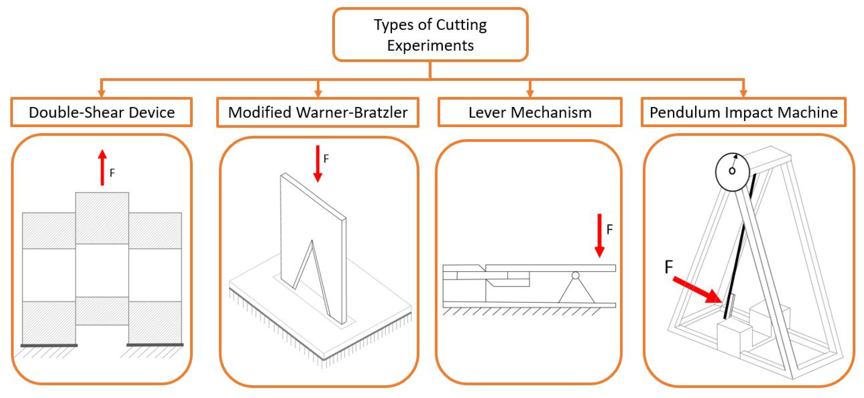
On the other hand, four different devices that have presented in the literature to measure shear properties can be highlighted. The first is a double-shear device attached to a universal testing machine (UTM), used for measuring the force, tensile and shear stress, as well as the tensile and shear energy for different biomass stems [59]. This device consists of a pattern of machined holes, and some of its main advantages are that it can be adapted to stalks of different diameter and uses a UTM as a base. However, it has disadvantages such as: (i) the complexity of manufacturing the various parts that make up the head, as well as the need to make the hole with the exact diameter of the peduncle, since otherwise, the measurement may record deviations due to deformation, which are not desirable; (ii) it may also impose constraints in the selection of the samples, since they must be long enough to go through the whole system. The second device [77,78,79] uses an impact pendulum or a Charpy pendulum modified with a Blade. This device is useful to make measurements directly in the field, since it does not require any electronic elements. As a disadvantage, this system has to be manufactured expressly for the desired purpose and the acquisition of the shearing characteristics of the material is done indirectly, through the principle of energy conservation. The third device [61] is a cutting machine based on a lever mechanism. In this case, the shear characteristics of the material can be obtained directly, but its main disadvantage is that all its parts must be manufactured specifically for the required shear experiment. The last one, proposed by [75,80], is a modified Warner–Bratzler shear device [46]. A Warner–Bratzler test is traditionally used for typical soft food products, such as meat and its derivatives [81,82,83,84]. The original Warner–Bratzler device consists of a blade, which can be of two types: one for rectangular specimens that has a straight blunt blade and the second for cylindrical specimens that has a notched blunt blade. This device has been extensively covered in the literature and is the easiest to implement, as only the blades need to be manufactured. In addition, the system can be easily adapted to various diameters of peduncle by means of clamps and the measurements of the shear characteristics of the material can be obtained directly.
All these methods of cutting experiments are shown schematically in Figure 1.
3. Materials
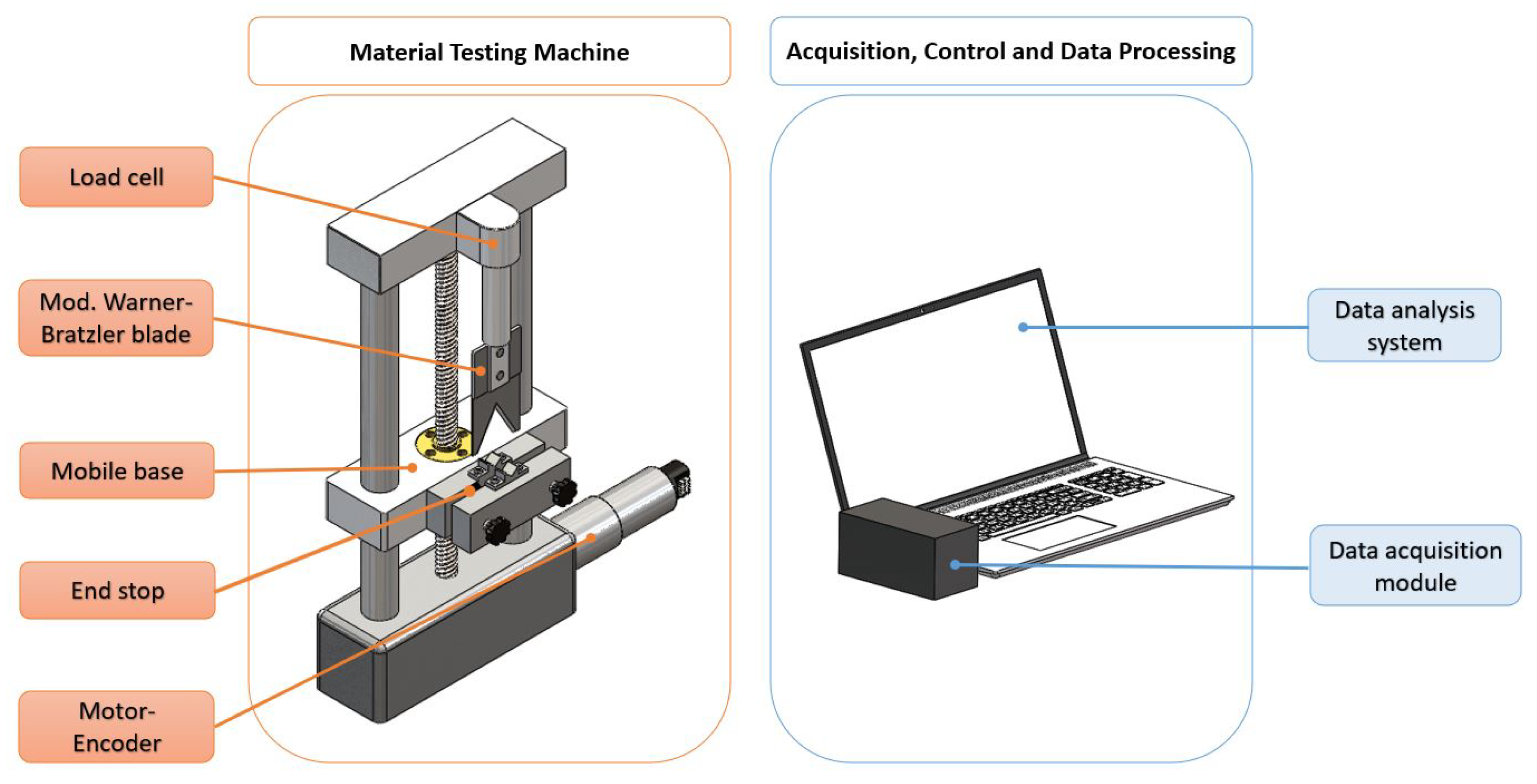
Before the proposed methodology is explained, the various systems required for its implementation are described below. Figure 2 shows a schematic of the systems used, divided into two blocks: (i) a material testing machine that includes all the elements involved in the direct testing of a crop, comprising the load cell, the motor-encoder subgroup and the modified Warner–Bratzler blade; (ii) an acquisition module and processing data system, which comprise the hardware and software that is in charge of amplifying and conditioning the signal coming from the load cell, controlling the cut by means of the motor-encoder, and graphing and calculating all the information of the experiments.
3.1. Material Testing Machine
In the experiments, a custom-made testing machine that was based on a modified Warner–Bratzler shear device was used. However, in this modified Warner–Bratzler shear device, the blunt blades were sharpened to make them more suitable for cutting tough material. In addition, the machine was based on two columns with a spindle in the middle, and this design provided sufficient precision to perform the experiments. The movement of the base was produced by a motor with a gearbox. The motor position was read by a dual-channel encoder, which, through various reductions, provided the position of the mobile base. In particular, the mobile base could make upward and downward movements with 0.5 mm precision. The force exerted on the material to be examined was measured by a load cell housed in the upper part of the machine and attached to the modified Warner–Bratzler device, as shown in Figure 2.
3.1.1. Load Cell
The compression load cell that was selected was an Entran ELW-D1-500N, whose technical specifications are listed in Table 1.
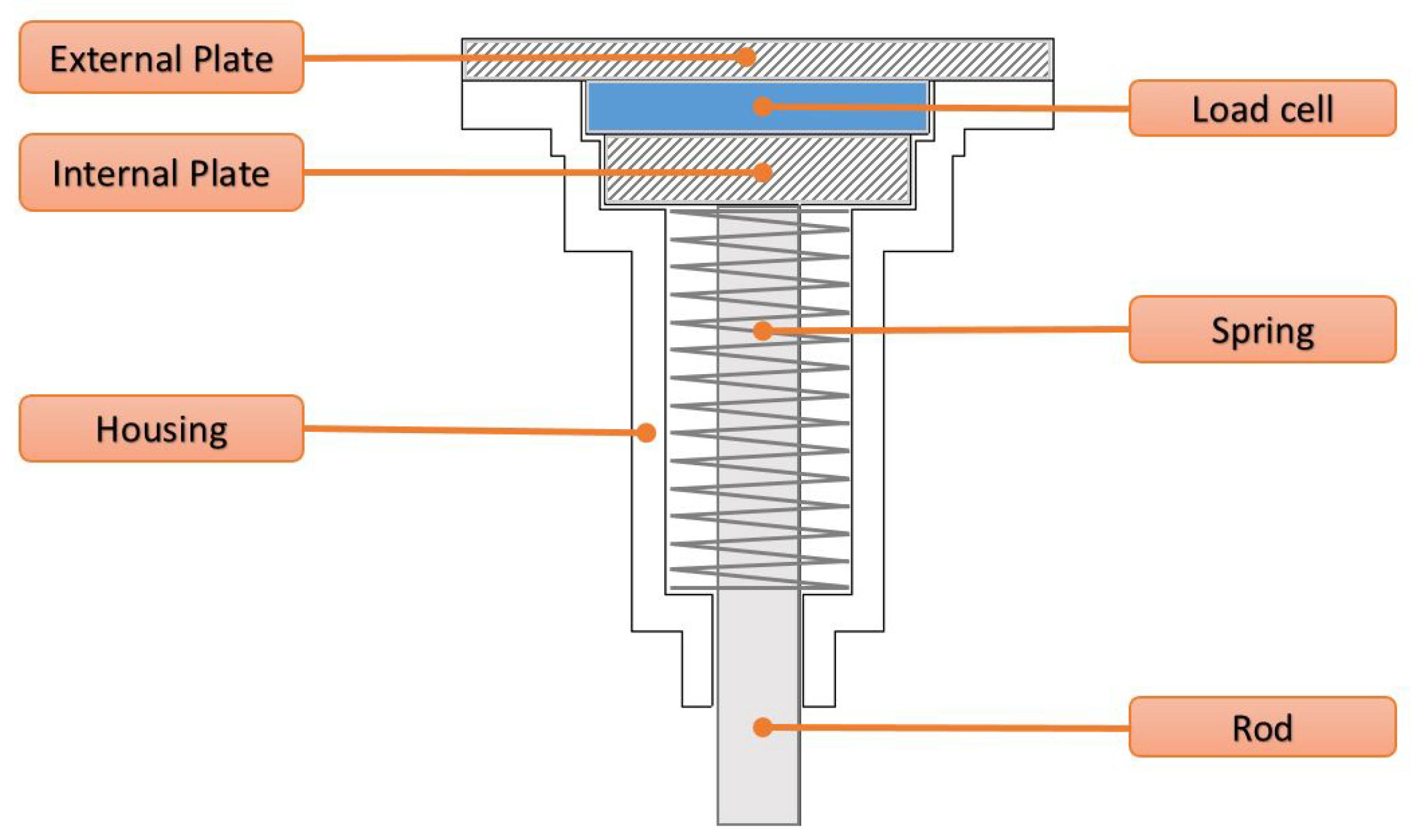
The load cell assembly, shown in Figure 3, was previously developed for other projects where accurate force measurements were required [85]. The assembly consists of a spring and two plates that enclose the sensor. This setup acts as a preload mechanism for the sensor because in the first 10% of its full scale of operation, the sensor exhibits nonlinear behaviour. Therefore, with this simple mechanism, the operation of the sensor will always be in the linear region. Moreover, the load cell was selected on the basis of a first series of experimental stem cutting tests of the plant of interest. In these first experiments, it was detected that the crop of interest needed a shear force of approximately 90–200 N, so a 500 N load cell was selected. However, the design of the load cell housing allows it to be easily exchanged for one with a lower or higher value.
3.1.2. Modified Warner–Bratzler Device
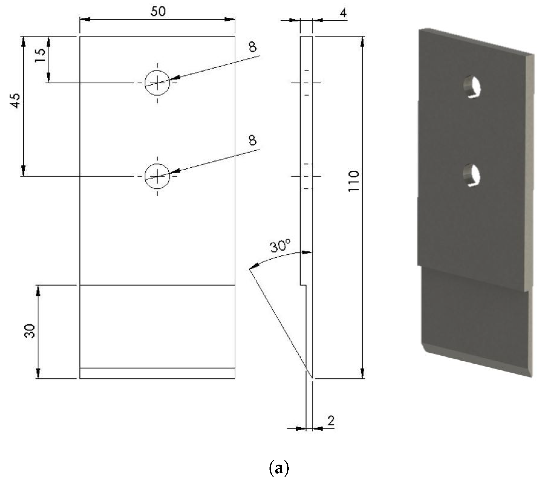
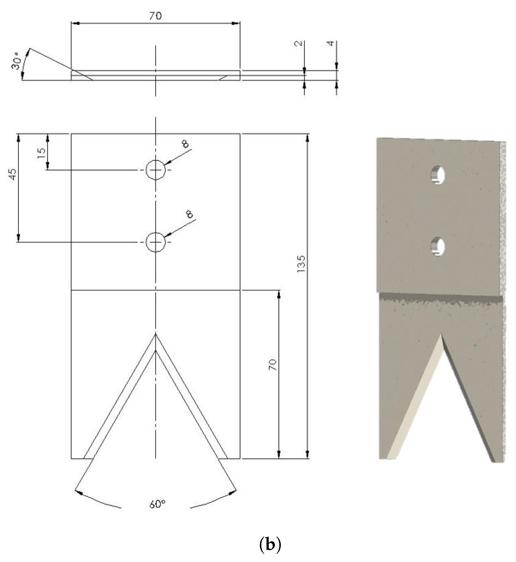
All the experiments mentioned in the research background section are valid to obtain the shear characteristics of the materials, as long as they comply with the characteristics of accuracy, repeatability and reproducibility. However, the modified Warner–Bratzler method will be use due to its easy implementation and to the fact that it is treated extensively and in detail in the literature. In this modification, devised in [75,80], the blades were sharpened so that they could cut different plant materials. In this case, two types of blades were used: (i) a V-blade with an angle of 60 degrees, which, as described in the Warner–Bratzler experiment, was used for cylindrical materials and (ii) a straight blade, which was used to test the influence of the blade on the experiment. Both blades had a thickness of 0.002 m, were made of stainless steel and had an edge of 30 degrees, which produced energy-efficient cuts [60,86]. In addition, the blades were smooth and not serrated, as it has been shown in several experiments that this type of blade is better for cutting stalks containing high levels of moisture [87]. The blades are shown in Figure 4.
3.1.3. Motor-Encoder
The testing machine was powered by an Escap 35 NT motor, which included an Escap R40 with a 134:1 ratio gearbox. The position of the mobile base (see Figure 2) was obtained by converting the readings of the three high-resolution optical channels of the Escap E9-0500 encoder through the various gearboxes of the mechanical press and the motor gearbox.
3.2. Acquisition, Control and Data Processing
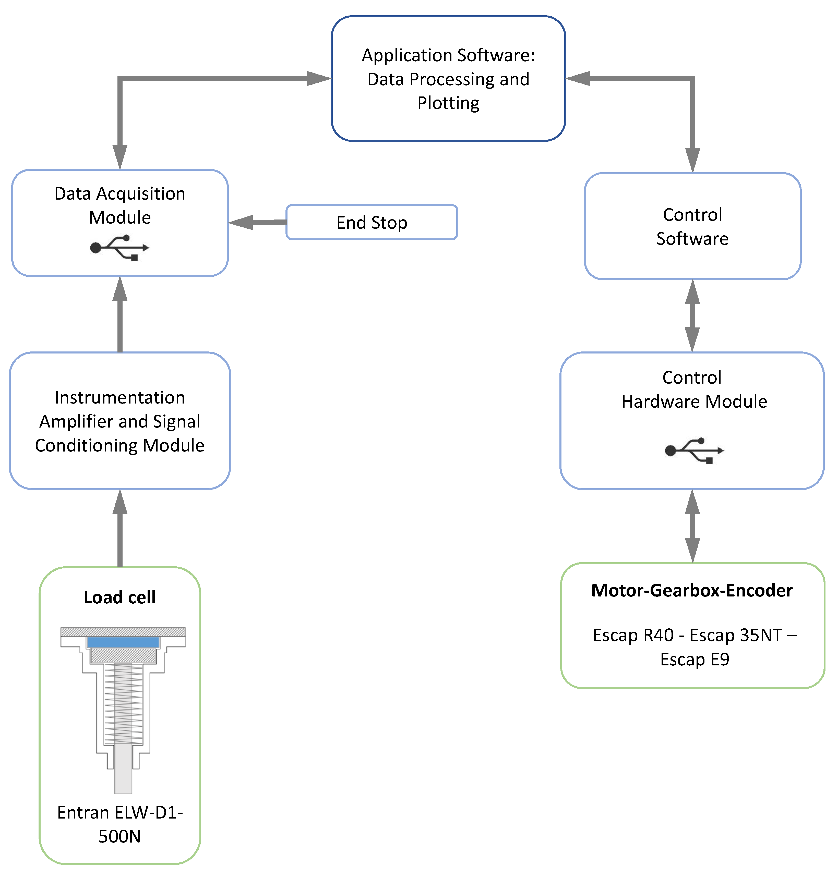
Data acquisition was performed by an electronic signal conditioning module and a data acquisition (DAQ) module, and the processing of the acquired data was carried out by means of mathematical software and control software. A diagram of the process is illustrated in Figure 5.
The data acquisition process begins with the initialization of the application software, which calls the control software and the USB data acquisition module. The control software initializes the motor continuously and reads its encoder. The number of turns given by the motor is then counted by the encoder and read by the control, which converts the number of turns of the motor into the real displacement of the base, taking into account the different mechanical reductions involved. This displacement information is sent from the control hardware to the software application; on the other hand, the data acquisition module reads the force sensor measurements and sends them to the software application. All this information is represented in quasi-real time by means of three graphs: position-time, force-time and force-position. Both the encoder and load cell readings end automatically when the blade passes completely through the diameter of the peduncle since the acquisition module detects when the blade presses the end stop (see Figure 2). Then, the acquisition module sends this information to the software application, which order to stop both readings, finishing the measurement process.
4. Empirical Modelling
4.1. Methodology
The material testing machine, the acquisition module and the processing data system generate the following graphs: force vs. time, position vs. time and force vs. position. These graphs correspond with the shear characteristics of the aubergine stalks, where several intrinsic factors, such as the moisture content and the average size, affect the shape of the curves. With the main purpose of describing a detailed profile of the shear mechanical properties of the aubergine stalks, the equations and the methods used are presented in detail below.
The goal is to find the maximum load, which determines the fracture of the peduncle; the ultimate shear stress; and the specific energy consumed for each peduncle.
First, the maximum load () is indicated in the manifold force-position graphs of the tested peduncles. Given that a stalk is cut by a single blade in the press, the ultimate shear stress is then calculated by means of the following formula:
where is the ultimate shear stress (Pa), is the peak shear force (N), and is the cut cross-sectional area of the peduncle (m). Since can approach a circle, it is calculated as follows:
where is the diameter of the peduncle (m).
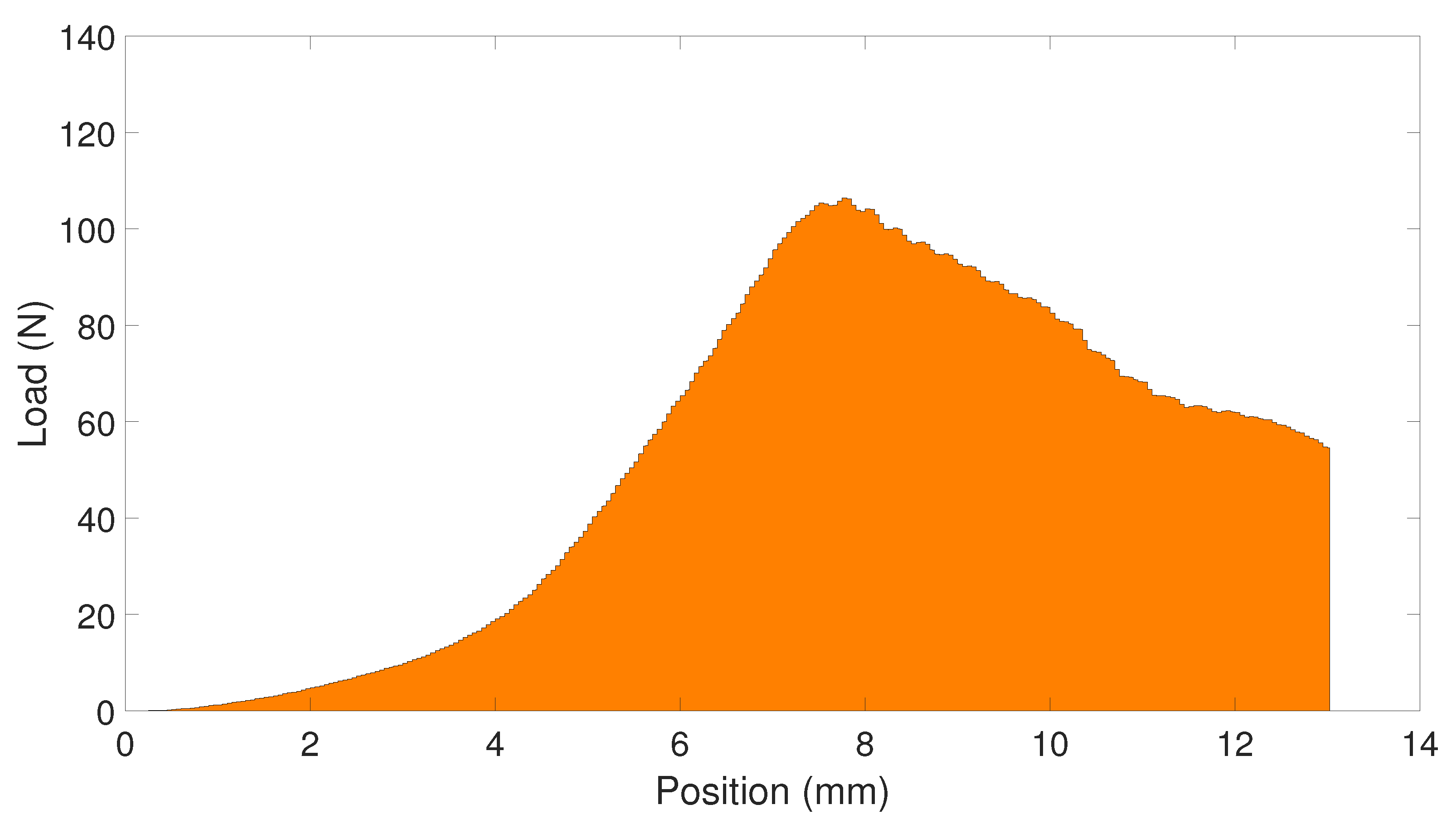
The trapezoidal rule is then used to calculate the integral of the curve obtained in the force-position graph, thus obtaining the area equivalent to the total cutting energy () of an aubergine peduncle (see Figure 6). Furthermore, in this same step, the energy consumed () due to friction is calculated from the integral of the curve in the force-position graph, and this energy represents that of the press acting without any peduncle located in it. Consequently,
where: is the shear energy consumed (J) and is the specific energy consumed ().
The methods, rules, and postulates applied in the shear experiments, i.e., the methodology, was a compendium of those used in various articles devoted to this type of plant study [59,61,62]. First, aubergines were transported to a laboratory, where room conditions were maintained at a temperature of approximately 24 C and a relative humidity of approximately 60%. The samples were gradually desiccated during storage to resemble the processing conditions. The peduncle specimens were numbered and identified by the size and weight of the aubergines to which they belonged.
The experiments were carried out in four series of 11 samples, where healthy aubergines without any observable damage were selected. The first stalk of each series was subjected to a moisture test, where a KERN halogen moisture analyser was used in a 100 C process with a period of 10 min. The moisture content of the prepared peduncles ranged from 85 to 84% w.b. during the tests. The next 10 samples were used for the cutting experiment. Before cutting the peduncles, the entire aubergine, including the peduncle, was weighed, and then both were weighed separately. All the measurements were made using a KERN scale (accuracy kg). After a whole series was weighed, the minor and major dimensions of the peduncle diameters were measured using a digital calliper (accuracy m), and the samples were deposited on an identification sheet for further experimentation using the cutting machine.
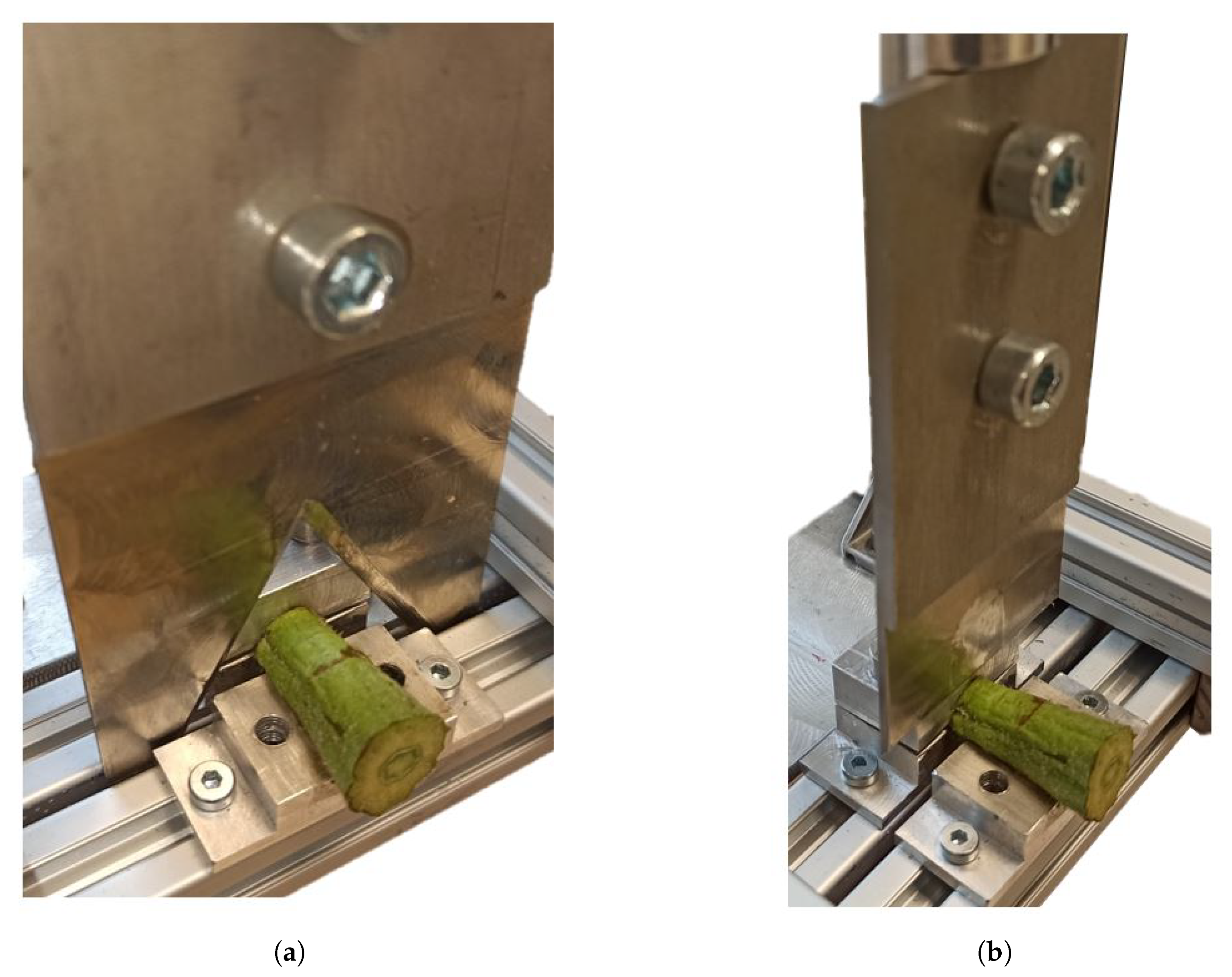
The samples were attached to the press by means of a pair of clamps, although in some cases where the dimensions of their diameters were loose in the locking jaws, parts of other peduncles were also used for the fastening. The specimens were prepared in the press by tightening the locking jaws. They were tightened in such a way that the deformation effects were minimized since they are undesirable in this experiment [88]. The fastening of the samples is shown in Figure 7.
Subsequently, a visual check of the press was performed, ensuring that the Warner–Bratzler blade was not damaged and that the press was in good condition. A no-load test was then performed, where the friction of the blade with the elements was measured by the force sensor.
An experiment began by adjusting the blade closer to the peduncle and moving the peduncle at a constant speed of 2.1 × 10 m/s. Similar speeds can be seen in shear experiments in the literature [75,89]. The various states observed during the cutting process were annotated, and the force-time graph was verified to check if it was in line with expectations. Throughout the experiments, the residues from the old specimens in the locking jaws and the blade were cleaned, and a visual inspection of the press and the cutter was performed after every five specimen cuts. The instructions outlined in this paragraph were repeated with the straight blade.
4.2. Sample Collection and Preparation
Among the technical characteristics of aubergine plants, the following can be highlighted. Aubergines grow into tall, widespread, bushy plants that can reach 0.5 to 2.5 m in height. The fruit has a shiny black colour that serves as an indicator of maturity and suitability for harvesting, with lengths ranging from 0.04 or 0.05 m to more than 0.30 m depending on the variety [48]. For these experiments, aubergines were collected from a field in Almeria (Spain) (364427.4 N 24903.2 W) in the first week of February. These specimens were cut with the entire stem and stored in a warehouse to reduce moisture loss. Two days after the cutting, the shear experiments were carried out for a whole day to avoid significant differences in the humidity of the samples between series. In this sense, the experiments were carried out in two groups: Group A involved measuring and weighing the peduncles and aubergines, and group B involved carrying out the cutting experiments. The start and end times and the peduncle humidity details of the series are shown in Table 2.
For the experiments, all peduncles were cut to a certain length, and a total of 40 samples were selected for testing. The specifications are described in Figure 8 and Table 3. A series of tested samples is shown in Figure 9c,d.
The morphology of aubergine peduncles, and more specifically, the Thelma variety (Figure 9a), is heterogeneous. As shown in Figure 9b, three large parts can be distinguished. First, the cortex represents approximately 15% of the peduncle section and is characterized by being rough to the touch and by the presence of some thorns. Second, an intermediate zone with a softer consistency represents approximately 45% of the peduncle section. Finally, a hard core with a fibrous sensation represents approximately 40% of the peduncle section.
5. Results and Discussion
5.1. Blade Effects in the Experimental Test
In [75,90], the authors described the various regions that can be observed when cutting fibrous biomass, as well as the deviations that can be produced by the material properties, the orientation with respect to the blade, the number of stems tested and the blade edge. Although these authors provided a description for forage plants, the sources of deviation cited can serve to explain cutting experiments in other types of plants.
During the cutting tests performed for the samples of aubergine peduncles, where the notched and straight blade geometries were used, it was possible to identify several distinct regions in the observed force-position curves (shown in Figure 10, Figure 11 and Figure 12), and these regions differed for each blade and explained the nature of the cutting process. Therefore, the actions performed and the results observed during the experiments with each blade are described below.
5.1.1. Cutting Experiments with the V-Notched Blade
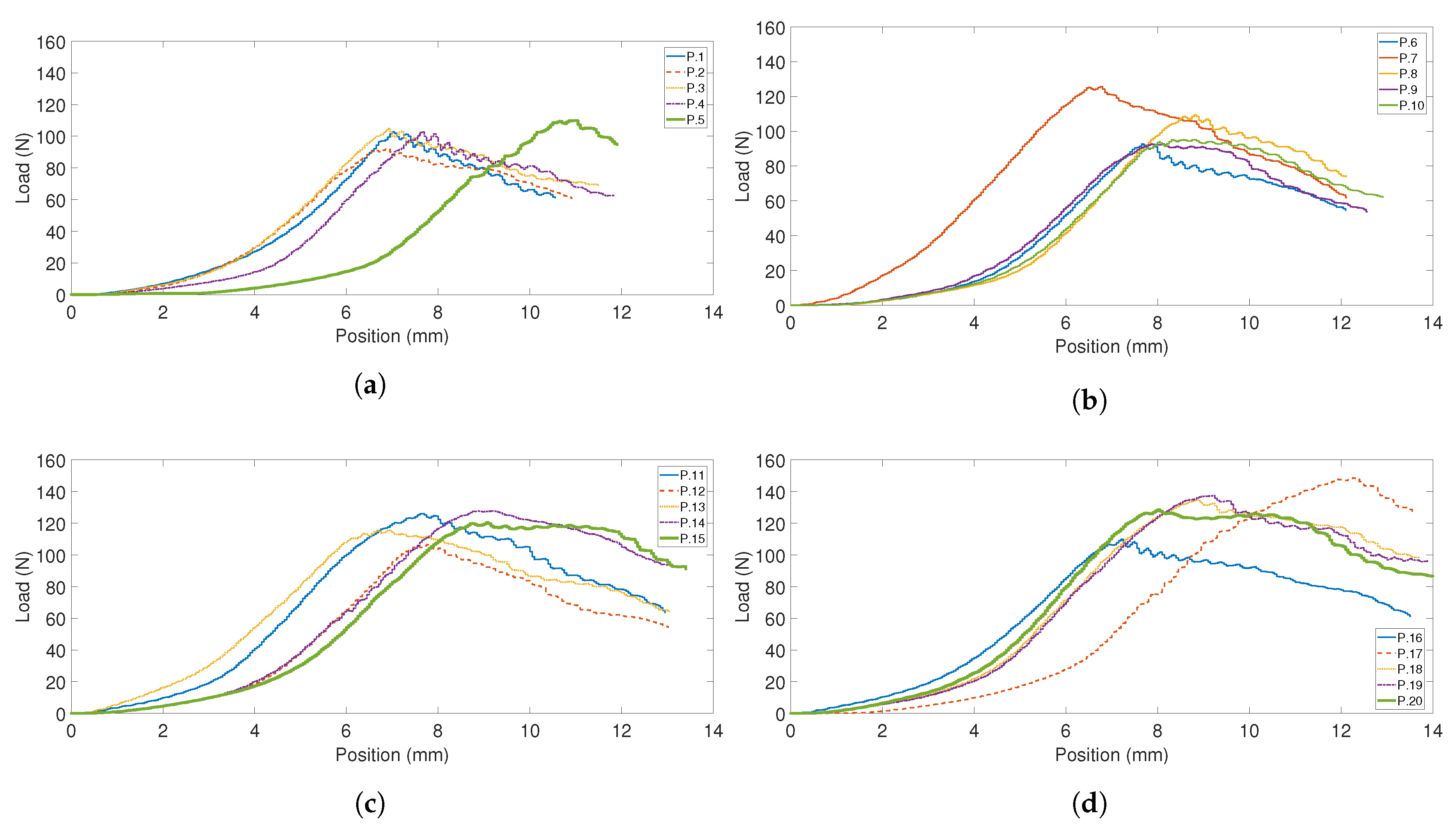
First, the blade was brought closer to the peduncle and then compressed by the load distributed along the V-shaped edge of the blade to a level of failure (i.e., when the blade penetrates the stalk). The initial cut of the blade penetrates and makes the first cut perfectly fit the circular profile of the peduncle, cutting the crust and a few fibres in the first intermediate zone almost without force. This can be observed in the graphs in Figure 10 in the slope before the peak load. Just before the maximum load, it can be seen how the slope of the curve decreases because the outer skin of the core is being compressed. At that point, the peak load is reached and is almost constant through the core zone. Finally, in the second intermediate zone, the skin and several uncut core fibres were compressed and cut, and the end of the peduncle cut was reached. The decrease in the slope of the curve can be seen in Figure 10. As reported by other authors [75], the final stage ends with residual loads that correspond to the resistance offered by the combination of wedging, gripping, and rubbing of the cut stalk surfaces on the descending blade. These parasitic forces, which occur to a greater extent at the end of the cut, were partially eliminated because once the blade had cut the entire stem, the force sensor no longer provided a measurement. However, it is practically impossible to avoid these types of forces during cutting, so they were present throughout the cutting operation.
5.1.2. Cutting Experiments with the Straight Blade
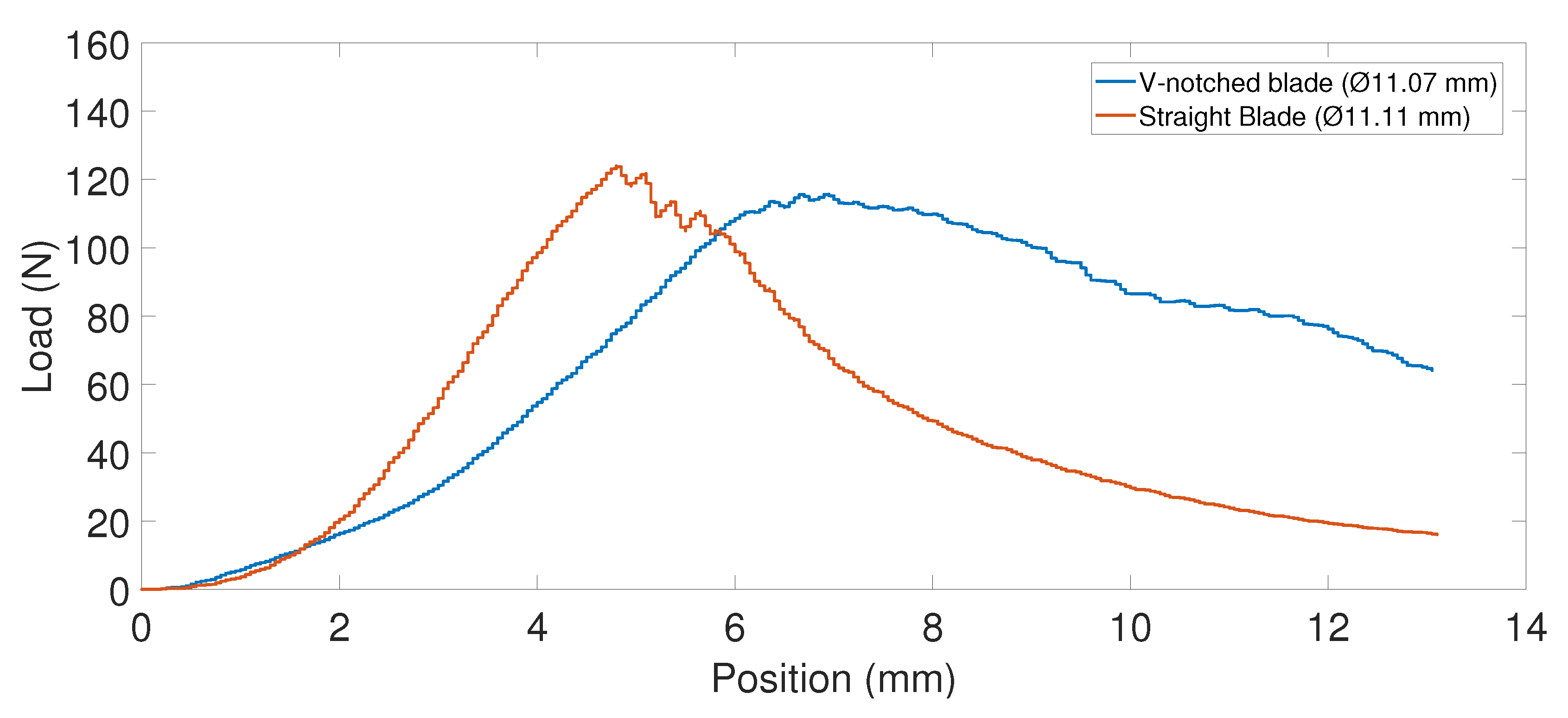
First, the blade was brought closer to the peduncle, compressing it to the level of failure. In contrast to the previous case, the initial cut of the straight blade penetrates and makes the first cut by compressing the crust and some fibres in the first intermediate zone with remarkable force. This initial cut can be observed in the steepness of the slope at the beginning of the curve (shown in Figure 11).
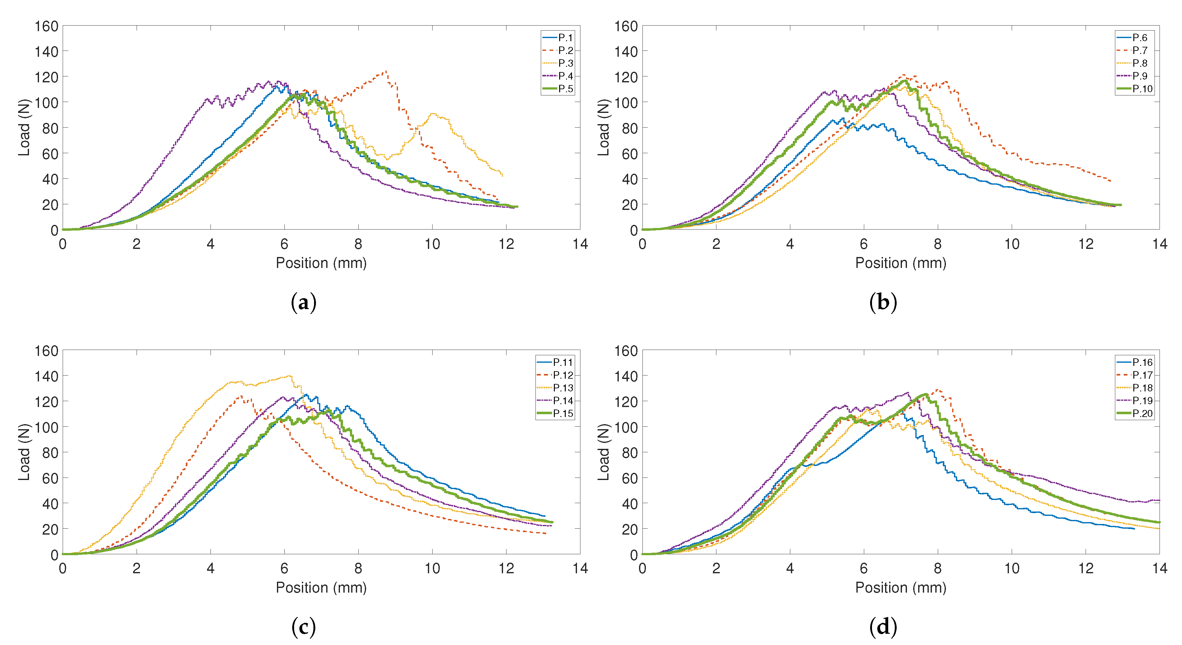
The second-highest peak load occurs when the blade passes through the first core layer and continues with almost the same force for a couple of millimetres, where the blade compresses the core zone fibres. Then, the first maximum load is reached. Finally, in this stage, a few deformations were observed in all the samples that were cut with the straight blade. These deformations affected the cutting of the second intermediate zone, the crust and several uncut core fibres until the end of the peduncle was reached. This can be observed in the downward slope of the curve in Figure 12. As experienced with the other blade, the final stage ends with residual loads that correspond to the resistance offered by the combination of wedging, gripping, and rubbing of the cut stalk surfaces on the descending blade.
5.2. Mechanical Cutting Parameters for Aubergine Stalks
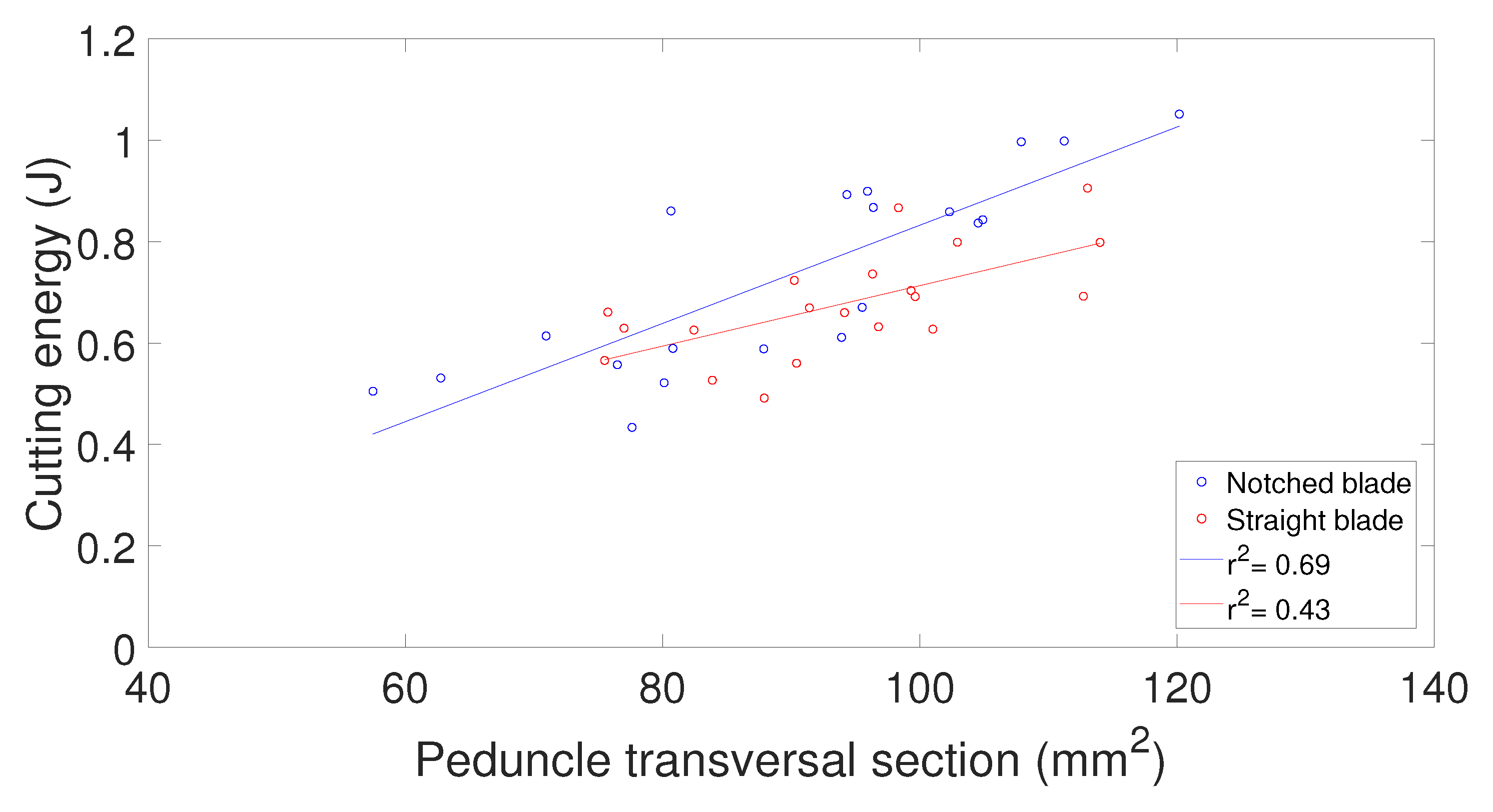
In the experiments with the notched blade, there is a positive Pearson correlation coefficient of r = 0.7 for the maximum cutting force and of r = 0.8 for the relative cutting energy in front of the peduncle section. The coefficient of determination (), shown in Figure 13, is = 0.69 for the V-notched blade and = 0.43 for the straight blade. As reported by other research [46], the V-notched blade provides better correlations between values than the straight blade. The non-perfect could be explained by factors such as the density of the core area of each peduncle and its diameter, rather than the total diameter, i.e., the sum of the core area, the intermediate part and the crust. It is also worth noting, however, that this coefficient can be affected by factors such as deformation, which was prevalent in the case of the flat blade.
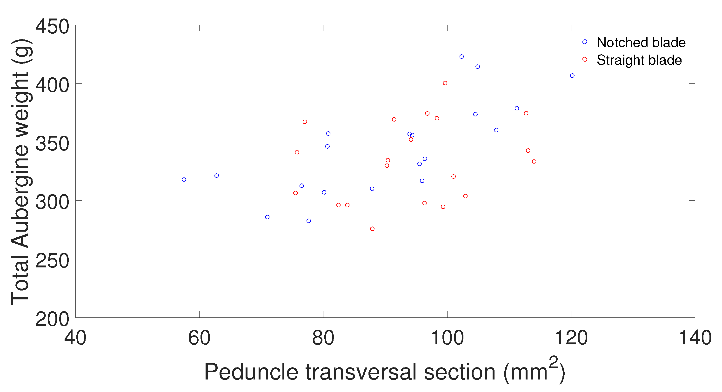
For the notched and straight blades, the dimensional parameters of peduncles were almost the same, as shown in Figure 8. Although the peak force, cutting energy and stress parameters were similar between the two blades (see Table 4 and Table 5), the force-position characteristics varied for each blade. This variation is given by the fitting of the blade to the peduncle, with the V-shaped blade being the one that best distributes the force. This distribution can be seen in the smoothness of the force-position curve, shown in Figure 10. In contrast, in the straight blade curve, there are 2 peaks of maximum load, the last one due to deformation, as shown in Figure 12.
Of the 40 aubergine stems that were cut, the peak load values ranged from 87 N to 148 N with an average of 115 N, and these values are lower than the values reported for hemp stems (67–555 N) [87] and higher than those for maize stalks (23–80 N) [60], grasses (11.2–60 N) [91], and pyrethrum flowers (2.5–2.9 N) [92]. In terms of the ultimate shear stress (peak load/area), the mean values ranged from 1.0 to 1.8 MPa, and these values are close to those for corn stalks (2.01–2.11 MPa) [46] and for sunflower stalks (0.95–1.5 MPa) [93]. Regarding the specific cutting energy, the values ranged from 5.6 to 10.7 kJ/m and are similar to the values reported for other crops such as cornstalks (11.3–23.5 kJ/m for the internode and 8.6–14.0 kJ/m for the node) [75], (15.7–43.1 kJ/m) [94], grasses and alfalfa (3.9–4.9 kJ/m) [91], and sunflower stalks (1.5–11.0 kJ/m) [93]. These results confirm that the obtained values are in line with the ranges reported in general. All values are shown the Table 4 for the notched blade and in Table 5 for the straight blade.
With these results, an estimation can be made of what the application of the proposed design criterion represents in the aubergine harvesting process. The average yield of an aubergine crop is in the range of 4 to 15 kg/m, with a more frequent value of 10.50 kg/m [95]. Assuming that the average weight of tested aubergines is 0.340 kg and the average cutting energy for each aubergine is 0.73 J for the V-notched blade, the estimated cutting energy is 0.225 MJ/ha. Assuming that the manual harvesting of aubergines involves 7161 h/ha and 14,036 MJ/ha, and that it represents the 5% of the total production energy [96], the proposed design criteria for robotic cutting gripper can contribute significantly to improve the efficient of the harvesting process. Furthermore, the proposed criterion can serve as a guide to evaluate the efficiency of these designs, and as a mechanism to standardize the measure of the key parameters that affect the cutting process within the harvesting operation.
6. Design of Robotic Harvesting Tools
For the cutting of peduncles, there are several techniques that can be classified into two groups: (i) techniques based on the bending characteristics of the stalk, such as the bending force, bending stress and Young’s modulus, and (ii) techniques based on the shear characteristics, such as the shear force, shear strength and shear energy.
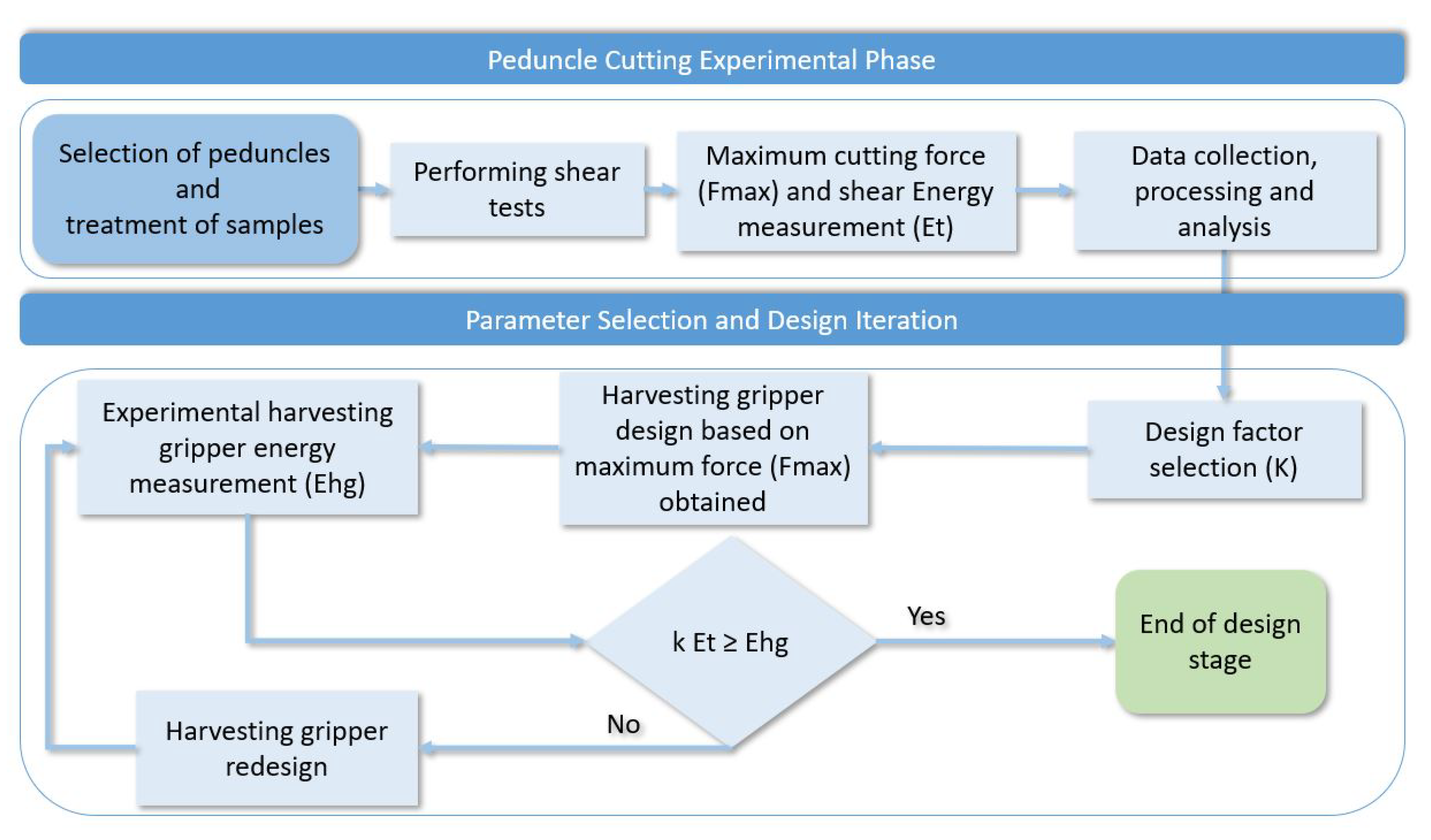
The protocol used in this article brings together the knowledge and methods used by other authors for the study of the shear characteristics in agricultural applications. Furthermore, this protocol provides a design guide for cutting tools based on energy consumption minimization. Additionally, the protocol can be used as a classification framework based on its suitability for the crop to be harvested and can contribute to the advancement of the state of art in achieving more energy-efficient devices and classification methods. To summarize, this methodology is shown in Figure 14 and listed as follows:
- First, the process begins with the definition of the fruit to be harvested. In this part, there must be certainty that the fruit cannot be harvested by another of the methods mentioned above, such as the indirect movement of the fruit through the plant or the direct movement of the fruit by pulling, bending or twisting. It has to be the case that the crop can be harvested by the cutting method. In this case, apart from the energy criterion, other criteria, such as not damaging the fruit or a post-processing criterion to remove the stalk, must be taken into account [20].
- Then, in the second step, relevant samples of the fruit peduncles are obtained, which must be collected and tested within a short period of time after they have been cut since it has been demonstrated that the moisture content directly affects the values obtained in the test, such as the peak load and the cutting energy [87].
- In the third step, the experiment of cutting the peduncles is carried out, following the protocol detailed in this article, which includes the experiences learned by other authors.
- In the fourth step, the maximum forces are obtained along with the shear energy, which can be estimated by applying the obtained measurements in the equations. After analysis of the data and verification of their homogeneity, a mathematical model can be found to fit the data obtained. Typically, the relationship between the shear energy and a section of the peduncle can provide an almost linear model. The task to select a design factor (k) applied to the minimum cutting energy () for the efficient design of the cutting tool will be left to the designer. An indicative criterion for the selection of this parameter is the one used in those plants in which the stems can be divided into nodes and internodes. In these cases, the design of the tool must be based on the maximum force () required to cut the largest node portion of the plant. This approach is reported to work well for the entire stalk, as it already includes the variation arising from the material (internode) and the size [75].
- Once the experimental model of the cutting gripper is obtained, the energy consumption of the harvesting gripper () is measured and compared with obtained from the performed cutting experiments; it is known that can never be reached because the harvesting tool will be affected by factors such as friction between parts, the efficiency of the mechanism, and the performance of the electric motor or other electronic elements used to control it. If is greater than , the cutting gripper must be redesigned, taking into account the factors mentioned above.
- When a balance between the energy consumed and the cut-off energy determined by the design factor is achieved, the design stage based on the energy criteria is completed.
7. Conclusions
In industry, process optimization and energy efficiency are continuously improved. However, these types of improvement processes are rarely implemented in the primary sector, perhaps due to the inherent complexity of natural environments, which are unstructured and highly variable, as in agriculture, for example. This article has attempted to address the efficiency of the agricultural sector, and more specifically, the tasks of fruit harvesting. As already mentioned, numerous authors have promoted and researched problems of energy reduction in cutting tools in the agricultural sector, reporting several successful cases. For this reason, this article has incorporated this relatively recent knowledge to formulate a design proposal for cutting tools based on an energy criterion. In particular, this study has focused on the cutting tools that are implemented in harvesting robots since until now, there has been no design methodology for these types of tools. The proposed design criterion can be crucial for reducing the energy consumption of these tools and for increasing the efficiency of harvesting robots.
On the other hand, this study could be extended to achieve an enhanced implementation of a perception system. If more experiments are carried out with other plants, an artificial vision system could be trained through machine learning algorithms to realistically estimate the energy consumption required for the harvesting of each plant, taking into account the relationship between the weight of the aubergines, and the force and energy necessary for their harvest. Even the operation of the cutting gripper could be adapted to the energy requirements of each particular stalk, further reducing the energy consumption of the entire system. The proposed approach can also contribute to realistically estimating the environmental footprint. In the manufacturing sector, the environmental footprint is calculated based on average energy consumption and is reflected in environmental impact databases. As a result, these values are highly inaccurate and give distorted figures to life cycle assessment practitioners [53].
The protocol formulated in this article is intended to be a guide for the designers of robotic cutting end-effectors and cutting tools for harvesting, as well as a way to determine the suitability of the cutting tools for the plants to be harvested. Since there is a need to increase studies in this field for the diverse plants that can be harvested by a peduncle cutting method, this article describes in detail the experiments carried out on aubergines, as well as a compilation of the methods used by other authors, so that these experiments can be replicated for other types of plants to characterize them for optimal harvesting. In future work, we will also consider the study of the shear energy with different moisture content of the peduncles.
Author Contributions
Conceptualization, E.N. and R.F.; methodology, E.N. and P.G.-d.-S.; software, D.S.; validation, E.N., and M.A.; formal analysis E.N.; investigation, E.N.; writing—original draft preparation, E.N.; writing—review and editing R.F. and P.G.-d.-S.; visualization, E.N.; supervision R.F.; funding acquisition R.F. and P.G.-d.-S. All authors have read and agreed to the published version of the manuscript.
Funding
The research leading to these results has received funding from: 1. FEDER/Ministerio de Ciencia, Innovación y Universidades—Agencia Estatal de Investigación/Proyecto ROBOCROP (DPI2017-84253-C2-1-R); 2. RoboCity2030-DIH-CM, Madrid Robotics Digital Innovation Hub, S2018/NMT-4331, funded by “Programas de Actividades I+D en la Comunidad de Madrid” and cofunded by Structural Funds of the EU; 3. Ayudas de la Consejería de Educación, Juventud y Deporte de la Comunidad de Madrid para la promoción de empleo joven e implantación de la Garantía Juvenil en I+D+i en el marco de la Orden 1669/2018, en el Subprograma Estatal de Incorporación, del Programa Estatal de Promoción del Talento y su Empleabilidad en I+D+I.
Conflicts of Interest
The authors declare no conflict of interest.
References
- United Nations. World Population Prospects: The 2015 Revision, Key Findings and Advance Tables; United Nations, Department of Economic and Social Affairs, PD (Population Division): New York, NY, USA, 2015. [Google Scholar]
- Nagasaka, Y.; Umeda, N.; Kanetai, Y.; Taniwaki, K.; Sasaki, Y. Autonomous guidance for rice transplanting using global positioning and gyroscopes. Comput. Electron. Agric. 2004, 43, 223–234. [Google Scholar] [CrossRef]
- Iida, M.; Suguri, M.; Uchida, R.; Ishibashi, M.; Kurita, H.; Won-Jae, C.; Masuda, R.; Ohdoi, K. Advanced harvesting system by using a combine robot. IFAC Proc. Vol. 2013, 46, 40–44. [Google Scholar] [CrossRef]
- Noguchi, N.; Will, J.; Reid, J.; Zhang, Q. Development of a master–slave robot system for farm operations. Comput. Electron. Agric. 2004, 44, 1–19. [Google Scholar] [CrossRef]
- Zhang, Z.; Noguchi, N.; Ishii, K.; Yang, L.; Zhang, C. Development of a robot combine harvester for wheat and paddy harvesting. IFAC Proc. Vol. 2013, 46, 45–48. [Google Scholar] [CrossRef]
- Blanes, C.; Mellado, M.; Ortiz, C.; Valera, A. Technologies for robot grippers in pick and place operations for fresh fruits and vegetables. Span. J. Agric. Res. 2011, 9, 1130–1141. [Google Scholar] [CrossRef]
- Xia, C.; Wang, L.; Chung, B.K.; Lee, J.M. In situ 3D segmentation of individual plant leaves using a RGB-D camera for agricultural automation. Sensors 2015, 15, 20463–20479. [Google Scholar] [CrossRef]
- Font, D.; Pallejà, T.; Tresanchez, M.; Runcan, D.; Moreno, J.; Martínez, D.; Teixidó, M.; Palacín, J. A proposal for automatic fruit harvesting by combining a low cost stereovision camera and a robotic arm. Sensors 2014, 14, 11557–11579. [Google Scholar] [CrossRef] [Green Version]
- Mehta, S.; Burks, T. Vision-based control of robotic manipulator for citrus harvesting. Comput. Electron. Agric. 2014, 102, 146–158. [Google Scholar] [CrossRef]
- Cubero, S.; Diago, M.P.; Blasco, J.; Tardáguila, J.; Millán, B.; Aleixos, N. A new method for pedicel/peduncle detection and size assessment of grapevine berries and other fruits by image analysis. Biosyst. Eng. 2014, 117, 62–72. [Google Scholar] [CrossRef] [Green Version]
- Sepúlveda, D.; Fernández, R.; Navas, E.; González-de Santos, P.; Armada, M. ROS Framework for Perception and Dual-Arm Manipulation in Unstructured Environments. In Iberian Robotics Conference; Springer: Berlin/Heidelberg, Germany, 2019; pp. 137–147. [Google Scholar]
- Tabile, R.A.; Godoy, E.P.; Pereira, R.R.; Tangerino, G.T.; Porto, A.J.; Inamasu, R.Y. Design and development of the architecture of an agricultural mobile robot. Eng. Agric. 2011, 31, 130–142. [Google Scholar] [CrossRef]
- Agostini, A.; Alenya, G.; Fischbach, A.; Scharr, H.; Woergoetter, F.; Torras, C. A cognitive architecture for automatic gardening. Comput. Electron. Agric. 2017, 138, 69–79. [Google Scholar] [CrossRef] [Green Version]
- Zion, B.; Mann, M.; Levin, D.; Shilo, A.; Rubinstein, D.; Shmulevich, I. Harvest-order planning for a multiarm robotic harvester. Comput. Electron. Agric. 2014, 103, 75–81. [Google Scholar] [CrossRef]
- Xiong, Y.; Ge, Y.; Grimstad, L.; From, P.J. An autonomous strawberry-harvesting robot: Design, development, integration, and field evaluation. J. Field Robot. 2020, 37, 202–224. [Google Scholar] [CrossRef] [Green Version]
- Hua, Y.; Zhang, N.; Yuan, X.; Quan, L.; Yang, J.; Nagasaka, K.; Zhou, X.G. Recent Advances in Intelligent Automated Fruit Harvesting Robots. Open Agric. J. 2019, 13, 101–106. [Google Scholar] [CrossRef] [Green Version]
- Nasini, L.; Proietti, P. Olive harvesting. In The Extra-Virgin Olive Oil Handbook; Wiley: Hoboken, NJ, USA, 2014; pp. 87–105. [Google Scholar]
- Polat, R.; Guner, M.; Dursun, E.; Erdogan, D.; Gezer, I.; Bilim, H.C. Mechanical harvesting of almond with an inertia type limb shaker. Asian J. Plant Sci. 2007, 6, 528–532. [Google Scholar]
- Polat, R.; Gezer, I.; Guner, M.; Dursun, E.; Erdogan, D.; Bilim, H.C. Mechanical harvesting of pistachio nuts. J. Food Eng. 2007, 79, 1131–1135. [Google Scholar] [CrossRef]
- Dimeas, F.; Sako, D.V.; Moulianitis, V.C.; Aspragathos, N.A. Design and fuzzy control of a robotic gripper for efficient strawberry harvesting. Robotica 2015, 33, 1085–1098. [Google Scholar] [CrossRef]
- Hayashi, S.; Shigematsu, K.; Yamamoto, S.; Kobayashi, K.; Kohno, Y.; Kamata, J.; Kurita, M. Evaluation of a strawberry-harvesting robot in a field test. Biosyst. Eng. 2010, 105, 160–171. [Google Scholar] [CrossRef]
- De-An, Z.; Jidong, L.; Wei, J.; Ying, Z.; Yu, C. Design and control of an apple harvesting robot. Biosyst. Eng. 2011, 110, 112–122. [Google Scholar] [CrossRef]
- Baeten, J.; Donné, K.; Boedrij, S.; Beckers, W.; Claesen, E. Autonomous fruit picking machine: A robotic apple harvester. In Field and Service Robotics; Springer: Berlin/Heidelberg, Germany, 2008; pp. 531–539. [Google Scholar]
- Li, J.; Karkee, M.; Zhang, Q.; Xiao, K.; Feng, T. Characterizing apple picking patterns for robotic harvesting. Comput. Electron. Agric. 2016, 127, 633–640. [Google Scholar] [CrossRef] [Green Version]
- Davidson, J.R.; Silwal, A.; Hohimer, C.J.; Karkee, M.; Mo, C.; Zhang, Q. Proof-of-concept of a robotic apple harvester. In Proceedings of the 2016 IEEE/RSJ International Conference on Intelligent Robots and Systems (IROS), Daejeon, Korea, 9–14 October 2016; pp. 634–639. [Google Scholar]
- Monta, M.; Kondo, N.; Ting, K.C. End-effectors for tomato harvesting robot. In Artificial Intelligence for Biology and Agriculture; Springer: Berlin/Heidelberg, Germany, 1998; pp. 1–25. [Google Scholar]
- Yaguchi, H.; Nagahama, K.; Hasegawa, T.; Inaba, M. Development of an autonomous tomato harvesting robot with rotational plucking gripper. In Proceedings of the 2016 IEEE/RSJ International Conference on Intelligent Robots and Systems (IROS), Daejeon, Korea, 9–14 October 2016; pp. 652–657. [Google Scholar]
- Li, Z.; Li, P.; Yang, H.; Wang, Y. Stability tests of two-finger tomato grasping for harvesting robots. Biosyst. Eng. 2013, 116, 163–170. [Google Scholar] [CrossRef]
- Zhao, Y.; Gong, L.; Liu, C.; Huang, Y. Dual-arm robot design and testing for harvesting tomato in greenhouse. IFAC-Pap. Online 2016, 49, 161–165. [Google Scholar] [CrossRef]
- Hayashi, S.; Ganno, K.; Ishii, Y.; Tanaka, I. Robotic harvesting system for eggplants. Jpn. Agric. Res. Q. JARQ 2002, 36, 163–168. [Google Scholar] [CrossRef] [Green Version]
- Edan, Y.; Rogozin, D.; Flash, T.; Miles, G.E. Robotic melon harvesting. IEEE Trans. Robot. Autom. 2000, 16, 831–835. [Google Scholar] [CrossRef]
- Muscato, G.; Prestifilippo, M.; Abbate, N.; Rizzuto, I. A prototype of an orange picking robot: past history, the new robot and experimental results. Ind. Robot Int. J. 2005, 32, 128–138. [Google Scholar] [CrossRef]
- Van Henten, E.J.; Hemming, J.; Van Tuijl, B.; Kornet, J.; Meuleman, J.; Bontsema, J.; Van Os, E. An autonomous robot for harvesting cucumbers in greenhouses. Auton. Robots 2002, 13, 241–258. [Google Scholar] [CrossRef]
- Hemming, J.; Bac, C.; van Tuijl, B.; Barth, R.; Bontsema, J.; Pekkeriet, E.; Van Henten, E. A Robot for Harvesting Sweet-Pepper in Greenhouses. In Proceedings of the International Conference of Agricultural Engineering (AgEng), Zurich, Switzerland, 6–9 July 2014. [Google Scholar]
- Bac, C.W.; Hemming, J.; Van Tuijl, B.; Barth, R.; Wais, E.; van Henten, E.J. Performance evaluation of a harvesting robot for sweet pepper. J. Field Robot. 2017, 34, 1123–1139. [Google Scholar] [CrossRef]
- Lehnert, C.; English, A.; McCool, C.; Tow, A.W.; Perez, T. Autonomous sweet pepper harvesting for protected cropping systems. IEEE Robot. Autom. Lett. 2017, 2, 872–879. [Google Scholar] [CrossRef] [Green Version]
- Ceccarelli, M.; Figliolini, G.; Ottaviano, E.; Mata, A.S.; Criado, E.J. Designing a robotic gripper for harvesting horticulture products. Robotica 2000, 18, 105–111. [Google Scholar] [CrossRef] [Green Version]
- Van Henten, E.; Van Tuijl, B.V.; Hemming, J.; Kornet, J.; Bontsema, J.; Van Os, E. Field test of an autonomous cucumber picking robot. Biosyst. Eng. 2003, 86, 305–313. [Google Scholar]
- Mattiazzo, G.; Mauro, S.; Raparelli, T.; Velardocchia, M. A fuzzy controlled pneumatic gripper for asparagus harvesting. Control Eng. Pract. 1995, 3, 1563–1570. [Google Scholar] [CrossRef]
- Irie, N.; Taguchi, N.; Horie, T.; Ishimatsu, T. Asparagus harvesting robot coordinated with 3-D vision sensor. In Proceedings of the 2009 IEEE International Conference on Industrial Technology, Gippsland, VIC, Australia, 10–13 February 2009. [Google Scholar]
- Chatzimichali, A.P.; Georgilas, I.P.; Tourassis, V.D. Design of an advanced prototype robot for white asparagus harvesting. In Proceedings of the 2009 IEEE/ASME International Conference on Advanced Intelligent Mechatronics, Singapore, 14–17 July 2009; pp. 887–892. [Google Scholar]
- Glaus, H. Electric Scissors. U.S. Patent 3,631,596, 4 January 1972. [Google Scholar]
- Pellenc, R. Trigger-Operated Portable Electric Tool. U.S. Patent 8,813,370, 26 August 2014. [Google Scholar]
- Schmid, A.E. Power Pruning Shears. U.S. Patent 3,178,816, 20 April 1965. [Google Scholar]
- Dongdong, D. Research on mechanics properties of crop stalks: A review. Int. J. Agric. Biol. Eng. 2016, 9, 10–19. [Google Scholar]
- Womac, A.; Yu, M.; Igathinathane, C.; Ye, P.; Hayes, D.; Narayan, S.; Sokhansanj, S.; Wright, L. Shearing characteristics of biomass for size reduction. ASAE Pap. 2005, 56058, 2–8. [Google Scholar]
- Gan, H.; Mathanker, S.; Momin, M.A.; Kuhns, B.; Stoffel, N.; Hansen, A.; Grift, T. Effects of three cutting blade designs on energy consumption during mowing-conditioning of Miscanthus Giganteus. Biomass Bioenergy 2018, 109, 166–171. [Google Scholar] [CrossRef]
- Rubatzky, V.E.; Yamaguchi, M. World Vegetables: Principles, Production, and Nutritive Values; Springer: Berlin/Heidelberg, Germany, 2012. [Google Scholar]
- Hayashi, S.; Ganno, K.; Ishii, Y.; Tanaka, I. Development of a harvesting end-effector for eggplants [Solanum melongena]. J. Soc. High Technol. Agric. 2001, 13, 97–103. [Google Scholar] [CrossRef]
- Wan, I.W.; Kit, W.; Awal, M. Design and Development of Eggplant Harvester for Gantry System. Pertanika J. Sci. Technol. 2010, 18, 231–242. [Google Scholar]
- Kara, S. Life cycle engineering: Applying life cycle knowledge to engineering solutions. CIRP J. Manuf. Sci. Technol. 2009, 4, 213. [Google Scholar] [CrossRef]
- Anderberg, S.; Kara, S.; Beno, T. Impact of energy efficiency on computer numerically controlled machining. Proc. Inst. Mech. Eng. Part B J. Eng. Manuf. 2010, 224, 531–541. [Google Scholar] [CrossRef]
- Li, W.; Kara, S. An empirical model for predicting energy consumption of manufacturing processes: A case of turning process. Proc. Inst. Mech. Eng. Part B J. Eng. Manuf. 2011, 225, 1636–1646. [Google Scholar] [CrossRef]
- Wang, L.; Meng, Y.; Ji, W.; Liu, X. Cutting energy consumption modelling for prismatic machining features. Int. J. Adv. Manuf. Technol. 2019, 103, 1657–1667. [Google Scholar] [CrossRef]
- Herrmann, C.; Thiede, S.; Zein, A.; Ihlenfeldt, S.; Blau, P. Energy efficiency of machine tools: extending the perspective. In Proceedings of the 42nd CIRP International Conference on Manufacturing Systems, Grenoble, France, 3–5 June 2009; pp. 3–5. [Google Scholar]
- Campatelli, G.; Lorenzini, L.; Scippa, A. Optimization of process parameters using a response surface method for minimizing power consumption in the milling of carbon steel. J. Clean. Prod. 2014, 66, 309–316. [Google Scholar] [CrossRef]
- Mou, X.; Liu, Q.; Ou, Y.; Wang, M.; Song, J. Mechanical properties of the leaf sheath of sugarcane. Trans. ASABE 2013, 56, 801–812. [Google Scholar]
- Tavakoli, H.; Mohtasebi, S.; Jafari, A. Comparison of mechanical properties of wheat and barley straw. Agric. Eng. Int. CIGR Ejournal 2008, 10, 1–9. [Google Scholar]
- Yu, M.; Cannayen, I.; Hendrickson, J.; Sanderson, M.; Liebig, M. Mechanical shear and tensile properties of selected biomass stems. Trans. ASABE 2014, 57, 1231–1242. [Google Scholar]
- Prasad, J.; Gupta, C. Mechanical properties of maize stalk as related to harvesting. J. Agric. Eng. Res. 1975, 20, 79–87. [Google Scholar] [CrossRef]
- Kronbergs, E. Mechanical strength testing of stalk materials and compacting energy evaluation. Ind. Crops Prod. 2000, 11, 211–216. [Google Scholar] [CrossRef]
- Yu, M.; Womac, A.; Igathinathane, C.; Ayers, P.; Buschermohle, M. Switchgrass ultimate stresses at typical biomass conditions available for processing. Biomass Bioenergy 2006, 30, 214–219. [Google Scholar] [CrossRef]
- O’dogherty, M.; Huber, J.; Dyson, J.; Marshall, C. A study of the physical and mechanical properties of wheat straw. J. Agric. Eng. Res. 1995, 62, 133–142. [Google Scholar] [CrossRef]
- Sharma, B.; Jones, C.; Khanchi, A. Tensile strength and shear strength of switchgrass before and after frost. Biol. Eng. Trans. 2011, 4, 43–54. [Google Scholar] [CrossRef]
- Tavakoli, H.; Mohtasebi, S.S.; Jafari, A. Physical and mechanical properties of wheat straw as influenced by moisture content. Int. Agrophys. 2009, 23, 175–181. [Google Scholar]
- Esehaghbeygi, A.; Hoseinzadeh, B.; Masoumi, A. Effects of moisture content and urea fertilizer on bending and shearing properties of canola stem. Appl. Eng. Agric. 2009, 25, 947–951. [Google Scholar] [CrossRef]
- Shahbazi, F.; Galedar, M.N.; Taheri-Garavand, A.; Mohtasebi, S. Physical properties of safflower stalk. Int. Agrophys. 2011, 25, 281–286. [Google Scholar]
- Khan, M.M.R.; Chen, Y.; Belsham, T.; Laguë, C.; Landry, H.; Peng, Q.; Zhong, W. Fineness and tensile properties of hemp (Cannabis sativa L.) fibres. Biosyst. Eng. 2011, 108, 9–17. [Google Scholar] [CrossRef]
- Ma, S.; Karkee, M.; Scharf, P.A.; Zhang, Q. Sugarcane harvester technology: A critical overview. Appl. Eng. Agric. 2014, 30, 727–739. [Google Scholar]
- Song, R.; Li, S.; Sun, X.H.; Ma, F.L.; Hu, S.S. Experimental research on influence factor of cutting-force of sugarcane harvest machine. J. Agric. Mech. Res. 2006, 7, 128–132. [Google Scholar]
- Gupta, C.; Oduori, M. Design of the revolving knife-type sugarcane basecutter. Trans. ASAE 1994, 35, 1747–1752. [Google Scholar] [CrossRef]
- Mello, R.D.C.; Harris, H. Cane damage and mass losses for conventional and serrated basecutter blades. In Proceedings of the 2000 Conference of the Australian Society of Sugar Cane Technologists, Bundaberg, QLD, Australia, 2–5 May 2000; pp. 84–91. [Google Scholar]
- Mello, R.D.C.; Harris, H. Angled and serrated blades reduce damage, force and energy for a harvester basecutter. In Proceedings of the Australian Society of Sugar Cane Technologists, Brisbane, QLD, Australia, 17–21 September 2001; pp. 1212–1218. [Google Scholar]
- Mello, R.D.C.; Harris, H. Performance of basecutter of sugarcane harvester with angled and serrated blades. Rev. Bras. Eng. Agric. Ambient. 2004, 7, 355–358. [Google Scholar] [CrossRef] [Green Version]
- Igathinathane, C.; Womac, A.; Sokhansanj, S. Corn stalk orientation effect on mechanical cutting. Biosyst. Eng. 2010, 107, 97–106. [Google Scholar] [CrossRef]
- Kovács, Á.; Kerényi, G. Physical characteristics and mechanical behaviour of maize stalks for machine development. Int. Agrophys. 2019, 33, 427–436. [Google Scholar] [CrossRef]
- Azadbakht, M.; Asl, A.R.; Zahedi, K. Energy Requirement for Cutting Corn Stalks (Single Cross 704 Var.). Int. J. Biol. Food Vet. Agric. Eng. 2014, 8, 471–474. [Google Scholar]
- Dange, A.R.; Thakare, S.; Rao, I.B. Cutting energy and force as required for Pigeon pea stems. J. Agric. Technol. 2011, 7, 1485–1493. [Google Scholar]
- Yiljep, Y.; Mohammed, U. Effect of knife velocity on cutting energy and efficiency during impact cutting of sorghum stalk. Agric. Eng. Int. CIGR J. 2005, VII, 1–10. [Google Scholar]
- Igathinathane, C.; Pordesimo, L.; Schilling, M.; Columbus, E. Fast and simple measurement of cutting energy requirement of plant stalk and prediction model development. Ind. Crops Prod. 2011, 33, 518–523. [Google Scholar] [CrossRef]
- Warner, K. Progress report of the mechanical test for tenderness of meat. J. Anim. Sci. 1929, 1929, 114–116. [Google Scholar] [CrossRef]
- Warner, K. Adventures in testing meat for tenderness. Proc. Recip. Meat Conf. 1952, 5, 156–160. [Google Scholar]
- Bratzler, L.J. Measuring the Tenderness of Meat by Means of a Mechanical Shear; Kansas State College: Manhattan, KS, USA, 1932. [Google Scholar]
- Bratzler, L. Determining the tenderness of meat by use of the Warner–Bratzler method. Proc. Recip. Meat Conf. 1949, 2, 117–121. [Google Scholar]
- Fernández, R.; Montes, H.; Armada, M. Intelligent multisensor prodder for training operators in humanitarian demining. Sensors 2016, 16, 965. [Google Scholar] [CrossRef] [Green Version]
- Visvanathan, R.; Sreenarayanan, V.; Swaminathan, K. Effect of knife angle and velocity on the energy required to cut cassava tubers. J. Agric. Eng. Res. 1996, 64, 99–102. [Google Scholar] [CrossRef]
- Chen, Y.; Gratton, J.L.; Liu, J. Power requirements of hemp cutting and conditioning. Biosyst. Eng. 2004, 87, 417–424. [Google Scholar] [CrossRef]
- Dowgiallo, A. Cutting force of fibrous materials. J. Food Eng. 2005, 66, 57–61. [Google Scholar] [CrossRef]
- Liu, Q.; Mathanker, S.; Zhang, Q.; Hansen, A.C. Biomechanical properties of miscanthus stems. Trans. ASABE 2012, 55, 1125–1131. [Google Scholar] [CrossRef]
- Chancellor, W. Energy requirement for cutting forage. Agric. Eng. 1958, 39, 633–640. [Google Scholar]
- McRandal, D.; McNulty, P. Mechanical and physical properties of grasses. Trans. ASAE 1980, 23, 816–821. [Google Scholar] [CrossRef]
- Khazaei, J.; Rabani, H.; Ebadi, A.; Golbabaei, F. Determining the shear strength and picking force of pyrethrum flower. Iran. J. Agric. Sci. 2002, 33, 433–444. [Google Scholar]
- Ince, A.; Uğurluay, S.; Güzel, E.; Özcan, M. Bending and shearing characteristics of sunflower stalk residue. Biosyst. Eng. 2005, 92, 175–181. [Google Scholar] [CrossRef]
- Akritidis, C. The mechanical characteristics of maize stalks in relation to the characteristics of cutting blade. J. Agric. Eng. Res. 1974, 19, 1–12. [Google Scholar] [CrossRef]
- Flores, E.D. Energy use and CO2 emissions of eggplant production in the Philippines. Agric. Eng. Int. CIGR J. 2016, 18, 138–148. [Google Scholar]
- Canakci, M.; Akinci, I. Energy use pattern analyses of greenhouse vegetable production. Energy 2006, 31, 1243–1256. [Google Scholar] [CrossRef]
Figure 1.
Types of cutting experiments found in the literature.

Figure 2.
Diagram of the shear test devices.

Figure 3.
Detailed drawing of the custom-made load cell installation.

Figure 4.
(a) Modified Warner–Bratzler straight blade. (b) Modified Warner–Bratzler V-notched blade. All dimensions are in mm.
Figure 4.
(a) Modified Warner–Bratzler straight blade. (b) Modified Warner–Bratzler V-notched blade. All dimensions are in mm.


Figure 5.
Diagram of the main components of the cutting test-bed.

Figure 6.
Cutting Energy E1.

Figure 7.
Both blades with a peduncle in a half-mounted clamp. (a) Notched blade; (b) straight blade.
Figure 7.
Both blades with a peduncle in a half-mounted clamp. (a) Notched blade; (b) straight blade.

Figure 8.
Characterization of the peduncles based on the section and total weight of the aubergine. The peduncles are also divided according to the type of blade with which the shear test was performed.
Figure 8.
Characterization of the peduncles based on the section and total weight of the aubergine. The peduncles are also divided according to the type of blade with which the shear test was performed.

Figure 9.
Aubergine cutting experiment. (a) Aubergines. (b) Peduncle transverse section view. (c) Series before the cutting experiment. (d) Series after the cutting experiment.
Figure 9.
Aubergine cutting experiment. (a) Aubergines. (b) Peduncle transverse section view. (c) Series before the cutting experiment. (d) Series after the cutting experiment.

Figure 10.
Position-load for a notched blade. Graphs are ordered from lower to higher diameter sizes and P indicates the sample number. (a) First quarter of peduncles tested. Sample diameters ranging from 8.56 to 9.95 mm. (b) Second quarter of peduncles tested. Sample diameters ranging from 10.11 to 10.94 mm. (c) Third quarter of peduncles tested. Sample diameters ranging from 10.96 to 11.42 mm. (d) Fourth quarter of peduncles tested. Sample diameters ranging from 11.55 to 12.37 mm.

Figure 11.
Difference in steepness of the slope between the V-notched and straight blades.

Figure 12.
Position-load for a straight blade. Graphs are ordered from lower to higher diameter sizes and P indicates the sample number. (a) First quarter of peduncles tested . Sample diameters ranging from 9.82 to 10.34 mm. (b) Second quarter of peduncles tested. Sample diameters ranging from 10.58 to 10.96 mm. (c) Third quarter of peduncles tested. Sample diameters ranging from 11.07 to 11.27 mm. (d) Fourth quarter of peduncles tested. Sample diameters ranging from 11.35 to 12.05 mm.

Figure 13.
Cutting energy for the notched and straight blades.

Figure 14.
Procedure for parameter selection.


Table 1.
Main technical specifications of the compression load cell.
| Non-linearity | ±1% |
| Hysteresis | ±1% |
| Thermal Zero Shift | ±2.5 mV/50 C |
| Thermal Sensitivity Shif | ±2.5%/50 C |
| Deflection at “FS” | <0.013 mm nom. |
| Operating Temperature | (−40 to 120) C |
| Thickness | 3.81 mm |
| Diameter | 25.4 mm |
Table 2.
Specifications of cutting experiments.
| Experiment Statistics | Series 1 | Series 2 | Series 3 | Series 4 |
|---|---|---|---|---|
| Start time | 9:13 | 10:14 | 14:47 | 15:24 |
| End time | 10:40 | 11:41 | 15:46 | 16:47 |
| Humidity (%) | 85.43 | 84.62 | 84.47 | 84.16 |
Table 3.
Specifications of the 40 aubergine peduncles tested.
| Statistics | Major Diameter (mm) | Minor Diameter (mm) | Sectional Area (×10m) |
|---|---|---|---|
| Mean | 11.14 | 10.47 | 9.21 |
| Maximum | 12.44 | 12.34 | 12.01 |
| Minimum | 8.86 | 8.26 | 5.75 |
| SD | 0.87 | 0.87 | 1.43 |
| CV(%) | 7.83 | 8.31 | 15.50 |
Table 4.
Results for 20 aubergine peduncles tested with the notched blade.
| Statistics | Peak Load (N) | Ultimate Shear Stress (MPa) | Shear Energy (J) | Specific Shear Energy (J/m) |
|---|---|---|---|---|
| Mean | 114.14 | 1.29 | 0.73 | 8135.92 |
| Maximum | 148.69 | 1.78 | 1.051 | 10,671.19 |
| Minimum | 92.045 | 1.01 | 0.433 | 5586.14 |
| SD | 16.39 | 0.20 | 0.19 | 1261.08 |
| CV (%) | 14.36 | 15.31 | 26.07 | 15.50 |
Table 5.
Results for 20 aubergine peduncles tested with the straight blade.
| Statistics | Peak Load (N) | Ultimate Shear Stress (MPa) | Shear Energy (J) | Specific Shear Energy (J/m) |
|---|---|---|---|---|
| Mean | 117.00 | 1.25 | 0.678 | 7226.91 |
| Maximum | 139.98 | 1.64 | 0.905 | 8814.99 |
| Minimum | 87.44 | 0.99 | 0.491 | 5590.92 |
| SD | 11.50 | 0.16 | 0.11 | 891.77 |
| CV (%) | 9.83 | 12.65 | 15.79 | 12.34 |
© 2020 by the authors. Licensee MDPI, Basel, Switzerland. This article is an open access article distributed under the terms and conditions of the Creative Commons Attribution (CC BY) license (http://creativecommons.org/licenses/by/4.0/).
Share and Cite
MDPI and ACS Style
Navas, E.; Fernandez, R.; Sepúlveda, D.; Armada, M.; Gonzalez-de-Santos, P. A Design Criterion Based on Shear Energy Consumption for Robotic Harvesting Tools. Agronomy 2020, 10, 734. https://doi.org/10.3390/agronomy10050734
AMA Style
Navas E, Fernandez R, Sepúlveda D, Armada M, Gonzalez-de-Santos P. A Design Criterion Based on Shear Energy Consumption for Robotic Harvesting Tools. Agronomy. 2020; 10(5):734. https://doi.org/10.3390/agronomy10050734
Chicago/Turabian StyleNavas, Eduardo, Roemi Fernandez, Delia Sepúlveda, Manuel Armada, and Pablo Gonzalez-de-Santos. 2020. "A Design Criterion Based on Shear Energy Consumption for Robotic Harvesting Tools" Agronomy 10, no. 5: 734. https://doi.org/10.3390/agronomy10050734
Note that from the first issue of 2016, this journal uses article numbers instead of page numbers. See further details here.