
An Optimal Fuzzy Logic-Based Energy Management Strategy for a Fuel Cell/Battery Hybrid Power Unmanned Aerial Vehicle


1
Electrical Engineering Department of the Automation School, Northwestern Polytechnic University, Xi’an 710072, China
2
Key Laboratory of Aircraft Electric Propulsion Technology, Ministry of Industry and Information Technology of China, Xi’an 710072, China
*
Author to whom correspondence should be addressed.
Aerospace 2022, 9(2), 115; https://doi.org/10.3390/aerospace9020115
Submission received: 13 December 2021
/
Revised: 4 February 2022
/
Accepted: 7 February 2022
/
Published: 21 February 2022
(This article belongs to the Special Issue Fuel Cell Aircraft)
Abstract
:With the development of high-altitude and long-endurance unmanned aerial vehicles (UAVs), optimization of the coordinated energy dispatch of UAVs’ energy management systems has become a key target in the research of electric UAVs. Several different energy management strategies are proposed herein for improving the overall efficiency and fuel economy of fuel cell/battery hybrid electric power systems (HEPS) of UAVs. A rule-based (RB) energy management strategy is designed as a baseline for comparison with other strategies. An energy management strategy (EMS) based on fuzzy logic (FL) for HEPS is presented. Compared with classical rule-based strategies, the fuzzy logic control has better robustness to power fluctuations in the UAV. However, the proposed FL strategy has an inherent defect: the optimization performances will be determined by the heuristic method and the past experiences of designers to a great extent rather than a specific cost function of the algorithm itself. Thus, the paper puts forward an improved fuzzy logic-based strategy that uses particle swarm optimization (PSO) to track the optimal thresholds of membership functions, and the equivalent hydrogen consumption minimization is considered as the objective function. Using a typical 30 min UAV mission profile, all the proposed EMS were verified by simulations and rapid controller prototype (RCP) experiments. Comprehensive comparisons and analysis are presented by evaluating hydrogen consumption, system efficiency and voltage bus stability. The results show that the PSO-FL algorithm can further improve fuel economy and achieve superior overall dynamic performance when controlling a UAV’s fuel-cell powertrain.
1. Introduction
Fuel cells are suitable for the power demands of long-endurance UAVs due to their high conversion efficiency and high energy density. Meanwhile, fuel cells can generate electrical energy with near-zero pollution, less noise and less heat compared with conventional combustion engine driven generators. Therefore, the developments in fuel-cell technology align with tendencies toward green aviation and electrically propelled aircraft [1,2,3]. Furthermore, a fuel-cell-powered system hybridized with batteries and ultra-capacitors (UC), which have high power densities, could compensate for the deficient transient performance of fuel cells themselves, and this system could improve the holistic mobility and reliability of UAVs. There has been a multitude of studies on fuel-cell UAVs in universities and polytechnics in the last few decades. For example, the 500 W fuel-cell-powered UAV from Georgia University in 2006; the Ion Tiger UAV with a world record endurance of 48 h in 2013 and EAV-2—which combines solar and fuel cells together—from the Korea Aerospace Research Institute (KARI) [4,5,6].
There is no doubt that a well-designed EMS is indispensable for HEPS based on fuel cells, as an EMS can guarantee each power source operates with efficiency while meeting the load power requirements [7]. Nowadays, a host of EMSs for fuel-cell HEPS can be seen in the literature, especially in the fields of micro-grids (MG) [8,9], hybrid electrical vehicles (HEV) [10,11,12,13,14,15,16], electric ships [17,18], more electric aircraft (MEA) [19,20,21,22] and electrical propulsion aircraft and UAVs [23,24,25,26,27,28,29]. EMSs are represented by popular online control methods, such as rule-based control [19,28,29,30], fuzzy-based control [9,23,31,32,33,34], model predictive control [12,15,17,35,36,37] and fuzzy logic model predictive control [13]; and other optimization-based methods, such as convex optimization [14], dynamic programming (DP) [24] and neural network (NN) methods [10]. Deep reinforcement learning (DRL) [18] algorithms are known as offline algorithms with great optimization performance.
The driving modes of the vehicle and the UAV can be divided into two modes: manual operation and automatic operation. Pay attention to the difference in the propulsion power demand characteristics of the two. The vehicle’s power demand changes frequently and the change range is large, and the peak power demand of the UAV is relatively smooth in different mission stages. The power requirement of the UAV during the climbing phase is much greater than the power requirement during the cruising phase. Nonetheless, the current research on UAV hybrid power systems’ EMSs focuses more on software simulations and ground demonstrations than actual flight. Due to the complexity of UAV systems, their aerodynamics and their flight control laws being strictly limited [4,6], only a few simple energy management strategies have been successfully implemented. To design an effective energy management system for a fuel-cell drone, there are two main challenges for the control system:
- (i)
- How can the operating efficiency of the fuel-cell system be improved in various flight scenarios to keep the battery power within the allowable range and reduce the pressure of the fuel-cell system?
- (ii)
- Under the constraints of the CPU and memory configuration of the onboard controller, how can the computational burden of the nonlinear energy management optimization problem be reduced so that the controller can respond in real-time to the power demand of the UAV?
A comparative study of EMS for a hybrid emergency power system of MEA was performed by Motapon S N et al., who also proposed five kinds of EMS, which were compared by evaluating hydrogen consumption economy, overall efficiency, and fuel-cell lifecycle [19,20]. At present, RB-based control has become a widely-applied strategy for UAVs in virtue of its safety and reliability. A Savvaris et al. [27] achieved a hard-in-the-loop experiment for a fuel-cell-battery-powered UAV with a four-state RB strategy. B Lee et al. [28] proposed an active power management algorithm with six control sectors, and then demonstrated its utility in 3.8 h of mission profiling. A UAV with hybrid solar and hydrogen energy was designed by Liu et al. [29]. It can fly for more than 20 h based on RB control.
Unfortunately, many studies concentrated more on the verification of a certain EMS for a fixed flight profile, while other evaluation criteria were left out of consideration. Some global optimization methods need a complex optimization model and solver, which can increase the computational burden of the EMS in question, and divergence of such algorithms is also a problem [13,14]. Although DRL and NNs can perform very well [10,18], real flight data sets are still needed. Acquiring these data sets can be costly and risky, but the lack of such data sets also makes EMSs relying on deep learning perform poorly in real-time. Thus, the EMSs for electric propulsion UAVs must have the trade-off of optimal energy distribution and real-time computation efficiency.
Fuzzy logic control is another classical real-time EMS, and its calculation process is independent of an accurate system energy optimization model. This characteristic makes FL control very suitable for a nonlinear power system, such as that of an HEV or UAV [23,31,32,34]. Zhang X et al. put forward an online fuzzy logic strategy for a fuel-cell/battery UAV and then demonstrated its effectiveness on a ground test-bench [23]. The experimental results show that the hydrogen consumption under FL control is lower than typical RB control. It is worthwhile mentioning that the thresholds designed in RB control and FL control all depend on the designer’s own knowledge for system operation, and the optimization results of which can be approximately optimal in theory based on rule and experience. In order to make up for this drawback, other advanced meta-heuristic algorithms have been proposed in fuel-cell HEPS, such as Artificial Bee Colony (ABC), the Grey Wolf Optimization (GWO), the cuckoo search, Salp swarm optimization, and the mine blast algorithm [22,38], to find the optimal energy distribution or split for load demand. Furthermore, wavelet transform [39] and genetic algorithms [40] can optimize inputs of energy management controller with frequency decoupling and adjust the thresholds of membership functions combined with fuzzy logic control, respectively. However, these studies are focused on the MEA’s APU or emergency power system, where the power load profile is only 30 min and the pulse load or slow variation load was considered, and the effects of flight dynamic load’s variation on EMS of aircraft or UAV are not analyzed in detail.
This research paper aims to design a high-performance online EMS for a fuel-cell/battery hybrid power system of the UAV. A ground test bench of HEPS for UAV based on RCP is built firstly, followed by presenting a five-state RB strategy and a fuzzy logic strategy. Then a global-based PSO algorithm is designed to track the optimal thresholds of original membership functions of fuzzy logic control, which regards minimization of hydrogen consumption and less dynamic burden of power sources as the optimization objective and redefines a kind of equivalent hydrogen consumption with a penalty function. Finally, a thirty-minute dynamic mission profile of UAV has been tested on the real-time RCP platform to demonstrate the feasibility and effectiveness of the proposed energy management strategies for UAV.
Within this article, the main contributions to the research field can be shown as follows.
- (i)
- According to the power demand of fuel-cell powered UAV during different flight phases in which the propulsion load power of UAV was analyzed with the flight dynamics, the EMS based on the PSO-based optimal fuzzy logic methods is presented in this paper. The simulation model of the hybrid power system was built with the EMS system. The comprehensive model that allows the fuel-cell hybrid power system to use different energy management strategies is developed in this paper.
- (ii)
- The integrating testing bench for the EMS in the fuel cell UAV is built with the rapid controller prototype simulation platform, which can be used to design different EMS strategies. Several different EMS strategies such as the rule-based, fuzzy logic, and PSO-fuzzy logic control are compared based on simulation and experimental results for the UAV power system, and some conclusions were obtained to verify the theoretical analysis.
- (iii)
- A comprehensive computational and experimental analysis highlights the scalability of the proposed algorithm to UAV hybrid power systems. The results of our analysis illustrate the performance of the algorithm of PSO-fuzzy logic, the benefits of the energy management strategy, and the advantages of flexible demands to extend the flight range of UAVs.
This paper is organized as follows. The modeling and description of the HEPS of UAV are shown in Section 2. Section 3 presents three implemented EMS in detail, including illustrations of the design flow and principles. A comprehensive analysis and comparison from simulation and experiment results is shown in Section 4. Finally, Section 5 provides the conclusions, and the future scope and potentials of the current research are elaborated in this section.
2. Problem Formulation of Energy Management for HEPS of UAV
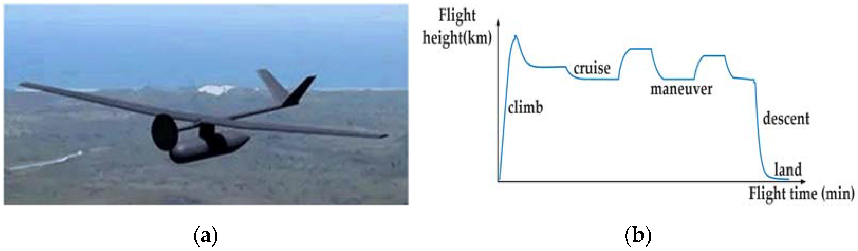
The paper conducts EMS research on a certain type of single-propeller and fixed-wing fuel cell/battery UAV. The effect drawing of the UAV is shown in Figure 1a, with a wingspan design of 8.5 , wing area of 3.54 , and a power level of 700–1000 . The maximum flight altitude is up to 1000 Mean Sea Level (MSL). It is worthwhile mentioning that aviation fuel cells and batteries could operate with a relatively stable performance at this height, which will provide simplification for modeling of power sources. The basic flight profile of the UAV is shown in Figure 1b, and the power demand for the UAV can be changed according to the altitude and velocity of the UAV.
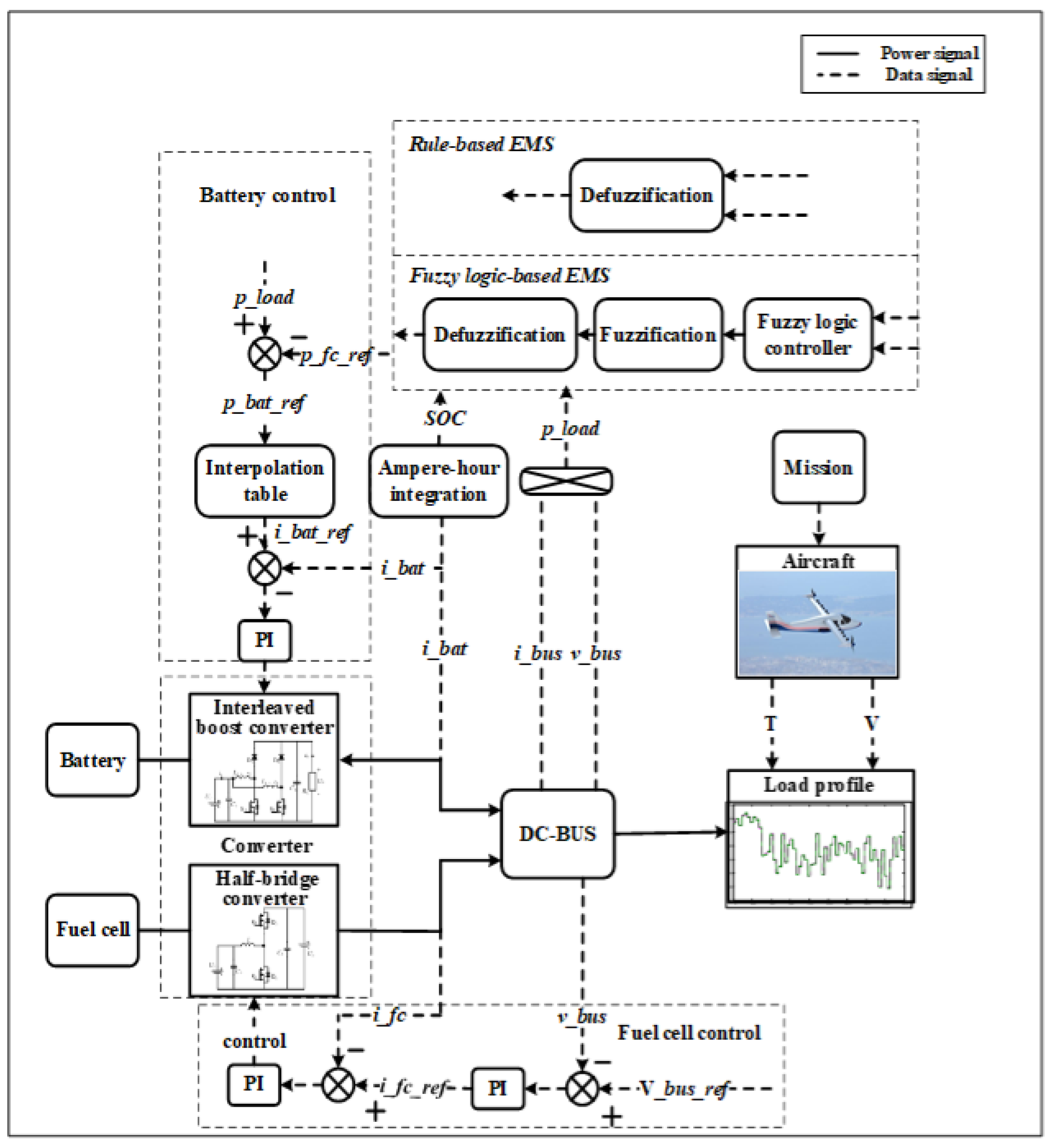
The considered architecture of the HEPS of the UAV is shown in Figure 2. The electric motor is used as the propulsion system of the UAV, which is powered by hybrid electric power sources, including a Proton-Exchange-Membrane Fuel Cell System (PEMFCS) and a lithium-ion battery pack system.
The parallel HEPS layout with two distributed DC/DC converters is able to control the DC bus voltage and the output power simultaneously [23,24]. In general, in the hybrid power system battery capacity is relatively small, which is mainly responsible for peak shaving and valley filling of energy during variation of load power. This architecture allows three operation modes: (i) both the fuel cell and lithium battery support the load power together; (ii) the fuel cell provides power to the load and surplus energy will be charged by battery; (iii) only the fuel cell is at the working state and the battery is disconnected. How to distribute the energy between the fuel cell and battery optimally is the main problem of EMS.
2.1. Modeling the Flight Dynamics of UAV
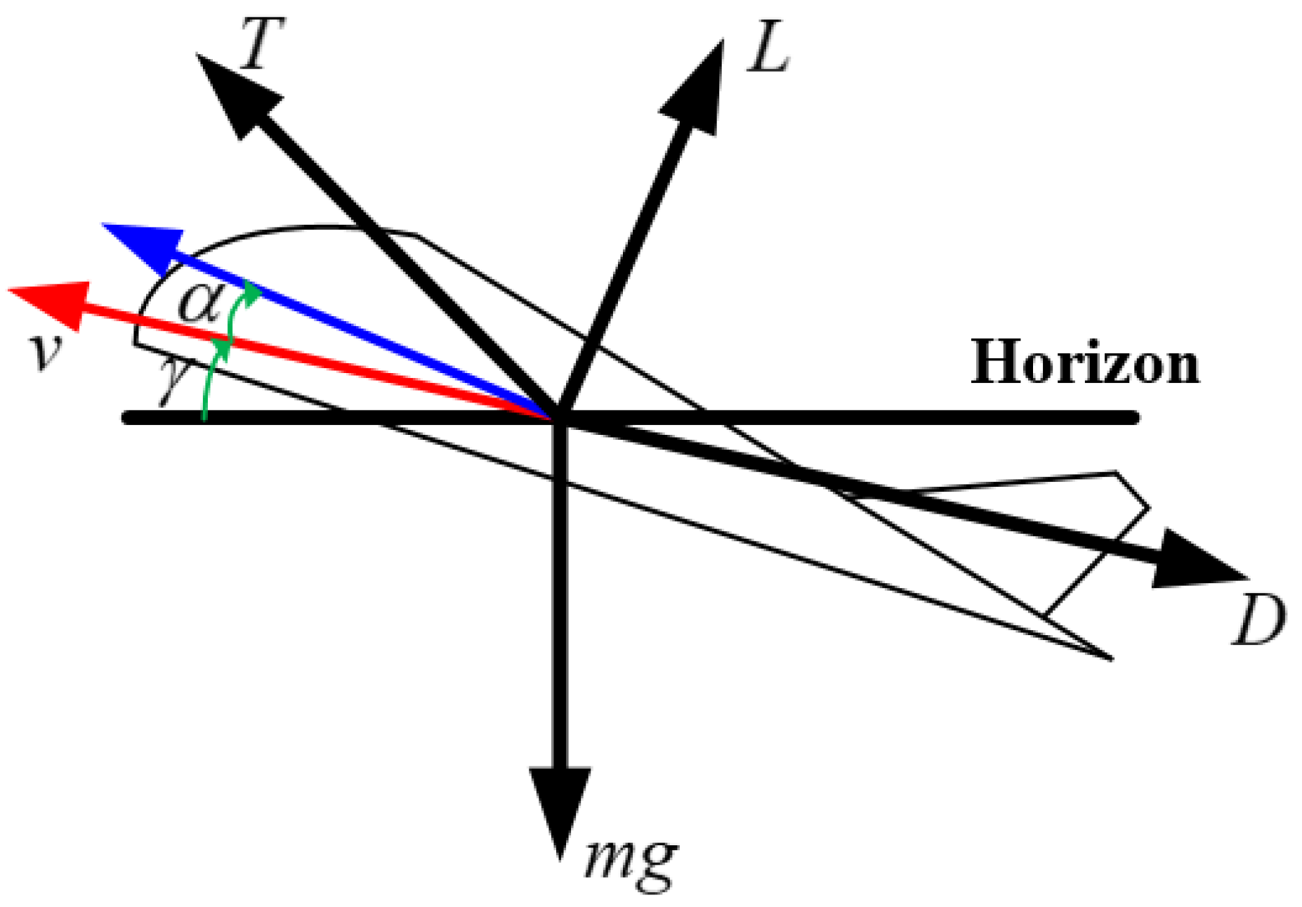
Take centralized electric propulsion UAV as research object, the UAV is regarded as a mass plane. The aerodynamic analysis of the UAV during climbing flight is shown in Figure 3, where represents the lift force generated by the different components of the aircraft in a wind axis reference frame, represents the drag force received by the aircraft, represents the thrust provided by the propeller to the aircraft, is the angle of attack, represents the track angle.
According to the testing results of wind tunnels and other methods from CFD calculation tools, the amount of lift and drag can be expressed by the Formulas (1) and (2).
where the is air density at the current flight altitude, is the relative velocity (flight velocity), is the wing planform area, and represent the lift coefficient and drag coefficient, respectively.
During the flight of the aircraft, the following equation can be obtained by analyzing the force in the horizontal and vertical directions of the aircraft’s speed.
Based on the above analysis, the propulsion load power of the UAV at the climb stage can be expressed as follows:
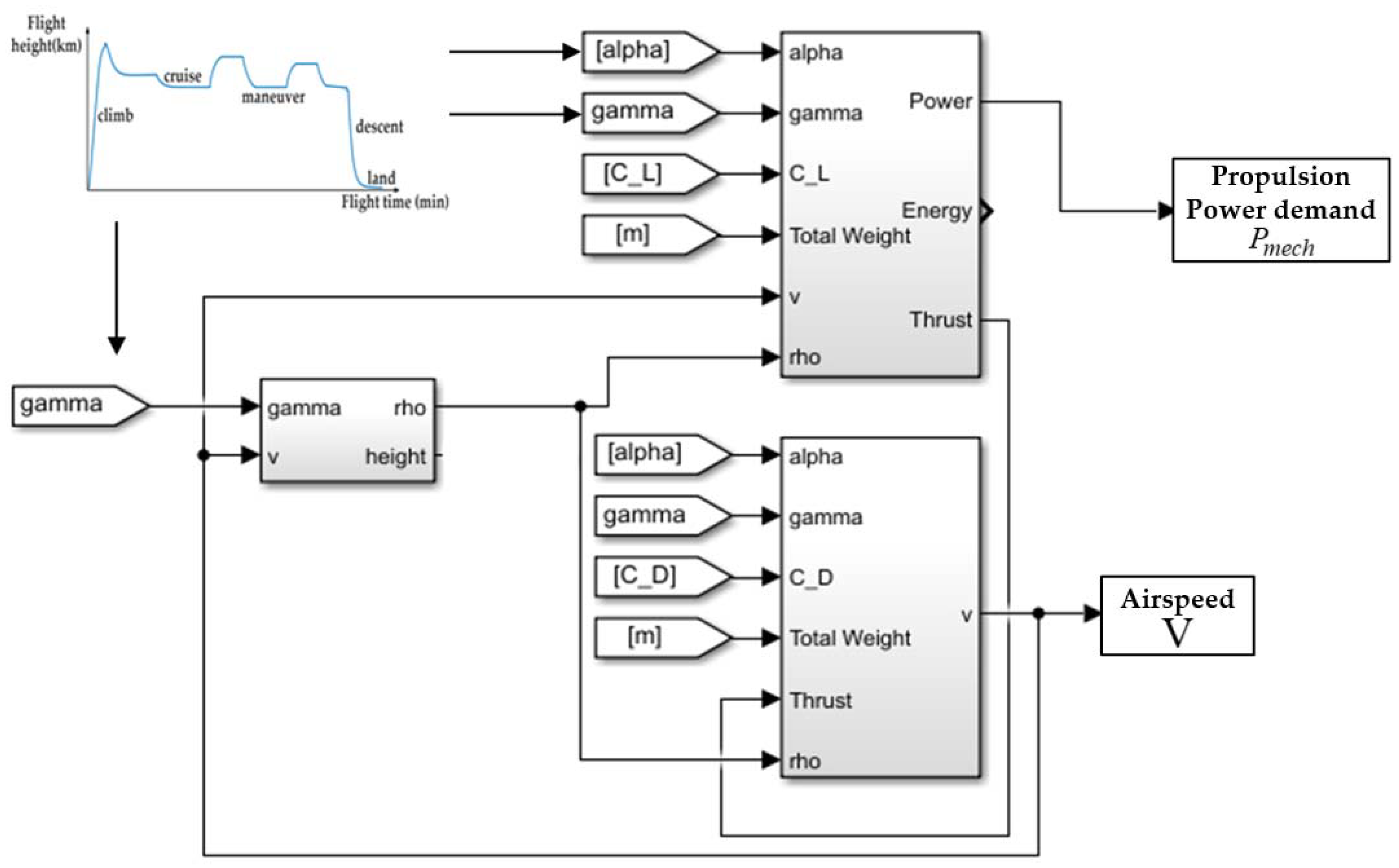
Generally speaking, the complete flight process of an aircraft includes the following six typical stages: ground taxing–take off–climb–cruise–descend–landing. The power variation of the UAV has been obtained from the flight dynamic force analysis results of the aircraft shown in Figure 3. It is shown that the thrust generated by the propeller is closely related to the aircraft’s track angle and angle of attack, and the aircraft has different track angles and angles of attack in different flight attitudes, so by defining the aircraft’s track angle and angle of attack in each flight phase, the specific thrust requirements can be determined, as well as data such as the aircraft’s flight speed and power. Using Equations (3) and (4), the thrust of the propeller and the acceleration of the aircraft can be calculated, and then the propulsion power and the flight speed of the aircraft can be calculated with Equation (5). In the case in which a mission profile is given, the propulsion power obtained in the research can be shown in Figure 4. The computation process and designing tools are presented in this part to obtain the real-time variation of flight power of UAVs. From Figure 4, the computation process is the concurrent iterative process, and the air speed of UAV and propulsion power demand can be fetched.
2.2. The Fuel-Cell Model
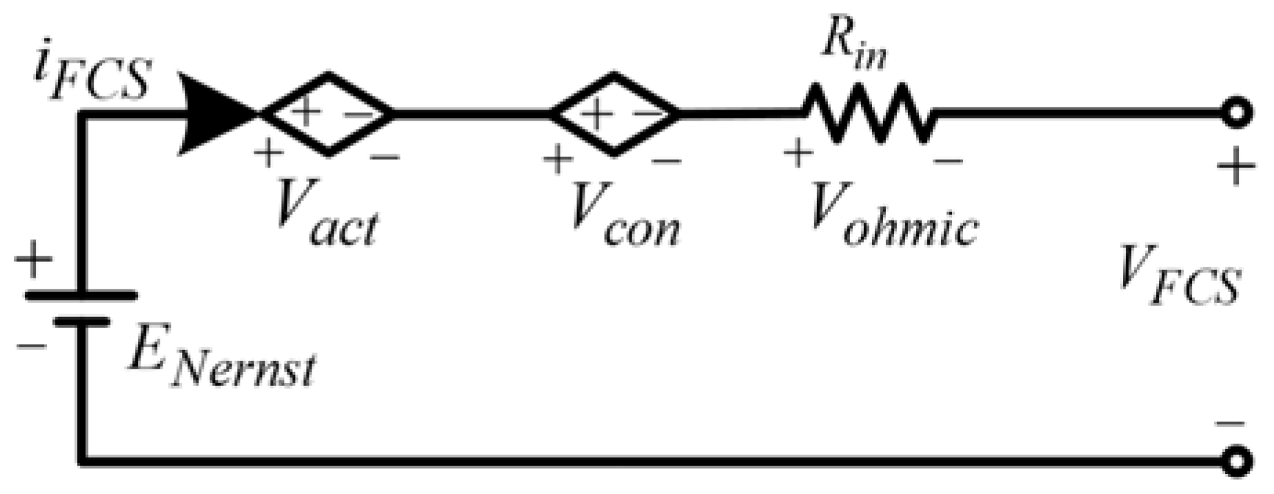
The characteristics of the Proton Exchange Membrane Fuel Cell (PEMFC) can be seen in Section 2.3. Figure 5 shows the model structure of PEMFC. The specific parameter calculations are as follows:
where is the output voltage of PEMFC, is the number of cells, is the reversible cell potential (), is the activation loss (), is the concentration loss (), is the ohmic loss (). The is defined as follows:
where is the fuel cell temperature (), is the hydrogen supply pressure (), is the oxygen supply pressure ().
The activation loss is caused by the slowness of the reactions happening on the electrode’s surface. It can be defined as the following formula:
The are the empirical parameters under actual working conditions, is the oxygen concentration (), is the fuel cell current. The ohmic loss can be regarded as the internal resistance loss of the battery, which can be defined by:
where is the internal resistor (), are empirical parameters.
where is an empirical coefficient, is the current density during fuel cell operation (), is the maximum current density of fuel cell ().
2.3. The Battery Model
The battery model is based on the simplified first-order RC model in Figure 6.
The State of Charge (SOC) and output voltage are calculated as:
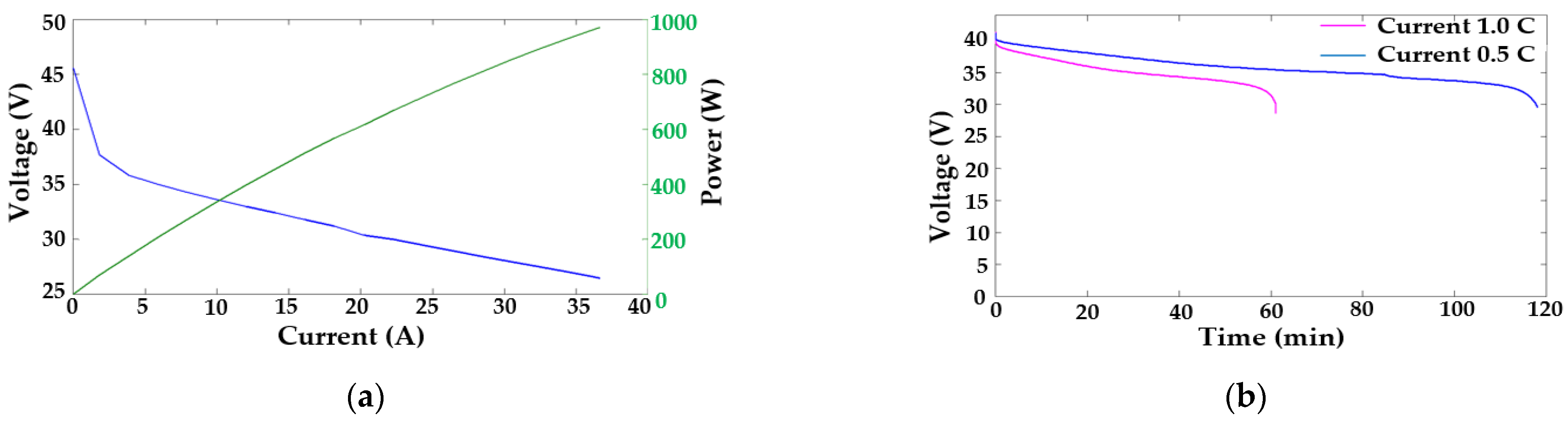
where is the voltage across capacitors, is the voltage drop across the internal resistor inside the battery. The discharge curve of battery pack is shown in Figure 7b.
2.4. The Power Flow in the Power-Train of UAV
As shown in Figure 2, in order to meet the power balance requirements, the output electric power of HEPS must be equal to the load power required by the UAV if the power loss can be negligible. The relationship of the power balance in UAV is shown as follows:
where the is the total output power in the UAV, which includes the fuel-cell output power and battery power . The is the power of electronic equipment onboard UAV, and is electricity propulsion power. After three stage transformations, real propulsion power demand of UAV is energy from the HEPS through the speed controller (inverter or DC/AC converter), electric motor and mechanical propeller. The , , are motor drivers, motor and propeller power flow conversion efficiency.
3. Energy Management Strategies for Hybrid Power System of UAV
The problem for the energy optimization is the minimization of hydrogen gas consumption during the flight stage of UAV under different operational modes and power load demands. The energy management controller is used to regulate the power flow between the fuel cells and energy storage system in real-time during the flight time of the UAV. The efficient implementation of the energy management controller is to (i) track the DC bus voltage reference trajectory, (ii) reduce power stress on the fuel cell due to changes in the electric propulsion load, and (iii) keep the battery SOC within allowable limits. The controller in HEPS can be divided into two levels: secondary level and primary level. The decision stage on the secondary level is realized based on the energy management strategy to calculate the output power distribution ratio of the hybrid power supply. The controller on the primary level can use a PID control loop to adjust the output power of the fuel cell and battery according to the reference power from the secondary level. According to the overall block diagram of energy management and power controller for the power system shown in Figure 8, several energy management strategies are proposed in this section. It is important to emphasize that the DC bus voltage should be kept at a constant value or in a range with transient voltage dynamics for UAVs. Further explanation of EMS is presented as follows:
Rule-based control (also known as state-machine control) is a classical online strategy for HEPS of UAV, which is described as a number of operation states based on deterministic thresholds. The proposed RB control can regulate the power split between fuel cells and batteries according to the real-time load power and SOC of batteries with lower computational burden. The ampere-hour integration and open circuit method are adopted for estimating SOC in this paper, the corresponding formula and the discrete formula can be expressed as [26]:
where is the initial SOC, which is available from the measured open voltage-SOC curve, i(t) is the battery current, the value will be positive when discharging and be negative when charging, is the rated capacity of the battery pack, is the solver time step.
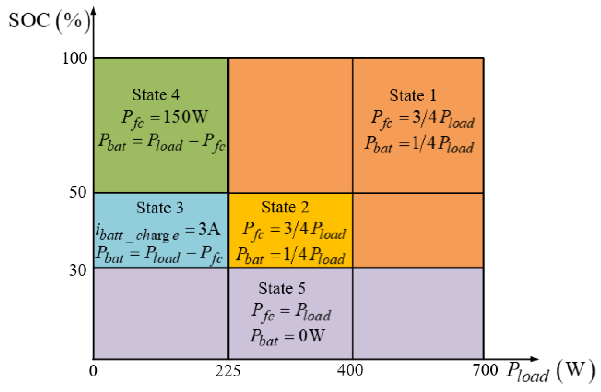
The logic scheme of the proposed RB strategy with five states is shown in Figure 9. is the total power demand of UAV, is power supplied by the fuel cell, is the power supplied by the battery, is the charging current of the battery.
Based on the proposed EMS, batteries could share enough power with different ratios when the demand is at a high level and absorb excess energy during lower load power. As an emergency power source of UAV, sufficient stored energy is also maintained in batteries for some fault scenarios. Notably, an over-complicated division for operation states is hardly inevitable and it will only cause needless computational burden and even destabilization of the controller. In addition, the power limitation for PEMFC and batteries is requisite for safe operation, and it will ensure both power sources operate in a relatively stable working state. Referring to the parameters in the UAV design requirements, all constraints for HEPS of UAV can be summarized as:
3.1. Fuzzy Logic-Based EMS
Essentially, fuzzy logic control can be interpreted as a kind of RB control but in which the thresholds are fuzzed by a series of “IF-THEN” rules [28]. It is generally recognized that the robustness and optimization performance of FL control is greater than RB control. Unlike the classical rule-based control, the Fuzzy Logic Control (FLC) deals with reasoning using an approximate way rather than the precise way. As a result, the FLC is tolerant to imprecise measurements and variations of input variables, thereby being robust against system uncertainties.
3.1.1. Fuzzification Module
The typical Mamdani-type reasoning method is selected, and the membership function is designed with triangle and trapezoidal functions. The fuzzy subset of load power of UAV is divided into four blocks, namely, zero (ZE), small (PS), median (PM) and large (PB); the fuzzy subset of SOC is divided into three blocks, namely, low (L), medium (M) and high (H), the fuzzy subset of fuel cell reference power is divided into off (OFF), off–average hold (HOA), average (AVE), average–medium hold (HAM), medium (MED), medium–maximum hold (HMM), maximum (MAX). The designed membership functions are depicted in Section 3.2.4.
3.1.2. Inference Module
As far as the choice of inference mechanism is concerned, one of the following three methods is usually chosen, such as MAX-MIN, MAX-PROD, and SUM-PROD. This article used MAX-MIN. The corresponding fuzzy rules are listed in Table 1. According to Table 1, when the power demand of the UAV is in zero blocks and the power is very small, the SOC of the battery is low, and then the output power from the fuel-cell is from the off to average level hold section to prevent the battery from over-discharge. When the power demand of the UAV is in zero blocks and power is very small, the SOC of the battery is medium, and the output power from the fuel-cell is in the off section, which can reduce the hydrogen consumption greatly. When the power demand of the UAV is in the PB blocks and the power demand is very large, according to the SOC level of the battery, the output power from the fuel-cell can be adjustable to reduce the hydrogen consumption and maintain some level of SOC for the battery.
3.1.3. Defuzzification Module
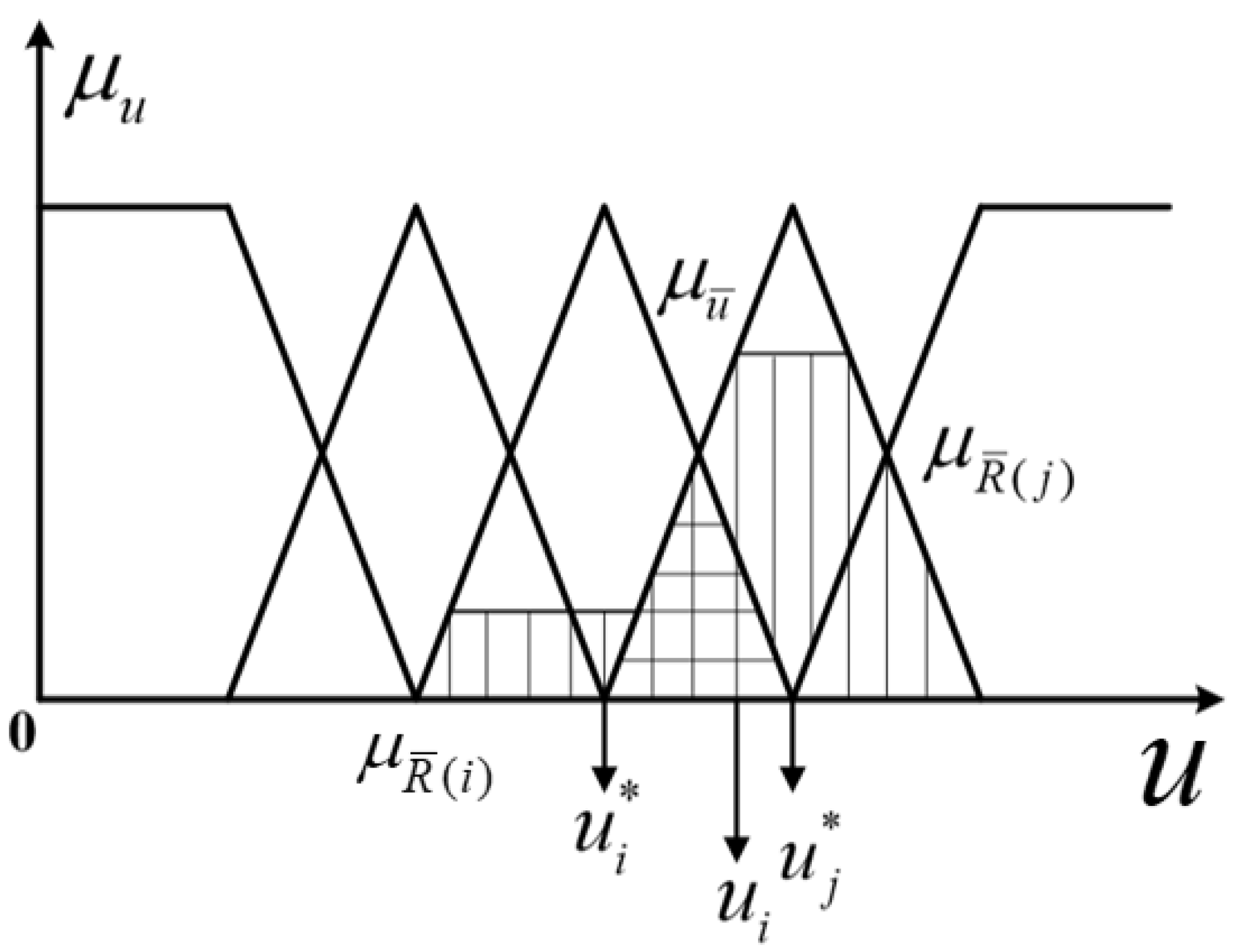
A lot of defuzzification methods are used in the case of fuzzy controllers. Two most often used defuzzification methods for those fuzzy controllers are the mean of maxima method and the center of gravity (CoG) method. In this study, the center of gravity method is used for defuzzification for the FL. The CoG method determines the crisp value of output, taking into consideration, in a weighted manner, all influences obtained from the rules fired by the particular state of the inputs at a certain moment. In the discrete case, the abscissa of CoG can be calculated by the following formula:
In this equation, is the number of the active rules, is the weighting factor from the -th rule, is the crisp value defined in the output universe and corresponds to the center of the core set of the output fuzzy set. The operating principle of the CoG method is exemplified in Figure 10.
3.1.4. Fuzzy Controller
In Section 3.2.4, ‘0–1’ represents the ratio of the HEPS system output power to the maximum output power (700 W), the ratio of battery SOC, and the ratio of fuel cell output power to the maximum output power (700 W). Section 3.2.4 draws the output surface diagram of fuel cells under the area center method for defuzzification.
3.2. Fuzzy Logic-Based EMS Optimized by PSO
As mentioned in the previous section, the formulation of deterministic or fuzzy rules are invariably restricted by cognition, experience and acknowledge of designers, and it becomes an inevitable constrain for the further improved optimization effect [40]. The particle swarm optimization algorithm is a kind of population-based parallel random searching algorithm with fast speed and a wide hunting range. The optimal solution will be tracked through collaboration and information sharing among individuals in the population such as flocks of birds or schools of fish. These features provide the possibility to adjust the thresholds of membership functions in fuzzy logic control in optimization form [41].
3.2.1. Build Optimization Goals
An optimal objective function must be set at the beginning, which is the precondition and target for tracking the particle swarm algorithm. Taking the overall hydrogen consumption economy of HEPS for the UAV into account, the equivalent hydrogen consumption with a penalty function has been proposed, and the instantaneous expression representation is as follows:
where , are the hydrogen consumption of fuel cells and equivalent consumption of batteries, is the total hydrogen consumption on the hybrid power system, respectively, is the number of the cells inside the stack, is the Faraday constant, is the molar mass of hydrogen, is the sampling time, is the adjusting coefficient.
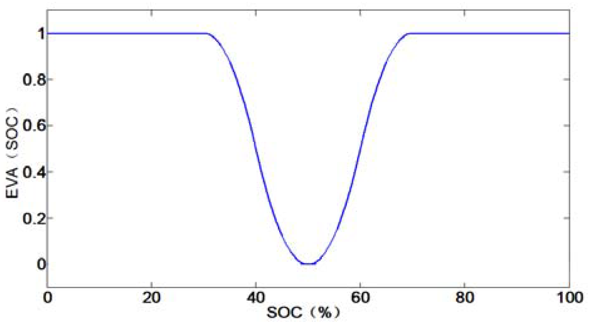
is the penalty function based on the fuzzy logic membership function, which can further adjust the weighting of equivalent consumption and maintain the SOC in a rational range. ZMF and SMF are the Z type membership function and sigmoid membership function. As shown in Figure 11, the penalty function is added to keep the battery SOC within the range of 30–70% as much as possible.
It is noteworthy that the equivalent consumption of batteries here is not a precise quantification but a weighing concept, and the power distribution between fuel cells and batteries can be managed by regulating the adjusting coefficient.
3.2.2. Particle Swarm Algorithm
A swarm particle algorithm can be represented by the two q-dimensional vectors and standing for the particle position and the particle velocity. The optimal location for the particle itself is , and the entire swarm optimal location is . The particle position and velocity update equations that govern the PSO algorithm can be expressed as follows:
where is the number of iterations, is the weighting factors of the stochastic acceleration terms that pull each particle toward their position. Low values allow particles to roam far from the target regions before being tugged back. On the other hand, if a high value of is used, particles may pass the target regions. represents a random function that can generate a random value between 0 and 1, is the inertial coefficient, which shows the effect of the previous velocity on the current velocity.
3.2.3. Particle Swarm Optimization Settings and Process
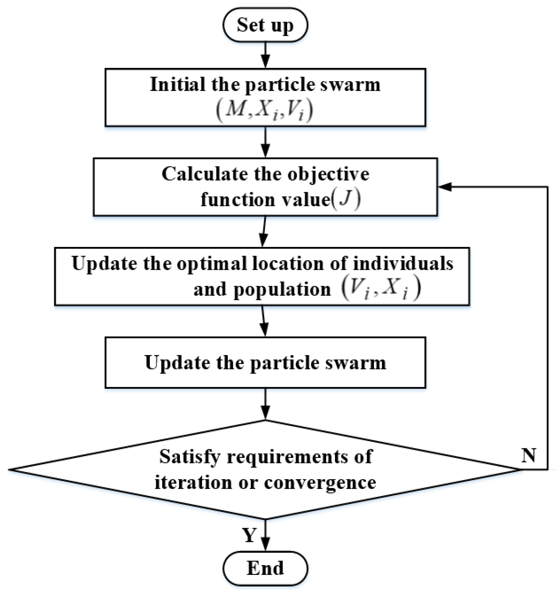
This paper uses the weighted global particle swarm optimization algorithm to optimize the fuzzy logic membership function designed in the previous section. The detailed flow chart of PSO is shown in Figure 12. The main parameters are set as follows:
- (1)
- Objective function: equivalent hydrogen consumption, see Equation (17);
- (2)
- Population size M: usually the size of the population size will affect both convergence and tracking speed. Set as 20 in this article;
- (3)
- Particle dimension: The dimension of the child corresponds to the number of boundary thresholds in the membership function, which is 17;
- (4)
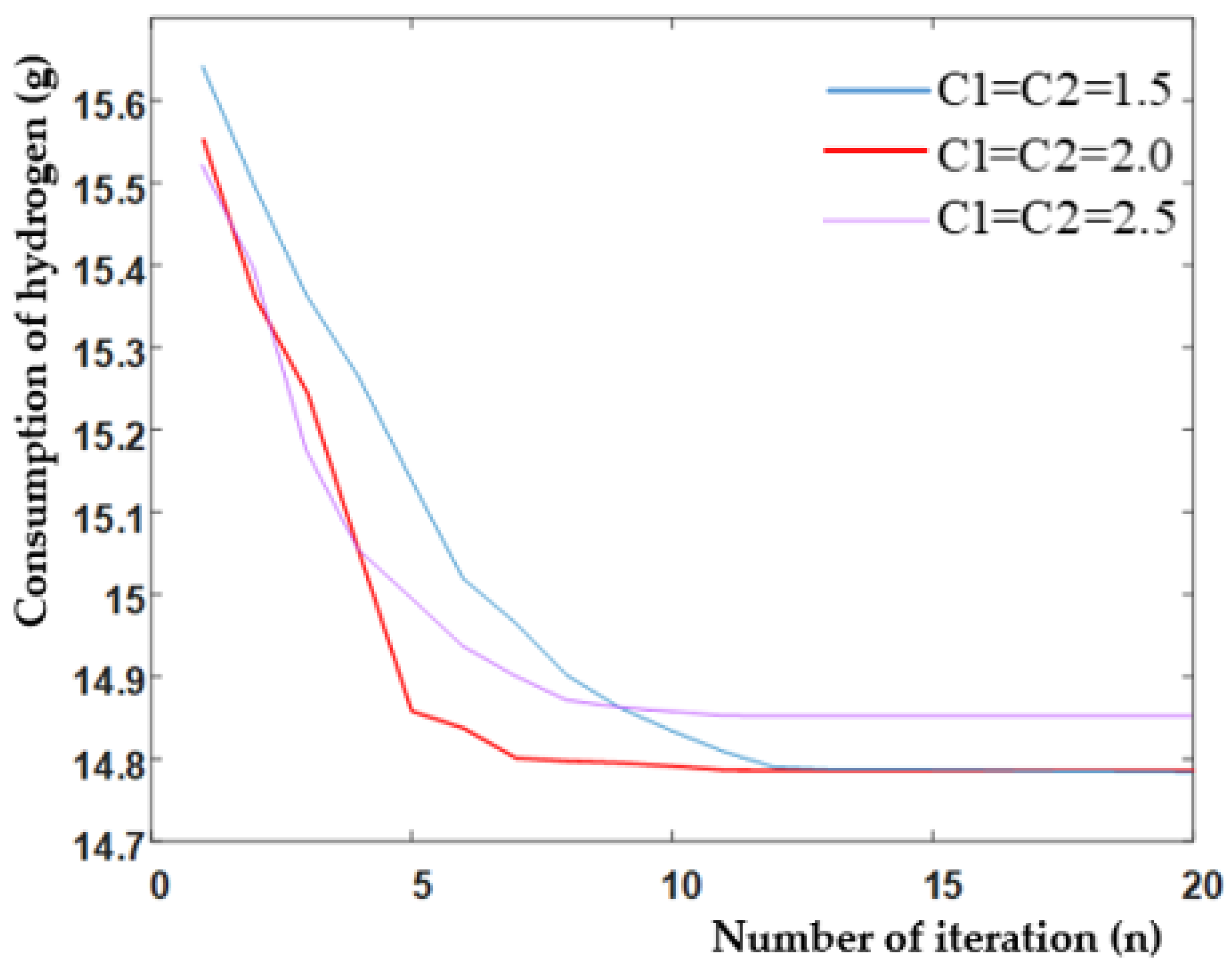
- Position speed update formula: inertia weight = 0.4, the weighting factors have a great influence on the optimization process, as shown in Figure 13, finally c1 = c2 = 2;
- (5)
- Maximum number of iterations and convergence limitation: In this paper, the maximum number of iterations k = 30, and if the algorithm results can converge early, the iteration will be terminated early. Determine whether the convergence condition is satisfied by setting the incremental value threshold of the optimal fitness, the incremental value threshold e = 1e − 3;
- (6)
- Speed limit: A flight speed that is too fast will cause the result to oscillate near the optimal solution, which will affect the accuracy of the algorithm; a flight speed that is too slow will affect the convergence speed. There is a trade-off between the two when setting the flight speed.
- (7)
- Position restriction: In order to ensure the correctness and validity of the membership function, it is necessary to limit the tracing range of each boundary threshold.
The algorithm will be circulatory until maximum iterative times are achieved or the result converges to an approximately constant value.
The convergence curve of the PSO algorithm under different weighting factors is shown in Figure 13, and it is shown that the convergence of the algorithm can be achieved after 12 steps by choosing proper weighting factors. From Figure 13, the convergence curve with red color is the most quickly descending rate compared to other factors. Therefore, the weighting factor was chosen as 2.0 to accelerate the computation speed.
3.2.4. Particle Swarm Optimization Results Analysis
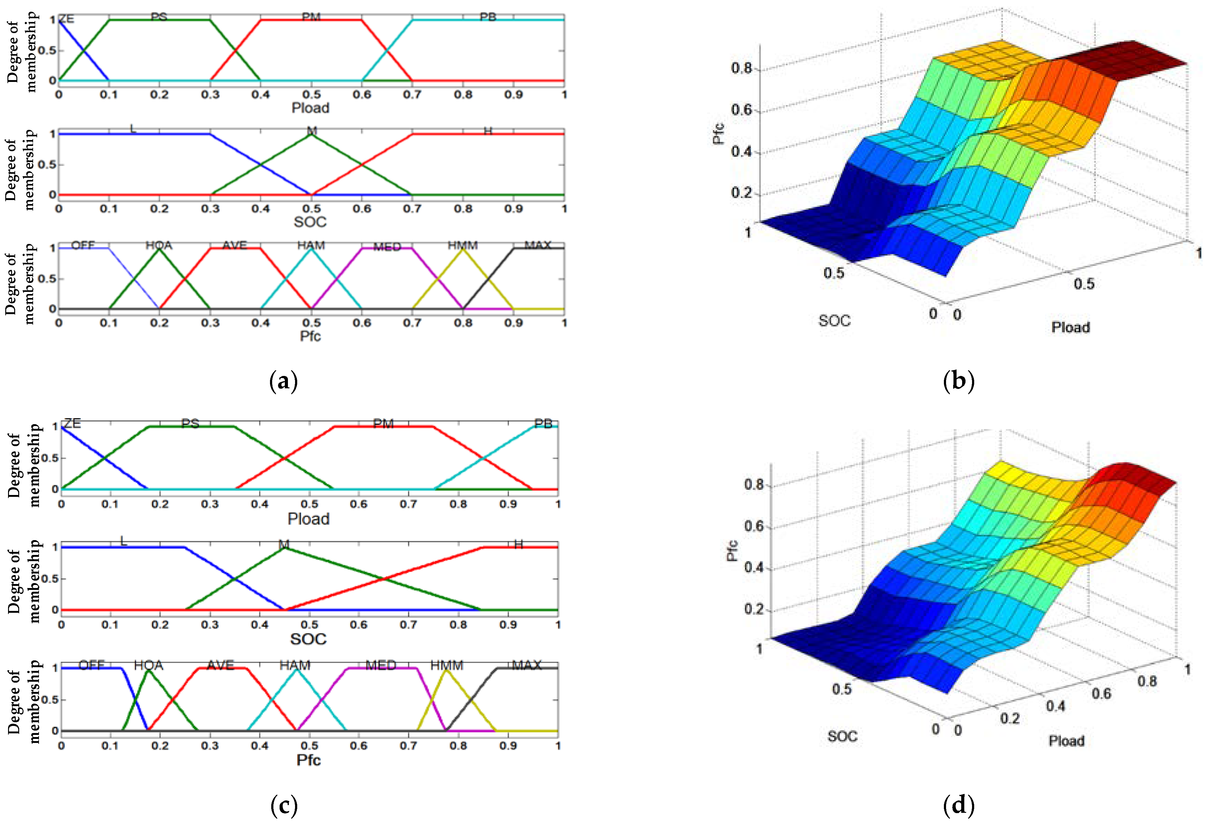
The improved membership functions of the PSO-FL controller and corresponding output surface diagram can be seen in Figure 14c,d. According to the PSO algorithm to optimize the boundary thresholds of (17) membership functions, it can be seen that the threshold of membership function of Figure 14c was chosen more uniform than that shown in Figure 14a, and the output surface of fuel cells in Figure 14d under PSO is smoother than that shown in Figure 14b, and it means that the operating characteristics of fuel cells would be more stable over the full power range of HEPS for UAV. The controller structure of HEPS is shown in Figure 8. The PSO algorithm is accomplished offline by using the predictable mission profile of UAV to obtain the optimal threshold value for the fuzzy logic controller. The fuzzy logic controller can be used to complete the supervisor controller function online. This method can greatly reduce the computation burdens for EMS of UAVs. Although the prior information of the future power demand of UAV may vary due to some disturbance factors such as wind shear, attitude control and payload changes, the average power profile is smoother than that of EV or HEV. The fuzzy logic EMS is more suitable for UAV.
4. Rapid Controller Prototype Experimental Testing Bench
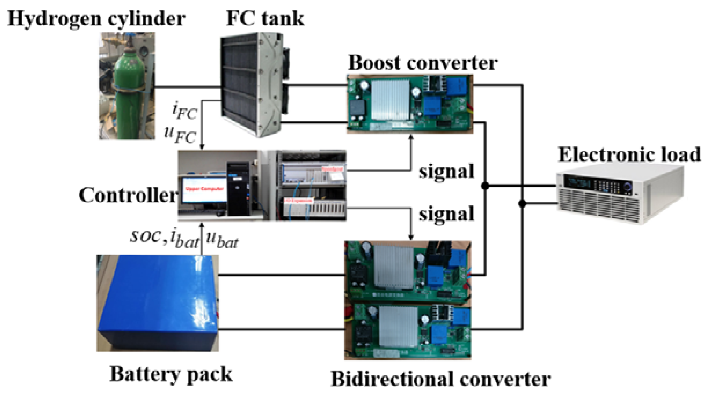
The focus of this research primarily concentrates on verifying the performance of the energy management strategy presented in this paper rather than the architecture and load characteristics of HEPS for UAV. Use a UAV flight simulation model in the MATLAB/Simulink environment with a Powertrain Block set. For the sake of convenience, all-electric loads, including the AC and DC load in the HEPS, are uniformly replaced by an equivalent DC load emulator. Based on the above contents, the schematic diagram of the ground experimental testing platform based on RCP is shown in Figure 15. The main system experimental parameters are summarized in Table 2. The PEMFC system is the 1.2 kW Horizon fuel-cell stack with a controller. The lithium-ion battery is based on 18,650 battery cells (single capacity 2.5 Ah, rated voltage 3.7 V), using series-parallel, output voltage 42 V, rated energy 10 Ah. The RCP system is the Speed-goat HIL platform, in which the EMS and power converter’s controller are integrated. In the energy management context, the speed-goat test-bench is implemented to offer a rapid controller prototype (RCP) simulation by interfacing the PSO-FL algorithm section into the hybrid power system with signal conditional circuits. The UAV’s flight power variation is emulated by DC electronic load emulator, which can be programmed in the upper computer. Although the simulation environment cannot entirely reflect the situation of a UAV in real-world experiments, the unmanned air vehicle flight simulator in the upper computer provides a realistic flight environment for verifying the proposed energy management system design.
5. The Analysis of Simulation and Experimental Results
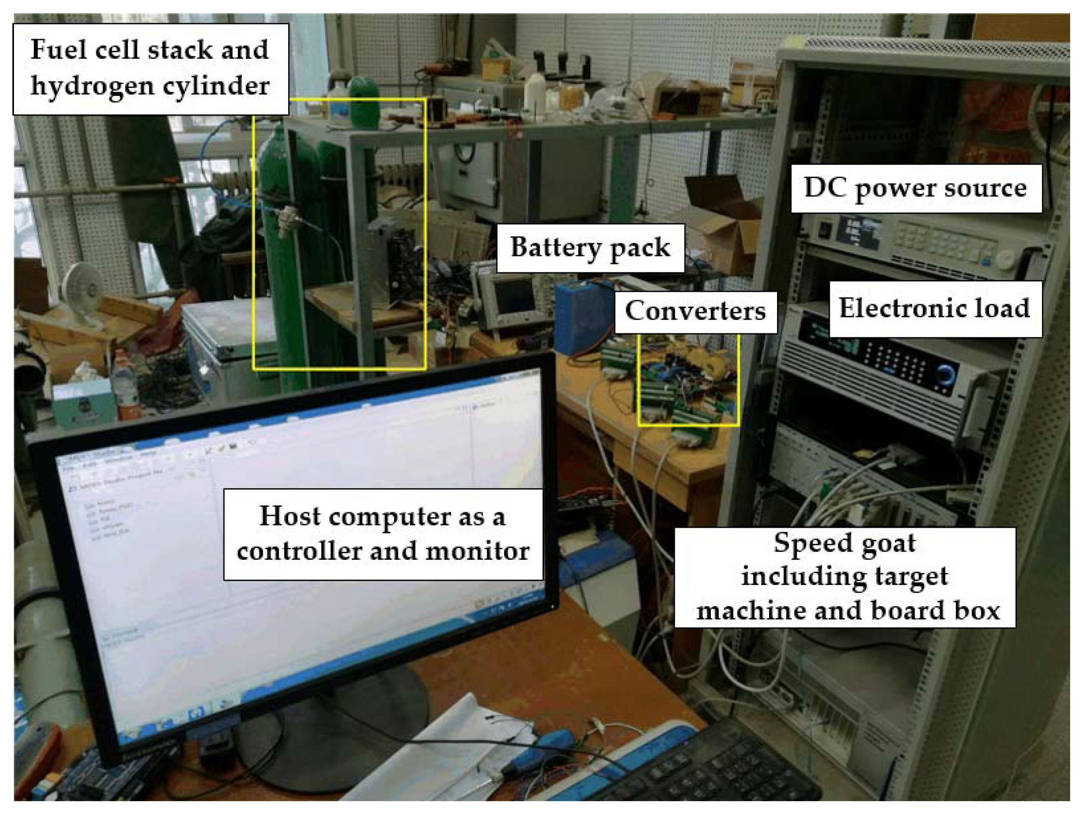
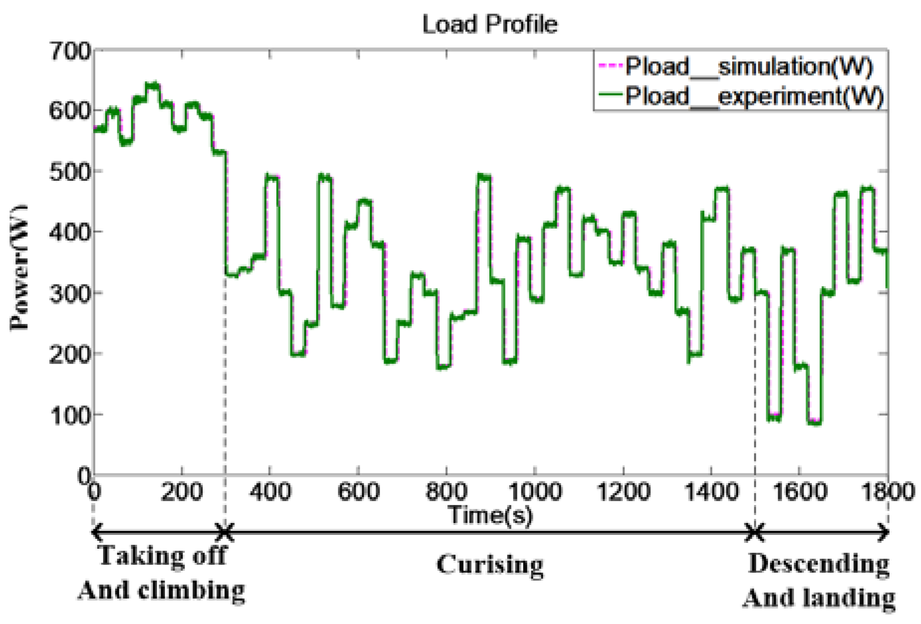
The performance comparison of three EMS strategies mentioned in Section 3 has been validated by the Simulink models and ground RCP testing platform (shown in Figure 16). The EMS controller, including sampling and driving control circuits, will be implemented online on the RCP platform. For comparison purposes, the initial SOC of the lithium-ion battery is set to 60% for each test scenario. All the experimental waveforms will be recorded and stored by the data recorder GENESIS 7T for monitoring and further analysis. The power profile applied here is designed with reference to the practical flight profile of the UAV. Table 3 gives the specific power of every flight stage, and the given power profile under simulation and constant power mode of the DC electronic load are shown in Figure 17. The continuous high-power variation is needed as a thrust force while taking off and climbing for UAV. The segment of cruising has the longest duration and the overall power demand is relatively stable and smooth. Significant power fluctuation occurs in descending and landing for maintaining flight attitude. Considering the safety and reliability of flight for UAV, the power volume of the power source, including the fuel-cell and battery, is larger than the peak power demand of electric propulsion and onboard equipment. If there is any fault in fuel-cell power system, the battery can supply electric power energy for the emergency flight.
5.1. The Power Distribution, SOC and DC Bus Voltage
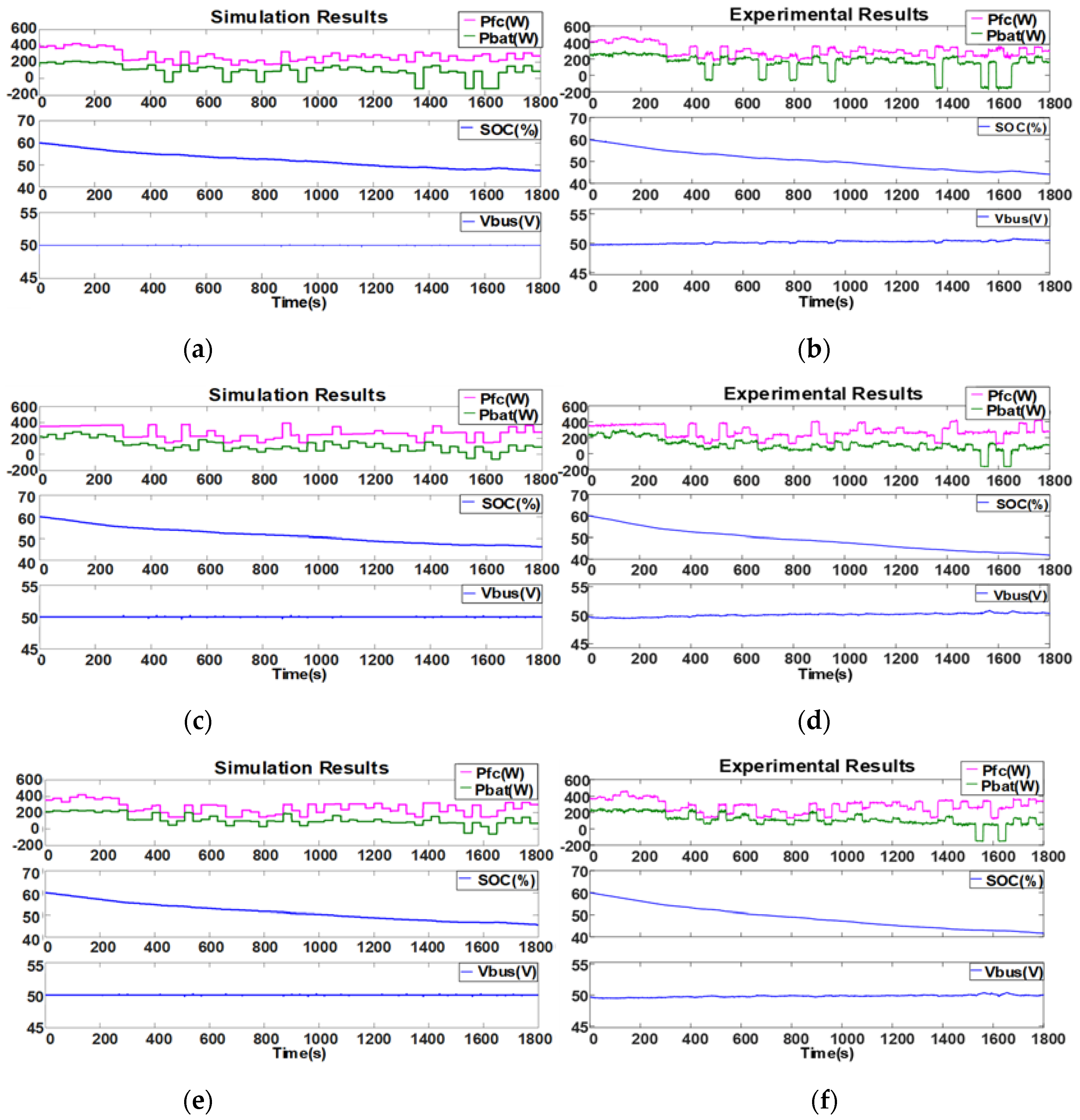
The power split response curves between fuel cells and batteries based on RB, FL and PSO-FL are shown in Figure 18, and the SOC and DC bus voltage waveforms are also recorded. is the power provided by the fuel cell, and is the battery unit power. It is concluded that the experimental results are compatible with the digital simulation results from Figure 18. A great response to the power profile has been achieved in the HEPS on the premise of keeping the voltage of the DC bus at 50 V, and the feasibility of designed strategies could be proved. Under the RB control, the PEMFC is charged to the battery pack many times during lower power requirements, which means the energy stored in the battery pack is not utilized adequately. Moreover, each change of load power almost always results in a corresponding change of power split. Meanwhile, the power response under the two other fuzzy logic controls is significantly smoother, and the battery energy has been efficiently used. A comprehensive summary of the experimental data can be found in Table 4.
For fuel cells, the two main aging factors or high stress are the frequency of output power changes or rapid output power changes of the FC and operation at high output power conditions. For the battery, as the number of charging and discharging cycles of the batteries increases, the aging rate of the electric storage system (ESS) increases.
From Figure 18a, the rule-based EMS is simple to implement and consumes the minimum memory of the EMS’s control unit, but it depends heavily on the intuition and experience. The output power from the fuel cell and battery fluctuates frequently during the flight stage of the UAV, such as takeoff and cruising stage. According to Figure 18a based on RB, the fuel-cell power fluctuation is not smooth in the initial takeoff stage (0–300 s); meanwhile, the variation of the fuel-cell output power is very large in the cruising stage. At the end of the operation (in UAV descending stage, 1500–1800 s), the final SOC of the battery is above 50% because the battery is more involved in fuel-cell charging, which can cause large stress for the fuel cell. The DC bus voltage can be maintained at the 50 V level. The experimental DC-bus voltage’s ripple in Figure 18b is larger than the digital simulation result because of the disturbance from the switching noise from the DC-DC converter. The average number of charges and discharges for the battery is around eight from Figure 18a.
For nonlinear systems with multi-objective optimization, fuzzy logic EMS is easy to implement, but it is very difficult to tune the parameters of the membership function for optimal global control. In Figure 18c,d, the performance of FL regarding the distribution of power and battery SOC is demonstrated. From this figure, it is seen that in the very beginning (0–300 s), the output power of the fuel-cell is smoother than that of RB, and the SOC of the battery decreases more quickly. At the end of the operation (in the UAV descending stage), the final SOC of the battery is above 40%. During the cruising stage (300–1500 s), the battery is rarely charged by the fuel-cell until the descending stage. The average number of charges and discharges for the battery is approximately five or six according to Figure 18c, which can improve the lifetime of the battery compared with RB control methods. There are some minor differences between the simulation result in Figure 18c and the experimental result in Figure 18d. It can be observed that there are some atypical measurements in the experimental data caused by sensor measurement errors and slow dynamic response of the real stack.
The PSO-fuzzy logic EMS requires tuning fewer parameters of FL and is robust to the initial population size. It is based on the meta-heuristic optimization algorithm, which searches the near global optimal solution for the minimum value of fuel-cell hydrogen consumption. During the takeoff and cruising stage for UAV (0–1500 s), the power fluctuation is relatively smooth with PSO fuzzy logic EMS, which can improve the lifetime of the fuel-cell shown in Figure 18e,f. The declining rate of SOC based on PSO fuzzy logic is slower than the other two EMS strategies. The amount of charges and discharges for the battery is also less than that of RB and FL from Figure 18e,f. For the UAV application, the charge-sustainable and charge-depletion (CS-CD) of the battery must be traded off with the optimal operation region of the fuel-cell system. In this paper, the charge-sustainable of the battery is preferred compared with the charge-depletion mode for UAV application because the remaining energy from the battery can be used for the emergency situation of UAV and can extend the flight range of the UAV, and the battery cannot be over-discharged, which can degrade the life time and reliability of the battery. Therefore, the final SOC of the battery during the descending time must be maintained above 30%. However, the final SOC of the battery is not very high, but more than 50%, which can increase the penalty of the weight constraints of the UAV and is not economical for electrical propulsion aircraft. From the simulation and experimental result, the final SOC of the battery was above nearly 40%. It can be seen that the fuel cell and battery always work in the high-efficiency region, and the working points of the voltage bus for the driving motor are strictly distributed to satisfy the power demand of the UAV. It indicates that the PSO fuzzy logic-based energy management strategy learns to improve the HEPS working efficiency as much as possible.
5.2. Hydrogen Consumption and Overall Efficiency
The hydrogen consumption can be estimated by measuring the output current of the fuel cell in the project, as shown in the following Equation (20);
Similar to Equation (14), is the number of the cells, is the Faraday constant, is the molar mass of hydrogen. In addition, more attention was focused on the overall system efficiency rather than the efficiency of a single power converter or fuel cell battery, and the total efficiency could be defined as:
Notably, and are the output power of FC and battery (the input terminals for converters), respectively. is the load power of the UAV.
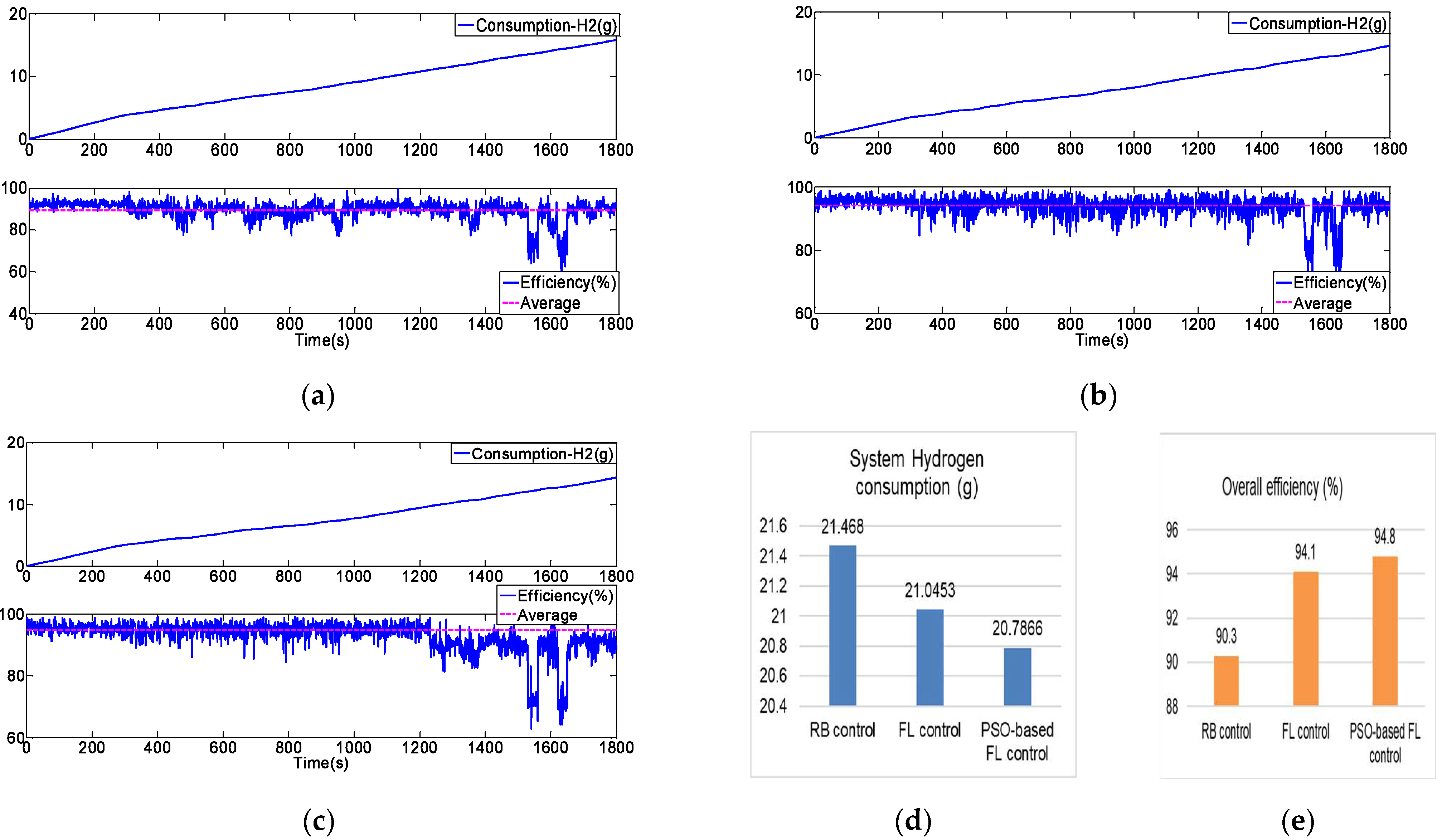
The real-time hydrogen consumption, overall real-time efficiency from experimental results and a more intuitive histogram for consumption and efficiency can be seen in Figure 19, respectively. In Figure 19a, the curve of real-time hydrogen gas consumption under RB control was presented, the final gas consumption is above 15 g at the end flight time of UAV, and the real-time efficiency curve changed greatly from the average efficiency of 90%. At the initial takeoff stage of the UAV, the efficiency of HEPS is nearly 93%, but during the cruising stage, the system efficiency changed greatly and then dropped quickly below 60%. In Figure 19b, the real-time consumption of hydrogen is less than the 15 g for UAV flight with the FL control, the efficiency curve of HEPS is nearly around 95%, and just at the descending stage, the total system efficiency drops greatly to 65% for a short time interval. In Figure 19c, the HEPS can always operate at an average efficiency of more than 95% with the PSO-FL control methods, and the real-time consumption of hydrogen at the final time is less than 15 g. At the stage of taking off, the instantaneous hydrogen consumption is the highest (the scope is the steepest), which coincides with the actual condition of flight for UAV. It is noted that the total system real-time efficiency during the descending time changed greatly from the reference efficiency of 95% with the PSO-FL algorithm, which is possibly caused by the improper random initial value of the PSO algorithm. For a whole flight profile, the minimum consumption can be achieved under the PSO-based FL algorithm, and this verifies the effectiveness of the improved EMS. In Figure 19d,e, the hydrogen consumption of the total flight time of the UAV and overall system average efficiency of HEPS are also presented. It is concluded that PSO-based FL control shows very superior performance compared with the other two EMS.
Normally, the UAV will carry a high-pressure gas cylinder, of which the hydrogen density is 3~4%. Taking a cylinder with the specifications of 9 L/35 MPa as an example, the actual mass of the carried hydrogen is about 280 g (standard conditions), which is calculated by the following formula:
where is the pressure of the gas cylinder, is the normal atmosphere, is the volume of hydrogen under standard operating conditions, and m and are the hydrogen molar mass and gas molar volume, respectively.
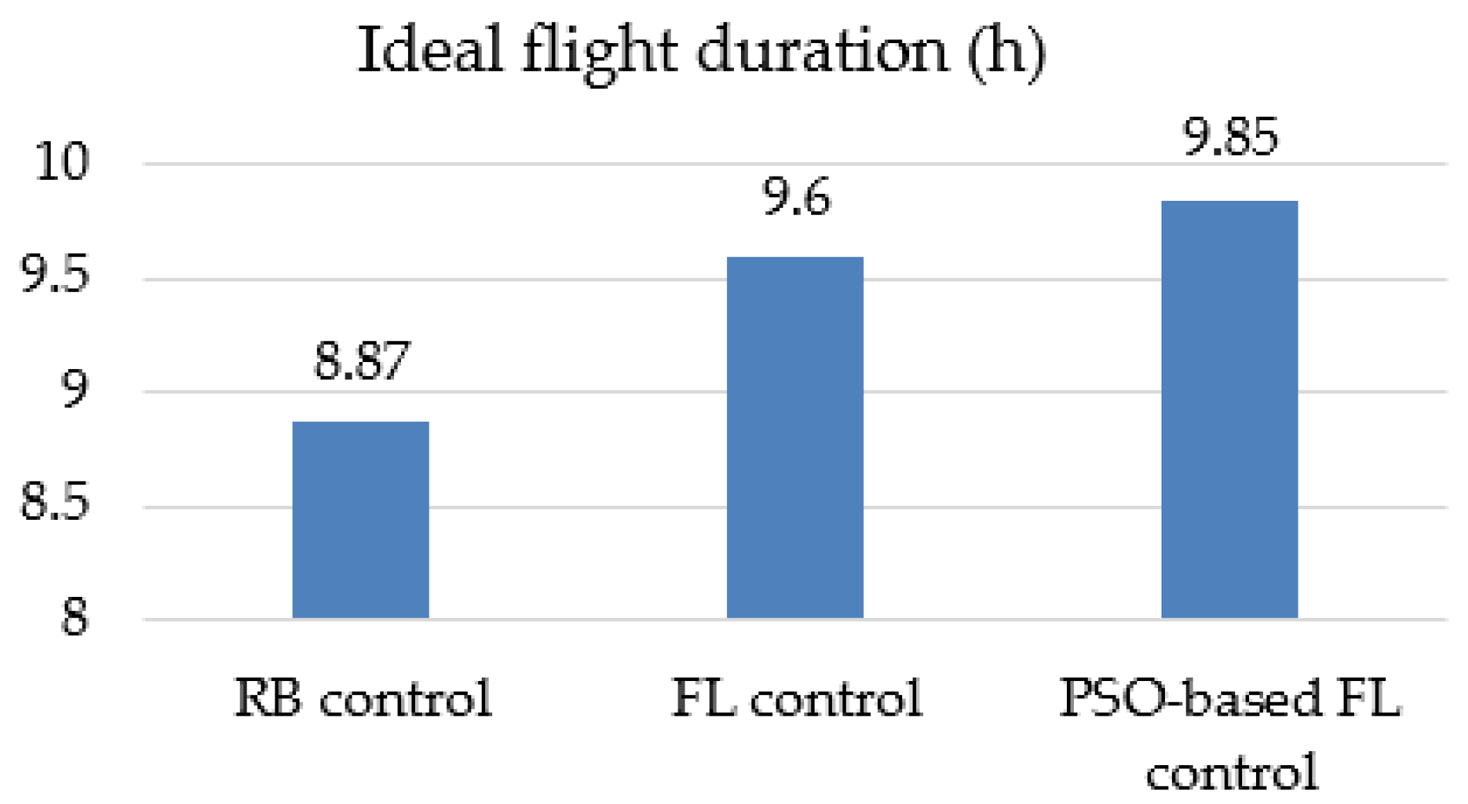
Scaling up the mission profile designed in the time domain under the ideal conditions with normal wind speed and climate, the UAV could fly for a duration time of 8.87, 9.6, 9.85 h under RB control, FL control, PSO-FL control, respectively; the compared results are shown in Figure 20. PSO-FL can achieve a longer flight range than that of RB and FL control, with an additional 15 min of flying time. According to a UAV flight speed of nearly 24 m/s, the flight range can be extended to 21.6 km.
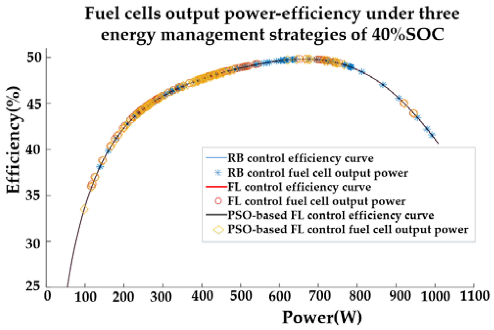
As the power train of a fuel-cell UAV is studied in this case study, the proposed energy management strategy learns to take full advantage of the benefits of the hybrid power-split structure by effectively releasing the fuel-cell from working in the low-efficiency region under the restrictions of flight conditions. Thus, the energy-saving rate of the UAV effectively increases with the higher hydrogen efficiency of the major energy consumption from the fuel-cell. As shown in Figure 21, the fuel cell efficiency curve under the three energy management strategies with an initial setting of 40% SOC for the lithium battery. Within the high-efficiency range of the fuel cell, PSO-FL is compared with the other two energy management strategies RB and FL. There are more points concentrated in the interval. This also verifies that fuel cells mostly work in the high-efficiency area under PSO-FL, and the efficiency of the entire hybrid power system is also higher.
5.3. Analysis on Stress and DC Bus Voltage Stability
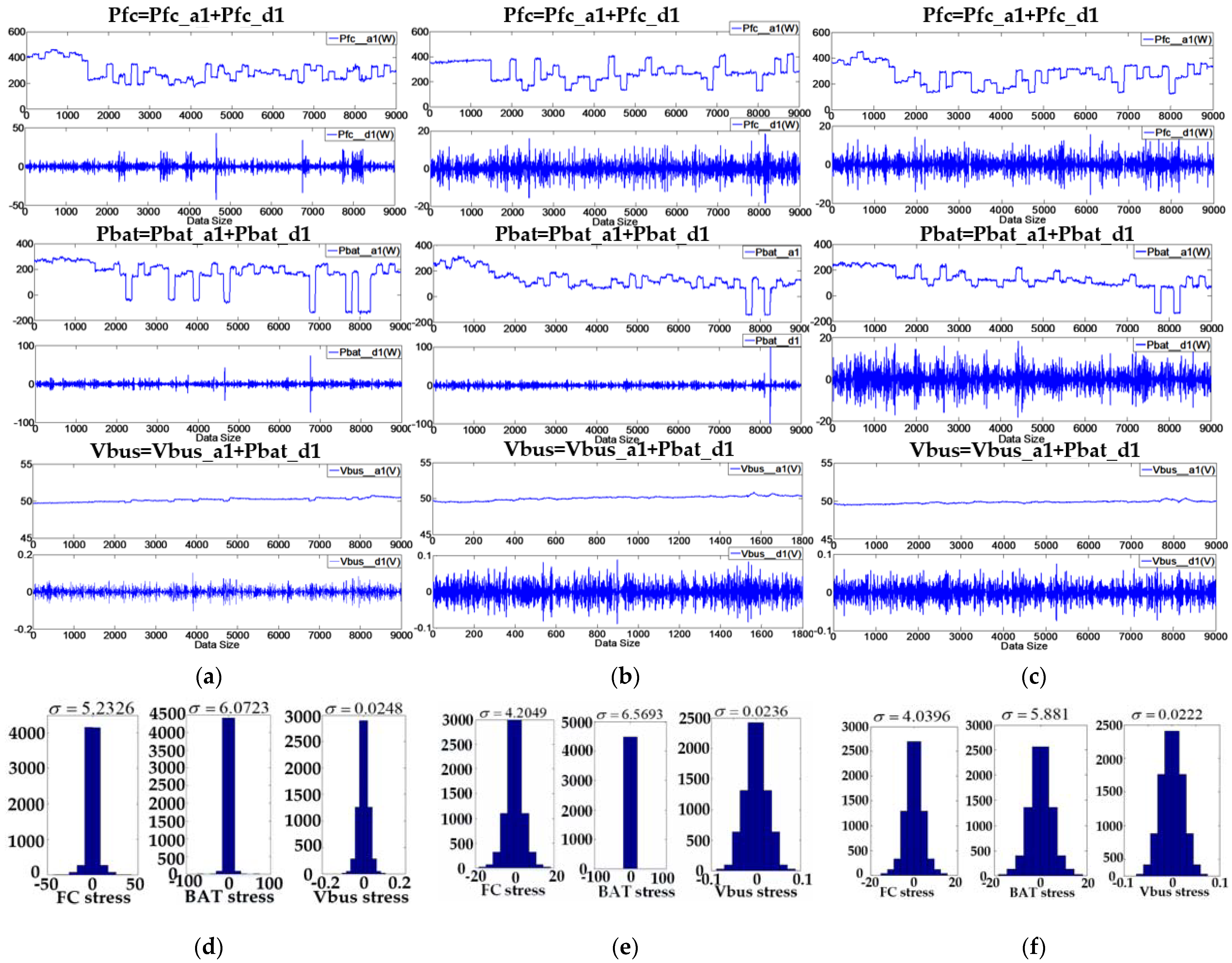
In order to further investigate the performance of different EMSs of UAV, the stress for each energy source and the stability of the DC bus voltage should be considered. It is believed that the power response with high frequency and fluctuations will increase the chemical stress inside the stack and aggravate the performance degradation of the fuel-cell of the UAV. The internal stress of energy sources can be evaluated by an approach based on the Haar wavelet transform and a fascinating feature of which the mean value of the decoupled high-frequency component is zero [32]. Thus, the standard deviations of this component can be used to estimate how often the energy sources are solicited for the UAV. This approach is also suitable for estimating the stability of the DC bus voltage of HEPS for a long time.
The detailed results of the decoupling analysis are shown in Figure 22, and the standard deviation can be seen in Table 4. In Figure 22a,d, the output power curve of the fuel-cell, output power of the battery and the DC bus voltage waveform can be transformed into one array of the time sequences data set by using the wavelet to decouple the high-frequency components of power from this data set. Probabilistic and statistical methods can be used to obtain stress distribution for different components such as fuel-cell, battery and DC bus. In Figure 22b,e,c,f, the same method is applied for the output power and voltage data set under the FL and PSO-FL methods.
As expected, the standard deviation of the high-frequency components of the power and DC bus voltage under two kinds of fuzzy logic strategies is less than rule-based control, which means the slower degradation of energy sources and more stable DC bus voltage. Another noticeable essential is that less hydrogen consumption in PSO-FL is based on the sacrifice of a part of stress characteristic since the stress performance is unconsidered in the objective function of the PSO algorithm. According to the above analysis, it is concluded that the PSO-FL EMS is fit for the fuel-cell UAV, whose mission profile and path are more predictable than that of EV or HEV. In addition, PSO-fuzzy logic EMS can reduce the computation burden and resource overhead greatly compared with complex EMS based on optimization such as con-vex-optimization, PMP and meta-heuristic optimization, as the PSO-optimization can be realized offline for the parameters of the membership for fuzzy logic. The real-time complementation is followed by the “if -then- else” logic process. It is very valuable to apply the PSO-fuzzy logic EMS in the UAV for a limited embedded controller platform.
6. Conclusions
This paper has presented a PSO-fuzzy logic-based EMS for a fuel-cell/battery hybrid power system of a UAV. The proposed strategy is more robust to load power changes compared with the well-known rule-based and fuzzy-logic strategy. In order to improve the hydrogen fuel economy, a particle swarm optimization algorithm has been applied to adjust the threshold parameters of membership functions of the FL controller. The optimization objective function performance will be evaluated in terms of hydrogen consumption, overall efficiency and stress analysis. On the basis of these results, the superiority of FL control and PSO has been proved and the near-optimized criterion is satisfactory. It is common that the PSO meta-heuristic and other intelligent algorithms such as deep learning neural network (NN) need to regulate the membership functions offline for the fuzzy-logic controller. When the load power profile is changed in real-time, the effect of EMS must be degraded because the overall flight profile can be unpredictable. In this paper, the dynamic flight model of UAV was developed to estimate the main load power demand accurately to overcome this shortcoming, which can be integrated with the EMS strategy. The simulation and HIL experimental results verify the proposed EMS strategies.
Some online EMS algorithms, such as MPC [35,36,37] and equivalent-consumption-minimum (ECM) [41,42], have been used to manage the HEPS, but these methods are only based on the limited time horizon length, and the solutions give the sub-optimal result for EMS. Since the myopic optimal strategy such as MPC only involves the information on the current or limited time step state for UAV, it cannot provide a global optimal policy for EMS of UAVs. In this paper, it is recommended that the real-time flight power demand should be calculated or predicted from the dynamic flight model of the UAV and it should be integrated with the EMS. This will be a development trend of UAV EMSs in the future.
The EMS of HEPS for UAV must consider the effect of temperature, humidity, altitude (air pressure) on the characteristics of output power for the fuel cell [43,44]. The energy regenerated problem from the propulsion motor in braked or decelerate state in UAV is a concern for electric propulsion systems. Furthermore, a new coordinating energy and flight trajectory optimization scheduling method for a fuel-cell UAV toward the minimization of hydrogen consumption must be considered for the electric distributed propulsion UAV. The propulsion electric fan can be ‘‘distributed” along the leading edge of the fixed wing to significantly increase the lift force and thus improve some aircraft performances. These technologies can cause complexity in the energy optimization split and power quality problems of UAVs. Thus, the corresponding solution methods of adaptive EMS need to be developed to tackle these problems. All of these concerns will be systematically investigated in our future work.
Author Contributions
Conceptualization, T.L., Z.M. and X.Z.(Xiaobin Zhang); methodology, T.L., Y.W., X.J. and Z.M.; software, T.L., Y.W. and Z.M.; validation, T.L., Y.W. and X.J.; formal analysis, T.L., Y.W. and Z.M.; investigation, T.L., Y.W., X.J. and Z.M.; resources, X.Z. (Xingyu Zhang) and X.Z. (Xiaobin Zhang); data curation, T.L., Y.W., Z.M. and X.Z. (Xingyu Zhang); writing—original draft preparation, T.L., Y.W. and X.J.; writing—review and editing, T.L., Z.M. and X.Z. (Xiaobin Zhang); visualization, T.L., X.J. and Z.M.; supervision, T.L. and X.Z. (Xiaobin Zhang); project administration, T.L. and X.Z. (Xiaobin Zhang); funding acquisition, T.L. and X.Z. (Xiaobin Zhang) All authors have read and agreed to the published version of the manuscript.
Funding
This research was funded by the National Natural Science Foundation of China (Grant number 51877178). The APC was funded by Northwestern Polytechnical University, Xi’an 710072, China.
Institutional Review Board Statement
Not applicable.
Informed Consent Statement
Not applicable.
Conflicts of Interest
The authors declare no conflict of interest. The funders had no role in the design of the study; in the collection, analyses, or interpretation of data; in the writing of the manuscript, or in the decision to publish the results.
Nomenclature
| Empirical coefficient | |
| Weighting factors | |
| Lift coefficient | |
| Drag coefficient | |
| Oxygen concentration | |
| COG | Center of Gravity |
| CSCD | Charge-sustainable and charge-depletion |
| Resistance received by the fuselage | |
| DP | Dynamic programming |
| DPL | Deep Reinforcement Learning |
| Reversible cell potential (V) | |
| EMS | Energy management strategy |
| ECM | Equivalent-consumption-minimum |
| FL | Fuzzy logic |
| F | Faraday constant |
| HEPS | Hybrid electric power system |
| HEV | Hybrid electrical vehicles |
| Fuel cell current (A) | |
| Charging current of the battery (A) | |
| ) | |
| ) | |
| Number of iterations | |
| Lift generated by the wing of the aircraft | |
| ) | |
| ) | |
| Hydrogen consumption (g) | |
| Equivalent consumption of batteries (g) | |
| MEA | More electrical aircraft |
| MG | Microgrids |
| MPC | Model predictive control |
| MSL | Mean sea Level |
| Number of cells | |
| NN | Neural Network |
| PEMFC | Proton exchange membrane fuel cell |
| Propulsion load power (W) | |
| PSO | Particle swarm optimization |
| Total output power (W) | |
| ) | |
| ) | |
| ) | |
| ) | |
| ) | |
| Optimal location for particle itself | |
| Entire swarm optimal location | |
| ) | |
| ) | |
| ) | |
| ) | |
| R | Adjusting coefficient |
| RCP | Rapid controller prototype |
| RB | Rule-based |
| ) | |
| ) | |
| SOC | State of charge |
| ) | |
| ) | |
| UAV | Unmanned aerial vehicle |
| UC | Ultra-capacitors |
| ) | |
| ) | |
| ) | |
| ) | |
| ) | |
| ) | |
| ) | |
| Particle position | |
| ) | |
| ) | |
| ) | |
| ) | |
| Empirical parameter | |
| Empirical parameter | |
| Motor driver efficiency | |
| Motor efficiency | |
| Propeller efficiency | |
| Sampling time | |
| Inertial coefficient |
References
- Verstraete, D.; Lehmkuehler, K.; Gong, A.; Harvey, J.; Brian, G.; Palmer, J. Characterisation of a hybrid, fuel-cell-based propulsion system for small unmanned aircraft. J. Power Sources 2014, 250, 204–211. [Google Scholar] [CrossRef]
- Donateo, T.; Spedicato, L. Fuel economy of hybrid electric flight. Appl. Energy 2017, 206, 723–738. [Google Scholar] [CrossRef]
- Kristiansen Noland, J. Hydrogen Electric Airplanes: A disruptive technological path to clean up the aviation sector. IEEE Electrif. Mag. 2021, 9, 92–102. [Google Scholar] [CrossRef]
- Wang, B.; Zhao, D.; Li, W.; Wang, Z.; Huang, Y.; You, Y.; Becker, S. Current technologies and challenges of applying fuel cell hybrid propulsion systems in unmanned aerial vehicles. Prog. Aerosp. Sci. 2020, 116, 100620. [Google Scholar] [CrossRef]
- Gong, A.; Verstraete, D. Fuel cell propulsion in small fixed-wing unmanned aerial vehicles: Current status and research needs. Int. J. Hydrogen Energy 2017, 42, 21311–21333. [Google Scholar] [CrossRef]
- Xie, Y.; Savvarisal, A.; Tsourdos, A.; Zhang, D.; Gu, J. Review of hybrid electric powered aircraft, its conceptual design and energy management methodologies. Chin. J. Aeronaut. 2021, 34, 432–450. [Google Scholar] [CrossRef]
- Martinez, C.M.; Hu, X.; Cao, D.; Velenis, E.; Gao, B.; Wellers, M. Energy Management in Plug-in Hybrid Electric Vehicles: Recent Progress and a Connected Vehicles Perspective. IEEE Trans. Veh. Technol. 2017, 66, 4534–4549. [Google Scholar] [CrossRef] [Green Version]
- Jin, K.; Ruan, X.; Yang, M.; Xu, M. A Hybrid Fuel Cell Power System. IEEE Trans. Ind. Electron. 2008, 56, 1212–1222. [Google Scholar] [CrossRef]
- Hajizadeh, A.; Norum, L.; Golkar, M.A. A fuzzy-PSO based controller for hybrid fuel cell power systems during voltage sag. In Proceedings of the IEEE International Conference on Clean Electrical Power, Capri, Italy, 9–11 June 2009; pp. 147–153. [Google Scholar]
- Ates, Y.; Erdinc, O.; Uzunoglu, M.; Vural, B. Energy management of an FC/UC hybrid vehicular power system using a combined neural network-wavelet transform based strategy. Int. J. Hydrogen Energy 2010, 35, 774–783. [Google Scholar] [CrossRef]
- Xun, Q.; Liu, Y. Evaluation of fluctuating voltage topology with fuel cellsand supercapacitors for automotive applications. Int. J. Energy Res. 2019, 43, 1–13. [Google Scholar] [CrossRef]
- Shen, D.; Lim, C.-C.; Shi, P.; Bujlo, P. Energy Management of Fuel Cell Hybrid Vehicle Based on Partially Observable Markov Decision Process. IEEE Trans. Control. Syst. Technol. 2020, 28, 318–330. [Google Scholar] [CrossRef]
- Shen, D.; Lim, C.-C.; Shi, P. Fuzzy Model Based Control for Energy Management and Optimization in Fuel Cell Vehicles. IEEE Trans. Veh. Technol. 2020, 69, 14674–14688. [Google Scholar] [CrossRef]
- Khalatbarisoltani, A.; Kandidayeni, M.; Boulon, L.; Hu, X. Power Allocation Strategy Based on Decentralized Convex Optimization in Modular Fuel Cell Systems for Vehicular Applications. IEEE Trans. Veh. Technol. 2020, 69, 14563–14574. [Google Scholar] [CrossRef]
- Zheng, H.; Wu, J.; Wu, W.; Wang, Y. Integrated Motion and Powertrain Predictive Control of Intelligent Fuel Cell/Battery Hybrid Vehicles. IEEE Trans. Ind. Informatics 2020, 16, 3397–3406. [Google Scholar] [CrossRef]
- Kandidayeni, M.; Macias, A.; Boulon, L.; Kelouwani, S. Efficiency Upgrade of Hybrid Fuel Cell Vehicles’ Energy Management Strategies by Online Systemic Management of Fuel Cell. IEEE Trans. Ind. Electron. 2021, 68, 4941–4953. [Google Scholar] [CrossRef]
- Banaei, M.; Boudjadar, J.; Khooban, M.-H. Stochastic Model Predictive Energy Management in Hybrid Emission-Free Modern Maritime Vessels. IEEE Trans. Ind. Inform. 2021, 17, 5430–5440. [Google Scholar] [CrossRef]
- Hasanvand, S.; Rafiei, M.; Gheisarnejad, M.; Khooban, M. Reliable Power Scheduling of anEmission-Free Ship: Multiobjective Deep Reinforcement Learning. IEEE Trans. Transp. Electrif. 2020, 6, 832–843. [Google Scholar] [CrossRef]
- Motapon, S.N.; Dessaint, L.A.; Al-Haddad, K. A Comparative Study of Energy Management Schemes for a Fuel-Cell Hybrid Emergency Power System of More-Electric Aircraft. IEEE Trans. Ind. Electron. 2013, 61, 1320–1334. [Google Scholar] [CrossRef]
- Motapon, S.N.; Dessaint, L.A.; Al-Haddad, K. A Robust -Consumption-Minimization-Based Energy Management Strategy for a Fuel Cell Hybrid Emergency Power System of More Electric Aircraft. IEEE Trans. Ind. Electron. 2014, 61, 6148–6156. [Google Scholar] [CrossRef]
- Chen, J.; Song, Q.; Yin, S.; Chen, J. On the Decentralized Energy Management Strategy for the All-Electric APU of Future More Electric Aircraft Composed of Multiple Fuel Cells and Supercapacitors. IEEE Trans. Ind. Electron. 2020, 67, 6183–6194. [Google Scholar] [CrossRef]
- Zhao, J.; Ramadan, H.S.; Becherif, M. Metaheuristic-based energy managementstrategies for fuel cell emergency power unit inelectrical aircraft. Int. J. Hydrogen Energy 2019, 44, 2390–2406. [Google Scholar] [CrossRef]
- Zhang, X.; Liu, L.; Dai, Y.; Lu, T. Experimental investigation on the online fuzzy energy management of hybrid fuel cell/battery power system for UAVs. Int. J. Hydrogen Energy 2018, 43, 10094–10103. [Google Scholar] [CrossRef]
- Bongermino, E.; Mastrorocco, F.; Tomaselli, M.; Monopoli, V.G.; Naso, D. Model and energy management system for a parallel hybrid electric unmanned aerial vehicle. In Proceedings of the 2017 IEEE 26th International Symposium on Industrial Electronics (ISIE), Edinburgh, UK, 19–21 June 2017; pp. 1868–1873. [Google Scholar]
- Todd, R.; Forsyth, A.J. HIL emulation of all-electric UAV power systems. In Proceedings of the Energy Conversion Congress and Exposition (ECCE 2009), San Jose, CA, USA, 20–24 September 2009; pp. 411–416. [Google Scholar]
- Gang, B.G.; Kim, H.; Kwon, S. Ground simulation of a hybrid power strategy using fuel cells and solar cells for high-endurance unmanned aerial vehicles. Energy 2017, 141, 1547–1554. [Google Scholar] [CrossRef]
- Savvaris, A.; Xie, Y.; Malandrakis, K.; Lopez, M.; Tsourdos, A. Development of a fuel cell hybrid-powered unmanned aerial vehicle. In Proceedings of the 24th Mediterranean Conference on Control and Automation (MED), Athens, Greece, 21–24 June 2016; pp. 1242–1247. [Google Scholar] [CrossRef] [Green Version]
- Lee, B.; Kwon, S.; Park, P.; Kim, K. Active power management system for an unmanned aerial vehicle powered by solar cells, a fuel cell, and batteries. IEEE Trans. Aerosp. Electron. Syst. 2014, 50, 3167–3177. [Google Scholar] [CrossRef]
- Liu, L.; Du, M.; Zhang, X.; Zhang, C.; Xu, G.; Wang, Z. Conceptual design and energy management strategy for UAV with hybrid solar and hydrogen energy. Acta Areonautica Astronaut. Sin. 2016, 37, 144–162. (In Chinese) [Google Scholar]
- Fernandez, A.M.; Kandidayeni, M.; Boulon, L.; Chaoui, H. An Adaptive State Machine Based Energy Management Strategy for a Multi-Stack Fuel Cell Hybrid Electric Vehicle. IEEE Trans. Veh. Technol. 2020, 69, 220–234. [Google Scholar] [CrossRef]
- Wang, A.; Yang, W. Design of Energy Management Strategy in Hybrid Vehicles by Evolutionary Fuzzy System Part I: Fuzzy Logic Controller Development. In Proceedings of the the Sixth World Congress on Intelligent Control and Automation—WCICA 2006, Kunming, China, 16–19 August 2006; pp. 8324–8328. [Google Scholar]
- Xie, Y.; Savvaris, A.; Tsourdos, A. Fuzzy logic based equivalent consumption optimization of a hybrid electric propulsion system for unmanned aerial vehicles. Aerosp. Sci. Technol. 2019, 85, 13–23. [Google Scholar] [CrossRef] [Green Version]
- Caux, S.; Hankache, W.; Fadel, M.; Hissel, D. On-line fuzzy energy management for hybrid fuel cell systems. Int. J. Hydrog. Energy 2010, 35, 2134–2143. [Google Scholar] [CrossRef]
- Karunarathne, L.; Economou, J.T.; Knowles, K. Fuzzy Logic control strategy for Fuel Cell/Battery aerospace propulsion system. In Proceedings of the Vehicle Power and Propulsion Conference (VPPC ’08), Harbin, China, 3–5 September 2008; pp. 1–5. [Google Scholar]
- Bordons, C.; Ridao, M.A.; Pérez, A.; Arce, A.; Marcos, D. Model Predictive Control for power management in hybrid fuel cell vehicles. In Proceedings of the 2010 IEEE Vehicle Power and Propulsion Conference, Lille, France, 1–3 September 2010; pp. 1–6. [Google Scholar]
- Golchoubian, P.; Azad, N.L. Real-Time Nonlinear Model Predictive Control of a Battery-Supercapacitor Hybrid Energy Storage System in Electric Vehicles. IEEE Trans. Veh. Technol. 2017, 66, 9678–9688. [Google Scholar] [CrossRef]
- Amin, R.T. Bambang, A.S. Rohman; C.J. Dronkers; R. Ortega and A. Sasongko. Energy Management of Fuel Cell/Battery/Supercapacitor Hybrid Power Sources Using Model Predictive Control. IEEE Trans. Ind. Inform. 2015, 10, 1992–2002. [Google Scholar] [CrossRef]
- Fathy, A.; Rezk, H.; Nassef, A.M. Robust hydrogen-consumption-minimization strategy based salp swarm algorithm for energy management of fuel-cell/super-capacitor/batteries in highly fluctuated load condition. Renew. Energy 2019, 139, 147–160. [Google Scholar] [CrossRef]
- Vural, B.; Dusmez, S.; Uzunoglu, M.; Ugur, E.; Akin, B. Fuel Consumption Comparison of Different Battery/Ultracapacitor Hybridization Topologies for Fuel-Cell Vehicles on a Test Bench. IEEE J. Emerg. Sel. Top. Power Electron. 2014, 2, 552–561. [Google Scholar] [CrossRef]
- Nasyrov, R.R.; Aljendy, R.I. Comprehensive comparison between hybrid fuzzy-PI and PSO-PI controllers based active power filter for compensation of harmonics and reactive power under different load conditions. In Proceedings of the IEEE Conference of Russian Young Researchers in Electrical and Electronic Engineering, St. Petersburg, Russia, 29 January–1 February 2018; pp. 725–730. [Google Scholar]
- Teodorescu, C.S.; Vandenplas, S.; Depraetere, B.; Shariatmadar, K.; Vyncke, T.; Duflou, J.; Nowé, A. An ECMS-based powertrain control of a parallel hybrid electric forklift. In Proceedings of the 2017 21st International Conference on System Theory, Control and Computing, Sinaia, Romania, 19–21 October 2017. [Google Scholar]
- Rezaei, A.; Burl, J.B.; Zhou, B. Estimation of the ECMS Equivalent Factor Bounds for Hybrid Electric Vehicles. IEEE Trans. Control Syst. Technol. 2017, 26, 2198–2205. [Google Scholar] [CrossRef]
- Gonzalez-Espasandín, O.; Leo, T.J.; Raso, M.A.; Navarro, E. Direct methanol fuel cell (DMFC) and H2 proton exchange membranefuel (PEMFC/H2) cell performance under atmospheric flight conditions of Unmanned Aerial Vehicles. Renew. Energy 2019, 130, 762–773. [Google Scholar] [CrossRef]
- Donateo, T.; Ficarella, A.; Spedicato, L.; Arista, A.; Ferraro, M. A new approach to calculating endurance in electric flight andcomparing fuel cells and batteries. Appl. Energy 2017, 187, 807–819. [Google Scholar] [CrossRef]
Figure 1.
UAV and mission profile. (a) The effect drawing of the studied UAV, (b) the mission profile for UAV.
Figure 1.
UAV and mission profile. (a) The effect drawing of the studied UAV, (b) the mission profile for UAV.

Figure 2.
The power architecture of HEPS in UAV.

Figure 3.
Force analysis of electric propulsion UAV during climbing flight.

Figure 4.
The method of obtaining the propulsion power demand of the UAV.

Figure 5.
The PEMFC system model.

Figure 6.
First order RC model of battery.

Figure 7.
The characteristics of fuel cells and battery packs. (a) The fuel cell output polarization curve. (b) The discharge curve of the battery pack.
Figure 7.
The characteristics of fuel cells and battery packs. (a) The fuel cell output polarization curve. (b) The discharge curve of the battery pack.

Figure 8.
Block diagram of the energy management system for HEPS.

Figure 9.
The logic scheme of proposed RB control.

Figure 10.
Operating principle of center of gravity method.

Figure 11.
SOC penalty function.

Figure 12.
The flow chart of the PSO algorithm.

Figure 13.
The convergence curve for the PSO algorithm with different weighting factors.

Figure 14.
The difference of the Fuzzy logic controller between optimized by PSO and without PSO. (a) The membership of the FL algorithm. (b) The output surface diagram of fuel cells under the FL algorithm. (c) The membership of FL control with PSO. (d) The output surface diagram of FC under optimal FL control with PSO.

Figure 15.
The schematic diagram of the designed HPS for a UAV.

Figure 16.
The hardware-in-loop testing platform based on the RCP platform for the UAV hybrid power system.
Figure 16.
The hardware-in-loop testing platform based on the RCP platform for the UAV hybrid power system.

Figure 17.
The power profile of the UAV.

Figure 18.
Power split, SOC and DC voltage curve under load profile of the UAV. (a) Simulation results for RB control; (b) experiment results for RB control; (c) simulation results for FL control; (d) experiment results for FL control; (e) simulation results for PSO-FL control; (f) experiment results for PSO-FL control.

Figure 19.
The hydrogen consumption and overall efficiency for three EMS for UAV. (a) RB control; (b) FL control; (c) PSO-based FL control; (d) hydrogen consumption; (e) overall efficiency.
Figure 19.
The hydrogen consumption and overall efficiency for three EMS for UAV. (a) RB control; (b) FL control; (c) PSO-based FL control; (d) hydrogen consumption; (e) overall efficiency.

Figure 20.
The histogram of the ideal flight duration according to three strategies.

Figure 21.
Efficiency curve of the fuel-cell.

Figure 22.
The decoupling results of the power response and DC voltage bus. (a) The decoupling results of power response and DC voltage bus with RB control. (b) The decoupling results of power response and DC voltage bus with FL control. (c) The decoupling results of power response and DC voltage bus with PSO-based FL control. (d) Stress analysis under RB control. (e) Stress analysis under FL control. (f) Stress analysis under PSO-based FL control.


Table 1.
The fuzzy logic rules.
| Input | Outputs | Input | Outputs | ||||||||||||||
|---|---|---|---|---|---|---|---|---|---|---|---|---|---|---|---|---|---|
| IF | ZE | and | SOC | L | Then | HOA | IF | PM | and | SOC | L | Then | MED | ||||
| IF | ZE | and | SOC | M | Then | OFF | IF | PM | and | SOC | M | Then | HAM | ||||
| IF | ZE | and | SOC | H | Then | OFF | IF | PM | and | SOC | H | Then | AVE | ||||
| IF | PS | and | SOC | L | Then | AVE | IF | PB | and | SOC | L | Then | MAX | ||||
| IF | PS | and | SOC | M | Then | HOA | IF | PB | and | SOC | M | Then | HAM | ||||
| IF | PS | and | SOC | H | Then | OFF | IF | PB | and | SOC | H | Then | MED | ||||
Table 2.
The main parameters of HPS.
| Main Parameters | ||
|---|---|---|
| The DC bus voltage | 50 V | |
| The power requirement | 0~700 W | |
| The PEMFC | Voltage range | 28~45 V |
| Maximum power | 1000 W | |
| Number of cells | 48 | |
| Nominal stack efficiency | 40% | |
| The Lithium battery | Fully charged voltage | 41.4 V |
| Normal voltage | 37 V | |
| Rated capacity | 10 AH | |
| Maximum current of discharging/charging | 20 A/5 A | |
| The electronic load | Current range | 30/150/300 A |
| Voltage range | 16/80/150 V | |
| Power range | 300/150/3000 W | |
Table 3.
The requirements of the load power for the UAV.
| Stages | Average Power | Fluctuation Range | Duration |
|---|---|---|---|
| Taking off and climbing | 600 W | 500~700 W | 5 min |
| Cruising | 350 W | 150~500 W | 20 min |
| Descending and landing | 200 W | 80~500 W | 5 min |
Table 4.
Overall performance of three designed EMS.
| Criteria EMS | Fuel Cell Hydrogen Consumption (g) | Battery Power (C) | System Equivalent Hydrogen Consumption (g) | Overall Efficiency (%) | Fuel Cell Stress (σ) | Battery Stress (σ) | The Stability of DC Bus (σ) |
|---|---|---|---|---|---|---|---|
| RB control | 15.78 | 5716.8 | 21.0130 | 90.3 | 5.233 | 6.070 | 0.0248 |
| FL control | 14.58 | 6498 | 18.785 | 94.1 | 4.205 | 6.569 | 0.0236 |
| PSO based FL | 14.21 | 6609.6 | 18.25 | 94.8 | 4.040 | 5.888 | 0.0222 |
Publisher’s Note: MDPI stays neutral with regard to jurisdictional claims in published maps and institutional affiliations. |
© 2022 by the authors. Licensee MDPI, Basel, Switzerland. This article is an open access article distributed under the terms and conditions of the Creative Commons Attribution (CC BY) license (https://creativecommons.org/licenses/by/4.0/).
Share and Cite
MDPI and ACS Style
Lei, T.; Wang, Y.; Jin, X.; Min, Z.; Zhang, X.; Zhang, X. An Optimal Fuzzy Logic-Based Energy Management Strategy for a Fuel Cell/Battery Hybrid Power Unmanned Aerial Vehicle. Aerospace 2022, 9, 115. https://doi.org/10.3390/aerospace9020115
AMA Style
Lei T, Wang Y, Jin X, Min Z, Zhang X, Zhang X. An Optimal Fuzzy Logic-Based Energy Management Strategy for a Fuel Cell/Battery Hybrid Power Unmanned Aerial Vehicle. Aerospace. 2022; 9(2):115. https://doi.org/10.3390/aerospace9020115
Chicago/Turabian StyleLei, Tao, Yanbo Wang, Xianqiu Jin, Zhihao Min, Xingyu Zhang, and Xiaobin Zhang. 2022. "An Optimal Fuzzy Logic-Based Energy Management Strategy for a Fuel Cell/Battery Hybrid Power Unmanned Aerial Vehicle" Aerospace 9, no. 2: 115. https://doi.org/10.3390/aerospace9020115
Note that from the first issue of 2016, this journal uses article numbers instead of page numbers. See further details here.