Development of a Morphing Landing Gear Composite Door for High Speed Compound Rotorcraft
by
 ,
,
Antonio Chiariello
1,*,† ,
,
Salvatore Orlando
2,†,
Pasquale Vitale
2,†,
Mauro Linari
3,†,
Raffaele Longobardi
3,† and
Luigi Di Palma
1,† 1
Italian Aerospace Research Centre (CIRA), via Maiorise snc, 81043 Capua CE, Italy
2
Magnaghi Aeronautica (a MA Group Company), Aeronautical Industry, via Galileo Ferraris 76, 80146 Napoli, Italy
3
MSC Software, Part of Hexagon’s Manufacturing Intelligence Division, corso Italia 44, 00198 Rome, Italy
*
Author to whom correspondence should be addressed.
†
These authors contributed equally to this work.
Aerospace 2020, 7(7), 88; https://doi.org/10.3390/aerospace7070088
Submission received: 12 May 2020
/
Revised: 24 June 2020
/
Accepted: 26 June 2020
/
Published: 30 June 2020
(This article belongs to the Special Issue Adaptive/Smart Structures and Multifunctional Materials in Aerospace)
Abstract
:In the framework of fast rotorcraft, smoothness and flushness of external aerodynamic surfaces present challenges for high-speed conditions, where aerodynamics is the driver of helicopter performance. For AIRBUS-RACER helicopter the main landing gear trap doors are parts of the lower wing skins (in retracted configuration) affecting helicopter performance by minimizing the drag. Flushness requirements must not be in contrast with the functionally of the Landing gear system that must open and close the doors during the landing gear retraction-extension phases at moderately low velocity. To manage these goals, a novel design logic has been identified to support the trap doors development phase. The identified way to proceed needs of relevant numerical method and tool as well. This method is aimed at identifying the main landing gear composite compartment doors in pre-shaped configuration to match the smoothness and door-stopper engagements over each aerodynamic conditions. The authors propose a detailed non-linear Finite Element method, based on MSC Nastran (MSC Software, Newport Beach, US) SOL-400 solver in which the structure is modelled with deformable contact bodies in a multiple load step sequence, open door condition and pre-shaped, deformed under actuator pre-load, under flight load conditions. The method includes the entire pre-stressed field due to the preload and the actual door stiffness, considering the achieved large displacement to verify the most representative strain field during loads application. The paper defines a robust methodology to predict the deformation and ensure the most appropriate door “pre-bow” and pre-load, in order to achieve the desiderated structural shape that matches aerodynamic requirements. The main result is the identification of a pre-shaped doors configuration for the Airbus RACER Fast Rotorcraft.

1. Introduction
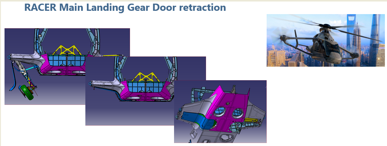
In the framework of Clean Sky 2 the project ANGELA is aimed at developing the landing gear system of the Airbus Helicopters RACER flight prototype (Figure 1). The development of the compartment doors are part of ANGELA and RACER program.
1.1. Landing Gear Outlines
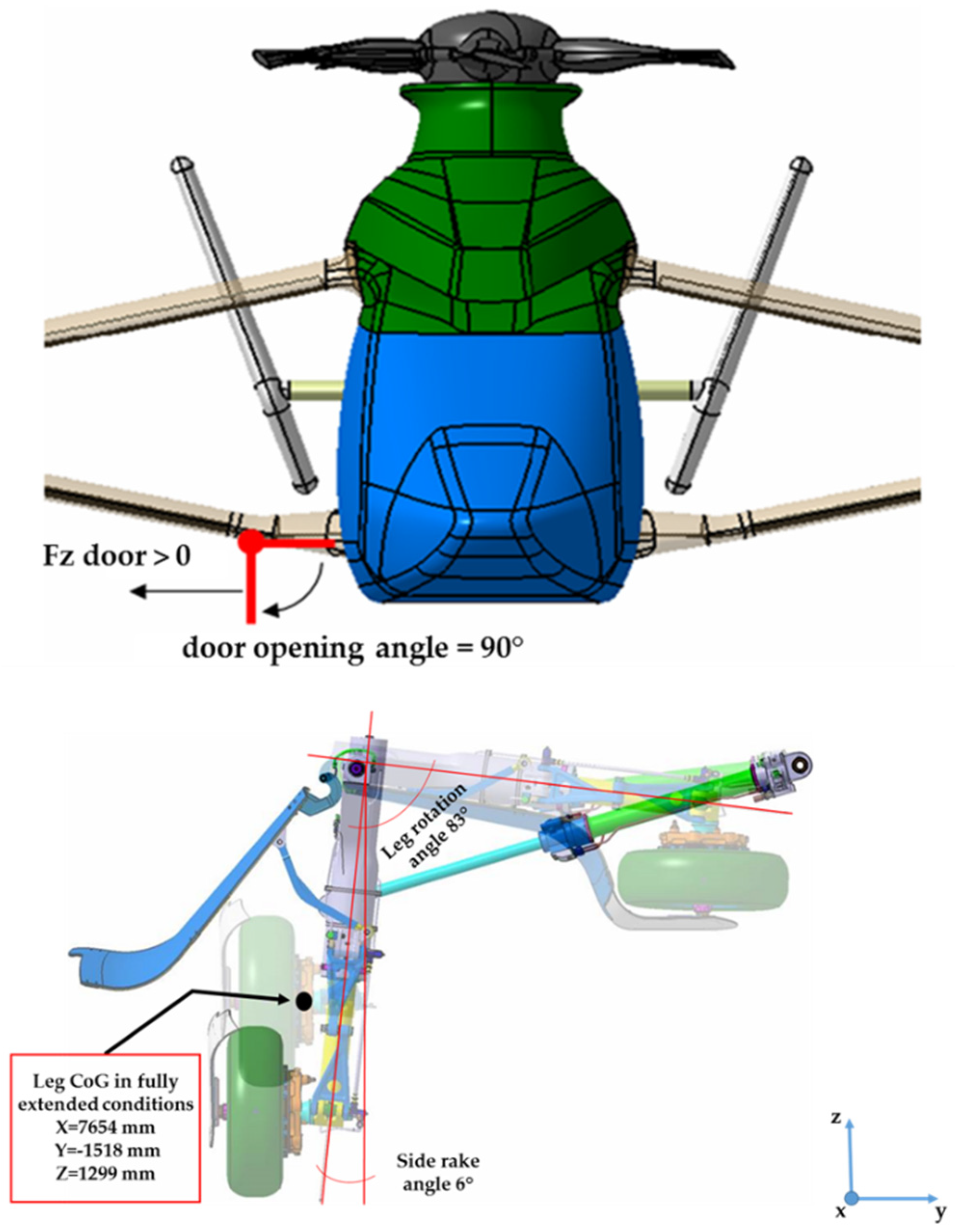
The landing gear system of the RACER is a tricycle wheeled type and oleo-pneumatic shock absorber landing gear system. It is composed by the following systems/sub-systems/equipment shown in Figure 2:
- ▪
- Two Main Landing Gears (each Main Landing Gear (MLG) with the capability to install a leg fairing);
- ▪
- One Nose Landing Gear (with the capability to install a leg fairing);
- ▪
- A retraction system for each Landing Gear;
- ▪
- A hydraulic brake for each Main Landing Gear;
- ▪
- A Wheel (rim and tire) for each Main Landing Gear;
- ▪
- Two Wheels (rims and tires) for the Nose Landing Gear;
- ▪
- Landing gear compartment doors for each MLG and for the NLG (Include the mechanism driven by the landing gear to open / close them).
1.2. Trap Doors General Requirements
The main landing gear trap Doors are integrated and flush with the RACER wing external loft when the Landing Gear System (LGS) is retracted.
Smoothness and flushness requirements during high velocity are the drivers to achieve low drag that contributes to achieve the performances of the fast rotorcraft [1,2]. In addition, the structures should be able to react the flight loads during the LGS extension phase in maneuvers and up to VLO (Velocity Landing Gear Operating), thereby preventing any failure.
For all this reasons, the “pre-bow” door architecture sufficiently preload in a retracted condition was considered as one of the possible candidates in ensuring the smoothness/flushness and strength requirements in all the flight conditions. The identification of the final bow door shape able to guarantee the aerodynamic requirement during high speed mission is an iterative process combining external aerodynamic load, internal bay actuator pre-load, door stiffness and strength. With no specific literature studies and no relevant similar industrial experiences, Rapid and cost-efficient rotorcraft (RACER) is indeed the only fast rotorcraft, having a landing gear trap doors as part of the lift surfaces. Therefore, a specific and dedicated numerical method development was planned in order to setup a tool able to support the design phase.
Prior to consider the pre-bow configuration other design solutions were investigated by the authors. In particular:
- Stiffened door panel and hybrid metal-composite door panel design solutions were not compliant with the target weight, for this reason was rejected.
- Design solution based on a different kinematic configuration was discarded due to the absence of appropriate space in the landing gear bay.
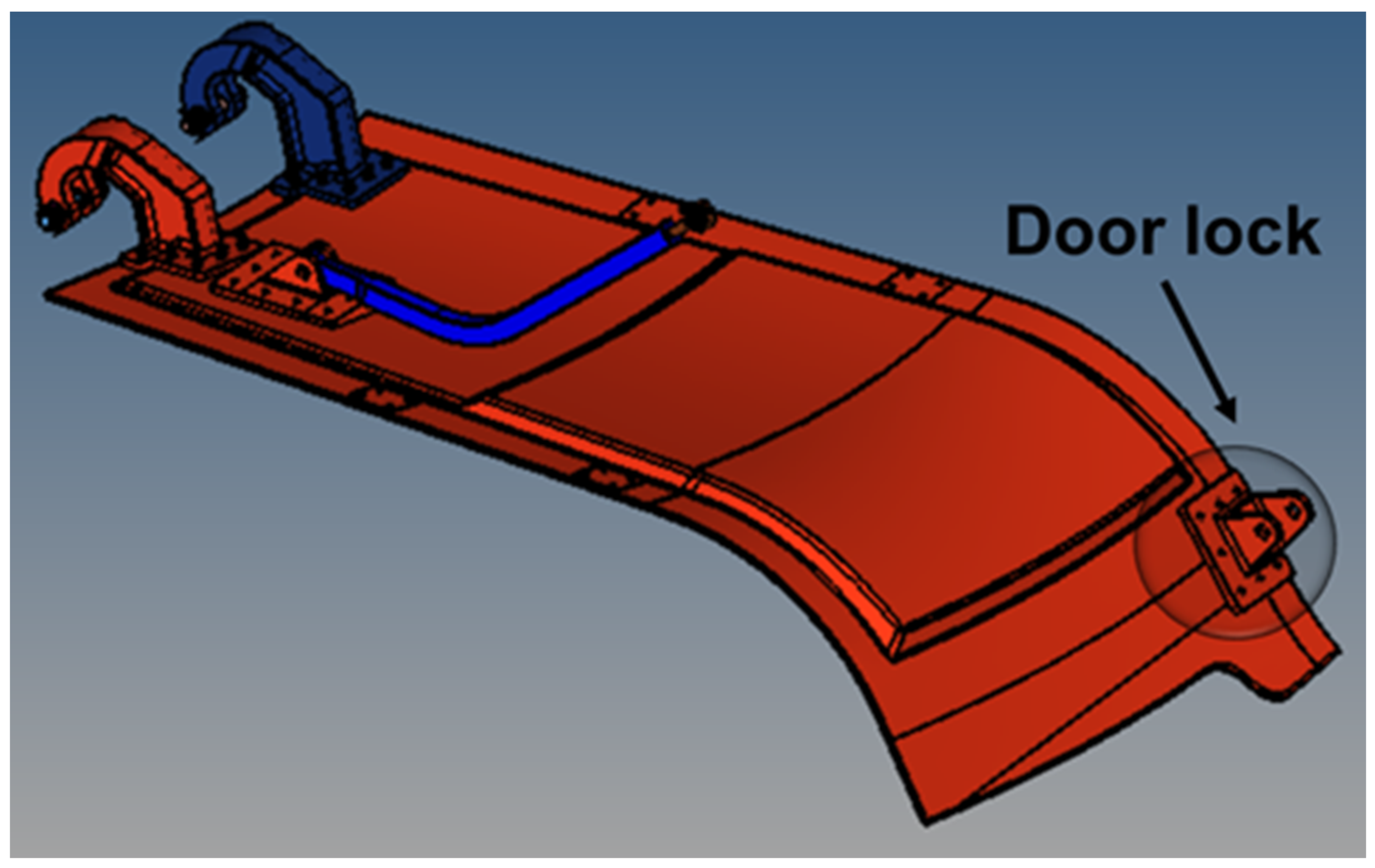
- Design solution considering a door lock mechanism at door free side of the panel door was discarded, since it did not permit the flushness requirement fulfillment Figure 3.
1.3. Main Landing Gear Trap Doors Outlines
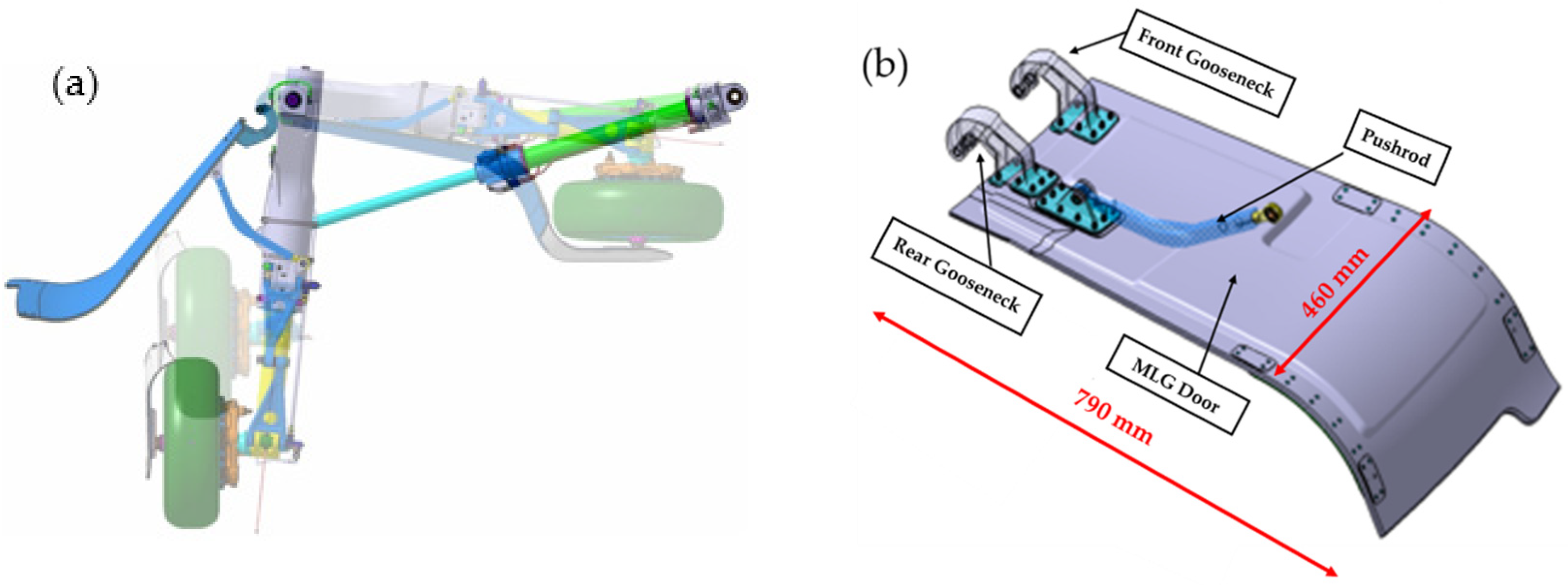
In some studies [3] the main complexity of landing gear design is the identification of shock absorber characteristics, in order to match the airworthiness and aircraft requirements. Other studies [4,5] have demonstrated that the loads under impact and validation in non-linear conditions represent another challenge in landing gear design, in normal, and off nominal flight conditions, such as crash-landing ones. The design of the Racer trap doors requires stiffness considerations and the coupling effects of aerodynamic and inertial load with structure behavior [6]. In the literature, only few examples exist of landing gear trap doors optimization. Arnold and Gambling [7] setup a non-linear analysis for the optimization of landing gear lock mechanism. Viduez et al., [8] used a surrogate model for the identification of the Airbus 350 landing gear doors in warped configuration. In addition, in this case, the aerodynamics drives the design, not only from strength point of view, but also for the effect on the functionalities (i.e., comfort, and drag). In military sector, the optimization of landing gear door of F-22 [7] is another example on numerical method and analysis (Hyperworks® based) more devoted to reduce the cost and the assembly time. AIRBUS-RACER main landing gear is a direct landing gear cantilever type, equipped with carbon fiber epoxy sandwich doors, hinged to the helicopter, by using metallic gooseneck on airframe side.
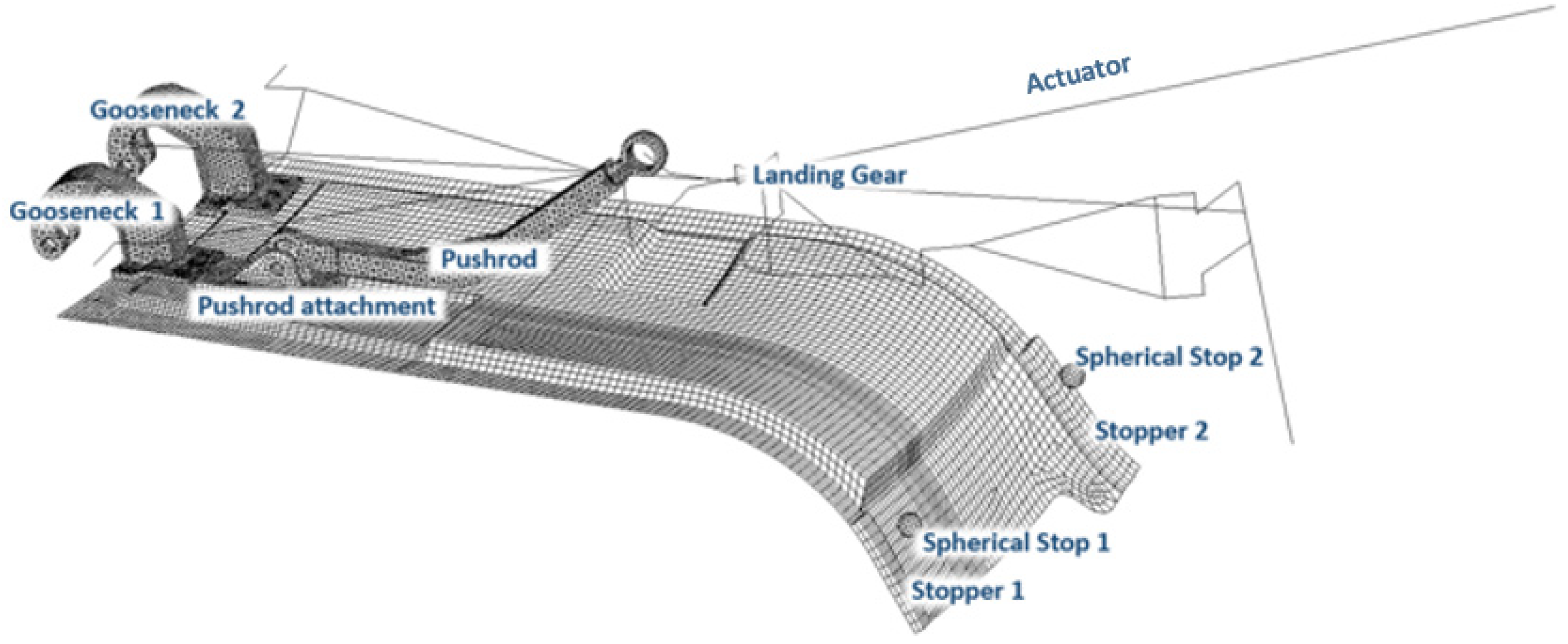
The actuation system consists of a dedicate side-brace actuator attached on landing gear leg; thus, the door is connected to landing gear by means of a push rod link. The landing gear system and the Main Landing Gear (MLG) door are shown in Figure 4. within its main components.
In retracted condition, a forced displacement is generated by the actuator trough the locking system, the force is reacted over helicopter frame, by four stoppers placed on each door sides (two stoppers for the right door and two stoppers for the left one).
2. Methods
The procedure described is based on the determination of the so-called “deformed opposite configuration” of the door that is the “virtual” deformed door configuration, obtained by adding to each Finite Element Method un-deformed node position, the opposite displacement carried out by applying the flight loads on the constrained trap door. Therefore, after a series of appropriate repositioning of the main components, in order to have a real description of the landing gear kinematic, the new pre-shaped door has been verified in terms of closure and flushness.
The main tool used in this work is MSC Nastran (MSC Software, Newport Beach, US) SOL 400 since it is able to include large displacements effects, deformable contact bodies, and definition of the load history. In non-linear analysis load history must be correctly defined because the sequence in which the loads are applied. This can significantly affect the final configuration of the structure; in this specific case, the actuator preload must be defined in a preliminary phase and then aerodynamics loads must be added, in order to correctly describe the real flight situation.
2.1. Geometrical and Numerical FEM Model Description
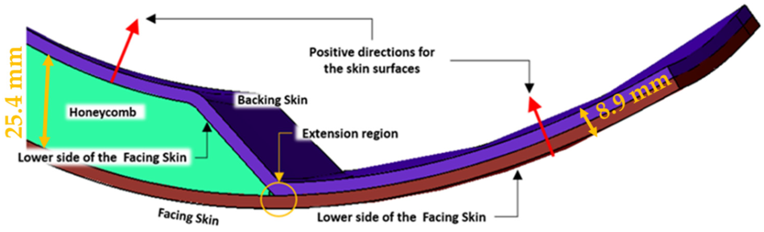
In this section the approaches used to create the finite element models for MLG are described. In particular, the MLG structure is characterized by the following components, as shown in Figure 5:
- –
- A facing skin in composite material;
- –
- A backing skin in composite material;
- –
- An intermediate region filled by honeycomb material to properly space the two composite skins in the different parts of the structure.
The metallic components (i.e., gooseneck, push rod attachment) connecting the landing gear doors to the airplane structure or to the landing gear itself are present in the model. Bolts are used to connect metallic parts to the composite structure.
Specific modelling solutions have been used to simulate the different part of the structures.
2.2. Composite Panels
The composite panels have been modelled by using two-dimensional (2D) shell linear elements. The grid points of the composite panels have been positioned at the lower side of the facing and backing skins.
In this condition, the two skins must be repositioned by defining the location of the panel’s mid-surfaces by using the offset data in the connection entry of the 2D elements (ZOFFS field in CQUAD4 and CTRIA3 entries). This strategy avoids the use of the Z0 field in the PCOMP entry, in order to fully exploit the concept of offset both, in linear and nonlinear analysis.
Care must be taken in the definition of the normal vectors to the 2D elements; in fact, the stacking sequence is defined by the layer positioned at the bottom of the element (in the opposite direction with respect to the normal of the element at a distance that is the half the thickness). Elements have been defined, in order to obtain a normal oriented as in Figure 2.
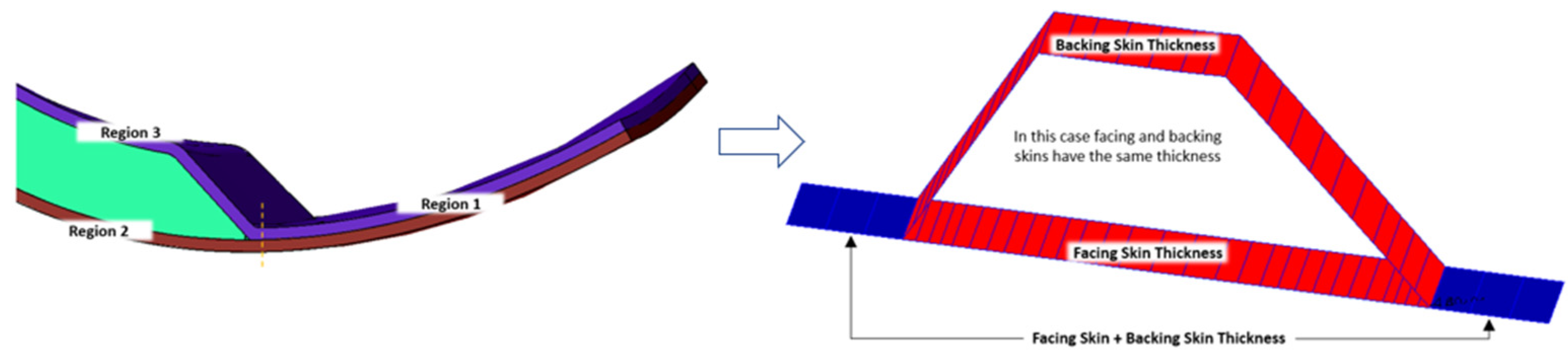
Furthermore, in order to establish the continuity between backing and facing skins a transition region has been created extending the lower surface of the backing panel up to the lower surface of the facing panel. This schematization determines the creation of three different 2D regions (see Figure 6) with different thicknesses associated:
- –
- Region 1
The thickness is equal to the sum of the facing and backing skins thicknesses. Offset is defined as .
- –
- Region 2
The thickness is equal to that one of the facing skin. Offset is defined as .
- –
- Region 3
The thickness is equal to that one of the backing skin. Offset is defined as .
Finally, the FE model has the following characteristics:
- –
- The stiffness of the composite regions is represented in a very detailed way, namely the thicknesses are the same of the ones reported in the CAD model.
- –
- The congruency of the lower surfaces of the different regions is satisfied.
- –
- The honeycomb region is thicker than in the drawing. However, it does not significantly affect the stiffness of the structure, due to its low elastic properties with respect to the composite material ones.
In Figure 7 is shown a schematic view of the sections of CFRP sheet offset.
2.3. Honeycomb
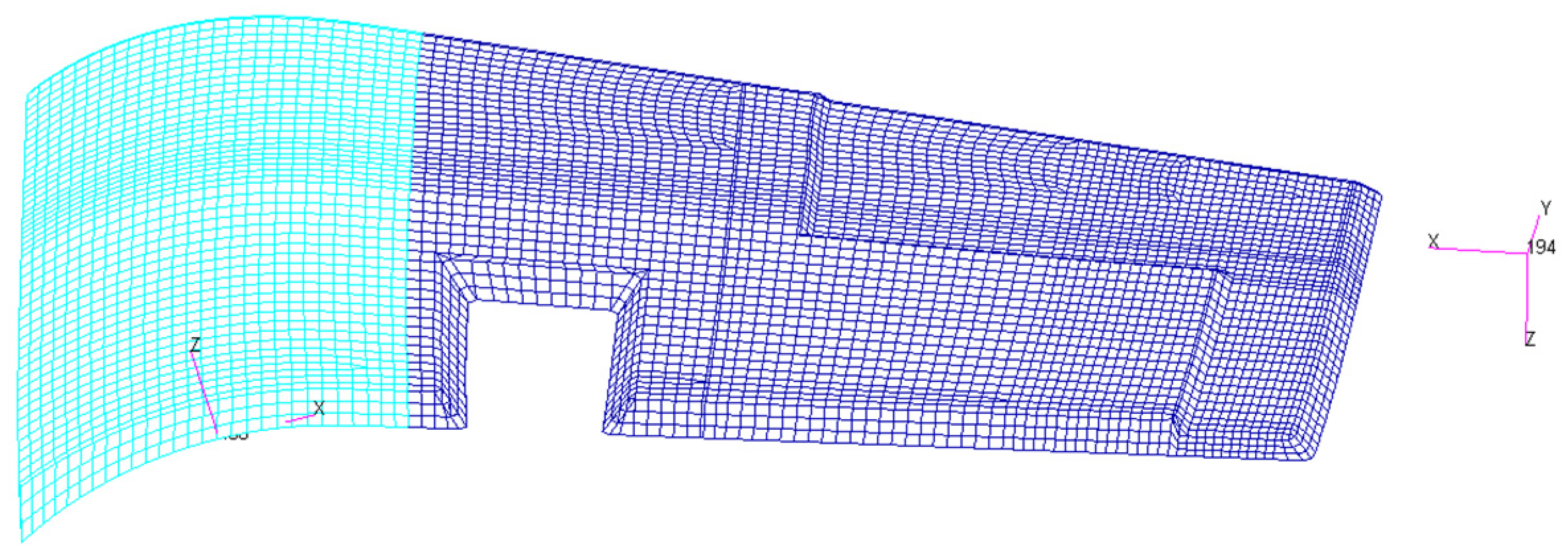
Concerning the honeycomb material, it has been modelled by using three-dimensional (3D) anisotropic linear elements (with orthotropic properties). MLG structure presents both flat and curved areas. The appropriate reference coordinate frames were defined, in order to avoid the definition of a material coordinate system linked to the one of the elements. The rigorous solution for the curved parts would have been to construct a reference frame for each element. However, in order to simplify the model definition and the structure of the input file, the following solution was adopted:
- –
- For the flat or nearly flat regions, a unique material reference system was considered (dark blue part in Figure 8); no approximation has been introduced in this case. This region is made by metallic honeycomb.
- –
- Considering that the curved regions are characterized by a constant curvature, due to the limited extension, it was defined by just one material reference system, positioned on the central area of the curved part, and locally tangent to the surface curvature (cyan part in Figure 8). This region is made by phenolic honeycomb.
This choice introduces some approximations into the honeycomb material behavior representation. However, it is considered a valid compromise between the numerical representation and pre-processing phase time reduction. In this way, the generated Nastran input file is more readable and more easily debugged in case of errors during the analysis phase. Furthermore, it is important to underline that this approximation is legitimated by the fact that the mechanical characteristics of the honeycomb are very low with respect to the composite ones.
2.3.1. Phenolic Core Mechanical Properties
This section shows the mechanical properties for the phenolic core used for the MLG door. HRH-10 Aramid Fiber Reinforced Honeycomb has been adopted (Nomex, I.MA.TEC, Milan, Italy). Material properties used for the calculation are shown in the Table 1.
2.3.2. Metallic Core Material Properties
This section presents the allowables for the metallic core used for the MLG door. Aluminum 5052 Corrugate Honeycomb allowable has been adopted (HexWeb® Aluminum Flex-Core®, Hexcel Corporation, Stamford, CT, USA). Material properties used for the calculation are shown in the Table 2.
2.4. Metallic Attachments
Considering the high sensitivity of the structure global stiffness to the metallic fittings, a high fidelity modelling assumption was adopted to minimize the approximation. Indeed, all metallic parts have been modelled with 3D elements with isotropic behavior (see Table 3).
Main components have been meshed by using TETRA linear elements; for some of them, it has been possible to use of iso - mesh allowing a reduction of the number of elements.
2.5. Bolt Connections
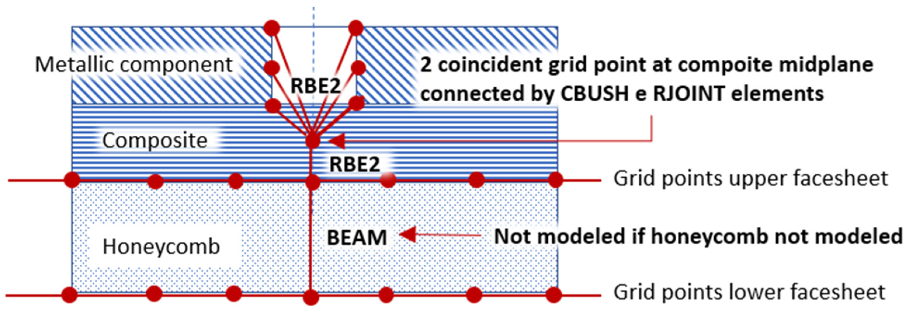
Metallic parts are connected to composite regions by bolts, with a diameter of 3/16”. The general FEM fastener representation has been used to model them. This general modelling solution has been applied (and appropriately modified) to the connection between the generic metal component and the sandwich structure present in the doors to be analyzed. The following modelling solution has been adopted (see Figure 9):
- –
- A BEAM element, which diameter is the one of the bolts reported on the CAD model, connects the two points representing lower and upper facesheets (composite skins) of the honeycomb.
- –
- A RBE2 element connects a point (independent grid point) located at the midplane of the upper honeycomb facesheet (backing skin) to the grid points representing the lateral surface of the bolt accommodation in the metallic component.
- –
- A second point, coincident with the previous one, is create at upper honeycomb facesheet midplane location. It is part of a RBE2 element that connects it to the upper grid point of the BEAM element.
- –
- A Cartesian coordinate system is created as the analysis coordinate frame to the two coincident grid points. Its Z-direction is coincident with the axis of the bolt while one of the axes in the bolt section is oriented as the X of the coordinate system associated to the composite material.
- –
- A BUSH element connects the two coincident grid points in their common translational directions. The stiffnesses K1, K2 and K3 of the BUSH element are properly evaluated (using Huth Formula) according to the metallic and composite parts thicknesses and material properties. The analysis coordinate frame associated to the two coincident grid points has been used as the element coordinate system associated to the generic BUSH element.
- –
- Referring to the above coincident grid points, the rotational degrees of freedom associated to the directions of the common analysis coordinate system normal to the bolt axis, are rigidly linked by RJOINT element.
Note that the bolts located in the regions of the composite structure where honeycomb is not present, are modelled without the BEAM element and the lower RBE2 element refers directly to the grid point representing the facing and the backing composite skins.
2.6. Spherical Joints Modeling
Most of the metallic components are connected by spherical joints that have been modelled as follow:
- –
- A RBE2 element connects the point at the center of the spherical joint to some points in the first component.
- –
- A second RBE2 element connects a new point at the center of the spherical joint to some points of the second component.
- –
- The two coincident grid points are connected in the translational degrees of freedom by using a RJOINT element.
- –
- Care must be taken in case the component is connected to the structure only by two spherical joints (the rod in the MLG door for example). In fact, in this case, the component is free to rotate around its axis. The rotation around the component axis is avoided by introducing this degree of freedom in one of the RJOINT used to describe the spherical joints.
- –
- In some cases, one of the two RBE2 element is substituted by a node of a flexible component (a BEAM representing a pin for example) at the spherical joint center.
2.7. Stoppers Modeling
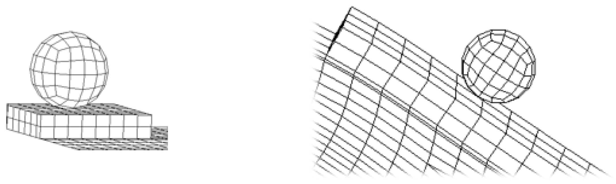
Stoppers have been modelled in a schematic way without considering their actual configuration. Indeed, only the stoppers’ actual position has been considered, in order to simulate correctly the contact conditions. The following modelling solution has been considered. A spherical solid has been modelled representing the original configuration of the stopper. Its axis and lower part correspond to the real stoppers. Then, a region of the composite structure below the stopper has been identified and extruded towards its normal direction, in order to create a solid structure that acts as a stop for the stopper. The height of this ledge was imposed to be equal to the local thickness of the composite plus 1 mm. The FE model of the spherical stopper is reported in Figure 10. In order to describe the contact condition between the MLG door and the stoppers, a “node to segment” strategy has been employed.
2.8. Landing Gear Modelling
Since it was not efficient to integrate the detailed model of the landing gear, it was considered a simplified ’rigid’ beam model in which the various components are correctly connected, in order to best represent the possibilities of relative motion between them, as per Figure 11.
2.9. Carbon fiber reinforced plasticdescription
The modeling solutions used for composite can be summarized as follow:
- –
- As already mentioned, the lower surface of the composite has been chosen to build the finite element model of the correspondent regions (OML surface for facing skin and internal surface for backing skin).
- –
- The offset to define the correct position of each laminate has been defined in the finite element entry (CQUAD4 or CTRIA3), not in the field Z0 of PCOMP entries. In this way, using MDLPRM, OFFDEF, LROFF (new parameters available in MSC Nastran), it is possible to take into account correctly the nonlinear effects of the offset.
The composite part of the model is represented in Figure 12 and the stacking sequences are, instead, reported in Table 4.
Carbon Fiber Reinforced Plastic Mechanical Properties
This section presents the lamina properties for material Cytec 977-2A/HTA 2 × 2 Twill used in the door panel skins. The values presented have been provided by MA group and derived from dedicate experimental test campaign. Mechanical properties values shown in the Table 5 have been evaluated in room temperature dry (RTD) environmental conditions.
2.10. Summary of the Final Model
2.11. Boundary Conditions and Constrains for MLG Door
The following boundary conditions and constrains have been applied to the MLG door.
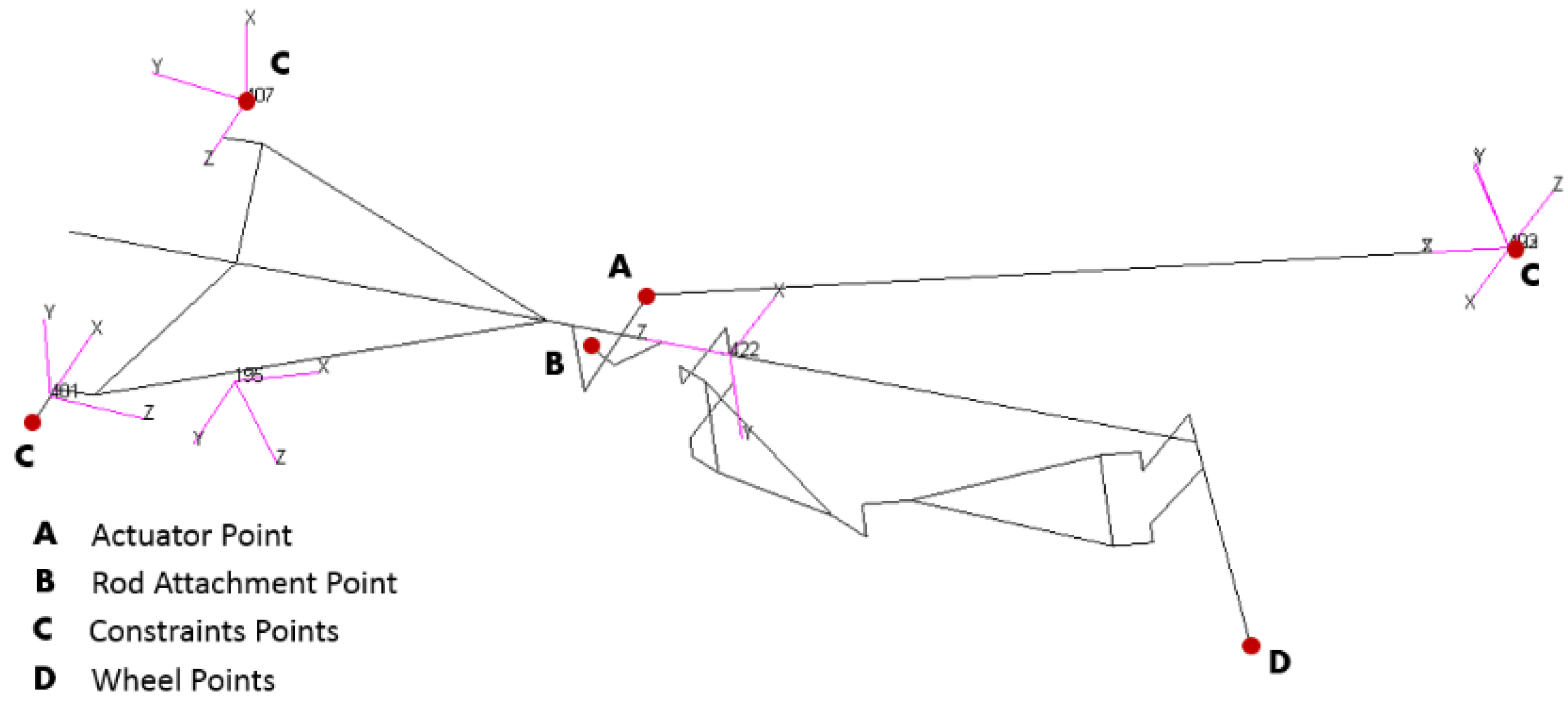
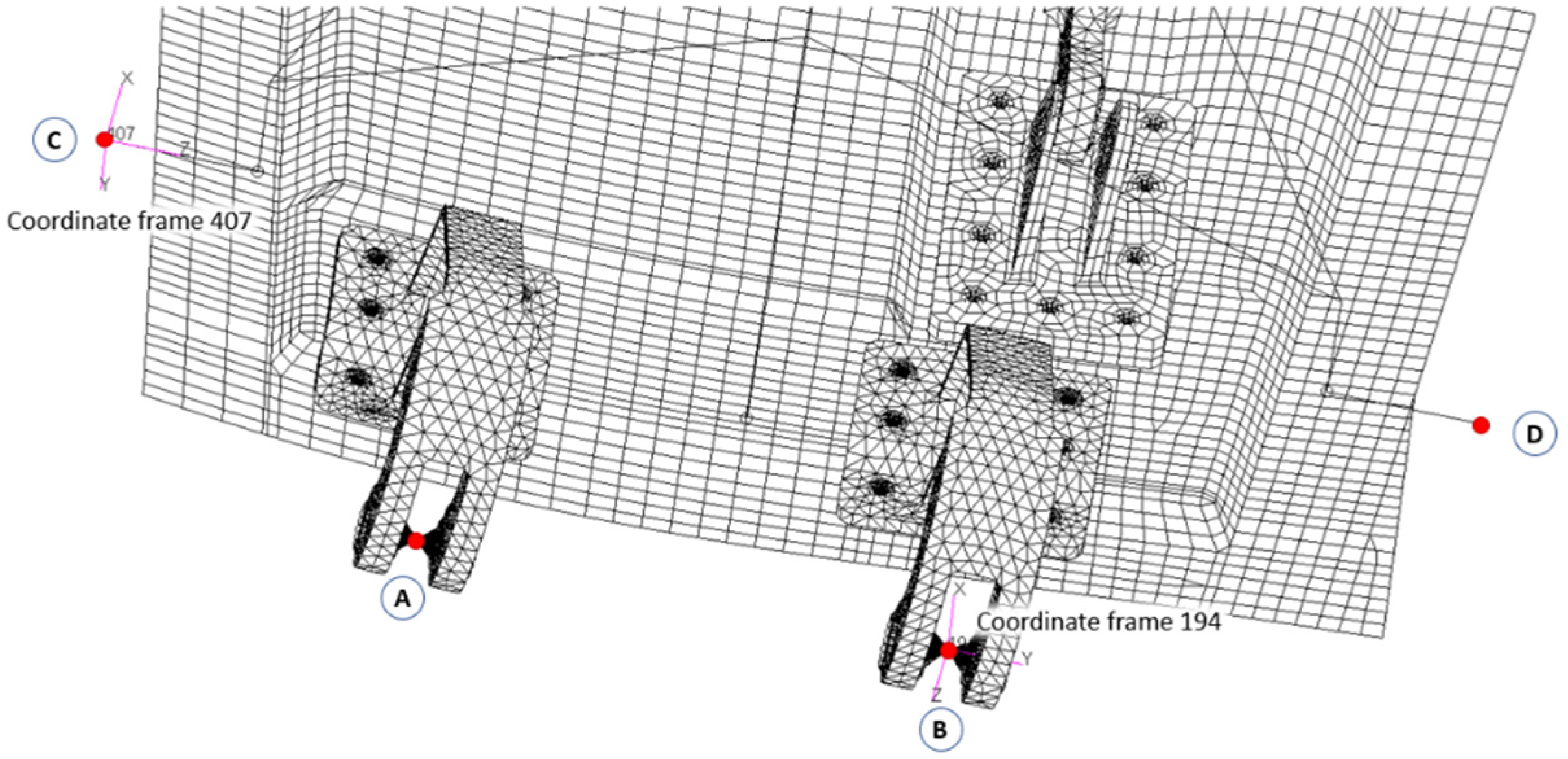
Considering the notations reported in Figure 14, constraints are defined in points A and B relative to the reference system 194, while for points C and D reference 407 is considered.
The following constrains have been applied to the model:
- –
- Point A—Constrained in the degrees of freedom 1 and 3 (It is free to move along the line joining the points A and B).
- –
- Point B—Constrained in all the translational degrees of freedom.
- –
- Point C—Constrained in all the translational degrees of freedom.
- –
- Point D—Constrained in the degrees of freedom 1 and 2 (it is free to move along the line joining points C and D).
Moreover, it is important to remark that:
- –
- The Y axis of the coordinate system 194 corresponds to the line joining the points A and B, and therefore to the axis of the hinges of the goosenecks.
- –
- The Z axis of the coordinate system 407 corresponds to the line joining the points C and D.
Finally, the internal points of the spherical stops have been constrained in the translational degrees of freedom.
3. Methodology to Determinate the Optimal Pre-Shape of the Main Landing Gear (MLG) Door
Smoothness and flushness are the main requirements for the design of the main landing gear trap doors due to the fact these are part of the wing aerodynamic surfaces. The system opens and closes the door during the landing gear retraction-extension phases at low velocity. When closed, the doors must maintain the aerodynamic shape especially during high speed missions. However, during flight, the aerodynamic loads generate an elastic deformation of the Outer Mould Line (OML), generating a non-optimal condition from an aerodynamic point of view. For this reason, the requirement requires that the deformed configuration of the MLG door must not exceed 3 mm, under the combined effect of the aerodynamic suction and the preload generated by the actuator.
The following method has been developed, in order to define an appropriate “pre-shaped” composite trap doors to ensure door stopper engagements and the required smoothness over each aerodynamic condition. It allows to predict the deformation and ensure the most appropriate door “pre-bow” and pre-load, as a consequence to achieve the desiderated aerodynamic shape. The procedure consists of several steps that are described below and will drive the implantation at Digital Mock-Up (DMU) level subsequently.
3.1. Preliminary Step: Determination of the Initial Clearances between MLG Door and Spherical Stoppers
The first step of the procedure consists of determining the clearance due to the combined action of the actuator and the aerodynamic loads, once an initial design of the door is given The presence of an actuator preload leads to the use of a non-linear solution to allow the correct setting of the load history. In fact, the aerodynamic loads act after the actuator has been preloaded by a “pooling load”; the non-linear analyses have been performed by using implicit solver.
An advanced nonlinear analysis SOL 400 including large displacement, deformable contact bodies in a multiple load step sequence has been considered in order to perform the actual loading phase:
- –
- phase 1—Actuator preload
- –
- phase 2—Aerodynamic load and ‘actuator preload’
The final door pre-shape is obtained by considering the opposite of the deformation obtained by applying Actuator preload + Aerodynamic load with external surface in OML condition.
The initial condition of the nonlinear simulation is to consider the door completely closed (and thus the landing gear completely retracted) and the actuator at its minimum length (length of the bar named actuator in Figure 13).
Thus, two load increments have been created: in the first step an actuator nominal load has been applied (value given by the actuator characteristics) by using the FORCE1 card of MSC Nastran (follower force); finally, in the second step both the actuator load and the aerodynamic load have been set. The aerodynamic load has been applied on the OML nodes by using the PLOAD4 card in MSC Nastran.
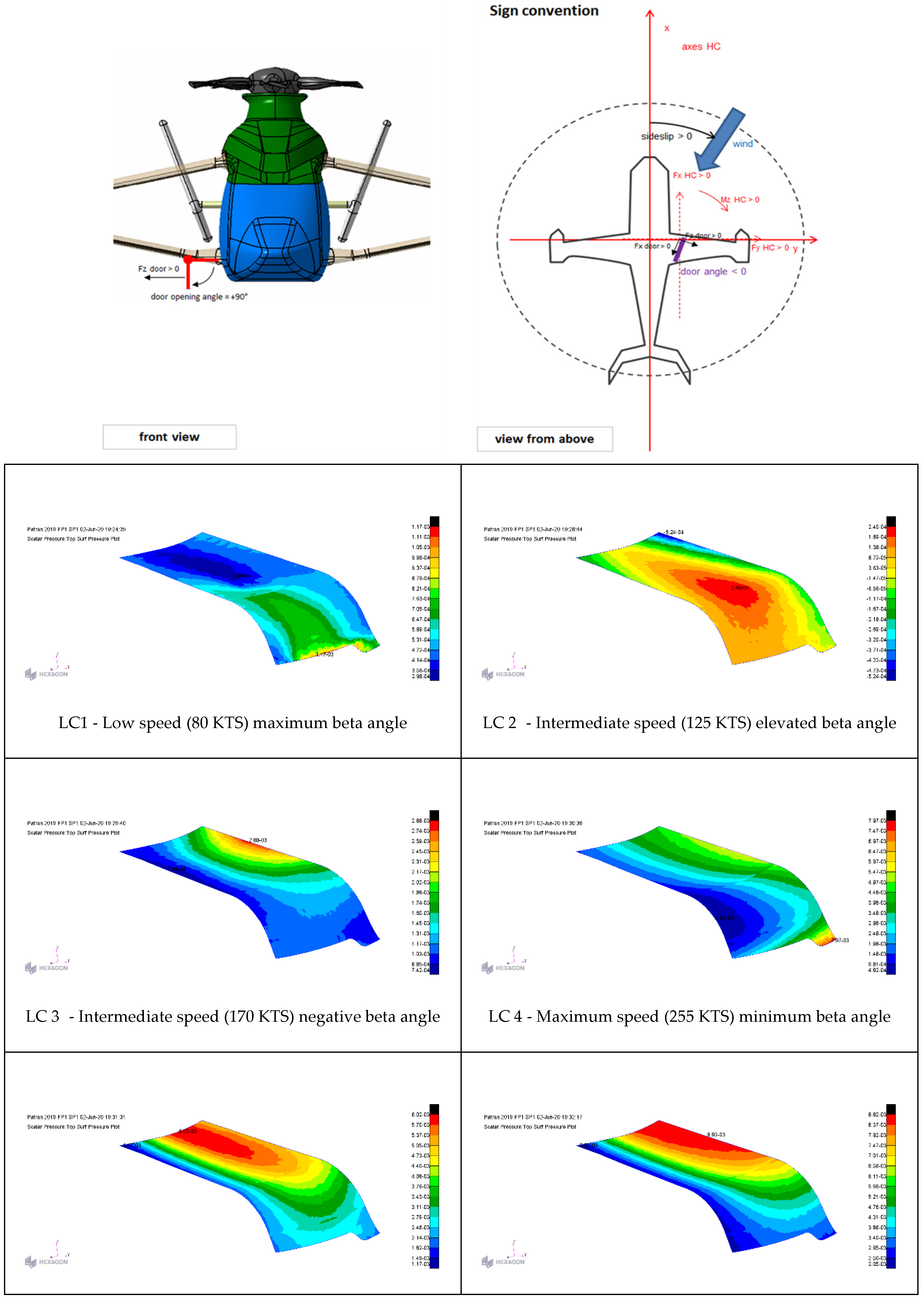
Load Conditions
Six different load conditions have been provided by AIRBUS Helicopters (see Table 7).
Dynamic pressure distributions at different helicopter velocities and at different pitch and slip angles have been applied on the door in order to verify the flushness requirements (see Figure 15). The Critical loading conditions have been identified during initial simulations. LC-6 causes the highest clearances between the MLG door and the spherical stoppers.
At the end of the second load increment, the MLG door results to be fully open and the following clearances between the door and the spherical stoppers (refer to Figure 2 for the notation) have been found:
- –
- Clearance spherical stopper 1: 9.672 mm;
- –
- Clearance spherical stopper 2: 38.023 mm.
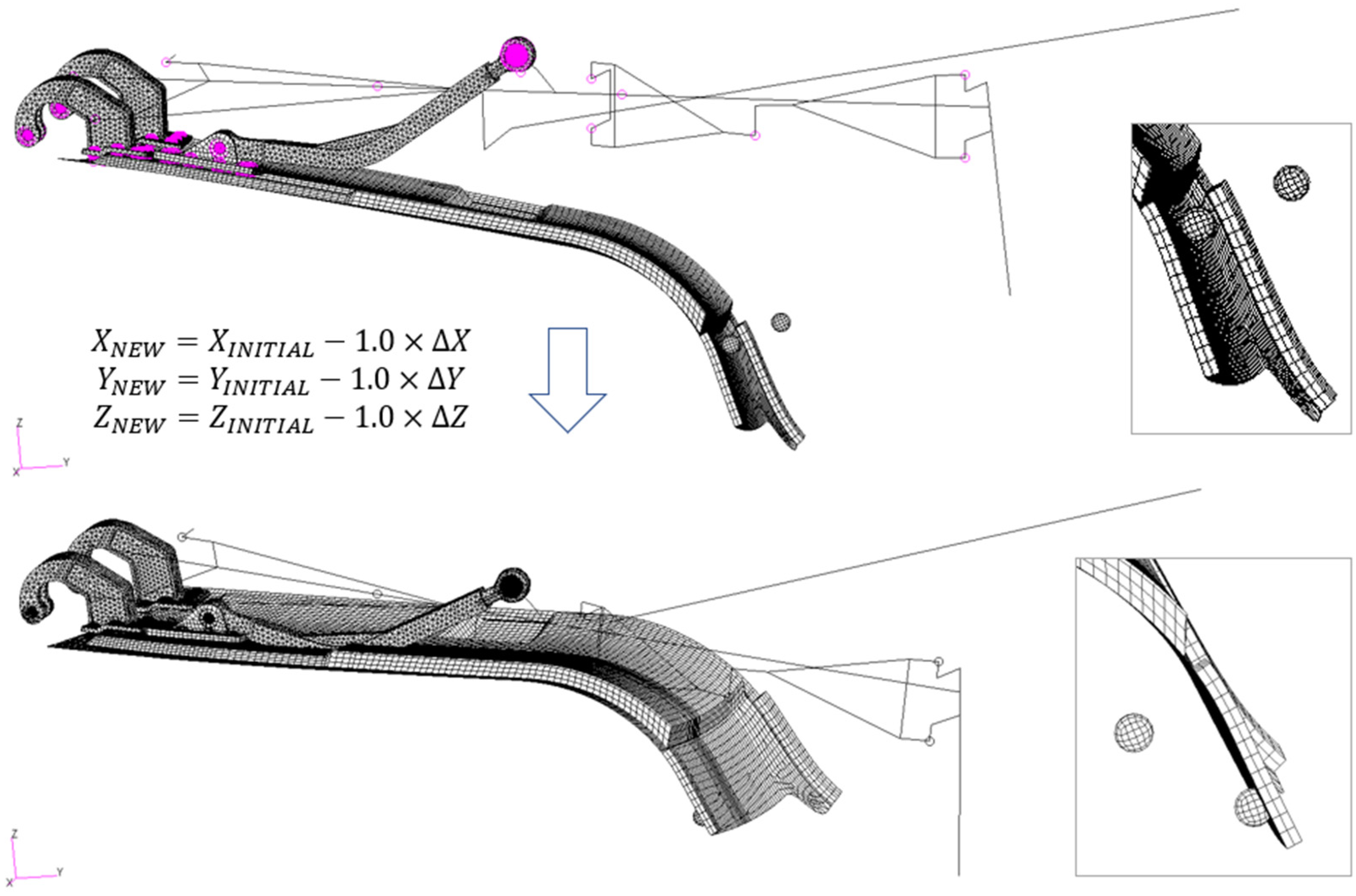
3.2. Step 1: Determination of the “Opposite Deformed Configuration”
The target of the procedure is to create an OML surface that compensate the deformation determined by the critical manoeuvres and aerodynamic load condition maintaining the doors closed over each aerodynamic condition. The purpose of the first step is to identify the so-called, “opposite deformed configuration”. The first modified shape of the door is obtained by adding the opposite of the calculated displacements to the original coordinates of each node in the model, as per Figure 16; this operation has been performed by using the “Results Utilities” of the pre-processor Patran.
The landing gear configuration results are modified by applying the critical load condition and modifying the coordinates of the nodes of the model by the opposite of the corresponding deformation. It is no more in its initial configuration. In order to simulate accurately the landing gear mechanism, the current landing gear finite element model has been totally replaced by its original configuration.
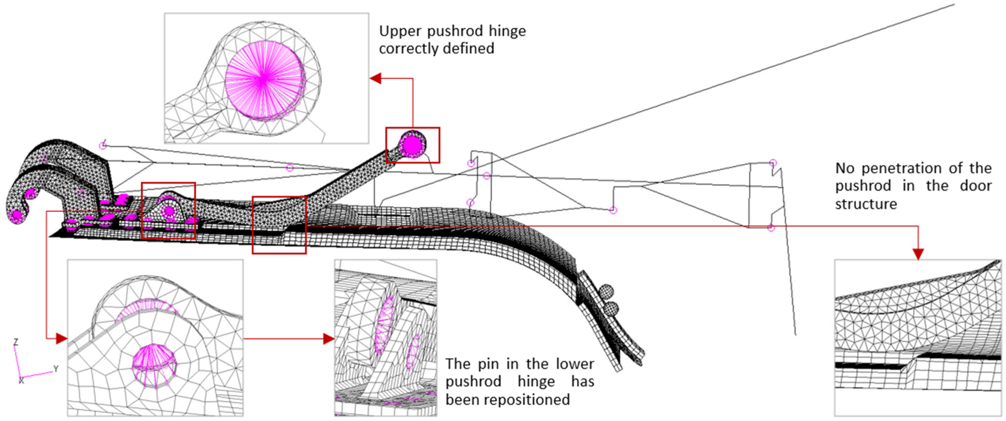
Others important features should be considered. Indeed, the shape modification generates unrealistic deformations and distortions in the push-road as shown in Figure 16. A penetration of the push-road into the door emerges. In order to eliminate any of the deformations in the pushrod, its current configuration is replaced by the initial one. This implies that the configuration of the pushrod must be repositioned in order to guarantee that:
- –
- The upper spherical hinge that connect it to the landing gear, must be relocated in its initial configuration to be congruent with the connecting part of the landing gear.
- –
- The location of the lower spherical hinge must be congruent with the deformed configuration of the pin of the pushrod attachment.
All these changes must be carried out by ensuring that the plane of symmetry of the pushrod remains. These actions are totally executed in the graphical pre-processor (MSC Patran in this case).
Furthermore, other issues must be resolved before going forward. In fact, due to deformation and coordinates modifications:
- –
- The grid points that define the RJOINT elements of the push-road attachments are no more coincident. One of the two grid points defining each of them must be moved to the location of the other.
- –
- The end grid points of the pin in the pushrod attachment must be aligned with the centre of the lower hinge of the pushrod.
- –
- The centres of the hinge of the goosenecks must be relocated at the position of the corresponding constrained grid points.
Finally, the absence of clashes between the various components of the door must be verified. Thus, the finite element model is now ready for the following step.
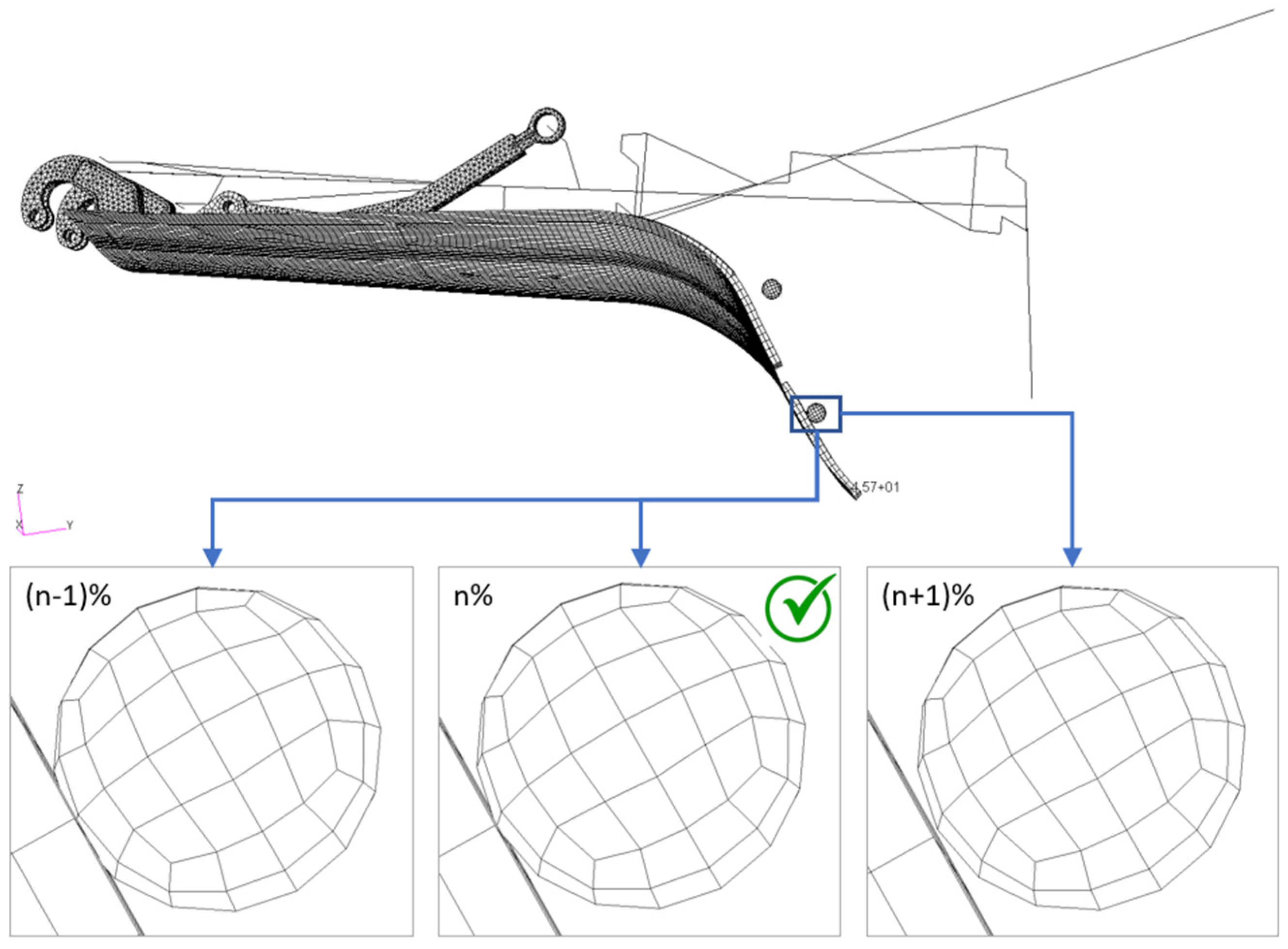
3.3. Step 2: Actuator Extension to Identify the Incipient Contact of One of the Two Stoppers
The current position of the stoppers is not realistic. In fact, they are positioned outside the helicopter. Thus, it must be modified in order they come back internally. The purpose of this part of the procedure is the definition of a door configuration, by which both the stoppers are inside the helicopter, and at least one of them is in an incipient contact condition with door FE model. Moreover, in this step of the procedure, the extension of the actuator is determinate as well.
A rotation around the goosenecks axis (the Y-axis of the coordinate system 194, see Figure 14) in the opening direction is applied in order to obtain a door rotation. The total rotation has been chosen so that the door results to be fully opened (contact with stoppers is eliminated) and stoppers are into the helicopter. A nonlinear simulation using the MSC Nastran SOL 400 has been performed and the “incipient contact deformed configuration” is identified by verifying the deformation of the structure at the different load increments, in order to detect the one (%n) in which the first contact between the door and at least one spherical stopper is achieved (Figure 17).
The OML surface of the identified configuration (that one corresponding to load condition n%) is the new manufacturing aerodynamic surface of the MLG door, (so-called pre-shaped door configuration). The new finite element model of the door is determined by adding the displacement values to the coordinates of each grid point in the not deformed configuration. However, in order to obtain a suitable and usable model, it must be modified as per step 1 to solve the following issues:
- –
- RJOINT in bolts modelling are defined by non-coincident grid points.
- –
- The deformed landing gear configuration must be replaced by the original one.
- –
- The pushrod deformed configuration must be replaced by the original one. Then, it must be repositioned in order to maintain the congruency with the adjacent components (landing gear and pushrod attachment). It determines also the repositioning of the pin of the hinge in the pushrod – pushrod attachment connection.
Finally, at the end of the procedure, no clashes between the various components of the door must be present.
The situation listed above is schematically reported in Figure 18.
Note that the pre-shaped configuration shows a non-null clearance between the door and one of the spherical stoppers when no loads are applied. This situation is never realized in reality, given that when the helicopter is turned off, the landing gear is down and the door is fully open. Thus, in order to be validated, the FE model, obtained at the end of step 2, is used in the third step to verify that the modified configuration allows:
- –
- the door closure when actuator preload is applied.
- –
- the doors is kept closed when the aerodynamic external load are applied.
Furthermore, it must be verified that the difference between the OML deformed configuration (actuator preload and external aerodynamic loads) and the pre-shaped OML configuration is within AIRBUS flushness requirements.
3.4. Step 3: Check of the Door Closure and OML Flushness
The preliminary analysis in which actuator preload and aerodynamic loads are applied are re-executed using the finite element model built in the previous step. All six aerodynamic load conditions are considered separately. The objective of this step is to verify that the pre-shaped configuration of the door allows its closure in all the aerodynamic loading conditions and the flushness requirement asked by AIRBUS as well. The results are reported in next paragraph.
4. Results
Each of the load conditions, applied to the ‘pre-shaped’ door, determine a deformed configuration for the OML surface. A deviation exists between the deformed OML surfaces with respect to the original OML configuration. As mentioned in the previous paragraph, the requirement is that the maximum deviation between the two surfaces must be lower than 3 mm. The threshold value has been defined as the maximum value that ensures acceptable drag so that the helicopter’s performances are not penalized, especially at high velocities.
This paragraph shows the main results in terms of the difference between the original and the pre-shaped OML door closure and the flushness requirements.
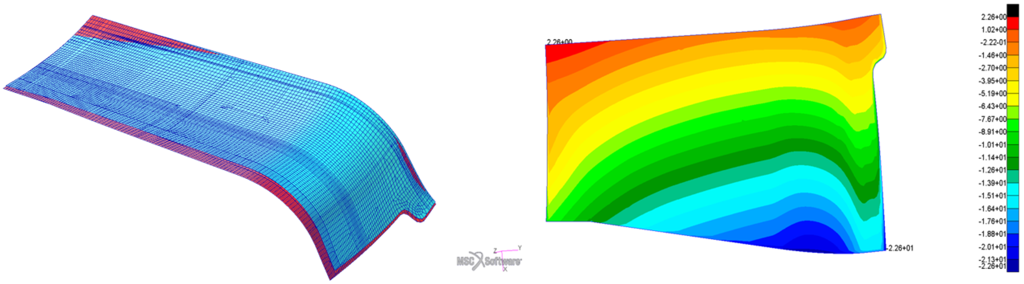
The difference between the original OML and the pre-shaped one is represented in Figure 19. In particular, the left figure reports the two OMLs over posed and coloured by different colours: the cyan door represents the original OML, namely the use at the beginning of the procedure, whereas the red one is the final pre-shaped configuration. Note that the pre-shaped OML is positioned below the original OML, except for a small region near the gooseneck at the actuator side of the door. In order to quantify the difference between the two OMLs, the distance between the two OML has been calculated In particular, positive values indicate that the pre-shaped OML is positioned above the original one and vice versa. The contour plot is reported on the right of Figure 19: the maximum deviation between the two configurations is equal to 22.6 mm in the region near the left stopper.
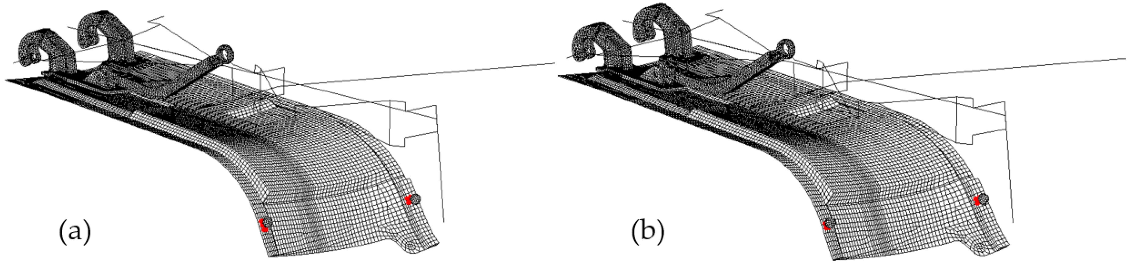
Then, a crucial feature to be verified is the door closure. In particular, this capability should be verified both when only the actuator preload is applied and when both the preload and the aerodynamic load are acting on the door as well. In Figure 20 we report the contact status (red markers) at the last load increment of both the actuator preload (Figure 20a) and the combined (preload + aerodynamic load) load (Figure 20b) for the worst aerodynamic condition LC-6: in both cases, the door results to be in contact with both spherical stoppers. This check has been repeated for all the aerodynamic load conditions. The door is evaluate to be always closed (not reported here for sake of brevity).
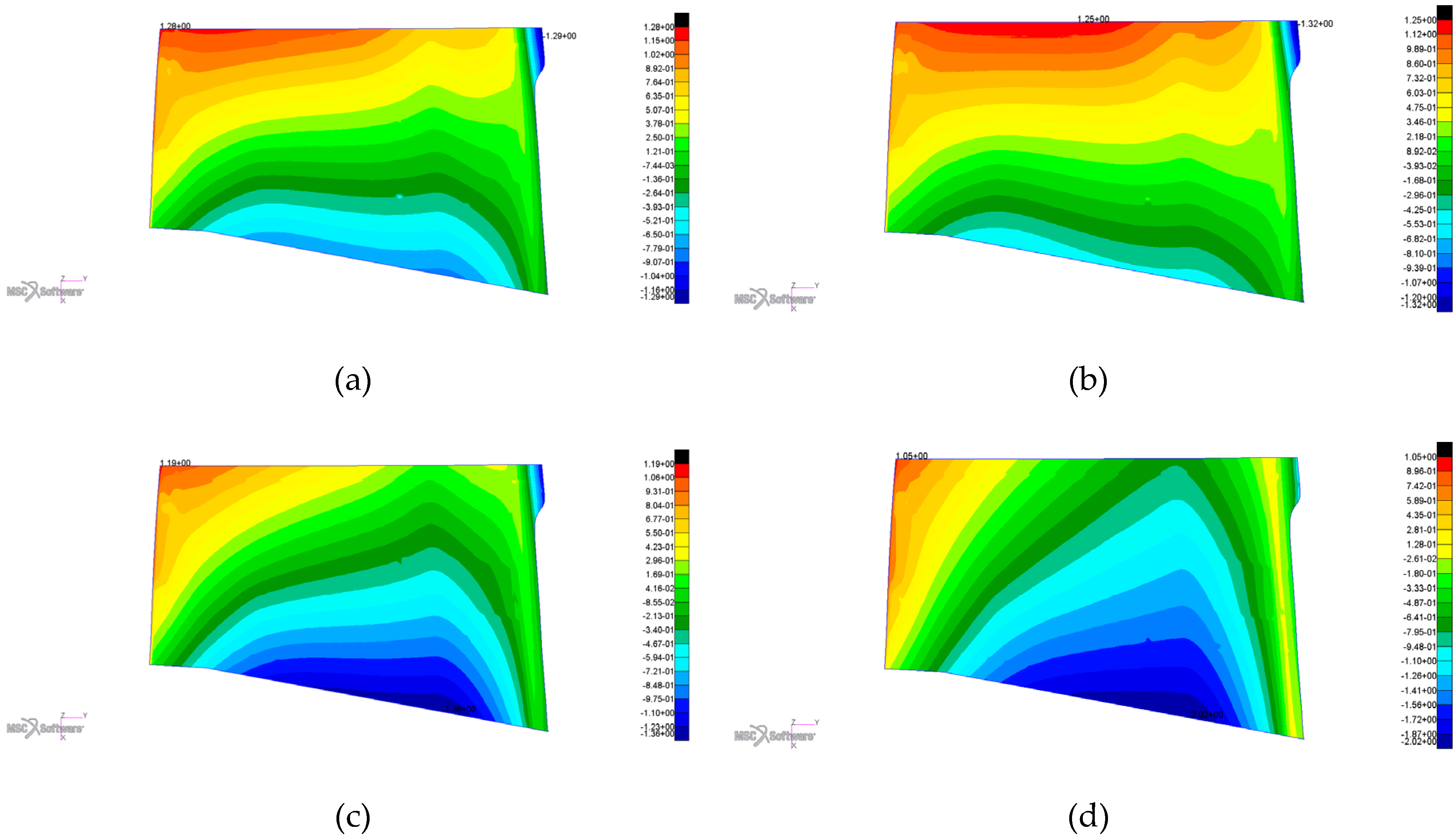
Finally, we calculated the flushness after the application of the preload and the aerodynamic load as the distance between the deformed OML pre-shaped surfaces (deformation due to the combined effect of preload and aerodynamic load) and the unloaded pre-shaped OML.
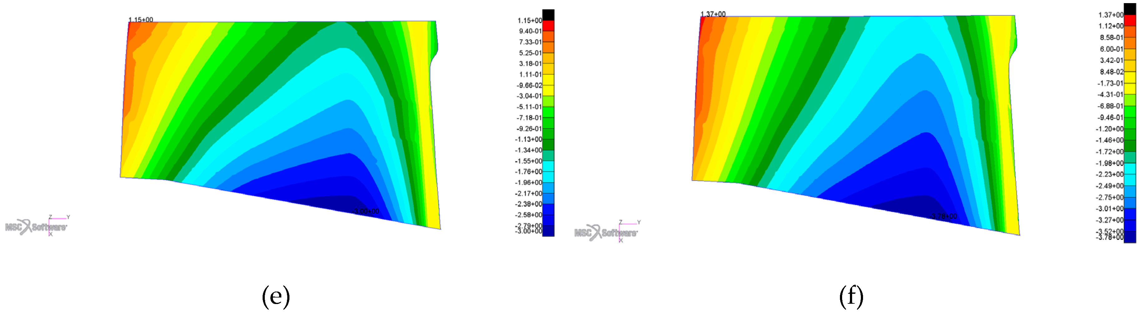
Figure 21 shows the calculated values with the relative sign on the original OML surface by using fringe plots; the verification has been carried out for each of the six aero-load conditions. The sign provides an indication of the relative positioning between the deformed and the original OMLs; Negative distances indicates that the OML deformed surface is external with respect to the original OML surface whereas positive distances indicate that the OML deformed surface is internal to the original OML configuration.
Finally, the maximum positive and negative values of the flushness are reported in Table 8
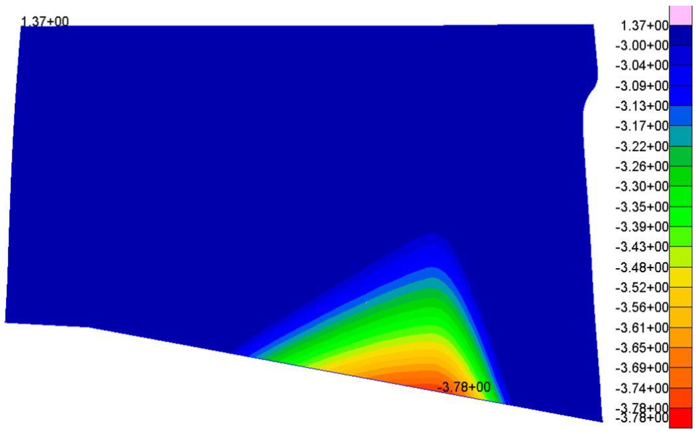
An outward deviation greater than the threshold limit (3 mm) is highlighted for the LC-6 aerodynamic load. However, the affected region is very limited as represented in the fringe plot of Figure 22 with a cut-off at −3 mm. Flushness has been calculated at ultimate loads (not realistic for functional analysis) and it is out of range only in one aero-load condition. For this reason, the flushness requirement has been relaxed and verified only at limited load conditions, resulting verified in all the critical flight conditions.
5. Conclusions
This developed method shows a robust approach to numerically calculating the geometrical manufacturing shape of the MLG door for high speed compound rotorcraft. After a first design approach and strength verification, a crucial point is the precise definition of the OML (aerodynamic surface) of the door, since it is fundamental to avoid penalizing the aerodynamic and the performances of the fast helicopter. The main objective is to determinate the shape of the door so that it assures the complete closure and a maximum flushness of 3 mm (as per AIRBUS technical requirements) under the combined actions of the actuator preload and any aerodynamic load.
This approach is based on the definition of the so called “opposite deformed configuration”, obtained by adding the opposite of the calculated displacements to the original coordinates of each node in the model when only the actuator preload is applied. Thus, a new OML shape has been achieved. Although the door results to be opened when no load acts on it (situation that is never verified in reality), the new shape can verify the closure and flushness requirements when the pre-load is applied and when and aerodynamic loads are added. In addition, it is deemed crucial to verify all the appropriateness of the approach to have a verification of CFD data correlating them with actual flight data. During the flight test campaign loads measurements can be performed by using Skopinski method already employed in past similar application by the authors [9].
Author Contributions
Conceptualization, A.C. and S.O.; methodology, A.C., S.O., M.L. and R.L.; software, M.L., R.L.; validation, All.; formal analysis, A.C., S.O., P.V., M.L. and R.L.; investigation, All; resources, L.D.P.; data curation, M.L., R.L.; supervision, A.C., S.O. and M.L.; project administration, L.D.P.; funding acquisition, L.D.P. All authors have read and agreed to the published version of the manuscript.
Funding
This research was funded by Clean Sky 2 Joint Undertaking under the European Union’s Horizon 2020 research and innovation programme under Grant Agreement No CS2-GAM-FRC-2014-2015 and following extensions. More in details the activities have been funded in the framework of CS2 project ANGELA part of CS2-GAM-FRC.
Acknowledgments
Thanks to Pardoux Pierre Racer Helicopter Architect, Airbus Helicopter and Zakrewski Jaroslaw, Racer Landing Gear System Design Responsible, Airbus Helicopter Polska.
Conflicts of Interest
The authors declare no conflict of interest.
References
- Blacha, M.; Fink, A.; Eglin, P.; Cabrit, P. Clean Sky 2: Exploring new rotorcraft high speed configurations. In Proceedings of the 43rd European Rotorcraft Forum, Milan, Italy, 12–15 September 2017. [Google Scholar]
- Thiemeier, J.; Öhrle, C.; Frey, F.; Keßler, M.; Krämer, E. Aerodynamics and flight mechanics analysis of Airbus Helicopters’ compound helicopter RACER in hover under crosswind conditions. CEAS Aeronaut. J. 2019, 11, 49–66. [Google Scholar] [CrossRef] [Green Version]
- Paletta, N.; Belardo, M.; Di Palma, L. An Automatic Procedure for the Landing Gear Conceptual Design of a Light Unmanned Aircraft. SAE Tech. Pap. Ser. 2013. [Google Scholar] [CrossRef]
- Paletta, N.; Belardo, M.; Di Palma, L. Non-Linear Dynamic Loads Due to the Landing Impact of a Joined-Wing UAV. SAE Tech. Pap. Ser. 2011. [Google Scholar] [CrossRef]
- Di Palma, L.; Di Caprio, F.; Chiariello, A.; Ignarra, M.; Russo, S.; Riccio, A.; de Luca, A.; Caputo, F. Vertical Drop Test of Composite Fuselage Section of a Regional Aircraft. AIAA J. 2020, 58, 1–5. [Google Scholar] [CrossRef]
- Belardo, M.; Paletta, N.; Di Palma, L.; Pecora, M. Structural and Aeroelastic Design of a Joined-Wing UAV. J. Aerosp. Eng. 2014, 27, 93–111. [Google Scholar] [CrossRef]
- Mark, A.; Gambling, M. Efficient Shape Optimization of an Aircraft Landing Gear Door Locking Mechanism by Coupling Abaqus to GENESIS. In Proceedings of the 2009 SIMULIA Customer Conference, London, UK, 13 May 2009; Available online: https://www.grm-consulting.co.uk/images/pdf/papers/05_Abaqus_Coupling (accessed on 12 May 2020).
- Viúdez-Moreiras, D.; Martín, M.; Abarca, R.; Andrés, E.; Ponsín, J.; Monge, F. Surrogate modeling for the main landing gear doors of an airbus passenger aircraft. Aerosp. Sci. Technol. 2017, 68, 135–148. [Google Scholar] [CrossRef]
- Paletta, N.; Belardo, M.; di Palma, L. Evaluation of wing loads during the flight drop test of the italian unmanned space vehicle. In Proceedings of the 5th International Operational Modal Analysis Conference, IOMAC, Guimaraes, Portugal, 13–15 May 2013; pp. 1–12, EID: 2-s2.0-. [Google Scholar]
Figure 1.
AIRBUS Racer (Reproduced with permission from AIRBUS Helicopter Copyright Publisher, 20161).
Figure 1.
AIRBUS Racer (Reproduced with permission from AIRBUS Helicopter Copyright Publisher, 20161).

Figure 2.
ANGELA Main Landing Gear extension-retraction for RACER.

Figure 3.
Main Landing Gear design solution with door lock mechanism.

Figure 4.
(a) Main and Fairing landing gear doors within the actuation system; (b) Main landing gear door by which it is possible to observe the metallic gooseneck connecting the door to the airframe, and the rod linking the door to the landing gear.
Figure 4.
(a) Main and Fairing landing gear doors within the actuation system; (b) Main landing gear door by which it is possible to observe the metallic gooseneck connecting the door to the airframe, and the rod linking the door to the landing gear.

Figure 5.
MLG structure (in blue the backing skin, in red the facing skin and in green the honeycomb). The red arrows represent the normal vectors of the upper and lower skins used to define the shell elements in the numerical model. In this figure, it is possible to observe the extension region used in order to establish the continuity between the two skins.

Figure 6.
Left: The three different 2D regions. Right: FE discretization with shell elements.

Figure 7.
Section of CFRP sheet offset.

Figure 8.
Honeycomb FE model with the material coordinate frames for the flat (dark blue, metallic) and curved (cyan, metallic) parts.
Figure 8.
Honeycomb FE model with the material coordinate frames for the flat (dark blue, metallic) and curved (cyan, metallic) parts.

Figure 9.
Bolt connections modeling.

Figure 10.
Finite Element model of the spherical stopper.

Figure 11.
Landing gear simplified model.

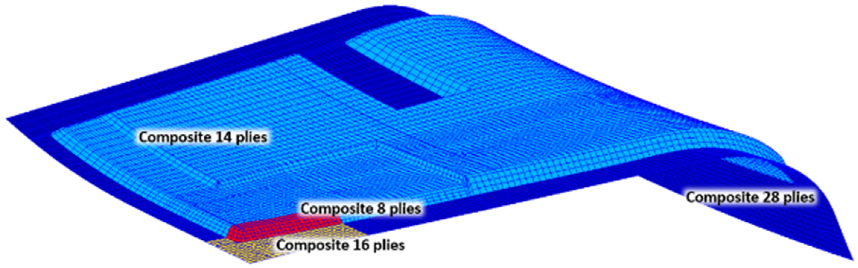
Figure 12.
Composite part of the Finite Element model within the number of plies in each region.

Figure 13.
Final FE model for MLG door.

Figure 14.
MLG constrain points and their output coordinate frames.

Figure 15.
Lower figures are CFD Dynamic pressure (Pa), upper figure specify the Helicopter reference system for the slip angle.
Figure 15.
Lower figures are CFD Dynamic pressure (Pa), upper figure specify the Helicopter reference system for the slip angle.


Figure 16.
Determination of the “opposite deformed configuration”.

Figure 17.
Middle figure: “incipient contact deformed configuration”; left figure: a load increment before the “incipient contact deformed configuration”; right figure: a load increment after the “incipient contact deformed configuration”.
Figure 17.
Middle figure: “incipient contact deformed configuration”; left figure: a load increment before the “incipient contact deformed configuration”; right figure: a load increment after the “incipient contact deformed configuration”.

Figure 18.
Final FE model after the step 2 on which the correct repositioning of all the component and the absence of clashes have been verified.
Figure 18.
Final FE model after the step 2 on which the correct repositioning of all the component and the absence of clashes have been verified.

Figure 19.
Difference between the original and pre-shaped OML. Left figure: in cyan the original OML (before starting step 1 of the procedure) and in red the pre-shaped OML (obtained at the end of step 3). Right figure: Contour plot of the distance between the original and the pre-shaped OML: Positive distance indicates that the pre-shaped configuration is positioned above the original one and vice versa.

Figure 20.
Contact status between the door and spherical stoppers at: (a) final load increment of the actuator preload application; (b) final load increment with preload + LC-6 aerodynamic load. Red markers indicate that the contact is active.
Figure 20.
Contact status between the door and spherical stoppers at: (a) final load increment of the actuator preload application; (b) final load increment with preload + LC-6 aerodynamic load. Red markers indicate that the contact is active.

Figure 21.
Flushness between the OML deformed configuration and the original one: (a) LC-1; (b) LC-2; (c) LC-3; (d) LC-4; (e) LC-5; (f) LC-6.
Figure 21.
Flushness between the OML deformed configuration and the original one: (a) LC-1; (b) LC-2; (c) LC-3; (d) LC-4; (e) LC-5; (f) LC-6.


Figure 22.
Fringe plot of the flushness for the LC-6 condition with a cut-off at -3mm (the region in blue is within flushness requirements).
Figure 22.
Fringe plot of the flushness for the LC-6 condition with a cut-off at -3mm (the region in blue is within flushness requirements).


Table 1.
Aramid Fiber/Phenolic Resin Honeycomb.
| Honeycomb Designation | Nominal Density (Kg/m3) | Compressive Modulus (MPa) | Plate Shear Modulus (MPa) | ||
|---|---|---|---|---|---|
| USA | EU | Stabilized | L Direction | W Direction | |
| HRH-10-3/16-3.0 | A1-5-48 | 48 | 137 | 44 | 23 |
Table 2.
5052 Alloy Aluminum Corrugated Honeycomb.
| Honeycomb Designation | Nominal Density (Kg/m3) | Compressive Modulus (MPa) | Beam Shear Modulus (MPa) | |
|---|---|---|---|---|
| 1/8 - 2 - .006 - STD | 319 | Stabilized | L Direction | W Direction |
| 6687 | 3033 | 689 | ||
Table 3.
MLG Metallic Fitting modelled as 3D linear elements.
| Component | Material | Element Type | Component View |
|---|---|---|---|
| Gooseneck 1 | Aluminum | TETRA |  |
| Gooseneck 2 | Steel | TETRA |  |
| Pushrod Attachment | Aluminum | HEXA |  |
| Pushrod | Steel | TETRA |  |
Table 4.
Stacking sequences.
| Number of Plies | Orientation | Single Ply Thickness (mm) | Laminate Thickness (mm) |
|---|---|---|---|
| 28 | (45°/0°/45°/0°/45°/0°/45°/45°/0°/45°/0°/45°/0°/45°)S | 0.31877 | 8.925 |
| 16 | (45°/0°45°/0°/0°/45°/0°/45°)S | 0.31877 | 5.1 |
| 14 | (45°/0°/45°/0°/45°/0°/45°)S | 0.31877 | 4.463 |
| 8 | (45°/0°/45°/0°)S | 0.31877 | 2.55 |
Table 5.
Cytec 977-2A/HTA 2 × 2 Twill Material Properties.
| Properties | Direction | Modulus | RTD Value (MPa) |
|---|---|---|---|
| Tension | 0 | E11 | 59777 |
| Compression | 0 | −E11 | 55916 |
| Tension | 90 | E22 | 58053 |
| Compression | 90 | −E22 | 55020 |
| Shear | - | G12 | 3930 |
| Poisson ratio | - | ν12 | 0,056 |
| Density (Kg/m3) | Cured ply thickness (mm) | ||
| 1520 | 0.31877 |
Table 6.
Characteristics of the Finite Element model.
| Entity Type | Number of Entities |
|---|---|
| Grid nodes | 66632 |
| BAR | 49 |
| BEAM | 22 |
| BUSH | 26 |
| HEXA | 15259 |
| PENTA | 230 |
| QUAD4 | 12415 |
| TETRA | 24021 |
| TRIA3 | 106 |
Table 7.
Aerodynamic loads.
| Case | V (kt) | Alpha (°) | Beta (°) |
|---|---|---|---|
| Beta - diagram | 80 | 0 | 87 |
| 125 | 0 | 53 | |
| 170 | 0 | -32 | |
| 255 | 0 | 6 | |
| Alpha - diagram | 100 | 12 | 0 |
| 255 | -2 | 0 |
Table 8.
Maximum positive and negative values of the flushness for each of the six aerodynamic loads.
Table 8.
Maximum positive and negative values of the flushness for each of the six aerodynamic loads.
| Aero-Load | Max. Negative Distance (mm) | Max. Positive Distance (mm) |
|---|---|---|
| LC-1 | 1.29 | 1.28 |
| LC-2 | 1.32 | 1.25 |
| LC-3 | 1.36 | 1.19 |
| LC-4 | 2.02 | 1.05 |
| LC-5 | 3.00 | 1.15 |
| LC-6 | 3.78 | 1.37 |
© 2020 by the authors. Licensee MDPI, Basel, Switzerland. This article is an open access article distributed under the terms and conditions of the Creative Commons Attribution (CC BY) license (http://creativecommons.org/licenses/by/4.0/).
Share and Cite
MDPI and ACS Style
Chiariello, A.; Orlando, S.; Vitale, P.; Linari, M.; Longobardi, R.; Di Palma, L. Development of a Morphing Landing Gear Composite Door for High Speed Compound Rotorcraft. Aerospace 2020, 7, 88. https://doi.org/10.3390/aerospace7070088
AMA Style
Chiariello A, Orlando S, Vitale P, Linari M, Longobardi R, Di Palma L. Development of a Morphing Landing Gear Composite Door for High Speed Compound Rotorcraft. Aerospace. 2020; 7(7):88. https://doi.org/10.3390/aerospace7070088
Chicago/Turabian StyleChiariello, Antonio, Salvatore Orlando, Pasquale Vitale, Mauro Linari, Raffaele Longobardi, and Luigi Di Palma. 2020. "Development of a Morphing Landing Gear Composite Door for High Speed Compound Rotorcraft" Aerospace 7, no. 7: 88. https://doi.org/10.3390/aerospace7070088
Note that from the first issue of 2016, this journal uses article numbers instead of page numbers. See further details here.