Electro-Actuation System Strategy for a Morphing Flap


1
Department of Industrial Engineering (Aerospace Division), University of Naples “Federico II”, Via Claudio, 21, 80125 Napoli (NA), Italy
2
Adaptive Structures Division, CIRA—Centro Italiano Ricerche Aerospaziali, 81043 Capua, Italy
*
Authors to whom correspondence should be addressed.
Aerospace 2019, 6(1), 1; https://doi.org/10.3390/aerospace6010001
Submission received: 5 November 2018
/
Revised: 17 December 2018
/
Accepted: 20 December 2018
/
Published: 28 December 2018
(This article belongs to the Special Issue Adaptive/Smart Structures and Multifunctional Materials in Aerospace)
Abstract
:Within the framework of the Clean Sky-JTI (Joint Technology Initiative) project, the design and technological demonstration of a novel wing flap architecture were addressed. Research activities were carried out to substantiate the feasibility of morphing concepts enabling flap camber variation in compliance with the demanding safety requirements applicable to the next generation green regional aircraft. The driving motivation for the investigation on such a technology was found in the opportunity to replace a conventional double slotted flap with a single slotted camber-morphing flap assuring similar high lift performances—in terms of maximum attainable lift coefficient and stall angle—while lowering emitted noise and system complexity. The actuation and control logics aimed at preserving prescribed geometries of the device under variable load conditions are numerically and experimentally investigated with reference to an ‘iron-bird’ demonstrator. The actuation concept is based on load-bearing actuators acting on morphing ribs, directly and individually. The adopted un-shafted distributed electromechanical system arrangement uses brushless actuators, each rated for the torque of a single adaptive rib of the morphing structure. An encoder-based distributed sensor system generates the information for appropriate control-loop and, at the same time, monitors possible failures in the actuation mechanism. Further activities were then discussed in order to increase the TRL (Technology Readiness Level) of the validated architecture.
1. Introduction
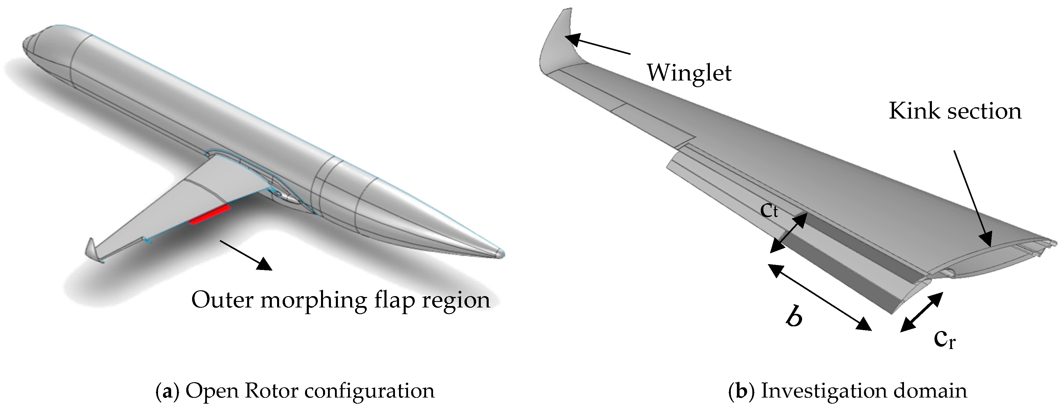
Air transport contribution to climate change represents the 3% of manmade CO2 emissions and 12% of all transport sources with flights producing 628 MTonnes of CO2 yearly. Worldwide, it is estimated that the equivalent of 1300 new international airports will be required by 2050 with a doubling in commercial aircraft fleets. The aviation industry is therefore facing the challenge to meet the predicted growth in demand for air travel increasing (4–5% per annum over the next 20 years) while avoiding detrimental impacts on the environment. The Advisory Council for Aeronautics Research in Europe (ACARE) sets the reduction of environmental impact for aeronautics as one of its main targets, thus requiring new technological solutions for reducing CO2 emissions, by 50% between 2000 and 2020, NOx emissions by 80% and noise by 50%. Moreover, it specified that the aircraft lifecycles should be taken into account in order to reduce the environmental impact of manufacturing, maintenance, and recycling. In 2007, the European Union founded the Clean Sky Joint Undertaking with the main purpose to bring aeronautics research and innovation stakeholders closer together, working on ambitious projects in technologies aimed at reducing, by 2020, the global environmental impact of the aircraft [1]. From this perspective, regional aviation is a key factor for creating resources and an efficient air transport system that respects the environment, ensuring safe and seamless mobility, whilst reinforcing Europe’s aero-industrial leadership. A substantial contribution to Clean Sky derives from Regional Air Transport that, to drastically reduce the environmental impact, adopts innovative solutions across several technology domains. Clean Sky was divided into different subprograms, one of them specifically directed to adaptive architectures, [2]. Advanced architectures have been already or will be developed to be adaptive as wing control surfaces for loads control function and/or innovative high-lift devices (smart droop nose, morphing flap) in order to achieve lighter and simplified actuation/kinematic systems including relevant electronic control. Morphing structures have been investigated within a large number of research activities over recent decades. Morphing wings matching the optimal aerodynamic shape at any flight condition is the most challenging aeronautical application. Current projects will provide technology maturation (TRL, Technology Readiness Level 4/5) for the structural-mechanics and materials aspects, including full-scale limited experimental validations. The adoption of morphing control surfaces and their validation in an operational environment through fly testing therefore represent a step forward, looking at potential application of such technology to innovative green airliners. More in detail, the change in shape of the metal wing structures has always attracted the scientific community. In this regard, based on specific application needs, multiple unconventional architectures have been idealized and built up. A first remarkable distinction within the adaptive systems can be made according to two macro-groups of interest: mechanized and compliant architectures. The first one implements morphing through rigid roto-translation of linkages interconnected by kinematic chains, [3,4,5,6,7,8,9,10,11,12,13,14,15,16,17,18]. The sizing is led so that each kinematic sub-component withstands the external stresses foreseen in the real operating conditions; the actuators and the transmission lines must allow the correct kinematic behavior of the system, ensuring the achievement of target shape-configurations. The available mechanical torques are chosen to balance the aerodynamic loads while minimizing power consumption [5,7,8,19,20,21]. On the other hand, the compliant mechanisms, [22,23,24,25,26,27,28,29,30,31,32,33,34,35,36], reach the required shapes through the deformation of structural elements. In this case, in order to guarantee a more uniform shape change, the mechanical resistance characteristics must be appropriately distributed throughout the system. Compared to compliant mechanisms, ‘robotized’ architectures provide a more practical solution to the paradox of morphing a structure which has to be considerably stiff to safely withstand external loads and—at same time—enough flexibility to accommodate different shapes with a small amount of actuation energy. Fewer actuators are typically required to control the morphing process which expected benefit expected at system level drives the definition of additional mass, volume, force, and power required by the actuation system. In force of this consideration, it naturally follows that the adoption of mechanized structures becomes quite mandatory when dealing with large aircraft applications [3,4,6,8] and/or when multi-modal morphing functionalities have to be assured, [17]. European research projects such as JTI (Joint Technology Initiative)-Clean Sky [2] and GRA-ITD (Green Regional Aircraft—Integrated Technological Demonstration) have been important occasions to demonstrate technological achievements to be integrated into future green open-rotor aircraft (EASA, European Aviation Safety Agency, CS-25 category, [37]). In particular, the authors were involved in research aimed at the design and technological validation of a smart articulated architecture: the key insight was to replace a standard configuration of double slotted flap with a single slotted morphing flap. The main challenge was to enhance aircraft high lift performance—as maximum achievable lift coefficient and stall angle—in addition to the reduction of the noise levels released by the high lift system. The investigations were addressed with reference to the outer portion of the flap segment (b = 3.60 m, cr = 1.20 m, ct = 0.90 m) (Figure 1), [14]. The Regional Aircraft IADP will focus on demonstrating and validating key technologies that will enable a 90-seat class turboprop aircraft to deliver breakthrough economic and environmental performance and superior passenger experience. Regional aircraft are a key element of Clean Sky 2, providing essential building blocks towards an air transport system that respects the environment, ensures safe and seamless mobility, and builds industrial leadership in Europe. The Regional Aircraft IADP (Innovative Aircraft Demonstrator Platform) will bring technologies to a further level of integration and maturity than currently pursued in Clean Sky. The goal is to integrate and validate, at aircraft level, advanced technologies for regional aircraft so as to drastically de-risk their integration into future products. The control of the shape of adaptive devices has the potential to improve the aerodynamic performance of the wings with respect to off-design situations. A possible way to achieve this goal is to implement specific technologies for morphing trailing edge aimed at modifying the airfoil camber in flight. As part of the Clean Sky project, an innovative actuation system has been developed that comprises electro-mechanical modules. A challenging key aspect is the ability to get and preserve desired target wing shapes within a certain tolerance, allowing optimal aerodynamic performance in operative conditions (and loads). In this paper, the strategies followed to define the electro-actuation and control system of a morphing flap are outlined with emphasis on both numerical and experimental methodologies that have been implemented.
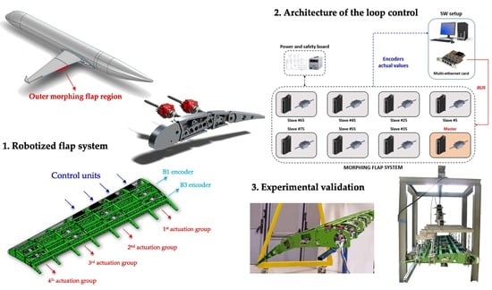
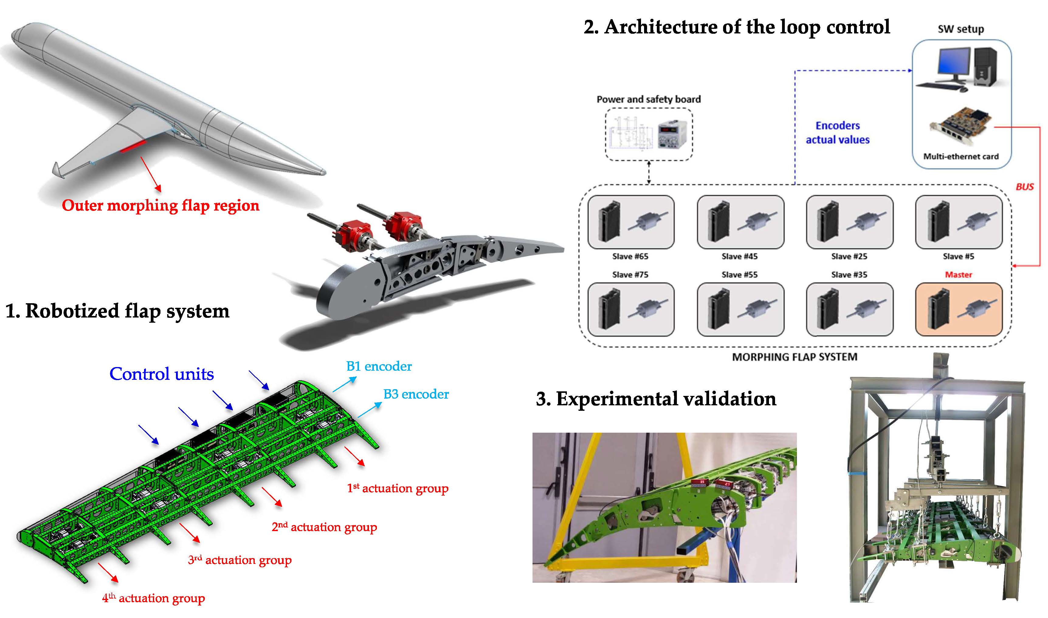
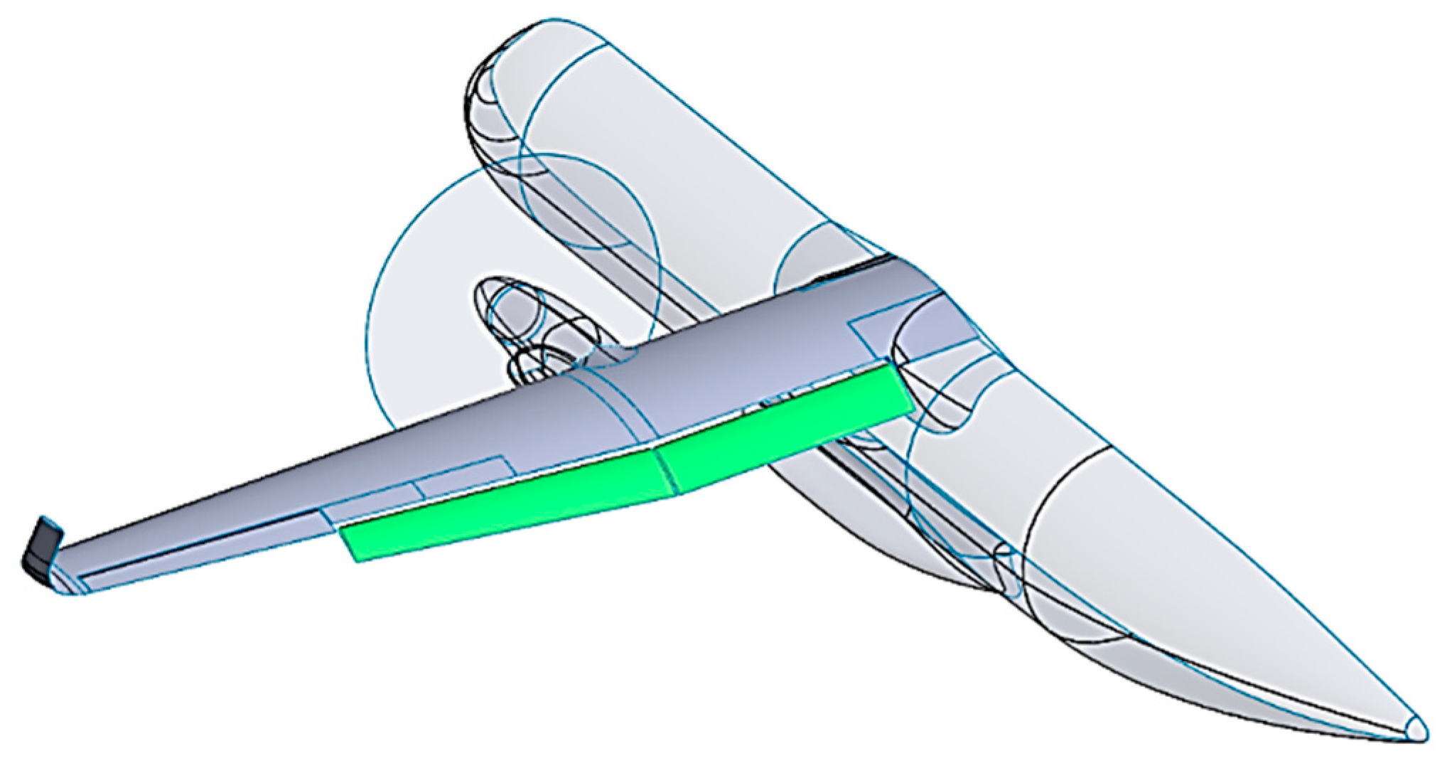
In 2014, the European Commission officially launched Clean Sky 2, the second phase of the most important aeronautics research and innovation program ever undertaken in Europe. The continuation of Clean Sky will allow Europe to develop environmentally friendly, efficient aircraft solutions intended for the worldwide marketplace and meeting society’s expectations. Beyond industrial examples such as cabin technologies, manufacturing, maintenance, hybrid propulsion and others, many major research efforts are being launched or planned in Clean Sky 2. In the framework of the Clean Sky 2—Airgreen 2 project, a novel multi-functional morphing flap technology was investigated to improve the aerodynamic performances of the next Turboprop regional aircraft along its flight path, Figure 2. Within such research scenario, an un-shafted distributed electro-mechanical arrangement represents an attractive solution for the actuation system of the morphing flap, in full agreement with the current needs for a ‘more electrical aircraft’. Despite the progress achieved in smart materials technology, their high power consumption, requiring a heavy power system, has limited their application in aerospace. Consequently, the aviation industry is moving towards well established electro-mechanical actuation solutions for rapid application in flight. Lightweight actuators are part of the trend in green aviation. Maximizing the integration of electrical systems in future aircraft will reduce their weight. The adoption of electrical actuators, such as DC (Direct Current) motors, will bring multiple benefits in addition to those gained by morphing, because such actuators are lightweight, can be easily integrated into a structural system, and need less power than smart materials. The paper deals with the design of the electro-mechanical actuation system for a full-scale flap as an alternative solution to the standard hydraulic actuation based mechanisms. Design activities and experimental validation (ground test) of the proposed arrangements are both covered.
2. Robotized System Architecture
2.1. Mechanical Constraints
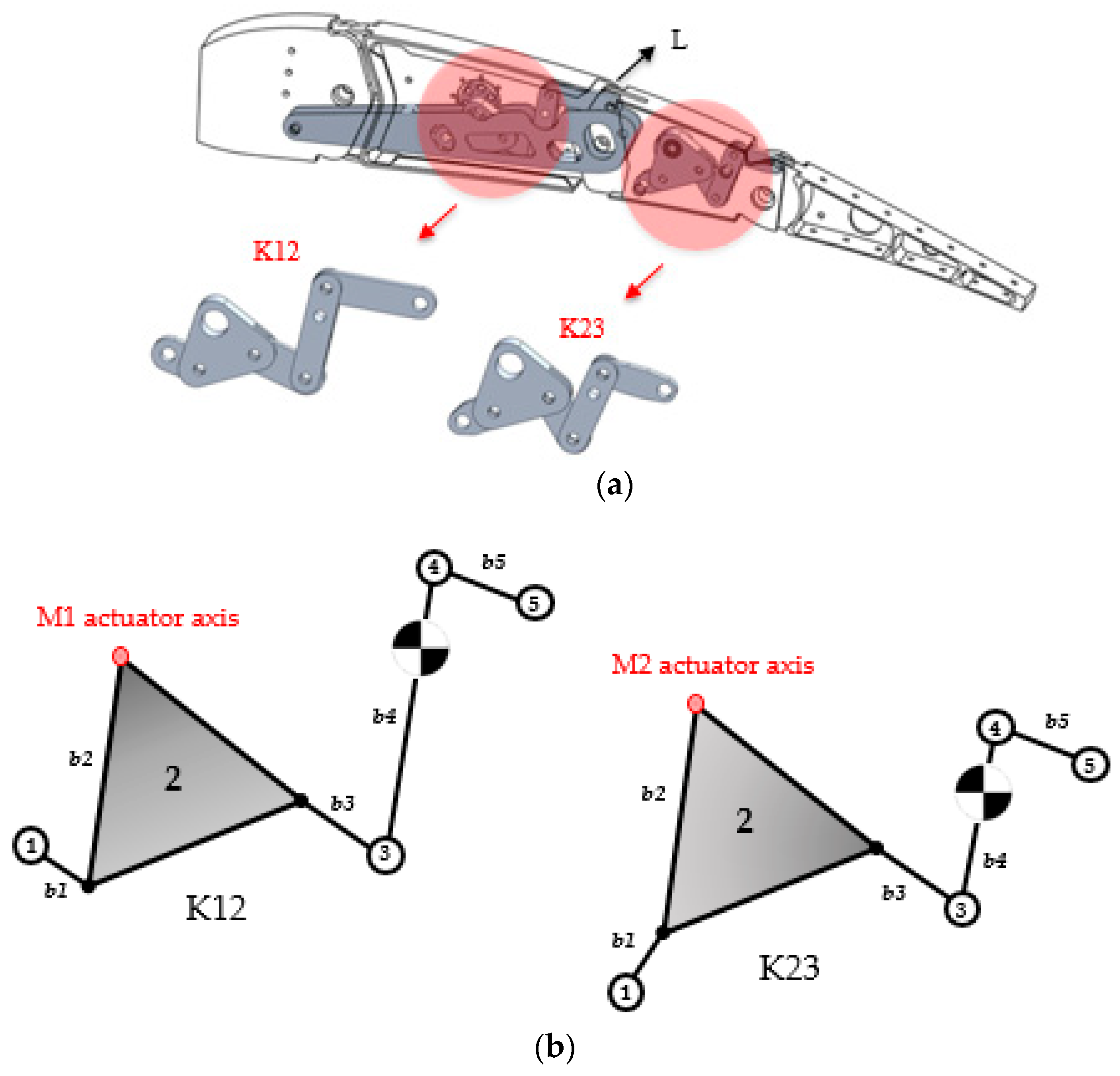
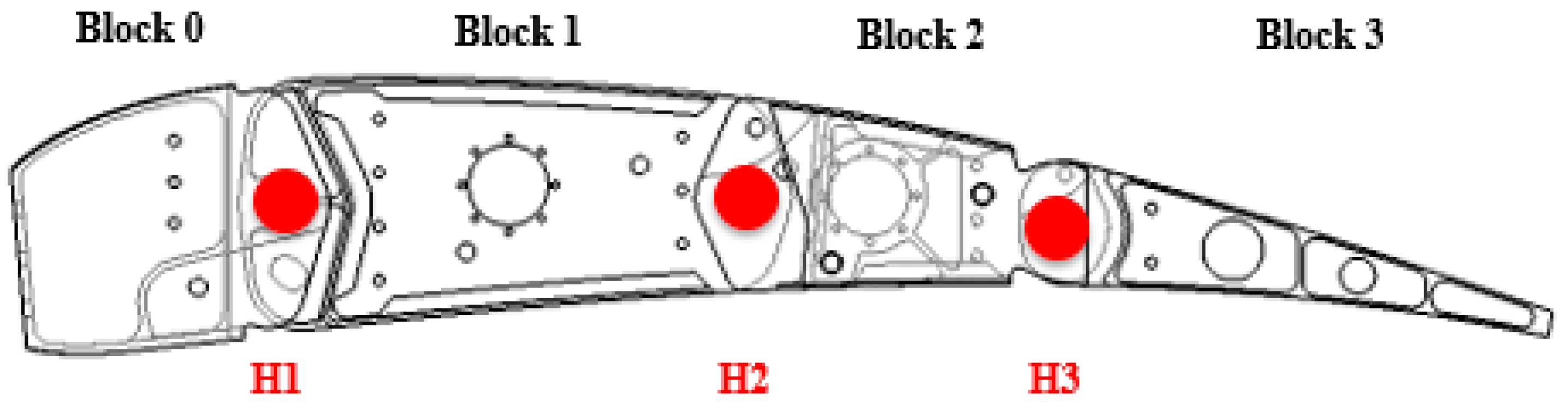
A multi-disciplinary design approach aimed at creating a fully robotic system was followed by the authors. Obviously, the demand for augmented functionality, inevitably leads to more complex design arrangements. In the current application, a rigid links based mechanism has been tailored as a potential solution allowing for the reversible transition from a basic flap shape to a family of possible configurations. More in detail, each of the eight flap ribs was assumed to be articulated; it was segmented into four consecutive blocks (B0, B1, B2, and B3) connected to each other by means of cylindrical hinges displayed on the airfoil camber line (H1, H2, H3) in a ‘finger-like’ configuration. In this way, consecutive blocks can rotate relatively. The conceptual layout of the adaptive rib has been properly adapted to fit the geometry of the flap device in correspondence of eight span-wise sections suitably defined according to well-known structural design criteria. The adaptation included only a slight reshaping of the rib boundary and the extension of the chord-wise length of blocks B0 and B3 while moving from the root to the tip section. The chord-wise length of blocks B1 and B2 has been kept equal for all flap sections thus obtaining hinge lines perpendicular to rib reference planes. In Figure 3, a single-bay assembly is shown. Moreover, non-consecutive rib plates are connected by means of a link (L) that forces the camber line segments to rotate according to specific gear ratios. The ribs kinematic was transferred to the overall flap structure by means of a multi-box arrangement. The implementation of multi-block ribs as internal movable articulation of the flap skeleton allowed for achieving the shape transition, Figure 4. An internal leverage (K12) is hosted by block B1 and links blocks B1 to B2. Such leverage amplifies the torque which comes from the external actuator (M1). The architecture of the rib is designed in such a way that the position of both the connection L and the pivots of the levers allow the motion of all the blocks around the hinges according to the predetermined shapes, as a consequence of the rotations imposed by the actuators. In fact, by analysing the morphing mode, the rotation induced by M1 causes the lever K12 to move and therefore modifies the relative position of block B1 with respect to block B3. The internal linkage therefore allows the rigid transfer of motion to the blocks B0 and B2, mutually interconnected to the others. The rotation of the actuator M2 drives instead another leverage (namely K23) which connects B3 to B2. The second chain K23 makes it possible to amplify the available torque especially when the flap is stowed and the flap tab has to be deflected for cruise load control. The morphing rib arrangement was suitably adjusted to fit the flap-like geometry with respect to each span-wise section: the adaptation included only a slight remodelling of the upper and lower limits and the extension of the chord length of the B0 and B3 blocks as it moved from the internal to the outer section. The chord dimension of the blocks B1 and B2 has been kept the same for all the sections of the flap thus obtaining hinge lines perpendicular to the reference planes of the ribs. Two C-shaped (continuous) spars (supposed to be made of aluminium alloy Al2024-T351) were placed at 5% and 70% of the local wing profile chord to connect all blocks B0 and B3 along the span.
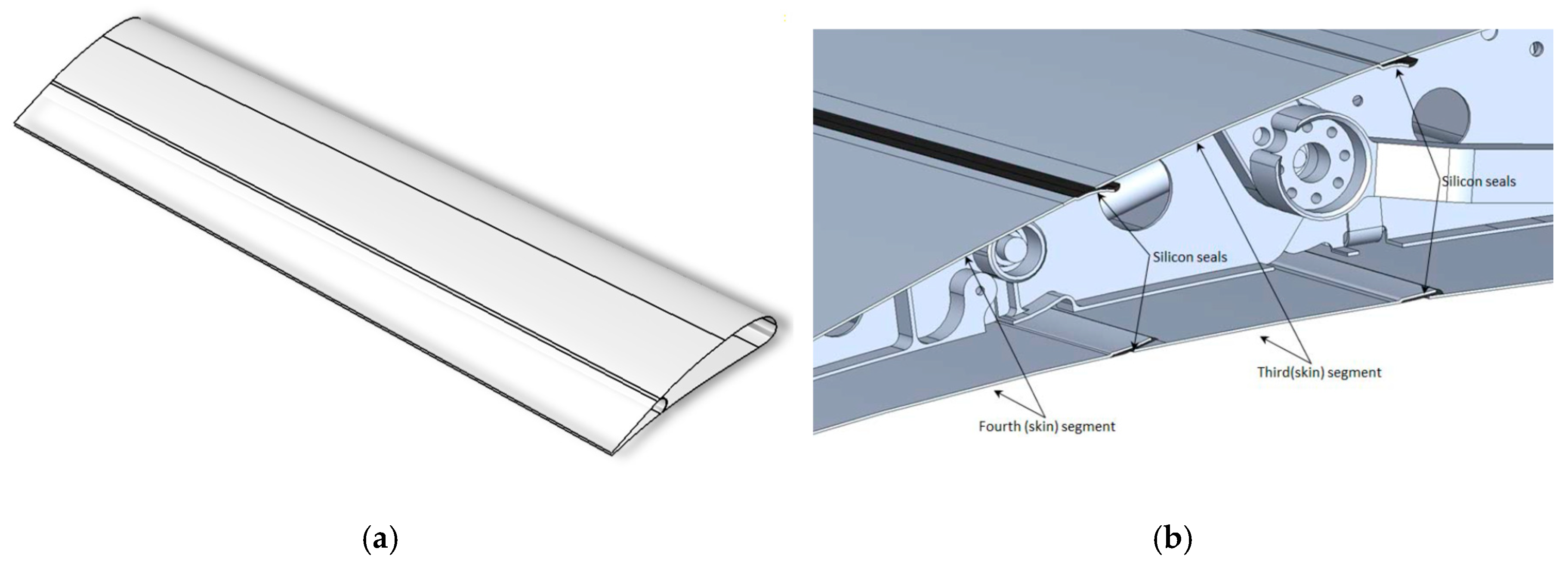
The spars have been appropriately designed to provide the maximum stiffness contribution in absorbing external loads while ensuring adequate deformation levels for the whole device. A multi-box configuration comprising both transversal spars and longitudinal stringers (in Al2024-T351) has been conceived to be elastically stable under bending and twisting. Both the ribs and the longitudinal stiffening components have been suitably shaped to allow the installation of a segmented skin solution characterized by four shells in Al2024-T4 which slide on each other during morphing (armadillo-like skin). Rubber seals were used to prevent friction between adjacent skin segments and to prevent airflow losses. The outline of the seals has been defined according to the actual kinematic evolution of the complete flap. These considerations also allowed for the verification of the assembly tolerances implemented while demonstrating the absence of interpenetration between adjacent secondary components in relative motion. The final arrangement of the device is shown in Figure 5 while the skin segments in Figure 6. Silicon seals (chemically stable in the range of temperature (−50 °C; +80 °C) were glued along the contact region between consecutive skin segments, thus preventing airflow penetration inside the structure.
2.2. Actuation Design
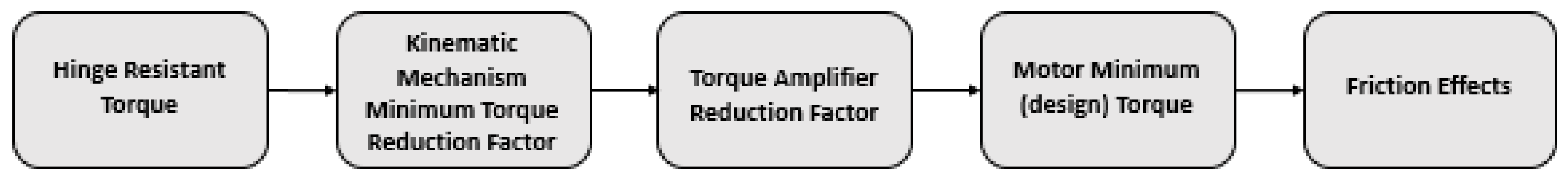
On the basis of preliminary addressed analysis, several load conditions were considered to size the distributed actuation system of the morphing device. After evaluating the most severe aerodynamic hinge moment, the torque to be provided by the actuation system was derived: direct current (DC) actuators were located in correspondence of three bays thus assuring a more controllable morphing shape along both the span-wise and chord-wise direction. The attainment of the required torque is ensured by speed reducers (Harmonic Drive, HD®, https://harmonicdrive.de), keyed on the motor shafts; HD® represents a typical gear widely used in mechatronic applications. Among its main advantages: no backlash, compactness and light weight, high gear ratios (in such application 120:1), reconfigurable ratios within a standard housing, good resolution, and excellent repeatability when repositioning inertial loads and high torque capability. The key aspects of the design method implemented for the actuation system are reported in Figure 7.
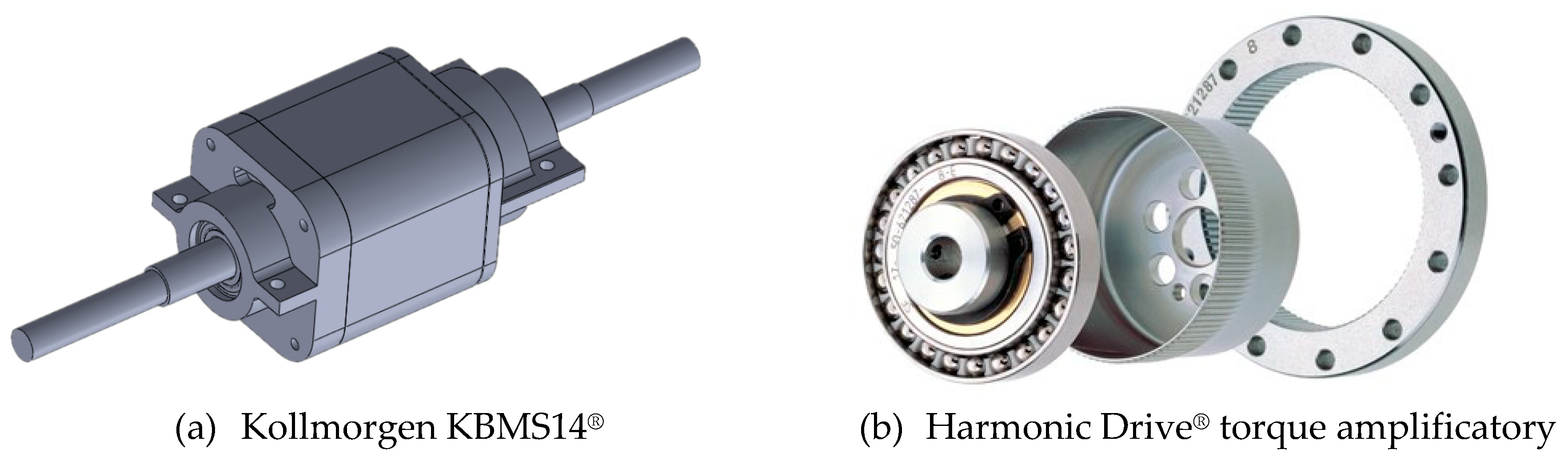
Sensitivity studies were carried out to find out the minimum number of actuators required to morph the flap under the action of design aerodynamic loads. Relying upon the available space and taking in account specific constraints in terms of efficiency, power, and reliability, the Kollmorgen® (https://www.kollmorgen.com) brushless motor KBMS-14 was selected (Table 1). The actuation solution—arranged in four groups—has been considered satisfactory to move the structure under the action of aerodynamic loads. They were respectively linked to the 1st, 3rd, 5th and 7th bay and duly coupled to Harmonic Drive® gearboxes (model HFUC–17–120–2UH–SP2983, Table 2), hosted by ribs blocks and acting as amplifiers of the actuation torque (and reducers of the shaft rotation speed). In Figure 8 the actuator and gearbox models are roughly depicted.
Such actuation system allowed each rib mechanism to produce a total output torque (TOUT) equal to
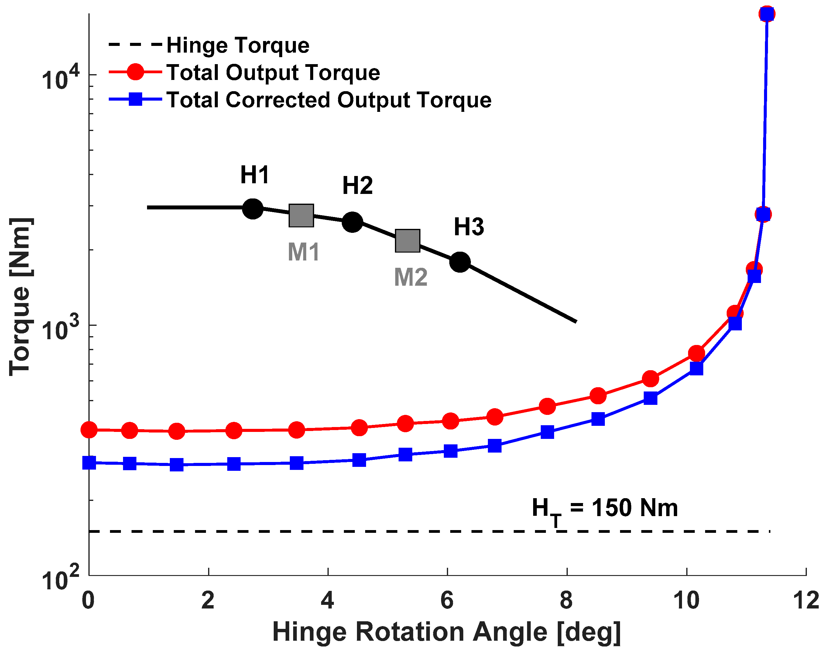
where MT is the motor torque assumed constant and equal to half of the stall torque (0.6 Nm) in correspondence with the operational speed (ω = 400 rpm); RHD = 120 is the Harmonic Drive® constant torque amplification factor; KMA is the kinematic mechanical advantage, assumed to be equal to the minimum torque amplification factor of about 5; CfHD represents a torque correction factor that was conservatively assumed equal to 0.75. Actuation total output torque (1) (with and without the CfHD correction factor) and H3 hinge torque trends are reported in Figure 9 (logarithmic scale) as function of the H3 hinge rotation angle. From Figure 9, it is evident that the actuation system is capable of overcoming the resistant hinge torque with high margins. In Figure 10, the assembly sequence of the actuators, gearbox, and rib blocks is roughly depicted.
TOUT = MT·RHD·KMA·CfHD
3. Morphing Flap Overview
Target Shapes and Specifications
The articulated mechanism for flap camber morphing was designed with reference to the most severe load condition expected in service; from an accurate comparison of the solicitations induced by more than 20 different load cases, the enveloping limit condition was found as the climb case related to uncambered flap deployed at 35°, δflap = 35°, flight speed V∞ = 95.2 m/s, angle of attack α = 6°, sea level and max zero fuel weight. The highest resisting hinge torque (HT = 150 Nm) occurred in correspondence of the hinge axis connecting blocks B2 and B3, indicated with H3 in Figure 11 [17]. This led to the choice of such resistant hinge torque as the designing one for all the actuation kinematic mechanism. However, in order to deal with a high entity design torque, it was mandatory to introduce some suitable torque amplifiers devices into the actuation system.
A first phase of the work involved the determination of optimized airfoil shapes at a several flight conditions. The scenario of the project was very broad and involved both academic and industrial partners. The aerodynamic requirements were in fact defined by Leonardo Finmeccanica—Aircraft Division. 2D CFD optimization simulations were addressed to assess the design morphed shapes, as outlined in [33]. These results were used as input data to design a structural concept that guaranteed the reversible transition of the flap from the nominal configuration (baseline) to the target shapes. These optimized shapes were used as a starting point for the actuation system design; in correspondence of these shapes the aerodynamic loads to be counteracted by the actuation kinematics were evaluated together with the strain/stress field induced all over the structure. Table 3 recaps the rotations angles of flap rib blocks useful to reproduce the flap target shapes.
4. Control Logic Strategy and Lab Test on Iron Bird
4.1. System Arrangement
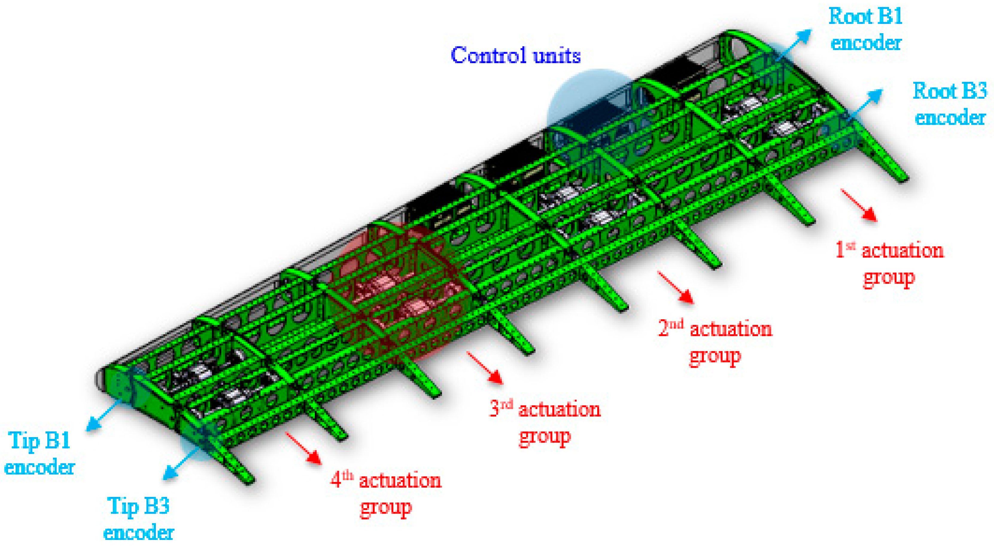
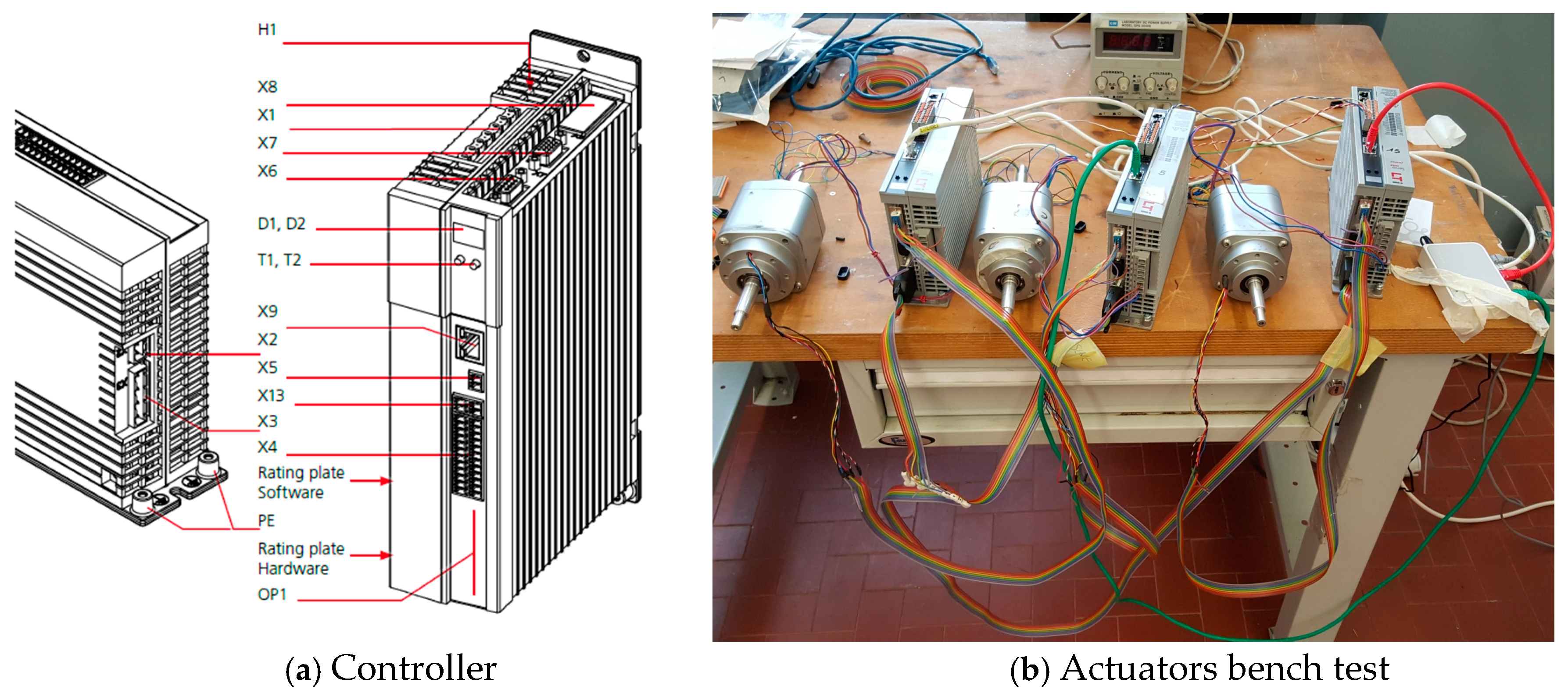
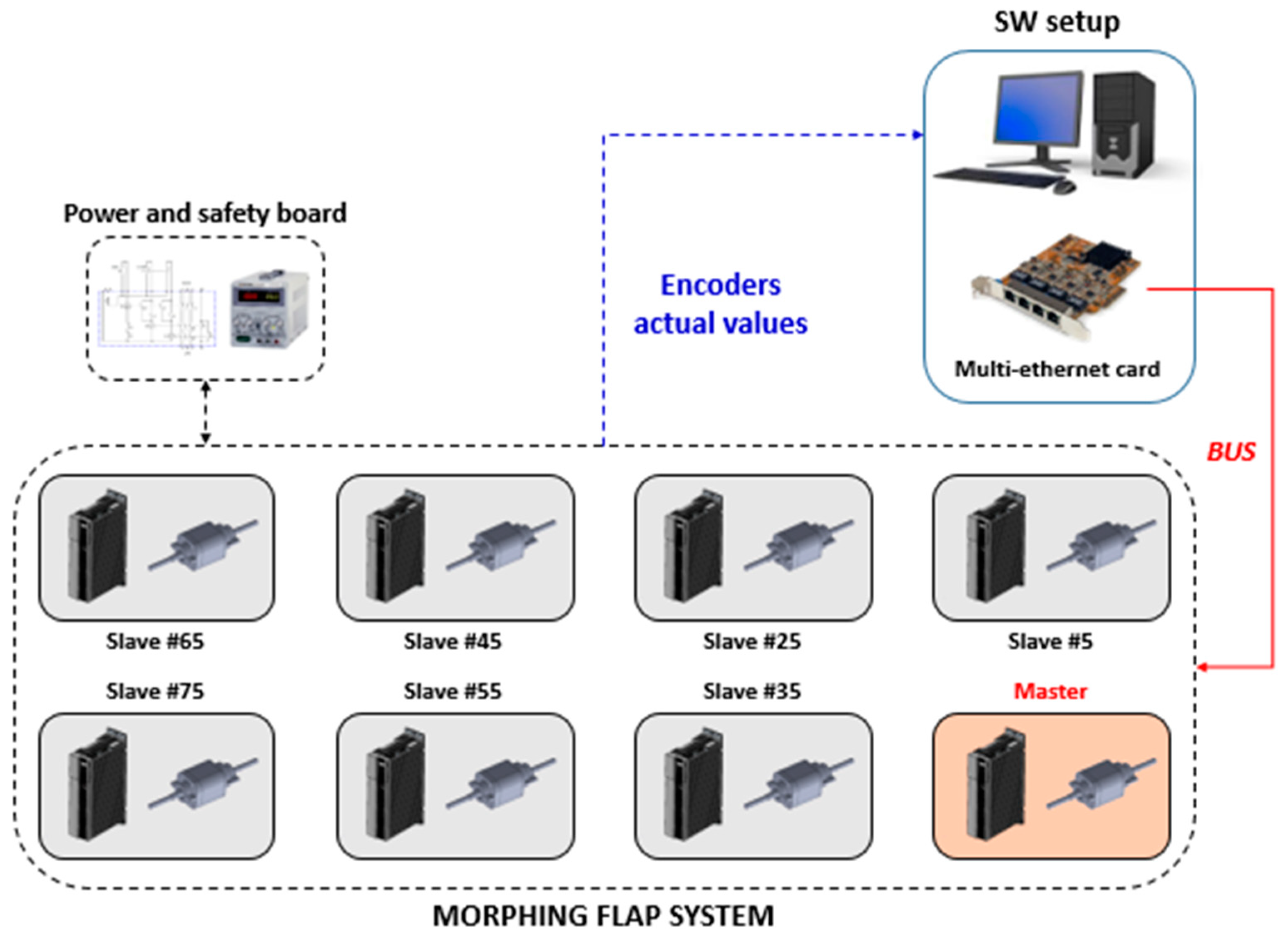
The transmission chain along the chord-wise direction consisted basically of a kinematic mechanism, driven by load-bearing brushless actuators that acted directly on morphing ribs. The absence of a transmission shaft along the span, and the distributed arrangement of electromechanical actuators (EMAs) derived from the very demanding size and weight constraints the system has to comply with. Moreover, a distributed sensor system based on relative encoder generated the signals for the appropriate feedback actions and, at the same time, monitored possible faults inside the actuation mechanism. Eight controllers (ServoOne Jr. by LTI® motion, https://www.lti-motion.com, Figure 12a, [14,15]) were mounted in the first four bays of the leading edge in order to drive the actuation groups. Encoders for relative rotation measurement were placed at the hinges H1, H2, and H3 of the ribs at stations 1, 4, and 8. The measured rotations were then used to rationally drive the actuators and to preserve the commanded flap shape in case of variation induced by external perturbations (including aero-loads). The electric connection among all control units, was realized by means of a proper shielded routing, guaranteeing the logic correspondence between servo-drivers plugs and terminal pins. Such connection arrangement enabled the synchronized trigger of the actuators according to the master-and-slave-based logic depicted in Figure 12b.
The transmission ratios imposed between the slave and master EMAs were set as 1:8 and to 1:1 respectively for the first row (Block 1) and for the second row of actuators (Block 2) in chord-wise direction. A value of speed equal to 400 rpm was set for all the actuators and an acceleration/deceleration of 100 rpm/s was implemented to obtain a quasi-static morphing evolution (15 s duration) without dynamic oscillations due to inertial effects. As shown in Figure 13, the control loop of the actuator position used the motor encoder position as feedback signal. The bench test provided a first experimental validation of the designed controller and its hardware integration architecture; moreover, it was possible to appreciate the reproducibility of the theoretical reference and optimized airfoil shapes. On the other hand, the test offered the opportunity to make some adjustments in the mechanical part of the model and some tunings of the encoder transducers zero positions. When the controller was tested on the bench two steps were performed:
(1) Stand-alone verification of each actuator;
(2) Simultaneous testing of the actuators controlled by the central servo-drive, Figure 13.
This logical scheme enabled the synchronized activation of actuators according to the master and slave multi-axis strategy.
The morphing flap prototype was used as mechanical demonstrator to prove the adequacy of the adopted solutions with respect to design requirements and system specifications. Three test campaigns were carried out:
- functionality test campaign;
- tatic test campaign;
- ground resonance test.
The main objectives of each campaign have been outlined in the following subparagraphs together with a general description of performed pre-test activities and test outcomes. In order to visually check the status of the inner structure and embedded equipment, skin modules were removed during all tests. For static tests, the applied load was reduced in order to compensate for the increased structural elasticity due to the absence of the skin.
4.2. Functionality Test
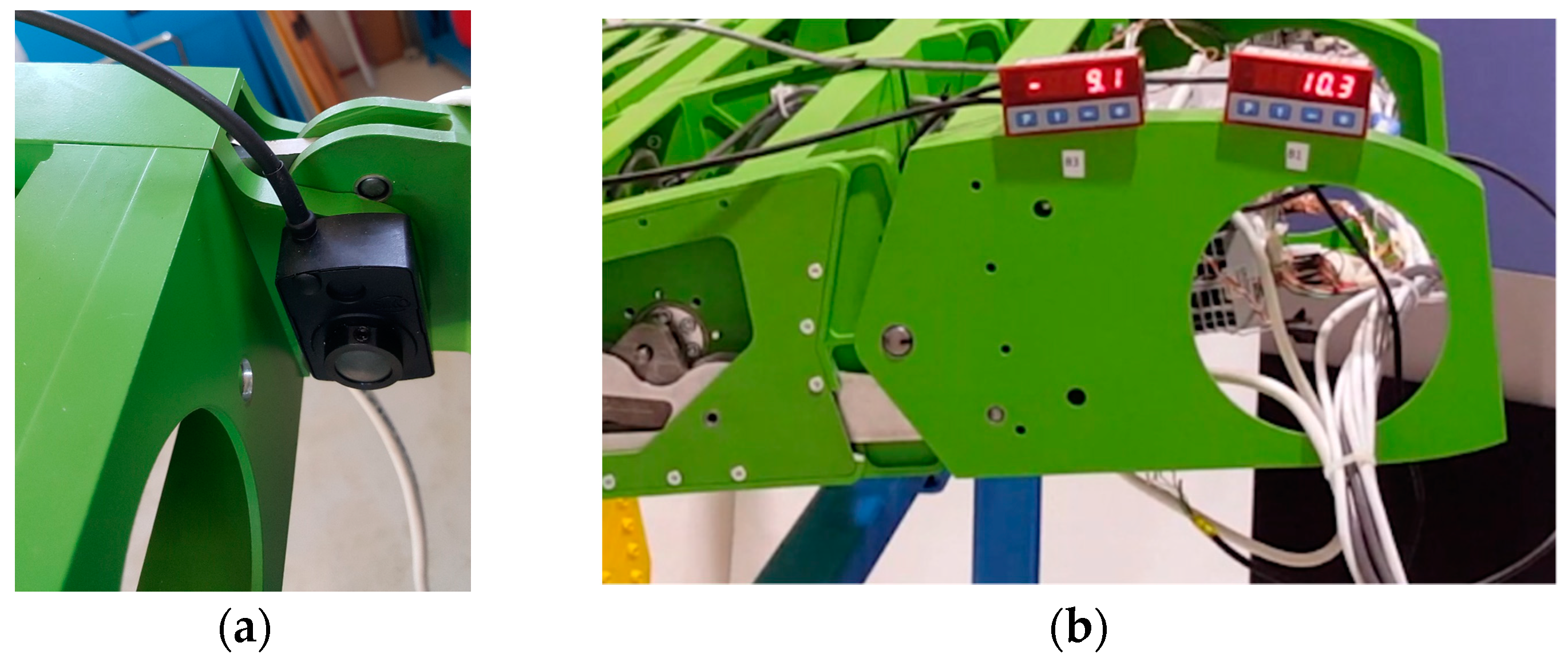
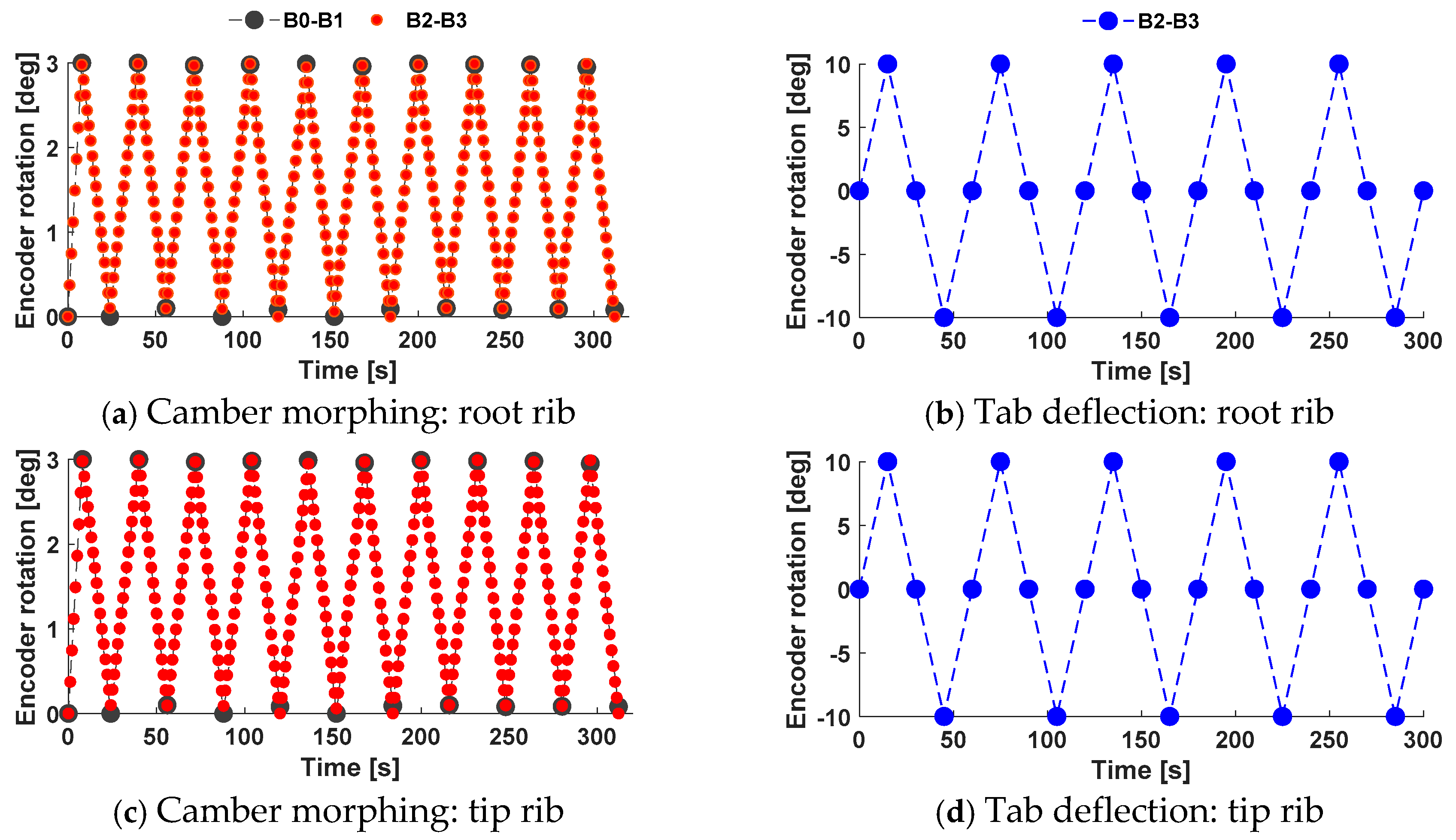
These tests were carried out to demonstrate that the device was able to reproduce target morphed shapes in a controlled and repeatable manner (Figure 14). The target morphed shapes were considered successfully achieved if the angles between adjacent rib blocks—obtained upon actuators activation—matched the design values pertinent to each morphing mode (Table 4) with a precision of 0.5°. According to the general layout presented in Figure 5, the first and the last sections of the flap were then equipped with additional high precision encoders measuring—in LabVIEW® environment—the relative rotations between blocks B0 and B1 and between blocks B2 and B3 (Figure 15); due to the mechanical link between B0 and B2 it was considered un-relevant to place an additional encoder also between B2 and B3. Additional encoders were equipped with digital displays for real-time measure reading. Test protocols (Table 4) were repeated 20 times and at each cycle the measured angles resulted fully compliant with the design expectations at both inner and outer flap sections, Figure 16.
4.3. Static Test with Powered Actuators
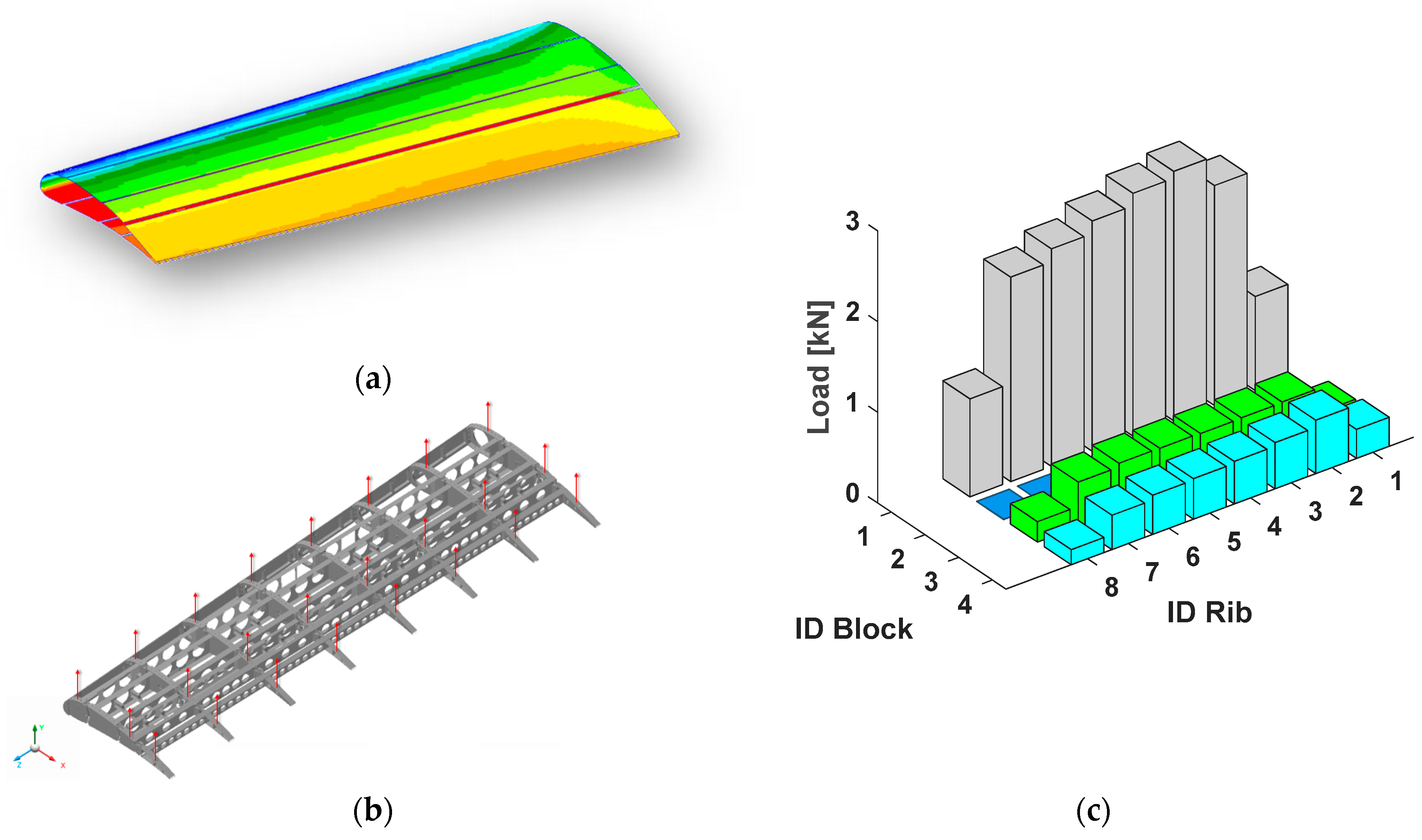
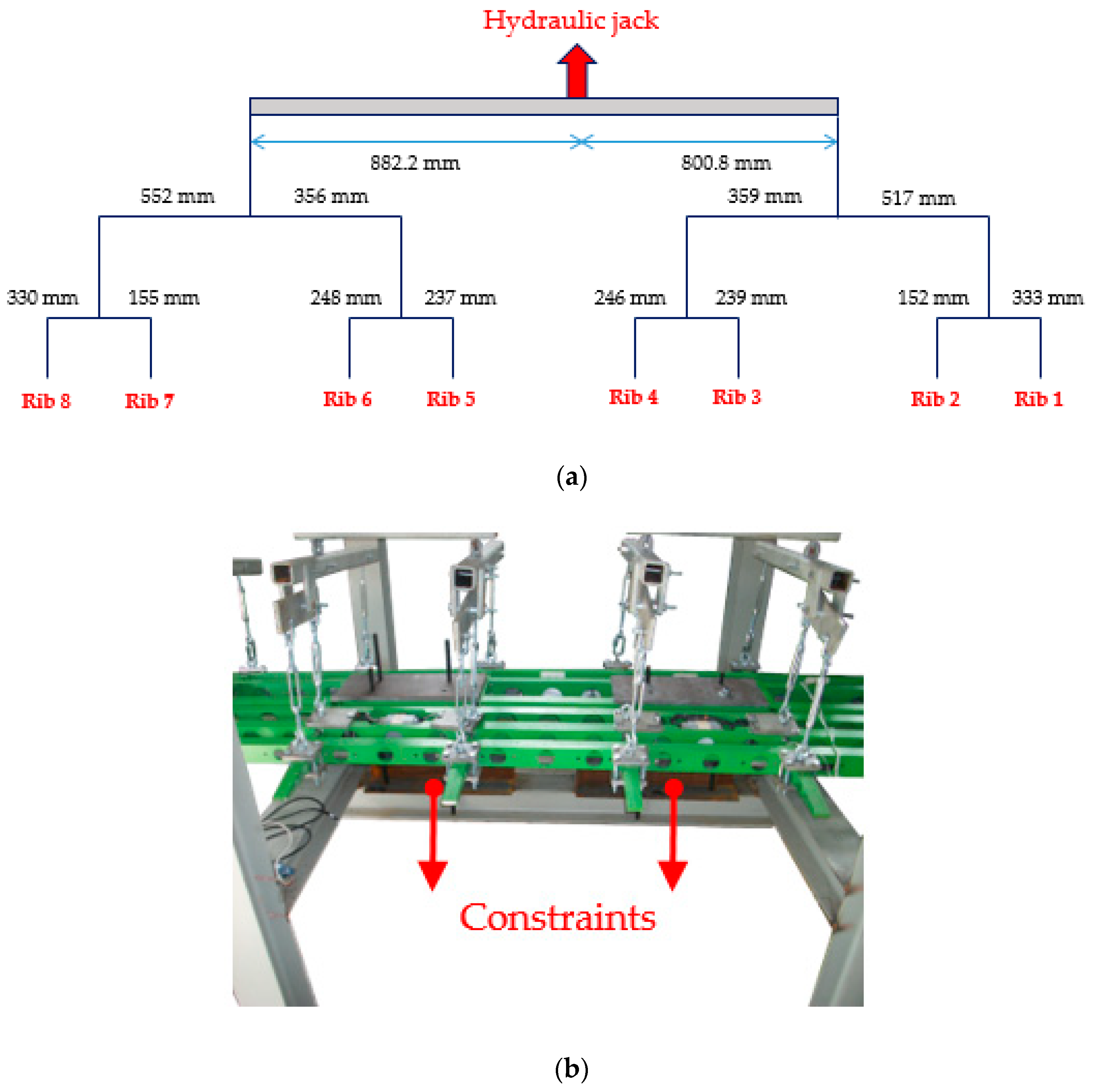
Static test was carried out to demonstrate the flap’s capability to withstand limit loads without permanent deformations, failures or buckling (as per part C of EASA airworthiness requirements CS-25, [37]). The flap was constrained in correspondence of the blocks B1 belonging to the third and the sixth rib (from the root section) thus simulating a joint with a potential (and ideally rigid) deployment track. The pressure distribution related to the limit load condition (uncambered flap deployed at 35°, δflap = 35°, flight speed V∞ = 95.2 m/s, angle of attack α = 6°, sea level and max zero fuel weight, see Section 2.1) was converted into an equivalent set of lumped forces acting at the centre of rib blocks B0, B2, B3. (Figure 17) and easily reproducible during tests through a whiffle-tree (Figure 18). The maximum vertical force to be applied at the top of the whiffle tree to reproduce the limit design condition (1650 Kg) was reduced by the 10% in order to account for the absence of the skin during test (The skin was not installed in order to allow for a quick inspection of the inner flap structure during the test. The 10% reduction of the maximum load was evaluated on the base of pre-test simulations showing that the induced displacement field along the unskinned flap would have been the same of that induced by the full limit load along the skinned flap). Fifteen load steps of 100 Kg each, with a loading speed of 10 Kg/s, were considered adequate to avoid any dynamic amplification.
A pause of 10 s at the achievement of each load step was moreover set to check data acquisition; load levels were measured through a load cell installed between the hydraulic jack and the whiffle-tree. All the actuators were turned on (powered) during the test in order to provide adequate (electrical) torque to counteract applied loads.
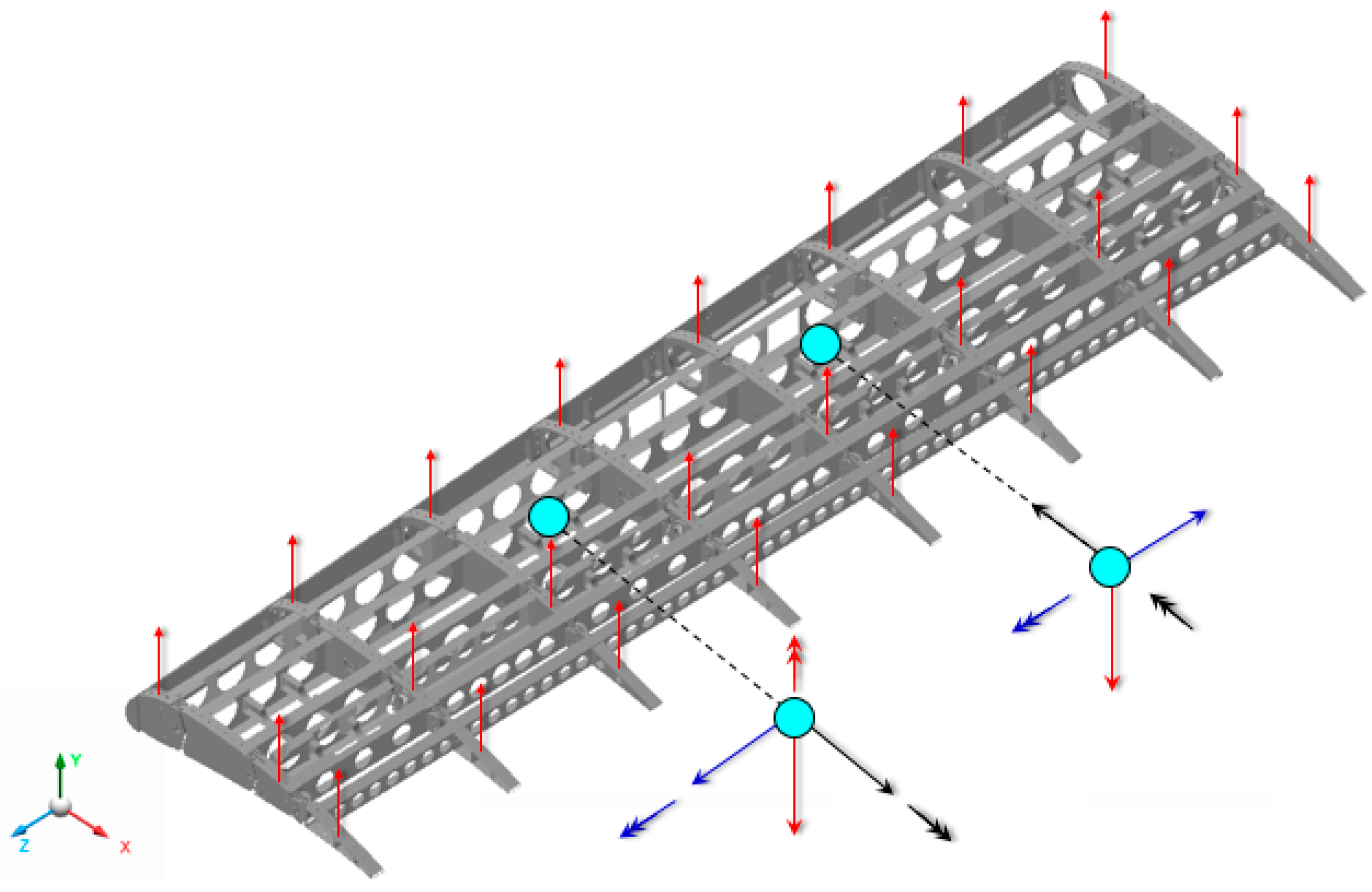
The schematization of the whiffle-tree and the details of the constraints implemented during the test are shown in the Figure 19. A Free-Body Diagram (FBD) is represented in Figure 20, clearly showing where the lumped forces and how the test rig is reacting the load (flap fully clamped in correspondence of blocks B1 belonging to bay 3 and bay 5). Each component of constraint forces and moments are highlighted according to the main reference frame.
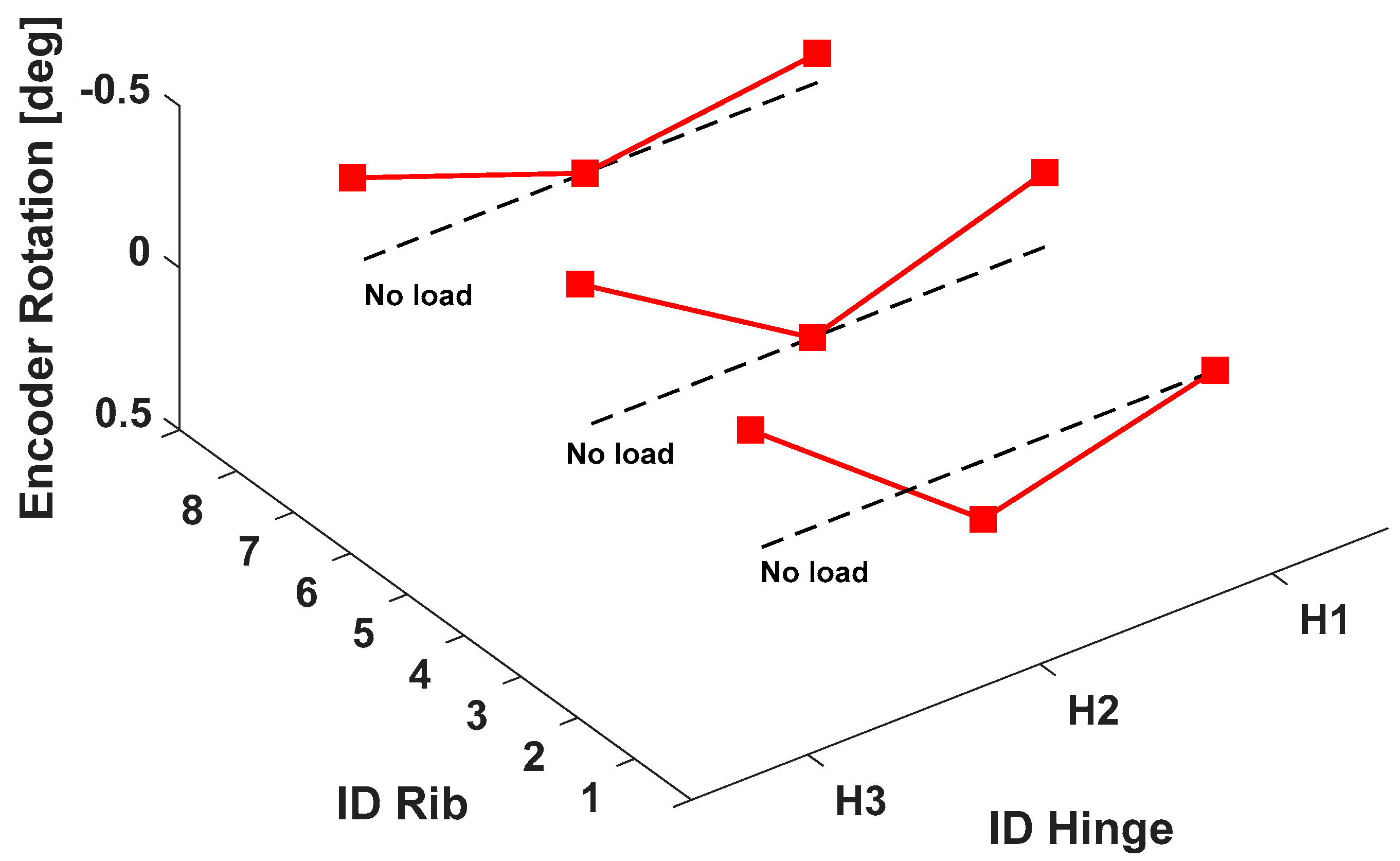
Actuation system capability to preserve the baseline flap shape under the action of aerodynamic loads was positively verified with a maximum deviation that resulted lower of 0.5° (Figure 21). No jamming of the actuation system occurred during the static test; after load removal, the flap was repeatedly morphed, thus proving the full functionality of the actuation lines.
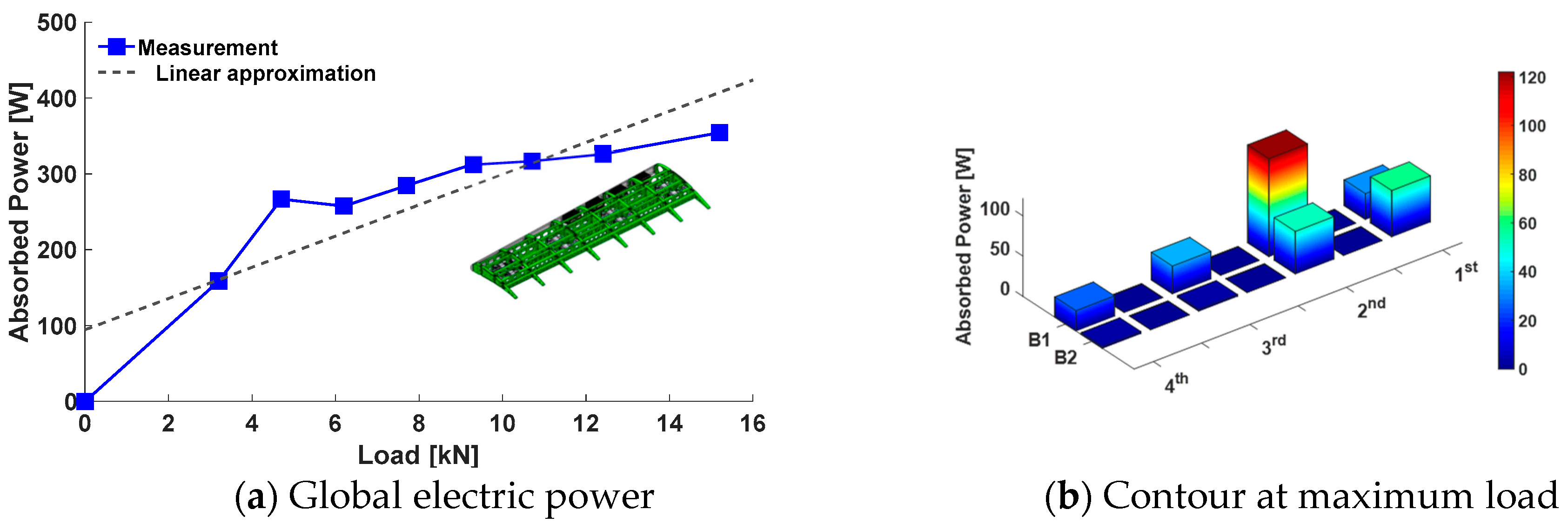
The levels of electrical power absorbed by the actuators during the static test resulted within the nominal target values, thus ensuring the compliance of the system with safety-related aspects related to power supply (Figure 22a). As expected, the obtained power absorption distribution (Figure 22b) recalls the trend of the applied load outlined in Figure 17c. The absorbed power (PABS) was estimated by Equation (2),
where VDC represents the DC link voltage (220 V) and Irms the actual current (Arms). The results show that the current levels absorbed by the actuators are well below the saturation limits indicated in Table 1, thus proving the robustness of the electrical system with respect to possible jamming events at the contingent load condition.
PABS = VDC·Irms
4.4. Dynamic Test
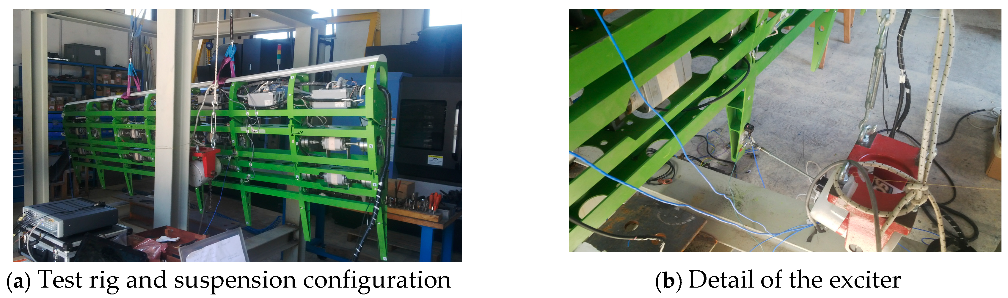
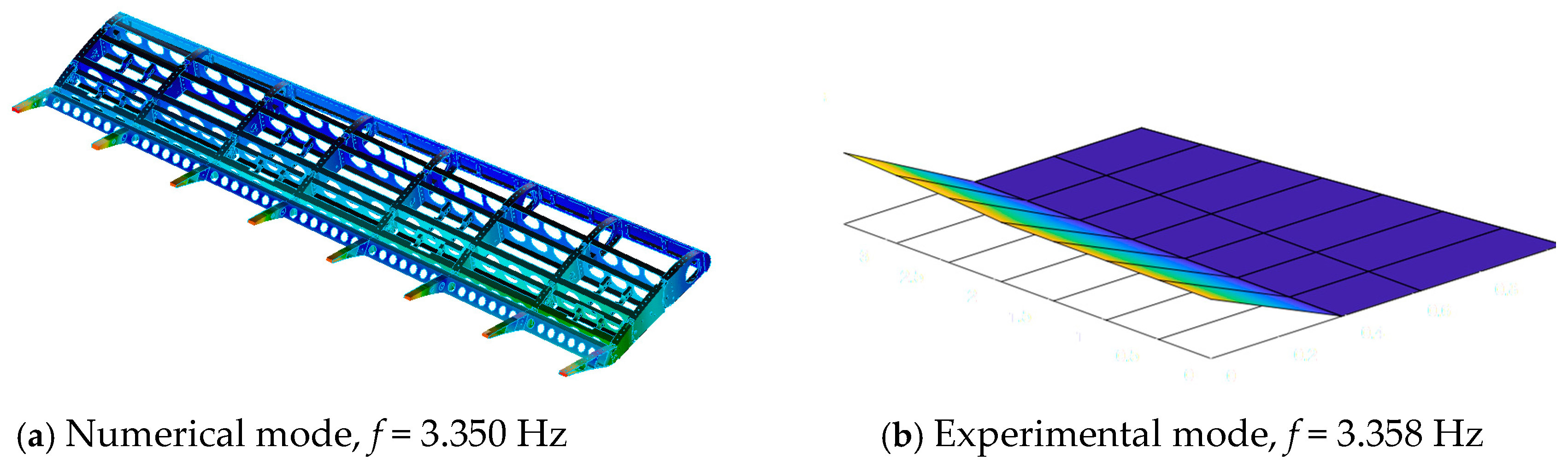
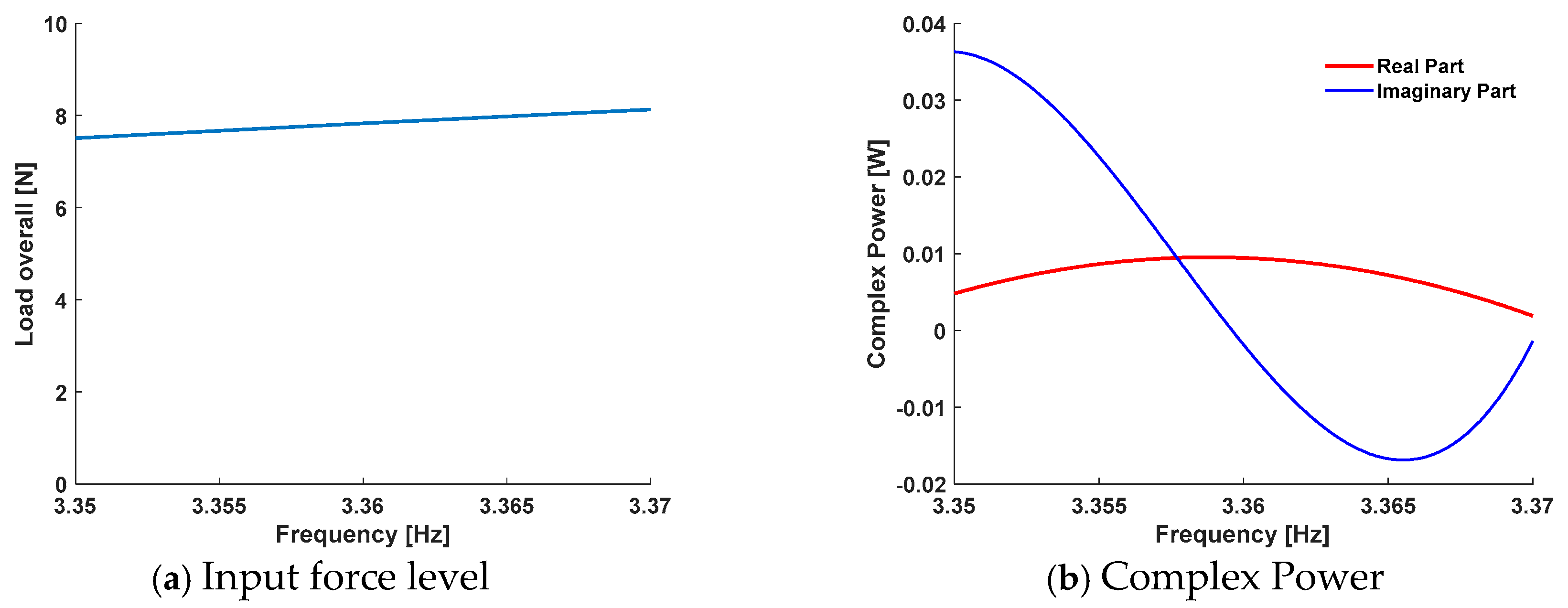
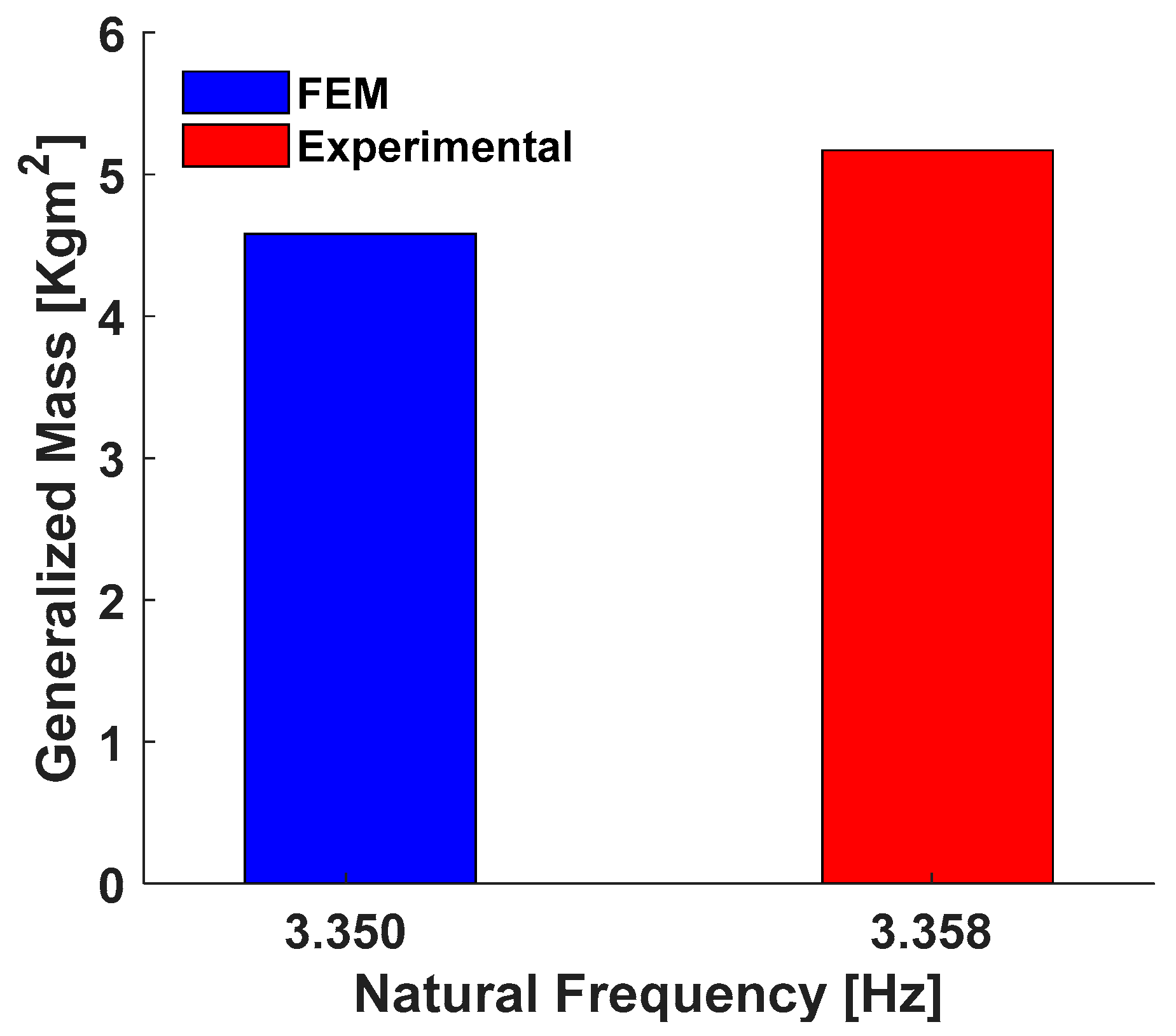
At high speed, only the first three segments of the morphing flap are stowed in the wing while the tab remains exposed to the aerodynamic flow and used for load control. From the aeroelastic standpoint, the tab behaves as a large aileron and detrimental flutter instability may arise from the coupling of the first wing bending mode with the tab harmonic (elastic oscillation of the tab around its hinge axis). Aeroelastic analyses based on numerical models [38,39] proved however that the flap tab design was safe from the flutter stand point considering also the functioning of the electric line feeding the actuators; in order to give experimental evidence of this result, ground resonance tests were carried out to validate the flap dynamic model used for theoretical flutter analyses. This validation was performed by correlating numerical and experimental generalized parameters related to the only flap mode proved to be relevant for flutter stability [39]: the tab harmonic at powered actuators. The flap was suspended to a test rig through soft springs in order to reproduce a free-free condition, Figure 23; all the actuators were shut down. The ‘Normal Mode’ method was then used to detect the generalized parameters of the flap tab harmonic mode in correspondence of powered actuators. The procedure for acquiring modal parameters is generally long and expensive: it requires advanced load control systems and a dense sensing network. In such context, a hand-controlled force was applied, isolating and acquiring the dynamic response of tab modes with only few accelerometers. The experimentally identified tab harmonic (3.358 Hz) resulted well in line with the theoretical expectations (3.350 Hz, see Figure 24). No further modes were detected in the frequency range (0–100 Hz) considered to be of practical relevance for aeroelastic stability phenomena. The generalized mass of the mode was calculated by applying the complex power method, [40]. The control of force level is crucial during this phase, Figure 25a. An active (imaginary and proportional to viscous damping) and a reactive (real and proportional to mass and stiffness) powers components are applied to the system by means of the shakers in the frequency range very close to the measured mode, Figure 25b. With the aim to guarantee that the forces are constant in the considered range of frequency, the measurements are carried out in closed loop. The comparison between numerical and experimental values of tab harmonic generalized mass is summarized in Figure 26; also in this case a very good correlation level was obtained.
5. Conclusions
In the framework of the Clean Sky-JTI project, authors investigated a high TRL solution for an innovative flap element tailored for regional transportation aircraft end application. The conceived device was designed in order to enable two different shape morphing modes depending on aircraft flight condition and flap setting. Geometrical dimensions and design loads related to a true-scale flap segment of 3.6 m span were considered for the definition and validation of the morphing flap actuation system.
A full scale prototype was finally manufactured and tested to:
- demonstrate the morphing capability of the conceived structural layout;
- demonstrate the capability of the actuation system to withstand static loads representative of the limit aerodynamic pressures expected in service.
Rational approaches were implemented in an efficient test campaign providing the necessary database for the mechanical demonstration of the morphing structure. Test outcomes showed that reliable, controllable, and stable morphing compliant with design requirements is assured by the device for both morphing modes. The encouraging outcomes have led to the design of a new architecture of morphing flap. Relying upon the already assessed concept, an innovative and more advanced flap device is going to be designed in order to enable up to three different morphing modes on the basis of the A/C flight condition/flap setting. The third operative mode consists in twisting the flap tab segment (±5° along the outer flap span): it is supposed to be activated in cruise condition only when the flap is stowed in the wing. This additional mode will enable new load control functionalities to enhance wing aerodynamic efficiency.
Author Contributions
Conceptualization: M.A., R.P. and F.A.; Methodology: M.A. and R.P.; Software: M.A. and F.A.; Validation: M.A. and F.A.; Formal analysis: F.A. and S.A.; Investigation: M.A., F.A., R.P. and S.A.; Resources: F.A. and R.P.; Data curation: M.A.; Writing—original draft preparation: M.A.; Writing—review and editing: R.P.; Visualization: F.A. and S.A.; Supervision: R.P.; Project administration: R.P.; Funding acquisition: R.P.
Funding
Part of the research described in this paper has been carried out in the framework of AIRGREEN2 Project, which gratefully received funding from the Clean Sky 2 Joint Undertaking, under the European’s Union Horizon 2020 research and innovation Programme, Grant Agreement No. 807089—REG GAM 2018—H2020-IBA-CS2-GAMS-2017.
Acknowledgments
The authors would like to thank Leonardo Aircraft, for having provided the industrial guidelines and the necessary support to the research work addressed by this paper.
Conflicts of Interest
The authors declare no conflict of interest.
References
- ACARE Official Site. Available online: http://www.acare4europe.com/ (accessed on 17 December 2018).
- Official Site of Clean Sky Consortium. Available online: http://www.cleansky.eu/ (accessed on 17 December 2018).
- Pecora, R.; Amoroso, F.; Magnifico, M.; Dimino, I.; Concilio, A. KRISTINA: Kinematic rib-based structural system for innovative adaptive trailing edge. Proc. SPIE 2016, 9801. [Google Scholar] [CrossRef]
- Pecora, R.; Concilio, A.; Dimino, I.; Amoroso, F.; Ciminello, M. Structural Design of an Adaptive Wing Trailing Edge for Enhanced Cruise Performance. In Proceedings of the 24th AIAA/AHS Adaptive Structures Conference, San Diego, CA, USA, 4–8 January 2016. [Google Scholar]
- Dimino, I.; Diodati, G.; Concilio, A.; Volovick, A.; Zivan, L. Distributed Electromechanical Actuation System Design for a Morphing Trailing Edge Wing. Proc. SPIE 2016, 9801, 980108. [Google Scholar] [CrossRef]
- Wildschek, A.; Grünewald, M.; Maier, R.; Steigenberger, J.; Judas, M.; Deligiannidis, N.; Aversa, N. Multi-Functional Morphing Trailing Edge Device for Control of All-Composite, All-Electric Flying Wing Aircraft. In Proceedings of the 26th Congress of International Council of the Aeronautical Sciences (ICAS), Anchorage, AK, USA, 14–19 September 2008. [Google Scholar]
- Amendola, G.; Magnifico, M.; Pecora, R.; Dimino, I. Distributed Actuation Concepts for a Morphing Aileron device. Aeronaut. J. 2016, 120, 1365–1385. [Google Scholar] [CrossRef]
- Dimino, I.; Concilio, A.; Pecora, R. Safety and Reliability Aspects of an Adaptive Trailing Edge Device (ATED). In Proceedings of the 24th AIAA/AHS Adaptive Structures Conference, San Diego, CA, USA, 4–8 January 2016. [Google Scholar]
- Dimino, I.; Flauto, D.; Diodati, G.; Concilio, A.; Pecora, R. Actuation system design for a morphing wing trailing edge. Recent Pat. Mech. Eng. 2014, 7, 138–148. [Google Scholar] [CrossRef]
- Amendola, G.; Dimino, I.; Amoroso, F.; Pecora, R. Experimental characterization of an adaptive aileron: Lab tests and FE correlation. Proc. SPIE 2016, 9803. [Google Scholar] [CrossRef]
- Amendola, G.; Dimino, I.; Concilio, A.; Magnifico, M.; Pecora, R. Numerical design of an adaptive aileron. Proc. SPIE 2016, 9803. [Google Scholar] [CrossRef]
- Arena, M.; Amoroso, F.; Pecora, R.; Amendola, G.; Dimino, I.; Concilio, A. Numerical and experimental validation of a full scale servo-actuated morphing aileron model. Smart Mater. Struct. 2018, 27, 1–21. [Google Scholar] [CrossRef]
- Pecora, R.; Barbarino, S.; Concilio, A.; Lecce, L.; Russo, S. Design and Functional Test of a Morphing High-Lift Device for a Regional Aircraft. J. Intell. Mater. Syst. Struct. 2011, 22, 1005–1023. [Google Scholar] [CrossRef] [Green Version]
- Pecora, R.; Amoroso, F.; Amendola, F.; Concilio, A. Validation of a smart structural concept for wing-flap camber morphing. Smart Struct. Syst. 2014, 14, 659–678. [Google Scholar] [CrossRef]
- Rea, F.; Arena, M.; Noviello, M.C.; Pecora, R.; Amoroso, F. Preliminary failure analysis of an innovative morphing flap tailored for large civil aircraft applications. In Proceedings of the 2016 7th International Conference on Mechanical and Aerospace Engineering, London, UK, 18–20 July 2016; pp. 534–542. [Google Scholar]
- Noviello, M.C.; Rea, F.; Arena, M.; Pecora, R.; Amoroso, F. Actuation and control of a novel wing lap architecture with bi-modal camber morphing capabilities. In Proceedings of the 2016 7th International Conference on Mechanical and Aerospace Engineering, London, UK, 18–20 July 2016; pp. 426–431. [Google Scholar]
- Pecora, R.; Amoroso, F.; Magnifico, M. Toward the bi-modal camber morphing of large aircraft wing flaps: The CleanSky experience. Proc. SPIE 2016, 9801. [Google Scholar] [CrossRef]
- Pecora, R.; Magnifico, M.; Amoroso, F.; Monaco, E. Multi-parametric flutter analysis of a morphing wing trailing edge. Aeronaut. J. 2014, 118, 1063–1078. [Google Scholar] [CrossRef]
- Dimino, I.; Concilio, A.; Schueller, M.; Gratias, A. An Adaptive Control System for Wing TE Shape Control. In Proceedings of the SPIE International Conference on Smart Structures 2013, San Diego, CA, USA, 10–14 March 2013. [Google Scholar]
- Pecora, R.; Ameduri, S.; Rea, F. Active Metal Structures. In Morphing Wing Technologies Large Commercial Aircraft and Civil Helicopters; Elsevier: Amsterdam, The Netherlands, 2018; pp. 279–320. [Google Scholar]
- Amendola, G.; Dimino, I.; Concilio, A.; Pecora, R.; Amoroso, F.; Arena, M. Morphing Aileron. In Morphing Wing Technologies Large Commercial Aircraft and Civil Helicopters; Elsevier: Amsterdam, The Netherlands, 2018; pp. 547–582. [Google Scholar]
- Hasse, A.; Campanile, L.F. Design of compliant mechanisms with selective compliance. Smart Mater. Struct. 2009, 18, 115016. [Google Scholar] [CrossRef]
- Baker, D.; Friswell, M.I. The Design of Morphing Aerofoils using Compliant Mechanisms. In Proceedings of the 19th International Conference on Adaptive Structures and Technologies, Ascona, Switzerland, 6–9 October 2008. [Google Scholar]
- Barbarino, S.; Pecora, R.; Lecce, L.; Concilio, A.; Ameduri, S.; De Rosa, L. Airfoil Structural Morphing Based on S.M.A. Actuator Series: Numerical and Experimental Results. J. Intell. Mater. Syst. Struct. 2011, 22, 987–1004. [Google Scholar] [CrossRef]
- Ameduri, S.; Concilio, A.; Pecora, R. A SMA-based morphing flap: Conceptual and advanced design. Smart Struct. Syts 2015, 16, 555–557. [Google Scholar] [CrossRef]
- Ameduri, S.; Concilio, A.; Pecora, R.; Karagiannis, D. A single slotted morphing flap based on SMA Technology. Smart Struct. Syst. 2016, 17, 819–835. [Google Scholar] [CrossRef]
- Bilgen, O.; Kochersberger, K.B.; Inman, D.J.; Ohanian, O.J., III. Novel, Bi-Directional, Variable Camber Airfoil via Macro-Fiber Composite Actuators. In Proceedings of the 50th AIAA/ASME/ASCE/AHS/ASC Structures, Structural Dynamics and Materials Conference, Palm Springs, CA, USA, 4–7 May 2009. [Google Scholar]
- Browman, J.; Sanders, B.; Weisshaar, T. Evaluating the Impact of Morphing Technologies on Aircraft Performance. In Proceedings of the Forty-Third AIAA Conference on Structures, Structural Dynamics and Materials, Denver, CO, USA, 22–25 April 2002. [Google Scholar]
- Munday, D.; Jacob, J. Active Control of Separation on a Wing with Conformal Camber. In Proceedings of the Thirty-Ninth AIAA Aerospace Science Meeting and Exhibit, Reno, NV, USA, 8–11 January 2001. [Google Scholar]
- Barbarino, S.; Ameduri, S.; Pecora, R. Wing chamber control architectures based on SMA: Numerical investigations. Proc. SPIE 2007, 6423, 64231E. [Google Scholar]
- Blondeau, J.; Pines, D. Pneumatic Morphing Aspect Ratio Wing. In Proceedings of the Forty-Fifth AIAA Conference on Structures, Structural Dynamics and Materials, Palm Springs, CA, USA, 19–22 April 2004. [Google Scholar]
- Popov, A.V.; Grigorie, T.L.; Botez, R.M.; Mébarki, Y.; Mamou, M. Modeling and testing of a morphing wing in open-loop architecture. J. Aircr. 2010, 47, 917–923. [Google Scholar] [CrossRef]
- Mingione, G. Preliminary Design of Wing Trailing Edge Morphing Architectures, JTI-GRA deliverable no. GRA2.2.1-TN-CIRAPlus-TECH-210105A. (Report of Clean Sky project—confidential).
- De Gaspari, A.; Gilardelli, A.; Ricci, S.; Airoldi, A.; Moens, F. Design of a leading edge morphing based on compliant structures for a twin-prop regional aircraft. In Proceedings of the 2018 AIAA/AHS Adaptive Structures Conference, Kissimmee, FL, USA, 8–12 January 2018. [Google Scholar]
- De Gaspari, A.; Ricci, S.; Riccobene, L. Design, manufacturing and wind tunnel test of a morphing wing based on compliant structures. In Proceedings of the 24th AIAA/AHS Adaptive Structures Conference, San Diego, CA, USA, 4–8 January 2016. [Google Scholar]
- De Gaspari, A.; Ricci, S.; Travaglini, L. Aeroelastic analysis of a regional aircraft with active camber morphing device. In Proceedings of the International Forum on Aeroelasticity and Structural Dynamics (IFASD 2015), Saint Petersburg, Russia, 28 June–2 July 2015. [Google Scholar]
- EASA. Certification Specifications and Acceptable Means of Compliance for Large Aeroplanes, CS-25; Amendment 11; EASA: Cologne, Germany, 2011. [Google Scholar]
- Pecora, R.; Amoroso, F.; Arena, M.; Noviello, M.C.; Rea, F. Experimental validation of a true-scale morphing flap for large civil aircraft applications. Proc. SPIE 2017, 10166, 101660L. [Google Scholar] [CrossRef]
- Pecora, R.; Amoroso, F.; Noviello, M.C.; Dimino, I.; Concilio, A. Aeroelastic stability analysis of a large civil aircraft equipped with morphing winglets and adaptive flap tabs. Proc. SPIE 2018, 10595. [Google Scholar] [CrossRef]
- Flore, L. The use of complex power method in experimental modal analysis. UPB Sci. Bull. Ser. D 2016, 78, 31–42. [Google Scholar]
Figure 1.
Reference wing for Clean Sky-JTI outer flap.

Figure 2.
Reference turboprop aircraft for Clean Sky 2—Airgreen 2 morphing flap.

Figure 3.
Actuated morphing bay.

Figure 4.
Bi-modal morphing rib: ‘5 bar-linkage’ to enable the shape modification (a) and leverage kinematic scheme (b).
Figure 4.
Bi-modal morphing rib: ‘5 bar-linkage’ to enable the shape modification (a) and leverage kinematic scheme (b).

Figure 5.
Bi-modal morphing flap layout: skeleton and systems (hidden skin).

Figure 6.
Morphing flap skin arrangement: global architecture (a) and detail of sliding parts (b).

Figure 7.
Actuation design process.

Figure 8.
Actuation and transmission components.

Figure 9.
Actuation total output and H3 hinge torque trends vs. H3 hinge rotation angle.

Figure 10.
Actuation torque application.

Figure 11.
Morphing ring and hinges stations.

Figure 12.
Control units of brushless motors.

Figure 13.
Architecture of the loop control: centralized logic.

Figure 14.
Flap configurations functionality test.

Figure 15.
Sensing strategy: (a) hinge encoder (b) and rotations displays.

Figure 16.
Flap configurations functionality test.

Figure 17.
(a) pressure distribution at limit design condition; (b) lumped forces distribution along blocks B0, B2, B3 equivalent to the pressure distribution at limit design load condition; (c) histogram of the equivalent lumped forces distribution applied during tests (blocks B1, constrained).
Figure 17.
(a) pressure distribution at limit design condition; (b) lumped forces distribution along blocks B0, B2, B3 equivalent to the pressure distribution at limit design load condition; (c) histogram of the equivalent lumped forces distribution applied during tests (blocks B1, constrained).

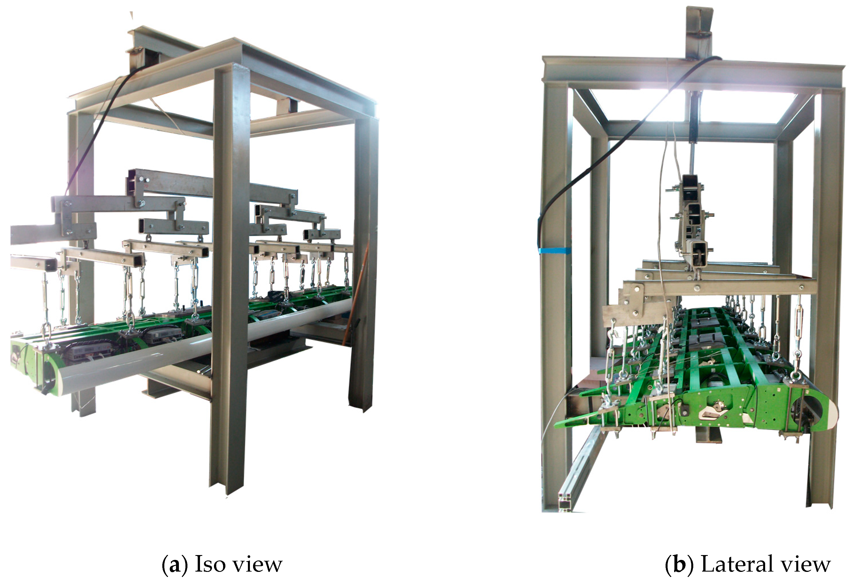
Figure 18.
Whiffletree and rig for static test.

Figure 19.
Detail of the load application (a) and constraints (b) (aft view).

Figure 20.
FBD representation: applied loads and constraints forces and moments.

Figure 21.
Deviation from the baseline configuration at rest: static load of 1520 N.

Figure 22.
Absorbed power under static load.

Figure 23.
Boundary conditions of the GVT.

Figure 24.
Tab normal mode in power on configuration.

Figure 25.
Frequency swept close to the resonance frequency (f = 3.358 Hz).

Figure 26.
Generalized mass comparison.


Table 1.
Actuator main features.
| Specification/Actuator Model | KBMS-14 | |
|---|---|---|
| Continuous Stall Torque | Nm | 2.11 |
| Peak Stall Torque | Nm | 5 |
| Maximum Speed | RPM | 8000 |
| Peak Current | Arms | 10 |
| Weight | Kg | 2.5 |
| Number of Poles | - | 8 |
Table 2.
HD® main features.
| Speed Reducer Model | HFUC-17-2UH | |
|---|---|---|
| Gear Ratio | - | 120 |
| Maximum Torque | Nm | 54 |
| Maximum Speed | RPM | 60 |
| Moment stiffness | Nm/rad | 16 × 103 |
| Weight | Kg | 0.64 |
| Temperature range | °C | 0–60 |
Table 3.
Relative rotations between rib blocks (design values).
| Relative Rotations Between: | Camber Morphing Mode | Tip Deflection |
|---|---|---|
| Rib blocks B0 and B1 | 3° | 0° |
| Rib blocks B1 and B2 | 10.5° | 0° |
| Rib blocks B2 and B3 | 3° | +10°; −10° |
Table 4.
Functionality test protocol.
| Camber Morphing Mode | Tip Deflection Mode |
|---|---|
| Voltage actuators activation; Control switch to desired mode; Actuation up to the target configuration; Actuators stop and acquisition of rib blocks relative rotations; Actuation reverse, up to the baseline configuration; Actuators stop, flap power off, check of the encoders displays for full rotation recovery. | Voltage actuators activation; Control switch to desired mode; Actuation up to the tip down configuration; Actuators stop and acquisition of rib blocks relative rotations; Actuation reverse up to the baseline configuration; Actuation up to the tip up configuration; Actuators stop and acquisition of rib blocks relative rotations; Actuation reverse up to the baseline configuration; Actuators stop, flap power off, check of the encoders displays for full rotation recovery. |
© 2018 by the authors. Licensee MDPI, Basel, Switzerland. This article is an open access article distributed under the terms and conditions of the Creative Commons Attribution (CC BY) license (http://creativecommons.org/licenses/by/4.0/).
Share and Cite
MDPI and ACS Style
Arena, M.; Amoroso, F.; Pecora, R.; Ameduri, S. Electro-Actuation System Strategy for a Morphing Flap. Aerospace 2019, 6, 1. https://doi.org/10.3390/aerospace6010001
AMA Style
Arena M, Amoroso F, Pecora R, Ameduri S. Electro-Actuation System Strategy for a Morphing Flap. Aerospace. 2019; 6(1):1. https://doi.org/10.3390/aerospace6010001
Chicago/Turabian StyleArena, Maurizio, Francesco Amoroso, Rosario Pecora, and Salvatore Ameduri. 2019. "Electro-Actuation System Strategy for a Morphing Flap" Aerospace 6, no. 1: 1. https://doi.org/10.3390/aerospace6010001
Note that from the first issue of 2016, this journal uses article numbers instead of page numbers. See further details here.