Effect of Paper or Silver Nanowires-Loaded Paper Interleaves on the Electrical Conductivity and Interlaminar Fracture Toughness of Composites

1
National Key Laboratory of Advanced Composites, AVIC Composite Technology Center, Beijing 101300, China
2
Faculty of Science & Engineering, University of Nottingham Ningbo China (UNNC), Ningbo 315100, China
*
Author to whom correspondence should be addressed.
Aerospace 2018, 5(3), 77; https://doi.org/10.3390/aerospace5030077
Submission received: 19 June 2018
/
Revised: 17 July 2018
/
Accepted: 17 July 2018
/
Published: 19 July 2018
(This article belongs to the Special Issue ECO-COMPASS: Ecological and Multifunctional Composites for Application in Aircraft Interior and Secondary Structures)
Abstract
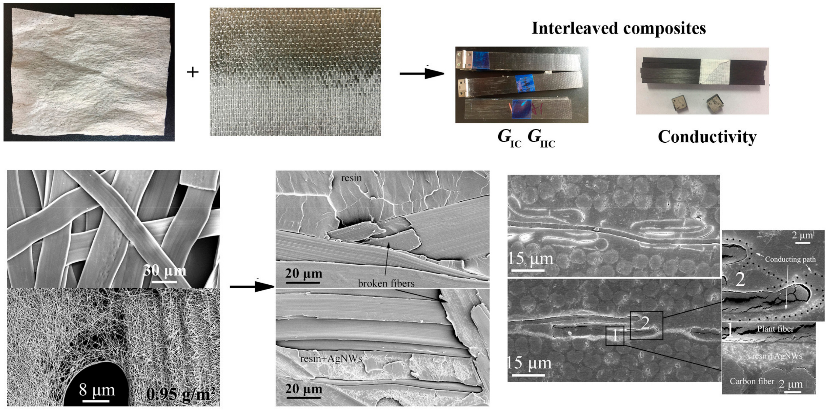
:The effect of plant-fiber paper or silver nanowires-loaded paper interleaves on the electrical conductivity and interlaminar fracture toughness of composites was studied. Highly conductive paper was prepared by surface-loaded silver nanowires. The percolation threshold appeared at about 0.4 g/m2. The surface resistivity reached 2.3 Ω/sq when the areal density of silver nanowires was 0.95 g/m2. After interleaving the conductive papers in the composite interlayers, in-plane electrical conductivity perpendicular to the fiber direction was increased by 171 times and conductivity through thickness direction was increased by 2.81 times. However, Mode I and Mode II interlaminar fracture toughness decreased by 67.3% and 66.9%, respectively. Microscopic analysis showed that the improvement of conductivity was attributable to the formation of an electrical conducting network of silver nanowires which played a role in electrical connection of carbon fiber plies and the interleaving layers. However, the density of the highly packed flat plant fibers impeded the infiltration of resin. The parallel distribution of flat fibers to the carbon plies, and poor resin-fiber interface made the interlaminar fracture occur mainly at the interface of plant fibers and resin inside the interleaves, resulting in a decline of the interlaminar fracture toughness. The surface-loading of silver nanowires further impeded the infiltration of resin in the densely packed plant fibers, resulting in further decline of the fracture toughness.

1. Introduction
Continuous carbon fiber-reinforced resin matrix composites are usually made of continuous carbon fibers as the reinforcement and thermosetting resin as the matrix. Specifically because of their high strength and modulus, these materials are widely used in aerospace and attract an increasing amount of attention in many fields [1]. On the other hand, going green and going functional are the two major themes in material development in the world. To develop greener composites, an increasing number of researchers are focused on the 'greening' of raw materials such as developing bio-based epoxy resin matrix and applying natural fibers as the reinforcement [2,3,4]. To develop functional composites while maintaining their performance, many studies focus on the application of nanomaterials, for instance by improving the conductivity of composites for lightning-strike protection and electromagnetic shielding [5,6,7].
One of the most effective ways to improve the impact resistance of composites is through interleaving technology. Currently, interleaving materials generally use thermoplastic resin particles, thin films and non-woven fabrics [8,9,10,11]. Among these materials, tough and high-strength fibers such as nylon fiber, aramid fiber, carbon nanofiber and their non-wovens are attracting more attention [9,12,13,14]. By introducing micro- and nano-structures into the interlays, new crack propagation mechanisms were introduced to improve the areal density of energy dissipation, thus the interlaminar fracture toughness of the composites was remarkably improved. However, the structures of the interleaves strongly affect the interlaminar toughness of the composite. Palazzetti et al. studied the effects of thickness, orientation and diameter of electrospun nylon6,6 veils on the Mode I (GIC) and Mode II (GIIC) interlaminar fracture toughness of composites [15]. Ramirez et al. studied the interlaminar fracture toughness of composites interleaved with PPS and PEEK veils of different areal densities, linear densities and fiber diameters. They found that GIC and GIIC were increased with the mean coverage, but the polymer types showed nearly no effect [16]. Heijden et al. studied the toughening properties of polycaprolactone interleaves with different non-porous and porous structures. They found the polycaprolactone thin layer of nanofibers had the best performance [17]. KuWata et al. studied the toughening properties of five interleaf veils formed by carbon fibers, polyester fibers, and polyamide fibers and their mixtures [18,19]. Beckermann et al. found that the most important factors of the interleaf layers were the polymer types and areal densities [20]. Daelemans et al. found the orientation of veil fibers strongly affected toughening performance of veils. The laminate interleaved with veils with random fiber orientation had the highest interlaminar fracture toughness [21]. All these studies revealed that the material property, fiber diameter, areal densities, fiber orientation and other structural factors of the interleaved layer showed large or small effect on the toughening performance related to the composite material systems. However, although many studies have been done, the interlayer toughening mechanism is still not thoroughly understood [22].
Combined with the interleaving technology, a functionalized interlayer technology was developed in our previous researches which can simultaneously and effectively improve the interlaminar fracture toughness and the electrical conductivity of composites [23,24]. The principle was constructing an electrical conducting–toughening double functions network in the interlays of composites by interleaving thin sheet formed of micron-sized nylon network and nano-sized silver nanowires network. The loaded highly conductive silver nanowires showed no negative influences on the toughening mechanism, thus the toughness performance of the interleave was well kept. Aside from in our work, the nano-hybrid of interleaf has attracted much attention elsewhere in recent years. Eskizeybek et al. used electrospinning carbon nanotube-polyacrylonitrile (CNT-PAN) hybrid nanofibrous mat as the interleaf to toughening composite. The GIC of the composite was much higher than that interleaved with neat PAN nanofibrous mat [25]. Zhou et al. used hierarchical CNT-short carbon fiber interleaves to improve the GIC of composite [26]. Zheng et al. used carbon nanotubes/polysulfone nanofiber prepared by vacuum filtration as the toughening interleaf [27]. Lee et al. used CNT-enhanced nonwoven carbon tissue as the interleaf and found a significant improvement of GIIC [28]. Although the functions of the materials in these references were not studied, the multi-scale toughening mechanism of different material systems was interesting and still needed to be further explored.
The above also indicates most current research is focused on tough and high-strength artificial fibers. However, although many plant fibers have good mechanical properties and have been used as reinforced fibers [29], the use of plant fibers or papers as interleaving materials to modify composites is rarely reported. Moreover, different from the circular shaped artificial fibers reported before, plant fibers have extremely complex structures, with most of them containing two walls and lumens [30]. Study of the effect of different structures and materials of plant-fiber interleaves can give us a deeper understanding of the interlaminar failure mechanism of composites. The nano-scale effect on the toughening mechanism and the function integration of the composite using nano hybridized plant-fiber interleaf are also interesting.
In this paper, a conductive plant fiber paper was prepared through solution immersion method. Using the papers and conductive papers as the interleaving materials, the interlaminar fracture toughness and conductivity of the modified composites was studied, and the influence mechanism of the multi-scale structures on the interlaminar properties is discussed.
2. Materials and Methods
2.1. Materials
In this study, papers used as interleaves were a kind of thin layer formed by plant fibers, with the main component being cellulose. The thickness of the paper was 16~18 μm. The surface density was 11.26 g/m2. Silver nanowires (AgNWs) were purchased from Beijing NaHui Technology and Trade Co., Ltd. (Beijing, China). The diameter of the silver nanowire was about 40 nm. The length was between 30 μm and 50 μm. The silver nanowires were dispersed in isopropyl alcohol in a concentration of 5 mg/mL. The unidirectional carbon fiber fabric used in this study was U3160 (CCF 300, 3K, areal density: 160 g/m2). The thickness of a single ply was 0.166 mm. The average diameter of the carbon fiber was 7.2 ± 0.3 μm. An aero-grade RTM (resin transfer molding) epoxy resin under the brand 3226, which is a product of AVIC Composites Technology Co., Ltd. (Beijing, China) was chosen as the matrix resin. All other auxiliary materials were purchased from commercial sources.
2.2. Preparation of the Conductive Papers and the Composite Laminates
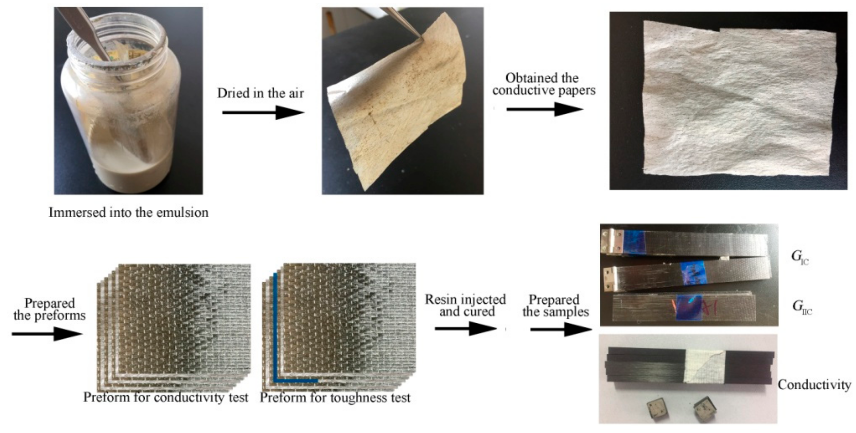
Figure 1 illustrates the preparation process of the conductive papers, composite laminates, and test samples. First, the conductive paper was prepared by immersion method. Then the unidirectional carbon plies were stacked into preforms with one sheet of plain or conductive paper inserted as the interleaf in each interlayer. Finally, the required composites were injected with epoxy resin 3226 and cured at the given RTM molding condition of U3160/3226 composite. The test specimens were prepared according to the corresponding test standards.
To prepare the conductive papers, the plain papers were immersed into the slurry of AgNWs dispersed by isopropanol. After immersion for 5 s at room temperature, the papers were removed from the slurry and dried at room temperature. The conductive papers of different AgNWs areal densities can be obtained by controlling the immersion times. The conductive paper used in this study had an AgNWs areal density of 0.95 g/m2 obtained by performing the immersing and drying process twice.
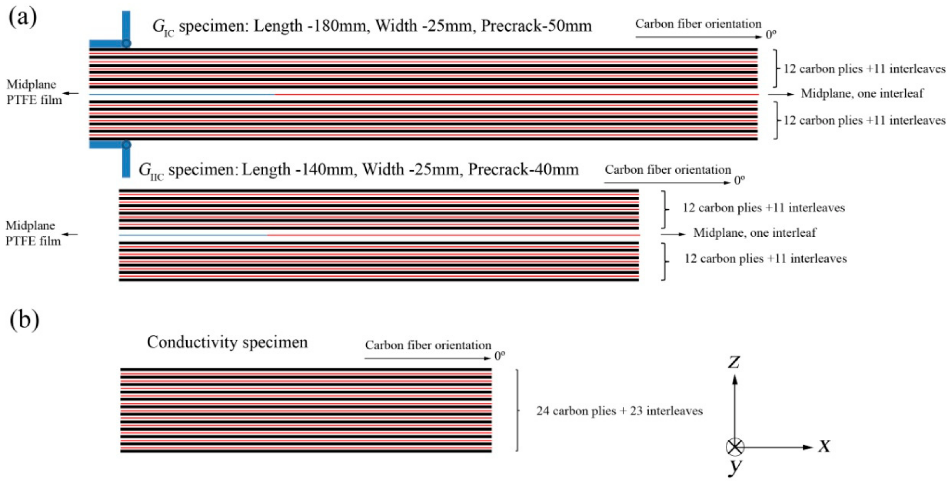
The composite laminates prepared for the conductivity test and interlaminar fracture toughness test were unidirectional with the preform stacked sequence of [0]24 according to specimens for testing (Figure 2). Here [0]24 means total 24 carbon fiber plies were stacked with all the fibers oriented at 0° direction. Each interlayer of the preform was interleaved with one plain paper or conductive paper. To prepare the samples for GIC and GIC tests, a 25 μm thick polytetrafluoroethylene (PTFE) film was inserted into the middle plane of the preform to prefabricate the cracks with controlled length. After being prepared, the preforms were injected with 3226 epoxy resin and cured according to the standard RTM method of U3160/3226 composite. After cooling, the composite laminates were released from the mold, and then the samples were machined according to the test standards.
2.3. Measurement of Mode I and II Fracture Toughness
The characterization method of fracture toughness and conductivity was the same as our previous paper [23]. The specimen geometry is given in Figure 2a. Mode I fracture toughness tests were carried out according to the Chinese Aviation Industry Standard HB 7402-96 using double cantilever beam (DCB) specimens. The specimens had a width of 25 mm and a length of 180 mm. A pre-crack with a length of 50 mm was made by inserting a PTFE film in the midplane. To make a fresh pre-crack, an initial loading was applied to the specimen before testing. The growing length of the fresh pre-crack was controlled to around 20 mm. The specimen was then reloaded, and the loading was stopped after an increment of a delamination crack growth of 10 mm. The process was carried out five times. Three specimens were tested for each sample. GIC was calculated from Equation (1).
where:
- GIC = Mode I interlaminar fracture toughness, J/m2
- m = coefficient
- P = load, N
- δ = load point displacement, mm
- W = specimen width, mm
- a = delamination length, mm.
Mode II fracture toughness tests were performed according to the Chinese Aviation Industry Standard HB 7403-96. The specimens had a width of 25 mm and a length of 180 mm. The length of pre-crack made by a PTFE film was 40 mm. To make a fresh pre-crack, an initial loading was applied to the specimen before testing first. The growth of delamination crack was about 5 mm. The specimen was then also reloaded. Five specimens were tested. GIIC was calculated from Equation (2). A difference is that the crack growth of the GIC test was stable, while the growth of the GIIC test was unstable and faster propagated.
where:
- GIIC = Mode II interlaminar fracture toughness, J/m2
- P = load, N
- δ = load point displacement, mm
- a = delamination length, mm
- W = specimen width, mm
- 2L = support span, mm.
2.4. Measurement of Conductivity
The AgNWs-loaded papers used for the surface resistivity test were 100 mm wide and 100 mm long. The two opposite edges of the paper were silver-painted and then dried. When testing, copper plates were tightly pressed on the silver-painted edges as electrodes. The surface resistivity (Rs) was calculated from the test resistance (R) by Equation (3). The volume resistivity (Rv) was calculated by Equation (4).
Rs = R × width/length
Rv = R × width × thickness/length
Three main directions of the composite for the conductivity test were defined in Figure 2b since most fiber materials had their orientation [31]. The in-plain volume conductivity along the fiber direction (x direction) and perpendicular to the fiber direction (y direction) of the carbon composite laminate was tested on the samples 10 mm wide and 100 mm long. The volume conductivity through-thickness direction (z direction) was measured on the samples 5 mm square. For each orientation five samples were tested. The two opposite surfaces of the composite specimens were silver-painted and dried before test. When testing, two copper plates were tightly pressed on the silver-painted surface as electrodes. The volume resistivity and conductivity (σ) was calculated by Equations (4) and (5) respectively.
σ = 1/Rv
2.5. Characterization of Morphology
Scanning electron microscopy (SEM) images were obtained using a Hitachi S-4800 SEM (Hitachi, Ltd., Tokyo, Japan). All samples for SEM test were coated with a gold layer before the test. The photographs were taken using a smart phone. The optical micrographs were obtained by an Olympus SZ61 optical microscope (Olympus Corporation, Tokyo, Japan).
3. Results
3.1. Preparation of the Conductive Paper
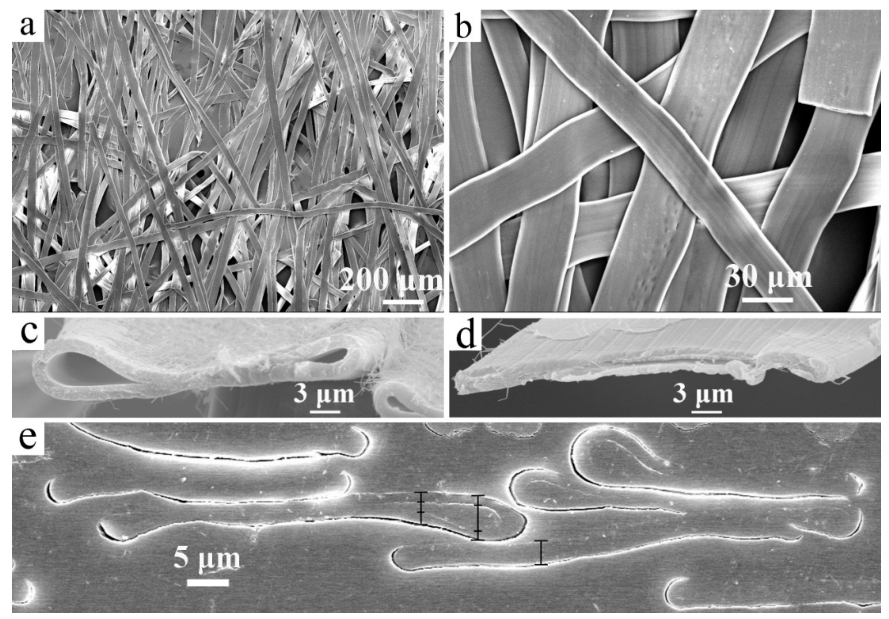
Figure 3 gives the SEM images of the paper. The paper had a thickness of 16~18 μm and areal density of 11.26 g/m2. The paper was formed from a large number of plant fibers overlapping each other. The plant fibers were flat-like and their widths were between 20 μm and 40 μm. A large number of throughout-thickness holes uncovered with fibers existed in the paper because areal density of the paper was small. Figure 3c,d give the cross section of the plant fibers. The plant fiber was hollow with a single wall. The wall thickness was about 1.5 μm. Due to the paper production process involved the extrusion process, all the plant fibers were flattened. Two typical shapes of the flattened fibers are given in Figure 3c,d. The fiber thickness was about 3~5 μm. Figure 3e gives the cross section of the plant fibers embedded in the epoxy resin. It also shows that the thickness of the fiber wall was about 1.5 μm. Some of the plant fibers which were not completely flattened had a larger apparent thickness and epoxy resin was filled into the hollow cores. For those plant fibers completely flattened, the two walls were tightly contacting each other. As seen from Figure 3e, the flattened fibers overlapped each other and the resin had difficulty penetrating their gaps. In addition, the interface bonding between fiber and resin was obviously separated, indicating that interface adhesion was poor.
The conductive paper was obtained by surface-loading AgNWs on the paper using an immersion method which is widely used to prepare functional thin sheets or porous materials such as conductive films, non-woven fabrics, and foams etc. [24,32,33]. Generally, the thin sheet was dipped into the slurry of nanomaterials to absorb a certain amount of dispersive liquid. After being dried, the surface of the thin sheet was covered with a layer of nanomaterials and thus it was functionalized. After being loaded with AgNWs, the color of the paper changed from white to silver gray. However, the AgNWs were only adsorbed on the fiber surface and could be easily removed by ultrasonic treatments. Figure 4a gives the areal density of AgNWs changing with the dipped time. It indicates the areal density was linearly increased with the increase of immersion time. Figure 4b gives the surface resistivity of the paper changed with the areal density of AgNWs. Before being loaded with AgNWs, the paper was obviously electrical insulation material. However, after being loaded with AgNWs, the paper became conductive and its conductivity was gradually increased with the increase of AgNWs areal density. The percolation threshold was found to be near 0.3 g/m2 areal density of AgNWs. To the paper loaded with 0.95 g/cm2 AgNWs, the surface resistivity was typically 2.3 Ω/sq., that is, the volume resistivity was calculated to be 256 S/cm, indicating that the paper had good conductivity with a small AgNWs loading. The conductive paper was still very flexible, and met the requirements of composite processing.
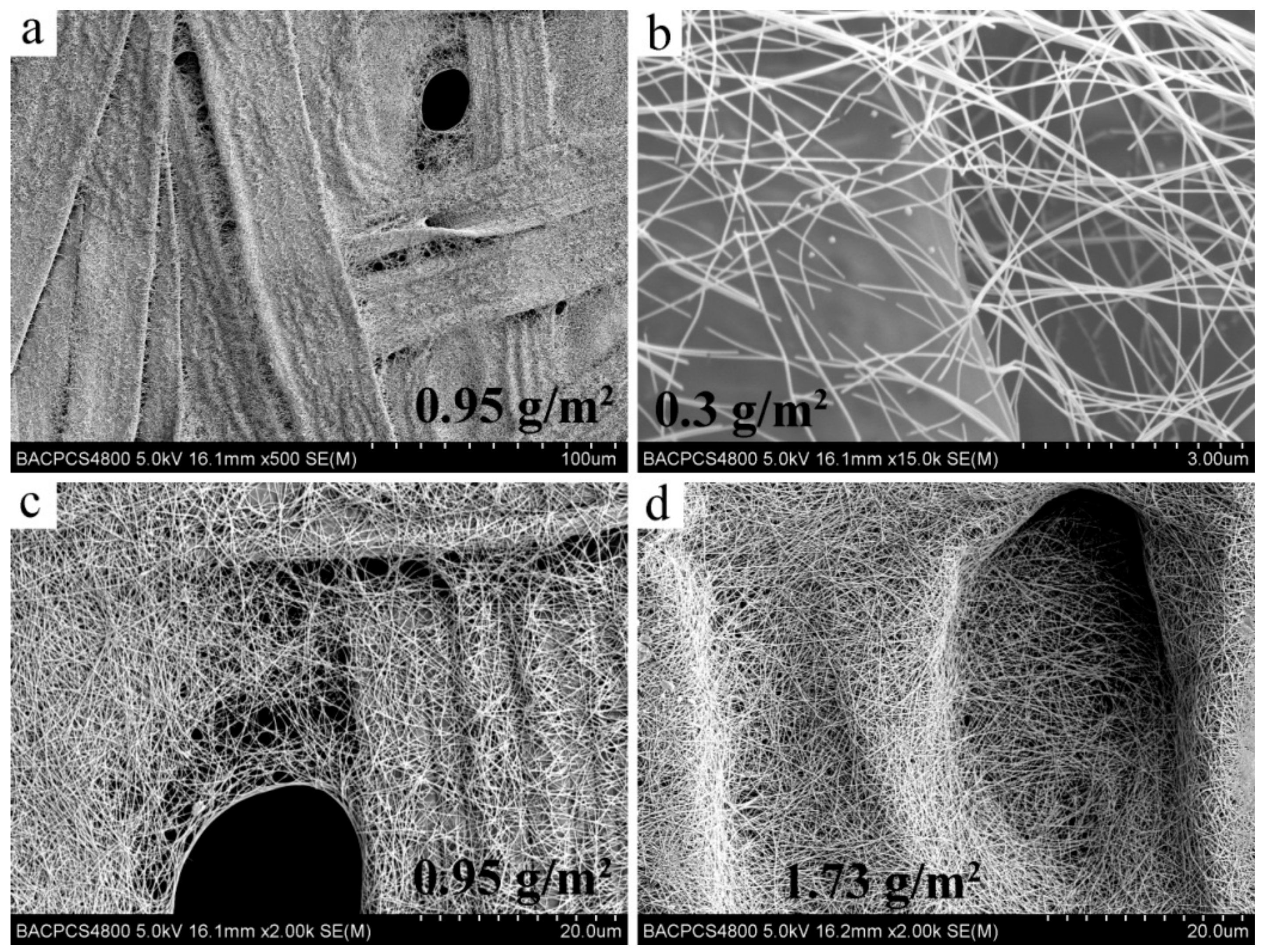
Figure 5 shows the SEM images of the paper after being loaded with AgNWs of different areal densities. Figure 5a gives a large scaled view of the AgNWs-loaded paper with the areal density of 0.95 g/m2. It can be seen that AgNWs were uniformly adsorbed on the surface of the plant fibers, and almost covered all the fiber surface forming a continuous conducting network, thus the paper loaded with AgNWs has a low percolation threshold and good conductivity. Figure 5b–d give the SEM images of the conductive papers with different AgNWs areal densities. For all densities, AgNWs were uniformly distributed on the surface of the paper. With an increase of AgNWs density, the AgNWs network on the paper gradually went from sparse to dense. The plant fibers were barely observed at the AgNWs density of 1.73 g/m2 (Figure 5d). However, no local enrichment of AgNWs was found. It also indicated AgNWs were uniformly distributed even at such a high loading. In addition, in the case of large holes that not covered with plant fibers on the paper (generally larger than 10 μm in length, seen in Figure 5a,c,d), AgNWs bridged across the holes under the capillary of the dispersion. The existence of AgNWs bridging made the AgNWs network distributed on the two opposite surfaces of the paper interconnect and formed a holistic continuous conducting structure. The above results show that we obtained the conductive paper with a continuous and uniform AgNWs conducting network on surface the paper.
3.2. Electrical Conductivity of the Laminates
Three groups of samples containing control, plain papers interleaved, conductive papers interleaved for conductivity test were prepared using RTM method. The stacking sequence of all the samples was [0]24. The final thickness was controlled to 4.0 mm by steel spacers. Table 1 contains a summary of the volume electrical conductivity in the two in-plane directions (σx and σy) and the through-thickness direction (σz) of all these samples.
The in-plane electrical conductivity along the fiber direction (σx) for all the composite samples was about 6 × 10³ S/m. This indicated that the change of σx was very small and σx was mainly depended on the intrinsic conductivity of the carbon fibers because it was much higher than the conductivity of the interleaves.
The in-plane electrical conductivity perpendicular to the fiber direction (σy) of the conductive papers interleaved samples was significantly increased by 171 times and 180 times compared with the control and plain paper interleaved samples respectively. This means σy of the control and plain paper interleaved samples were very close, while σy of conductive papers interleaved sample was significantly higher.
The through-thickness conductivity of the conductive paper interleaved samples reached 17.9 S/m and also significantly increased 2.81 times compared with the control samples, while for the plain paper interleaved samples, the through-thickness direction was nearly insulated. The interleaves played barrier roles in the electrical conduction between carbon fiber layers, leading to the decrease of conductivity. When interleaved with the conductive papers, the laminated carbon fiber layers and the conductive papers formed a series structure. The through-thickness conductivity was mainly limited by the conductivity of the carbon fiber layers because the AgNWs-loaded conductive papers had relatively higher conductivity. The good conductivity of the conductive papers played an effective conducting connection, making the through-thickness conductivity of composite samples greatly improved.
Compared with our previous work [23], the in-plane and out of plain conductivities of composites were smaller. That is because the conductivity was influenced by many factors such as the structural characteristics of the conductive interleaves, the bulk conductivity of carbon fibers, the volume fraction of composites and so on.
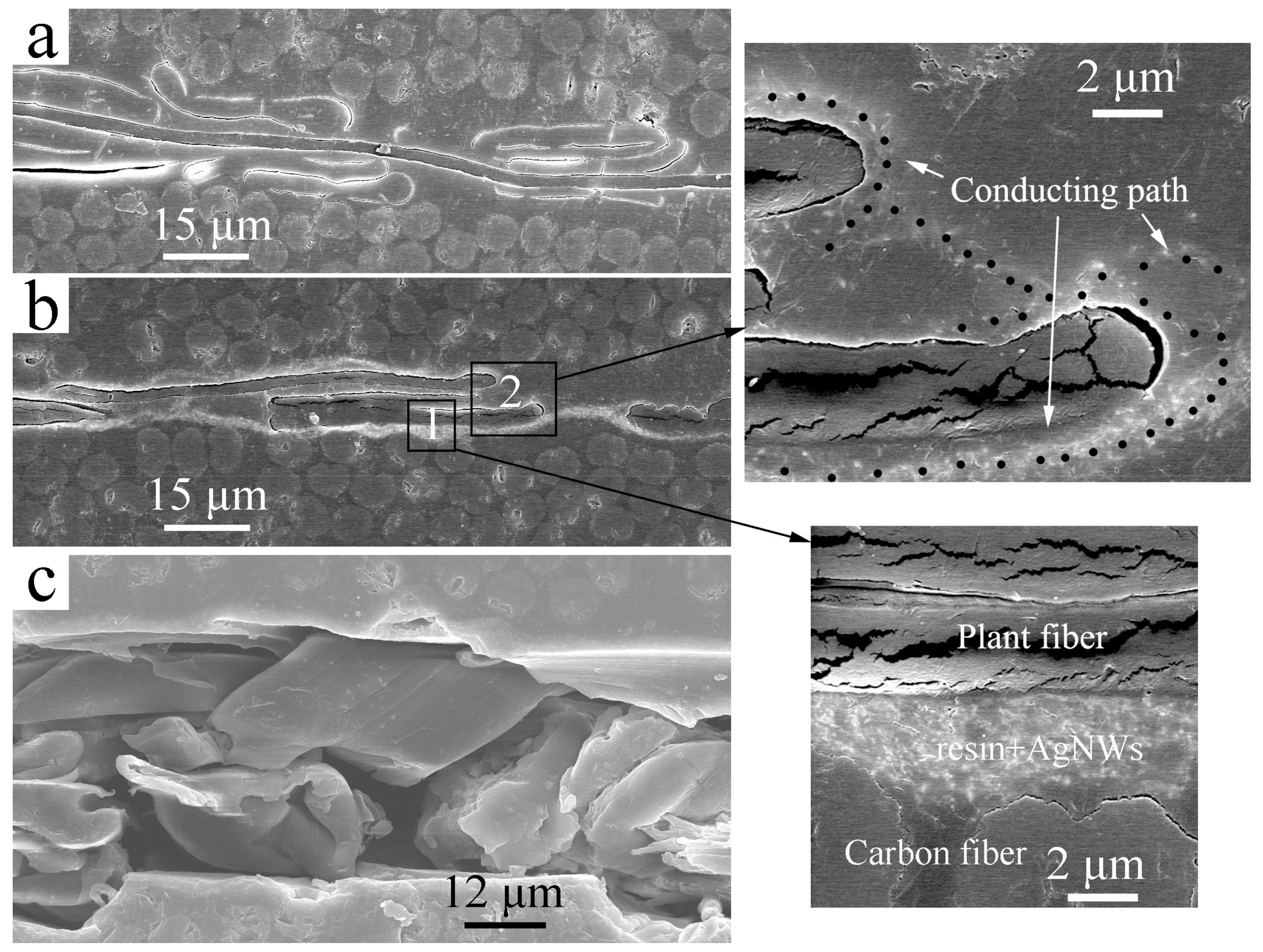
Figure 6a,b give the cross section SEM images of the composites interleaved with plain papers and conductive papers. The interleaves were distributed between two carbon layers with thickness between 5 μm and 25 μm. The different contrast shown in Figure 6b can be assigned to the different phases/structures based on their electrical properties, e.g., non-conductive epoxy resin region was dark while the AgNWs region was much brighter [34,35]. Comparing Figure 6a,b, relatively bright zones on the surface of the plant fibers of the conductive paper were found due to the high conductivity of AgNWs in the epoxy resin (see the enlarged images of the regions 1 and 2). The loading of AgNWs on the surface of the paper showed nearly no effect on the thickness of the interlayer. The conducting paths on the opposite faces of the paper formed by AgNWs-doped epoxy resin were connected in the hole not covered with plant fibers shown in the enlarged image of Region 2. Thus, a continuous conducting structure on the whole surface of the interleave was formed. As seen from the enlarged image of Region 1, the conducting path had good electrical contact with carbon fibers, so it played a role in connecting the two carbon layers. AgNWs were well and uniformly distributed on the surface of paper, indicating the conducting nano-sized network was well kept after stacking, resin injection and curing process. Figure 6c is the cross section image of the composite with an open crack. After wearing during the sample preparation process, the plant fiber was stripped from the matrix resin, indicating a poor bonding between the plant fiber and the resin which was agreed with the poor interface shown in Figure 3e and Figure 6a,b . Usually this was because the plant fibers were hydrophilic and incompatible with epoxy resin.
3.3. Interlaminar Fracture Toughness of the Laminates
Table 2 shows the interlaminar fracture toughness of all the samples in terms of Mode I (GIC) and Mode II (GIIC), respectively. The final thicknesses of all laminates were controlled to be around 4.0 mm, which satisfies the nominal carbon fiber volume fraction. However, after being interleaved with plain papers or conductive papers, Mode I and Mode II interlaminar fracture toughness decreased significantly. GIC decreased from 321.1 J/cm2 to 111.1 J/cm2 (−65.4%) and 104.8 J/cm2 (−67.4%) and GIC decreased from 1293 J/cm2 to 541 J/cm2 (−58.2%) and 428 J/cm2 (−66.9%) respectively. This indicated that the interleaves did not toughen the composites; however, they played a “defect” role in the interlayers. The interlaminar fracture toughness was further smaller to the AgNWs-loaded papers interleaved composite.
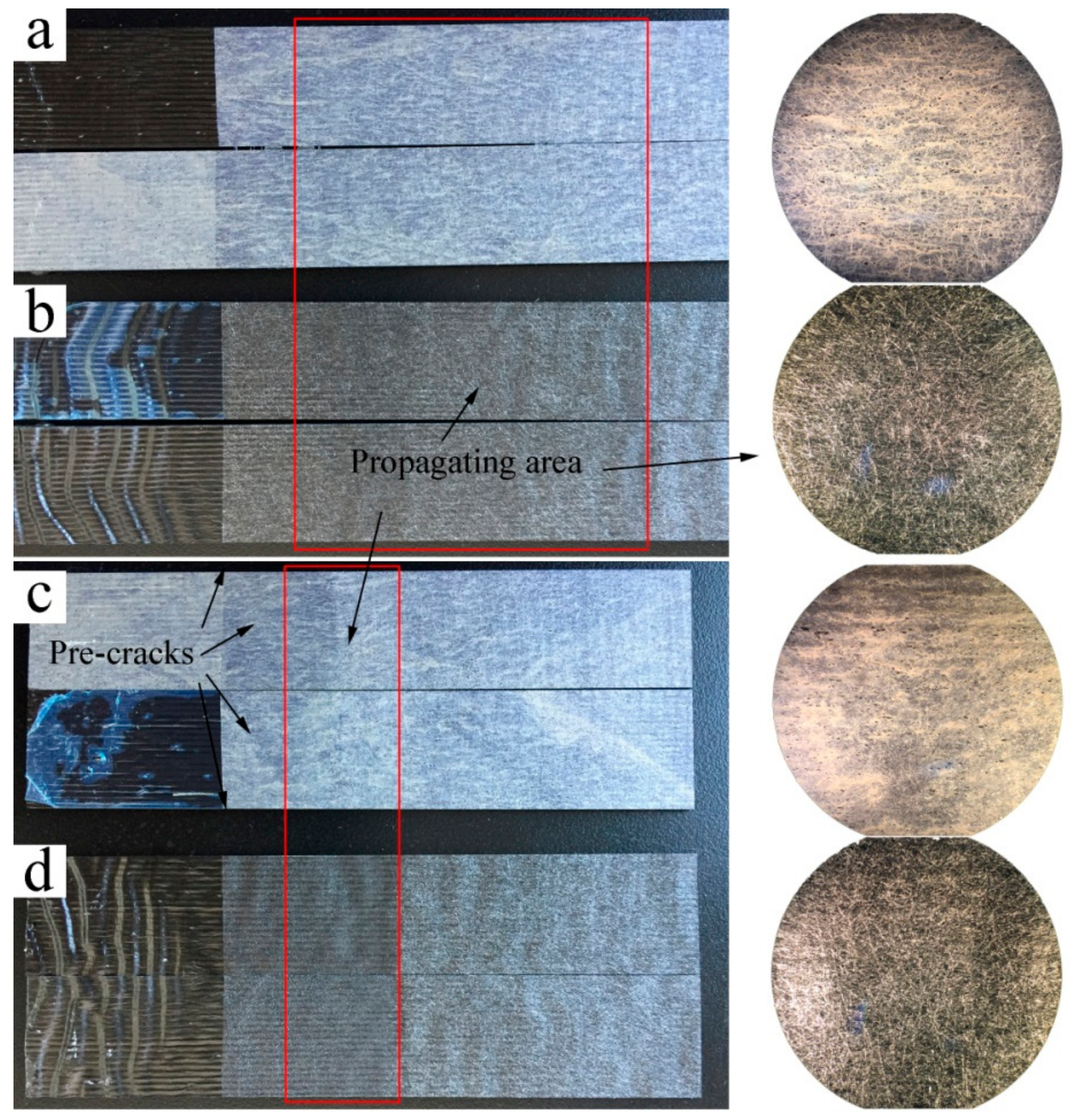
Figure 7 gives the optical images and micrographs of the Mode I and Mode II fracture surfaces of the papers and conductive papers interleaved composites. As can be clearly seen from the figure, all the fracture surfaces occurred inside the interleaves, which means a similar fracture mechanism for the different interleaves. In addition, the fracture surface of the conductive paper interleaved composites was relatively whitish, probably because of the existing of AgNWs or the insufficient infiltration of epoxy inside the conductive paper.
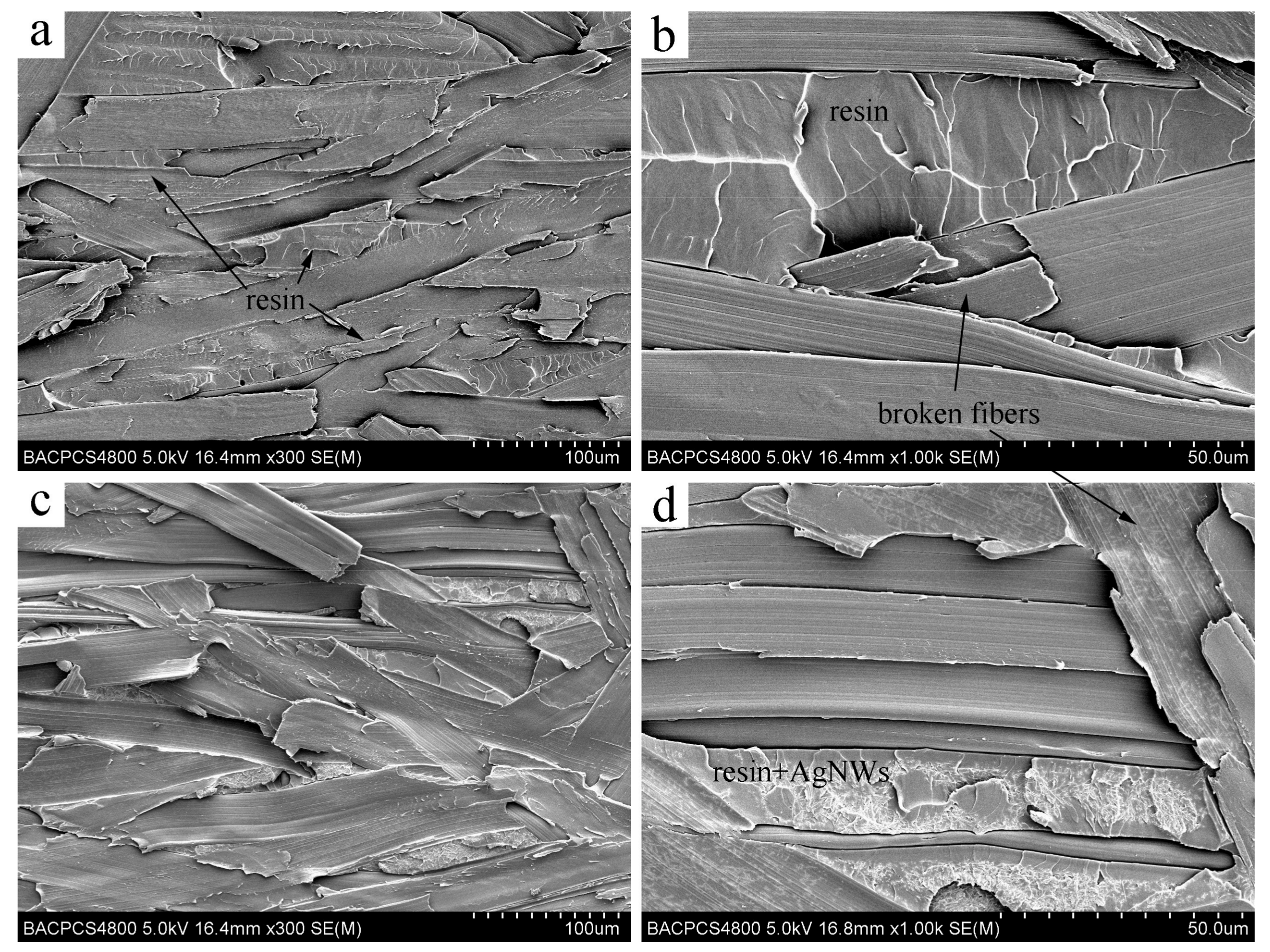
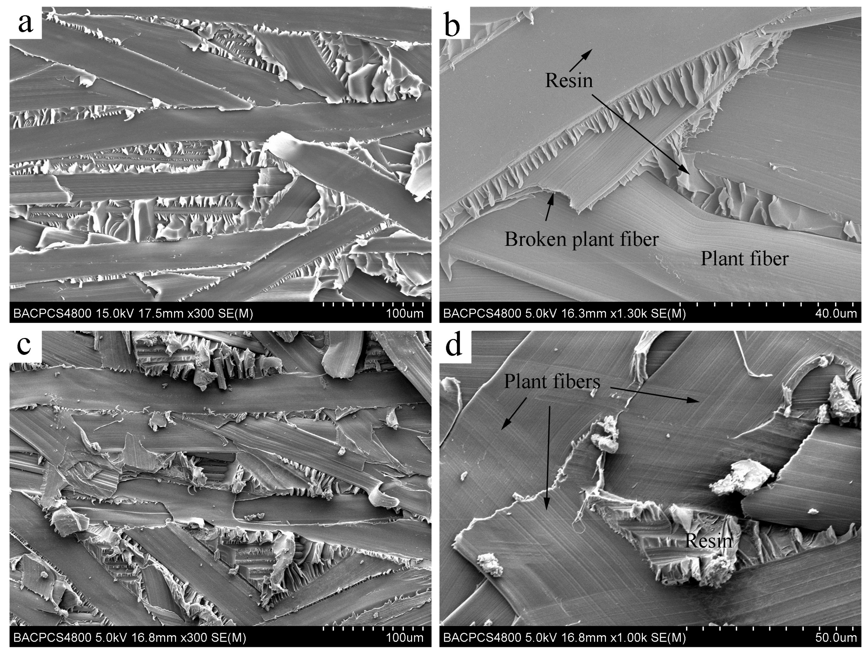
Figure 8 gives the SEM images of the Mode I fracture surfaces. It was found that all the Mode I fracture surfaces were covered with plant fibers, that is, the failure mainly occurred inside the interleave layers. Compared with the structure of nylon veil [23], the flattened plant fibers of the paper stacked more densely. More fibers were distributed per unit volume, and more parallel to the carbon plies. From Figure 8a,c, most of the interlaminar failures occurred in the plant fiber–epoxy resin interfaces or the overlapped areas of plant fibers. Compared with Figure 3e and Figure 6a,b , because of the flat shape and highly packed density of the plant fibers, we can see the epoxy resin had not completely penetrated into the overlapped areas of the plant fibers. In addition, poor interface between plant fiber and resin was found, thus it was much easier for the fracture to occur inside the interleaves. Besides, the surface of plant fibers or resin on the failure surface was very smooth, and no destroyed resin particles were found, also indicating that the interfacial bonding between paper fiber and resin was weak. Only a few plant fibers were destroyed, as can be seen in Figure 8b,d. In the case of the AgNWs-loaded paper interleaved sample, AgNWs can easily be seen at the resin area of fracture surface shown in Figure 8d. However, this area has became more rough indicating that the resin had relatively poor infiltration in the AgNWs-enriched area.
Compared with Figure 8a,c, resin may be easily seen in the gap of the overlapped plant fibers in Figure 8a, while the resin was small in quantity except for the area not covered with plant fiber, and more bare plant fibers are found in Figure 8c. This indicates that the presence of AgNWs concentrated on the surface of the interleaved paper greatly reduced the permeability of the resin into the densely packed plant fibers, making the interlayer much liable to be destroyed when not filled with resin, and thus the Mode I fracture toughness of the conductive papers interleaved composite was lower than the plain papers interleaved composite.
Figure 9 gives the SEM images of the Mode II fracture surfaces. It can also be seen from the images that most of the Mode II fractures occurred inside the interleave layers of the composites. Only in the area not covered with plant fibers, shear failure of resin was observed at the interface between the carbon ply and the interlayer. As seen from Figure 9a,c, fracture failure at plant fiber–resin interfaces, paper fiber–paper fiber interfaces obviously exist everywhere. As seen from Figure 9b,d, the fracture failure of plain paper interleaved composite mostly occurred at the fiber-resin interfaces while that of conductive paper interleaved composite mostly occurred at the non-resin infiltrated fiber–fiber overlapped areas. More surfaces of plant fibers were found and little resin existed in the gap of plant fibers as seen in Figure 9c,d, which are very different from the fracture surfaces shown in Figure 9a,b. This indicates that the presence of AgNWs impeded the impregnation of resin in densely packed paper fibers, leading to the further decline of Mode II interlaminar fracture toughness.
4. Discussion
It was proved that the electrical conductivity and fracture toughness of the composite can be simultaneously improved using the conducting–toughening integrated interleaves [23]. However, from the results in this paper, the structure of function integrated interleaves still requires more study.
To improve the electrical conductivity, the continuity of the conducting network which played a role in electrical connection of different carbon fibers was very important. On the surface of the conductive paper in this study, AgNWs formed a continuous and uniform conducting network, making the paper highly conductive at a low AgNWs loading. The porous form of the paper made the conductive networks on the opposite surfaces of the paper interconnected, thus the interleaves effectively connected the different carbon plies, resulting in improvement of the through-thickness conductivity of the composite.
With the interlaminar toughening of composites, a fracture usually occurs in the path of least energy dissipation. The toughening performance of the interleave is closely related to its material properties and structural properties. The toughening mechanism generally includes viscoelastic energy dissipation, bridging the effect of particles or fibers, and crack deflection caused by defects or rigid interfaces. When a fracture path propagates through areas with these effects, energy dissipation per unit area is increased and the fracture path becomes more circuitous, resulting in an increase of fracture toughness. For example, as a successful application of ex situ toughening, the toughening mechanism of PEK-C film was the formation of a double continuous structure containing thermoplastic rich phase and thermosetting rich phase. The higher viscoelastic energy dissipation of thermoplastic rich phase and the crack deflection between two-phase interface increased energy dissipation of the crack propagation. With the nylon veil interleaved composites, the bridging effect of ductile nylon fibers was the main factor.
Compared with the circular artificial nylon fibers, the plant fibers were flattened. This made the packing density much higher and the plant fiber orientation was more parallel to the carbon plies. Epoxy resin had more difficulty penetrating into such closely packed narrow gaps between plant fibers. Less fiber bridging also occurred because of its parallel orientation during fracture. On the other hand, because of the strongly hydrophilic characteristic of plant fiber, the interface between plant fiber and epoxy resin was poor. Combined the above factors, the interlaminar failure mostly occurred in fiber-resin interface and non-resin infiltrated fiber–fiber overlapped area where the energy dissipation per unit area was much lower, thus the interlaminar fracture toughness was significantly decreased. With the AgNWs-loaded papers interleaved composites, a large number of AgNWs formed a nanoscaled network on the surface of densely packed plant fibers, which was very different from the AgNWs-loaded nylon veil interleaved composite, with which the AgNWs network mostly covered single nylon fibers and bridged between fibers, further reducing the penetration of resin in the interior of paper, so interlaminar failure occurred in non-resin infiltrated fiber–fiber overlapping areas and led to the further decline of interlaminar fracture toughness.
In addition, although interlaminar toughness was decreased after interleaving with papers made of plant fibers, the result can provide us with some useful inspirations. For example, we could use flax fiber, which is much stronger and nearly circular to improve the fiber fracture energy and infiltration of resin. Additionally, the surface treatment is required to improve the bonding of fiber and resin. The sound absorption and damping properties of composites interleaved with plant fibers may also be very interesting.
5. Conclusions
In conclusion, through preparing conductive papers and using as interleaves, the electrical conductivity of composites was effectively improved, but the interlaminar fracture toughness was obviously decreased. The increase of conductivity was achieved from the good conductivity of AgNWs network and good electrical connection between AgNWs network and carbon plies. The decrease of the interlaminar fracture toughness can be attributed to highly parallel, densely packed interleaf structure formed by the flattened plant fibers and the poor interface between plant fibers and epoxy resin. The highly parallel distribution of plant fiber and its poor bonding with resin caused the fracture path to mainly propagate on the peeling surfaces of epoxy resin–plant fiber and plant fiber–plant fiber. Few plant fibers were destroyed during facture to dissipate energy. The densely packed plant fibers impeded the penetration of resin inside the paper and the penetration became worse for the paper with AgNWs surface loaded. All these reasons resulted the decrease of interlaminar fracture toughness.
Author Contributions
X.Y. conceived and guided the project and study; M.G. performed the experiments and wrote the paper.
Funding
Financial supports from National 973 Project 2010CB631100 and the Aeronautical Science Foundation of China under Projects 2016ZFV8010 are gratefully acknowledged.
Conflicts of Interest
The authors declare no conflicts of interest.
References
- Lubineau, G.; Rahaman, A. A review of strategies for improving the degradation properties of laminated continuous-fiber/epoxy composites with carbon-based nanoreinforcements. Carbon 2012, 50, 2377–2395. [Google Scholar] [CrossRef]
- Cicala, G.; Pergolizzi, E.; Piscopo, F.; Carbone, D.; Recca, G. Hybrid composites manufactured by resin infusion with a fully recyclable bioepoxy resin. Composites Part B 2018, 132, 69–76. [Google Scholar] [CrossRef]
- Ma, S.; Li, T.; Liu, X.; Zhu, J. Research progress on bio-based thermosetting resins. Polym. Int. 2016, 65, 164–173. [Google Scholar] [CrossRef]
- Chegdani, F.; Mansori, M.E.; Mezghani, S.; Montagne, A. Scale effect on tribo-mechanical behavior of vegetal fibers in reinforced bio-composite materials. Composites Science and Technology. Compos. Sci. Technol. 2017, 150, 87–94. [Google Scholar] [CrossRef]
- Zhang, D.; Ye, L.; Deng, S.; Zhang, J.; Tang, Y.; Chen, Y. CF/EP composite laminates with carbon black and copper chloride for improved electrical conductivity and interlaminar fracture toughness. Compos. Sci. Technol. 2012, 72, 412–420. [Google Scholar] [CrossRef]
- Kim, H.S.; Hahn, H.T. Graphite fiber composites interlayered with single-walled carbon nanotubes. J. Compos. Mater. 2011, 45, 1109–1120. [Google Scholar] [CrossRef]
- Garcia, E.J.; Wardle, B.L.; Hart, A.J.; Yamamoto, N. Fabrication and multifunctional properties of a hybrid laminate with aligned carbon nanotubes grown In Situ. Compos. Sci. Technol. 2008, 68, 2034–2041. [Google Scholar] [CrossRef]
- Sun, S.; Guo, M.; Yi, X. Phase separation morphology and mode II interlaminar fracture toughness of bismaleimide laminates toughened by thermoplastics with triphenylphosphine oxide group. Sci. China Technol. Sci. 2017, 60, 444–451. [Google Scholar] [CrossRef]
- Sun, L.; Warren, G.L.; Davis, D.; Sue, H.-J. Nylon toughened epoxy/SWCNT composites. J. Mater. Sci. 2011, 46, 207–214. [Google Scholar] [CrossRef]
- Groleau, M.R.; Shi, Y.-B.; Yee, A.F.; Bertram, J.L.; Sue, H.J.; Yang, P.C. Mode II fracture of composites interlayered with nylon particles. Compos. Sci. Technol. 1996, 56, 1223–1240. [Google Scholar] [CrossRef]
- Yi, X.; Cheng, Q.; Liu, Z. Preform-based toughening technology for RTMable high-temperature aerospace composites. Sci. China Technol. Sci. 2012, 55, 2255–2263. [Google Scholar] [CrossRef]
- Anand, A.; Kumar, N.; Harshe, R.; Joshi, M. Glass/epoxy structural composites with interleaved nylon 6/6 nanofibers. J. Compos. Mater. 2017, 51, 3291–3298. [Google Scholar] [CrossRef]
- Yadav, S.N.; Kumar, V.; Verma, S.K. Fracture toughness behavior of carbon fibre epoxy composite with Kevlar reinforced interleave. Mater. Sci. Eng. B 2006, 132, 108–112. [Google Scholar] [CrossRef]
- Khan, S.U.; Kim, J.-K. Improved interlaminar shear properties of multiscale carbon fiber composites with bucky paper interleaves made from carbon nanofibers. Carbon 2012, 50, 5265–5277. [Google Scholar] [CrossRef]
- Palazzetti, R.; Yan, X.; Zucchelli, A. Influence of geometrical features of electrospun nylon6, 6 interleave on the CFRP laminates mechanical properties. Polym. Compos. 2014, 35, 137–150. [Google Scholar] [CrossRef]
- Ramirez, V.A.; Hogg, P.J.; Sampson, W.W. The influence of the nonwoven veil architectures on interlaminar fracture toughness of the interleaved composites. Compos. Sci. Technol. 2015, 110, 103–110. [Google Scholar] [CrossRef]
- Heijden, S.; Daelemans, L.; Meireman, T.; Baere, I.D.; Rahier, H.; Paepegem, W.V.; Clerck, K.D. Interlaminar toughening of resin transfer molded laminates by electrospun polycaprolactone structures: Effect of the interleave morphology. Compos. Sci. Technol. 2016, 136, 10–17. [Google Scholar] [CrossRef]
- KuWata, M.; Hogg, P.J. Interlaminar toughness of interleaved CFRP using non-woven veils: Part 1. Mode-I testing. Composites Part A 2011, 42, 1551–1559. [Google Scholar] [CrossRef]
- KuWata, M.; Hogg, P.J. Interlaminar toughness of interleaved CFRP using non-woven veils: Part 2. Mode-II testing. Composites Part A 2011, 42, 1560–1570. [Google Scholar] [CrossRef]
- Beckermann, G.W.; Pickering, K.L. Mode I and Mode II interlaminar fracture toughness of composite laminates interleaved with electrospun nanofibre veils. Composites Part A 2015, 72, 11–21. [Google Scholar] [CrossRef] [Green Version]
- Daelemans, L.; Heijden, S.; Baere, I.D.; Rahier, H.; Paepegem, W.V.; Clerck, K.D. Using aligned nanofibres for identifying the toughening micromechanisms in nanofibre interleaved laminates. Compos. Sci. Technol. 2016, 124, 17–26. [Google Scholar] [CrossRef]
- Daelemans, L.; Heijden, S.; Baere, I.D.; Rahier, H.; Paepegem, W.V.; Clerck, K.D. Nanofibre bridging as a toughening mechanism in carbon/epoxy composite laminates interleaved with electrospun polyamide nanofibrous veils. Compos. Sci. Technol. 2015, 117, 244–256. [Google Scholar] [CrossRef]
- Guo, M.; Yi, X.; Liu, G.; Liu, L. Simultaneously increasing the electrical conductivity and fracture toughness of carbon-fiber composites by using silver nanowires-loaded interleaves. Compos. Sci. Technol. 2014, 97, 27–33. [Google Scholar] [CrossRef]
- Guo, M.; Yi, X. The production of tough, electrically carbon fiber composite laminates for use in airframe. Carbon 2013, 58, 241–244. [Google Scholar] [CrossRef]
- Eskizeybek, V.; Yar, A.; Avcı, A. CNT-PAN hybrid nanofibrous mat interleaved carbon/epoxy laminates with improved Mode I interlaminar fracture toughness. Compos. Sci. Technol. 2018, 157, 30–39. [Google Scholar] [CrossRef]
- Zhou, H.; Du, X.; Liu, H.-Y.; Zhou, H.; Zhang, Y.; Mai, Y.-W. Delamination toughening of carbon fiber/epoxy laminates by hierarchical carbon nanotube-short carbon fiber interleaves. Compos. Sci. Technol. 2017, 140, 46–53. [Google Scholar] [CrossRef]
- Zheng, N.; Huang, Y.; Liu, H.-Y.; Gao, J.; Mai, Y.-W. Improvement of interlaminar fracture toughness in carbon fiber/epoxy composites with carbon nanotubes/polysulfone interleaves. Compos. Sci. Technol. 2017, 140, 8–15. [Google Scholar] [CrossRef]
- Lee, S.-H.; Kim, H.; Hang, S.; Cheong, S.-K. Interlaminar fracture toughness of composite laminates with CNT-enhanced nonwoven carbon tissue interleave. Compos. Sci. Technol. 2012, 73, 1–8. [Google Scholar] [CrossRef]
- Chen, C.Z.; Li, Y.; Yu, T. Interlaminar toughening in flax fiber-reinforced composites interleaved with carbon nanotube buckypaper. J. Reinf. Plast. Compos. 2014, 33, 1859–1868. [Google Scholar] [CrossRef]
- Ramamoorthy, S.K.; Skrifvars, M.; Persson, A. A review of natural fibers used in biocomposites: Plant, animal and regenerated cellulose fibers. Polym. Rev. 2015, 55, 107–162. [Google Scholar] [CrossRef]
- Cesano, F.; Zaccone, M.; Armentano, I.; Cravanzola, S.; Muscuso, L.; Torre, L.; Kenny, J.M.; Monti, M.; Scarano, D. Relationship between morphology and electrical properties in PP/MWCNT composites: Processing-induced anisotropic percolation threshold. Mater. Chem. Phys. 2016, 180, 284–290. [Google Scholar] [CrossRef]
- Ge, J.; Yao, H.-B.; Wang, X.; Ye, Y.-D.; Wang, J.-L.; Wu, Z.-Y.; Liu, J.-W.; Fan, F.-J.; Gao, H.-L.; Zhang, C.-L.; et al. Stretchable conductors based on silver nanowires: Improved performance through a binary network design. Angew. Chem. Int. Ed. 2013, 52, 1654–1659. [Google Scholar] [CrossRef] [PubMed]
- Wu, C.; Fang, L.; Huang, X.; Jiang, P. Three-dimensional highly conductive graphene-silver nanowire hybrid foams for flexible and stretchable conductors. ACS Appl. Mater. Interfaces 2014, 6, 21026–21034. [Google Scholar] [CrossRef] [PubMed]
- Haznedar, G.; Cravanzola, S.; Zanetti, M.; Scarano, D.; Zecchina, A.; Cesano, F. Graphite nanoplatelets and carbon nanotubes based polyethylene composites: Electrical conductivity and morphology. Mater. Chem. Phys. 2013, 143, 47–52. [Google Scholar] [CrossRef] [Green Version]
- Cesano, F.; Rattalino, I.; Demarchi, D.; Bardelli, F.; Sanginario, A.; Gianturco, A.; Veca, A.; Viazzi, C.; Castelli, P.; Scarano, D.; et al. Structure and properties of metal-free conductive tracks on polyethylene/multiwalled carbon nanotube composites as obtained by laser stimulated percolation. Carbon 2013, 61, 63–71. [Google Scholar] [CrossRef]
Figure 1.
Schematic diagram of preparation of conductive papers, composite laminates and test specimens.
Figure 1.
Schematic diagram of preparation of conductive papers, composite laminates and test specimens.

Figure 2.
Schematic map of the specimen geometries for fracture toughness and conductivity testing. (a) GIC and GIIC specimens; (b) conductivity specimen.
Figure 2.
Schematic map of the specimen geometries for fracture toughness and conductivity testing. (a) GIC and GIIC specimens; (b) conductivity specimen.

Figure 3.
SEM images of (a,b) paper; (c,d) cross section of a plant fiber; (e) cross section of paper embedded in epoxy resin.
Figure 3.
SEM images of (a,b) paper; (c,d) cross section of a plant fiber; (e) cross section of paper embedded in epoxy resin.

Figure 4.
(a) Areal density of AgNWs versus immersion times in AgNWs slurry of paper; (b) Surface resistivity of paper versus areal density of AgNWs.
Figure 4.
(a) Areal density of AgNWs versus immersion times in AgNWs slurry of paper; (b) Surface resistivity of paper versus areal density of AgNWs.

Figure 5.
SEM images of the conductive papers with different AgNWs areal densities. (a) 0.95 g/m2, a large scaled view; (b) 0.3 g/m2; (c) 0.95 g/m2, a small scaled view; (d) 1.73 g/m2.
Figure 5.
SEM images of the conductive papers with different AgNWs areal densities. (a) 0.95 g/m2, a large scaled view; (b) 0.3 g/m2; (c) 0.95 g/m2, a small scaled view; (d) 1.73 g/m2.

Figure 6.
SEM images of the cross section of the interleaved composites. (a) Interleaved with plain paper; (b) Interleaved with conductive paper. Region 1: An enlarged image of the area between carbon fibers and plant fiber. Region 2: The conducting path formed by AgNWs; (c) Polished plain paper interleaved sample with an open crack.

Figure 7.
Optical photos and optical microscope photographs of failure surfaces after Mode I and Mode II fracture toughness test. (a) conductive papers interleaved, Mode I fracture surface; (b) plain papers interleaved, Mode I fracture surface; (c) conductive papers interleaved, Mode II fracture surface; (d) plain papers interleaved, Mode II fracture surface.

Figure 8.
SEM images of Mode I fracture surfaces of (a,b) plain paper interleaved composite and (c,d) conductive paper interleaved composite.
Figure 8.
SEM images of Mode I fracture surfaces of (a,b) plain paper interleaved composite and (c,d) conductive paper interleaved composite.

Figure 9.
SEM images of Mode II fracture surfaces of (a,b) plain papers interleaved composite and (c,d) conductive papers interleaved composite.
Figure 9.
SEM images of Mode II fracture surfaces of (a,b) plain papers interleaved composite and (c,d) conductive papers interleaved composite.


Table 1.
Electrical conductivity of composite laminates samples studied.
| Samples | In-Plain | Out of Plain | Fiber Volume Fraction Vf (%) | |
|---|---|---|---|---|
| σx (S/m) | σy (S/m) | σz (S/m) | ||
| Control, no interleaf | ~6 × 10³ | 9.7 | 4.7 | 54.7 |
| Interleaved with plain papers | ~6 × 10³ | 9.2 | <1.3 × 10⁻⁶ | 54.7 |
| Interleaved with AgNWs-loaded papers | ~6 × 10³ | 1.67 × 10³ | 17.9 | 54.7 |
Table 2.
Mode I and II fracture toughness of non-interleaved and interleaved laminates.
| Samples | GIC (J/m2) | GIIC (J/m2) |
|---|---|---|
| Control, no interleaf 1 | 321.1 | 1293 |
| Interleaved with plain papers | 111.1 ± 2.6 | 541 ± 55 |
| Interleaved with AgNWs-loaded papers | 104.8 ± 6.7 | 428 ± 19 |
1 Data from the internal report of our lab.
© 2018 by the authors. Licensee MDPI, Basel, Switzerland. This article is an open access article distributed under the terms and conditions of the Creative Commons Attribution (CC BY) license (http://creativecommons.org/licenses/by/4.0/).
Share and Cite
MDPI and ACS Style
Guo, M.; Yi, X. Effect of Paper or Silver Nanowires-Loaded Paper Interleaves on the Electrical Conductivity and Interlaminar Fracture Toughness of Composites. Aerospace 2018, 5, 77. https://doi.org/10.3390/aerospace5030077
AMA Style
Guo M, Yi X. Effect of Paper or Silver Nanowires-Loaded Paper Interleaves on the Electrical Conductivity and Interlaminar Fracture Toughness of Composites. Aerospace. 2018; 5(3):77. https://doi.org/10.3390/aerospace5030077
Chicago/Turabian StyleGuo, Miaocai, and Xiaosu Yi. 2018. "Effect of Paper or Silver Nanowires-Loaded Paper Interleaves on the Electrical Conductivity and Interlaminar Fracture Toughness of Composites" Aerospace 5, no. 3: 77. https://doi.org/10.3390/aerospace5030077
Note that from the first issue of 2016, this journal uses article numbers instead of page numbers. See further details here.