
Disturbance-Observer-Based Dual-Position Feedback Controller for Precision Control of an Industrial Robot Arm

School of Mechanical Engineering, Chungnam National University, Daejeon 34134, Republic of Korea
*
Author to whom correspondence should be addressed.
Actuators 2022, 11(12), 375; https://doi.org/10.3390/act11120375
Submission received: 21 November 2022
/
Revised: 7 December 2022
/
Accepted: 13 December 2022
/
Published: 14 December 2022
(This article belongs to the Special Issue Modeling, Optimization and Control of Robotic Systems)
Abstract
:Recently, the fourth industrial revolution has accelerated the application of multiple degrees-of-freedom (DOF) robot arms in various applications. However, it is difficult to utilize robot arms for precision motion control because of their low stiffness. External loads applied to robot arms induce deflections in the joints and links, which deteriorates the positioning accuracy. To solve this problem, control methods using a disturbance observer (DOB) with an external sensory system have been developed. However, external sensors are expensive and have low reliability because of noise and reliance on the surrounding environment. A disturbance-observer-based dual-position feedback (DOB-DPF) controller is proposed herein to improve the positioning accuracy by compensating for the deflections in real time using only an internal sensor. The DOB was designed to derive the unpredictable disturbance torque applied to each joint using the command voltage generated by the position controller. The angular deflection of each joint was calculated based on the disturbance torque and joint stiffness, which were identified experimentally. The DPF controller was designed to control the joint motor while simultaneously compensating for angular deflection. A five-DOF robot arm testbed with a position controller was constructed to verify the proposed controller. The contouring performance of the DOB-DPF controller was compared with that of a conventional position controller with an external load applied to the end effector. The increases in the root mean square values of the contour errors were 1.71 and 0.12 mm with a conventional position controller and the proposed DOB-DPF controller, respectively, after a 2.2 kg weight was applied to the end effector. The results show that the contour error caused by the external load is effectively compensated for by the DOB-DPF controller without an external sensor.
1. Introduction
Industrial robot arms are used in various industrial applications for transfer and assembly tasks. Recently, multiple-degree-of-freedom (DOF) robot arms have been employed for precision machining, offering various advantages compared with conventional machine tools comprising linear feed drives. Robot arms can machine multisized workpieces because they can cover a large workspace relative to their size. Moreover, a serial robot arm has a high DOF, which enables the machining of complex shapes. In addition, robot arms can perform various tasks, such as machining processes, inspection, and manipulation, owing to their high flexibility. In addition, robot arms cost 30% less than conventional machine tools with similar performance [1]; however, they cannot replace all such tools, owing to their low stiffness [2]. Generally, the stiffness of a robot arm is less than 1 N/μm, and that of a conventional machine tool is 50 N/μm or more [3]. Various predictable disturbances, such as self-weight, inertia, and friction, can cause angular deflections at the joints. Such disturbances can be estimated based on the stiffness of each joint and compensated for by the position controller [4]. Deflections caused by disturbances applied to the end effector, such as external weight and cutting force, are unpredictable and difficult to compensate for using a feedback controller because they are not recognized by feedback sensors [2]. These angular deflections overlap and cause a large end-effector position error, owing to the series connection. This position error deteriorates the machining accuracy and machining quality [5].
Recently, various studies have been conducted to improve the positioning accuracy of robots arm by compensating for the position error. Position error compensation techniques can be classified as either offline or online. In offline compensation methods, the position error is estimated by the physical model of the robot arm and predictable disturbances; subsequently, it is compensated for by applying an additional position command during control. Belchior et al. proposed an offline compensation method to correct tool path deviations induced by the compliance of industrial robots [6]. An elastic model of a robot arm was derived by finite element simulations and utilized to estimate the pose errors of the tool center position induced by elastic deformations. Munasinghe et al. proposed an offline trajectory compensation method to improve the contouring performance of industrial robot arms [7]. According to the proposed method, a realizable trajectory was generated from the objective trajectory, and its delay dynamics were compensated for using a forward compensator. Olabi et al. proposed an offline trajectory correction method to improve the positioning accuracy of an industrial robot [8]. Position errors of the end effector caused by the flexibility of the robot joints and kinematic errors in the transmission systems were predicted and compensated for by modifying the trajectory.
Offline compensation methods improve the positional accuracy of the robot arm without hardware changes. However, position errors caused by unpredictable external disturbances, such as the cutting force generated during the machining process, are difficult to compensate for. In online compensation methods, external disturbances applied to the end effector are measured with force or torque sensors in real time. Otherwise, the position error of the end effector is measured directly through external position sensors, such as a laser trackers or an image-based motion-capturing device, and applied to the control algorithm [9]. Xu et al. proposed a study on the dynamic modeling and compensation of a robot arm based on six-axis force/torque sensors [10]. Dynamic compensating devices were designed using a functional link artificial neural network, and a digital-signal-processor-based real-time dynamic compensation system was developed and evaluated. Park. et al. suggested a dual observer that estimates disturbance and states of the motors of industrial robots simultaneously [11]. Moeller et al. proposed an online position-error compensation method to improve the accuracy of a robot arm using a laser tracker [12]. The position error of the end effector was measured in real time and compensated for by modifying a programmed trajectory. Furuta et al. proposed a method for controlling the trajectory tracking of an articulated robot arm using sensory feedback [13]. Park et al. suggested a tuning method for PID according to several criteria, such as stability and tunability. This method was used to develop a robust, high-quality, linear PID tracking motion controller [14]. The dynamics of the robot arm were described in the task coordinate system, and a robust feedback controller was designed for feedback control based on a sensory feedback system. Other studies have been conducted on the optimization of the controllers of several actuators. Zhang et al. proposed a robust adaptive neural control algorithm for robust control a vehicle according to structural and gain-related uncertainties. They also developed a novel robust fuzzy control algorithm to deal with the path-following control problem of an unmanned sailboat robot [15,16]. Li et al. presented a novel cooperative design strategy for the path following of a mixed-order underactuated surface vehicle and unmanned aerial vehicle systems under the influence of external disturbances [17].
The aforementioned online compensation methods measure position errors directly and compensate for them in real time. However, external position sensors, which are generally expensive, are essential intended to configure real-time compensation. Moreover, it is difficult to guarantee the reliability of the compensation methods because obstacles in the working environment can block the external sensory system and render it unstable. Applying a state observer is an effective method to avoid the control performance deterioration caused by unstable sensor feedback signals. Liu et al. suggested sensorless force estimation by a disturbance observer and neural learning of friction approximation. The observer was modified to develop a disturbance Kalman-filter-based approach, and the uncertainty and measurement noise were analyzed by a neural network [18]. Tong et al. proposed observer-based adaptive control methods for the tracking control of uncertain nonlinear systems [19]. Cheng et al. suggested active disturbance rejection control based on dynamic feedforward to improve the control robustness and promote strong antidisturbance ability [20]. Yin et al. proposed an enhancing trajectory tracking accuracy method by formulating an adaptive control and robust control for robust adaptive control under the influence of both parametric uncertainties and external disturbances [21]. Mohammadi et al. proposed a general systematic approach to solve the design problem of a disturbance observer without restrictions on the number of degrees of freedom, the types of joints, or the manipulator configuration [22]. Hence, a disturbance-observer-based dual-position feedback (DOB-DPF) controller is proposed herein to improve the position accuracy of a five-DOF robot arm without external position sensors. The torques applied to the five joints were derived in real time based on the command voltage generated from the motion controller and the disturbance observer (DOB). The angular deflections of the five joints were calculated from the applied torque based on the physical and dynamic models of the robot arm. A DPF algorithm was applied to compensate for the position error of the end effector caused by the angular deflections. A five-DOF robot arm testbed with a position control system was constructed to evaluate the DOB-DPF controller. The contour errors of the conventional control algorithm and the DOB-DPF controller were compared in a circular interpolation to verify the performance of the proposed method. The root mean square (RMS) value of the contour errors increased by 1.71 and 0.12 mm for the conventional position controller and the proposed DOB-DPF controller, respectively, after a 2.2 kg weight was applied to the end effector.
Section 2 describes the design process of the DOB-DPF controller. Section 3 introduces the experimental setup of a five-DOF robot arm with a position controller, and he detailed design process of the robot arm hardware and the position controller, which comprises a numeric control kernel and motion control unit, are presented. Section 4 describes the tests performed to verify the performance of the DOB-DPF controller, as well as the verification test procedures and results. Finally, Section 5 concludes the paper.
2. Design of the DOB-DPF Controller
2.1. DOB Design
The driving torque of a robot arm joint comprises four components: inertial torque, internal disturbance, gravity, and external disturbance. The internal disturbance includes centrifugal and Coriolis force generation during operation. The external disturbance includes the load torque caused by the weight of the parts attached to the end effector and the force applied to the end effector during operation. The inertial torque and internal disturbance can be calculated based on dynamic and kinematic analyses of the robot. Therefore, the external disturbance () can be predicted by subtracting the inertial torque, internal disturbance, and gravity from the torque command as follows:
where is the angular position of the joints, which is measured by the encoder signal of each joint motor; matrices , , and are the properties of inertia, inertial disturbance, and gravity, respectively, which are derived from the robot dynamics [23]; and denotes the driving torque of the joint, which is calculated from the command voltage of the controller.
2.2. DPF Controller
The distribution profiles of the applied torque at each joint can be derived in real time using the DOB. The angular deflection of the joint can be calculated by dividing the applied torque by the stiffness of the joint. The actual position of the end effector is calculated based on the angular deflection of each joint and the kinematic analysis of the robot arm without an external position sensor. The position error can be compensated for online by controlling the actual angular position to follow the target angular position of each joint.
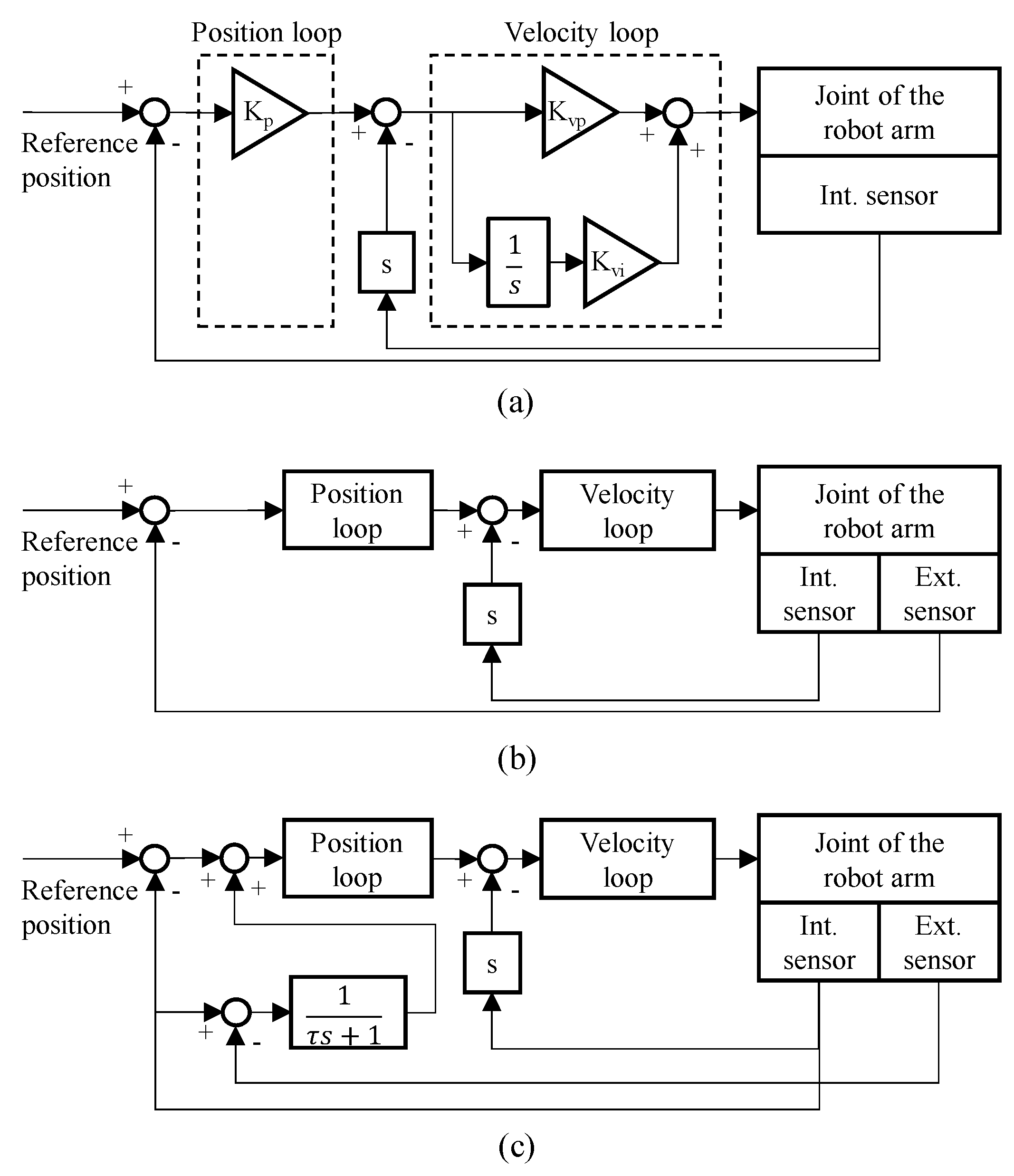
Figure 1a–c show block diagrams of a conventional a semi-closed loop, fully closed-loop, and the DPF control algorithm, respectively. A feedback controller comprises a proportional position loop and a proportional integral velocity loop, which is generally used for precision position control of the machine tool feed drives. The position loop generates the velocity command from the gap between the reference and actual positions measured by the position sensor. The velocity loop generates the current command from the gap between the velocity command and the actual velocity measured by the velocity sensor. A semi-closed loop is a typically used feedback control algorithm that refers to the position measured by an internal sensor and the velocity calculated from the measured position. A semi-closed loop cannot recognize and compensate for the position error caused by low stiffness. A fully closed loop is used to improve the positioning accuracy of a mechanical system containing both internal and external sensors. The aforementioned online compensation methods utilize also use a fully closed loop [10,11,12].
In the DPF controller, the input value of the position loop () is calculated as follows:
where , , and represent the reference position, the position measured by the internal sensor, and the position measured by the external sensor, respectively. A first-order transfer function with a time constant () is multiplied by the gap between the position measured by the internal and external sensors and added to the following error calculated by the position measured by the internal sensor. The transfer function reduces the noise and time skew caused by the external sensor and improves the stability. The DPF controller acts as a semi-closed loop when the time constant of the transfer function is set to a large value. Meanwhile, the DPF controller acts as a fully closed loop with a small time constant.
2.3. DOB-DPF Controller
The position error of the robot arm is compensated for by replacing the feedback position with an actual position measured by an external sensor. In this case, the control system becomes unstable when the external sensor includes noise. Although the feedback controller is configured based on an external sensor, an internal sensor is also required for velocity control. Therefore, time skew causes instability in the control performance when the sampling rates of the internal and external sensors differ [24]. In this regard, a DPF controller used for ultraprecision position control of the machine tool feed drive is utilized for online compensation of the position error.
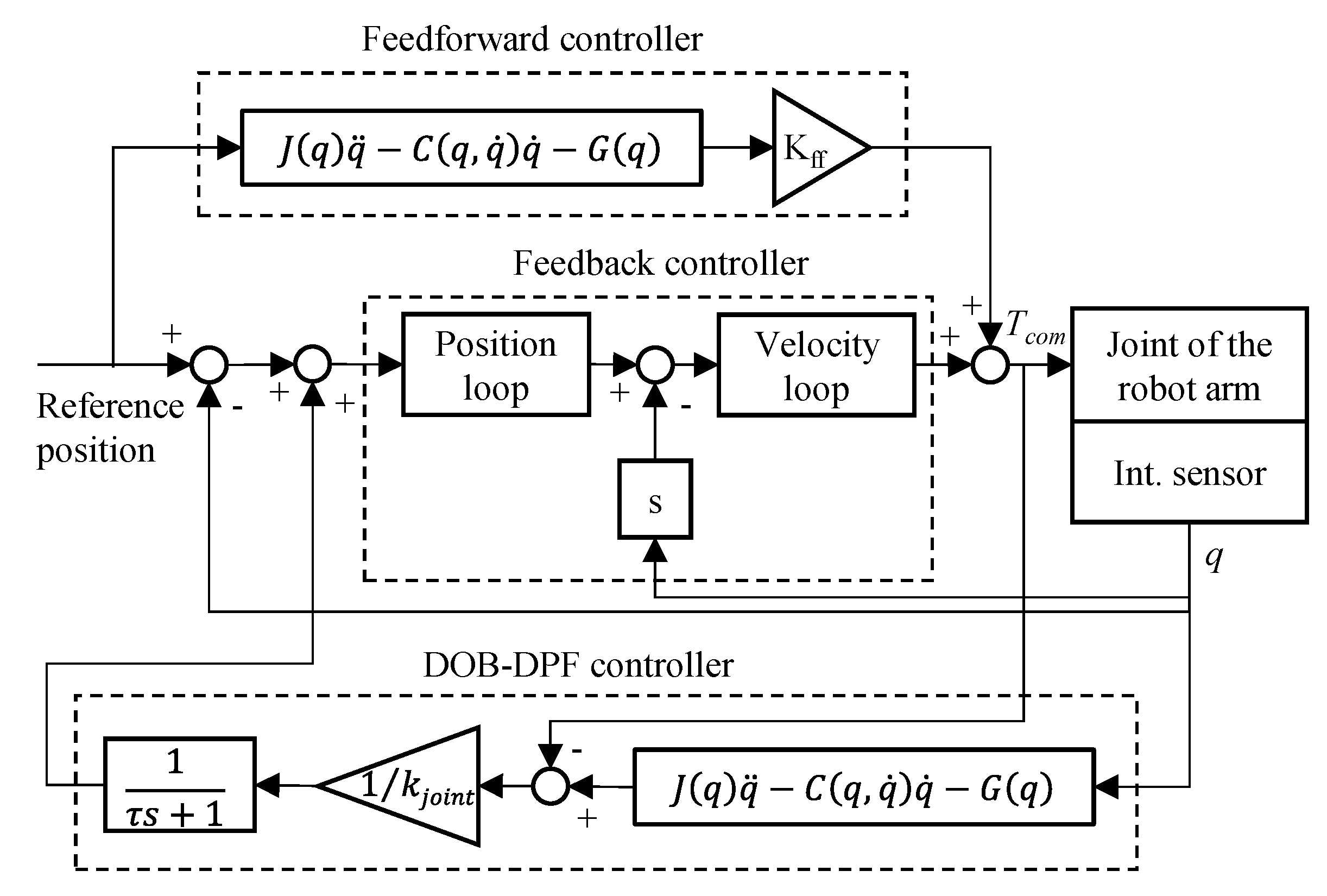
Generally, position errors with various frequencies are generated during operation. We aimed to design a position controller to compensate for the low-frequency position error caused by the weight or low-frequency component of the cutting force. High-frequency vibrations caused by the high-frequency components of the cutting force, such as the force variation between cutters in the milling process, are not considered in this study. Although the transfer function reduces the bandwidth of the DPF controller compared to a fully closed loop, the DPF controller can stably compensate for the low-frequency position error. In this study, a new DPF system was suggested. Conventional DPF systems have to be constructed with an external sensory system and an internal sensory system. However, the suggested control methods that use DOB do require the use of external sensors. Therefore, the reliability does not decrease as a result of the noise of sensors, with an effective decrease in construction costs. Figure 2 shows a block diagram of the DOB-DPF controller. The DOB-DPF controller comprises a feedback controller, feedforward controller, and the DOB-DPF algorithm. The feedback controller controls each joint to follow the target angle based on a proportional position loop and a proportional integral velocity loop. The feedforward controller compensates for the additional torque caused by the self-weight, as well as the Coriolis and centrifugal forces. The DOB-DPF algorithm integrates the DOB to calculate the actual position and the DPF controller to compensate for the angular deflection.
3. Design of a Five-DOF Robot Arm
3.1. Hardware Design
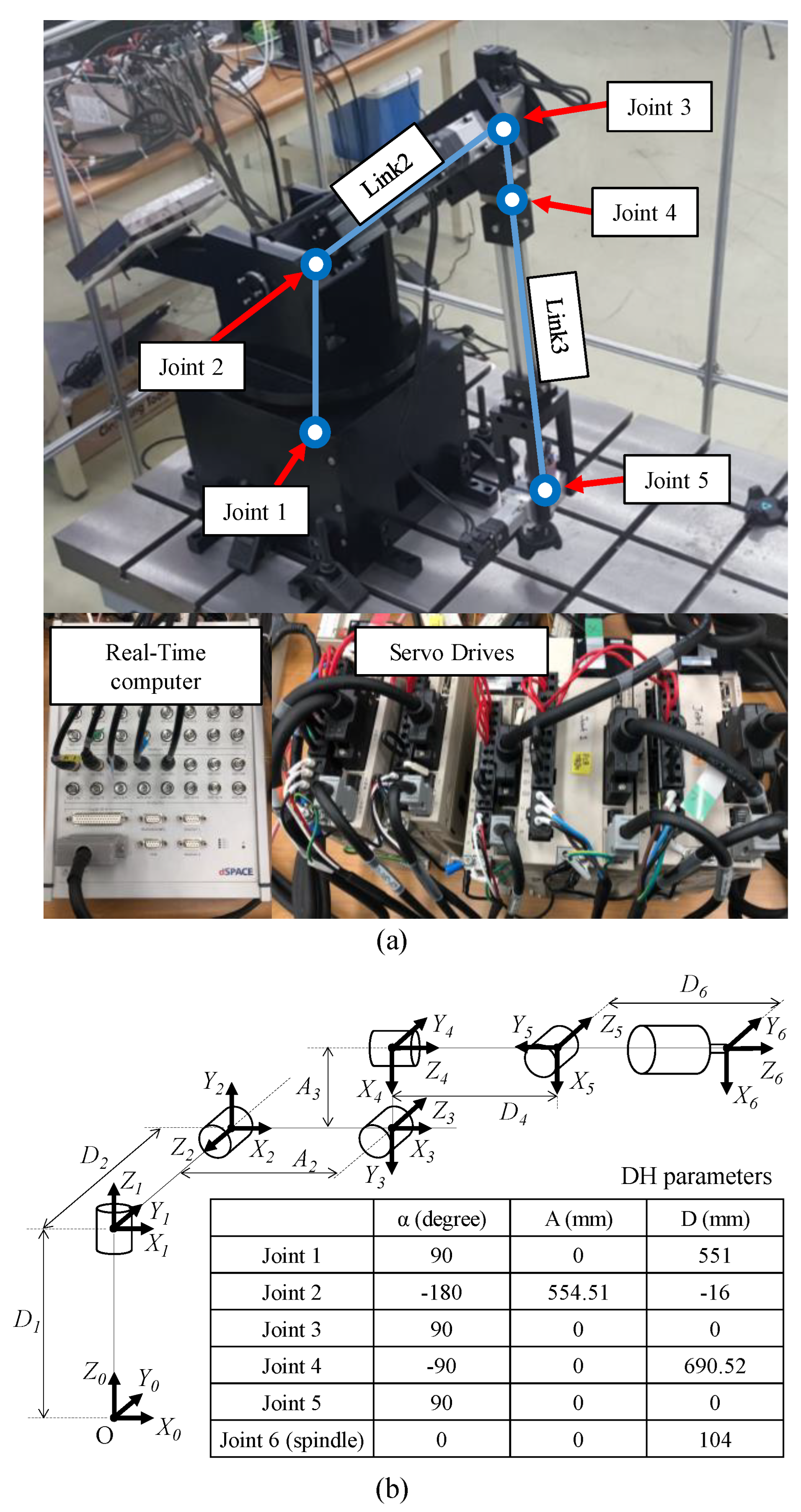
Figure 3a shows the experimental setup of the five-DOF robot arm. The payload of the robot arm was set to 50 N. The rated torque of the joint motors with reducers was designed based on the load torque applied to each joint. Joints 1 and 2 comprised a motor with a rated torque of 2.39 Nm (SGMAV-08A, Yaskawa) and a reducer with a gear ratio of 1/100 (PGX90-H100, ATG). Joint 3 comprised a motor with a rated torque of 1.27 Nm (SGMAV-04A, Yaskawa) and a reducer with a gear ratio of 1/100 (PGX62-H100, ATG). Joints 4 and 5, with relatively low loads, both had a rated torque of 0.159 Nm (SGMAV-04A, Yaskawa) and reduction gears (PGX44-H100, ATG) with a gear ratio of 1/100. Links 2 and 3 were each constructed with aluminum profiles measuring 40 mm × 80 mm and 40 mm × 40 mm, respectively. Figure 3b shows the Denavit–Hartenberg (DH) parameters, which represent the joint dimensions and relative angle of the robot processing system. Joints 1, 2, and 3 determine the position of the robot, whereas joints 4 and 5 determine the orientation of the robot. The designed five-DOF robot arm was installed on the surface of a plate table.
3.2. Controller Design
A numerical control kernel and a motion control unit were designed for the position control of the five-DOF robot arm. The numeric control kernel comprises an interpolator and a velocity profiler that generate the target profiles of the angular position of each joint from the user input, which contains the target position and orientation of the end effector. The interpolator calculates the target angular positions of the five joints to achieve the user input as follows.
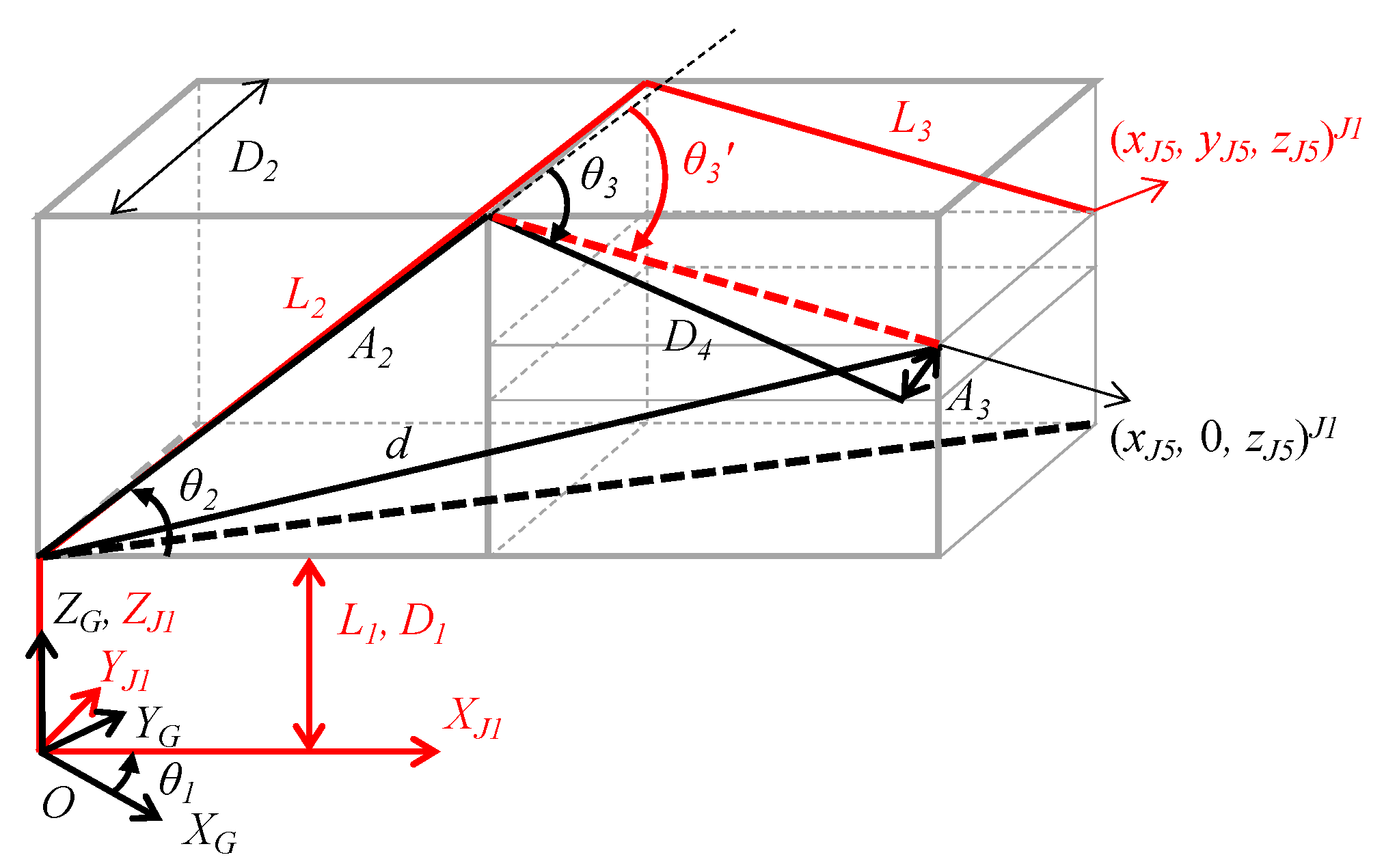
Figure 4 shows the postures of links 1 to 3 corresponding to the angles of joints 1 to 3 of the robot arm. (xJ5, yJ5, zJ5)J1 indicates the position of joint 5 in the J1 coordinate system, [XJ1, YJ1, ZJ1], which is rotated by θ1 in accordance with the global coordinate system [XG, YG, ZG]. The angular position of joint 1, () can be calculated from the target position of the end effector in the global coordinate, (, , )G, as follows:
(, , )J1 is derived from and the unit vector of the target orientation in the global coordinate (VTO = (xTO, yTO, zTO)G) using a rotational transformation matrix as follows:
The angular position of joint 2 () can be calculated as the sum of the angle between and and the angle between d and as follows:
where and are derived by (, 0, )J1 and the DH parameters, respectively. The angular position of joint 3 () is the sum of the angle between and , and , which denotes the angle between and .
The angular position of joint 4 () is the angle between the y-axis unit vector of the coordinate system of joint 1 (Y1) and the z-axis unit vector of the coordinate system of joint 5 (), which can be calculated as follows:
where is the x-axis unit vector of the coordinate system of joint 3, which is derived from to as follows:
The angular position of joint 5 () is the angle between and , which is calculated as follows:
The target profiles of the angular position can be derived by connecting the angular joints in the time domain. However, the acceleration and deceleration of the target profiles should be considered because large accelerations/decelerations increase the tracking error and instability of the robot arm. In this regard, a velocity profiler was designed to generate the target profiles of each joint, including the acceleration/deceleration section, as follows:
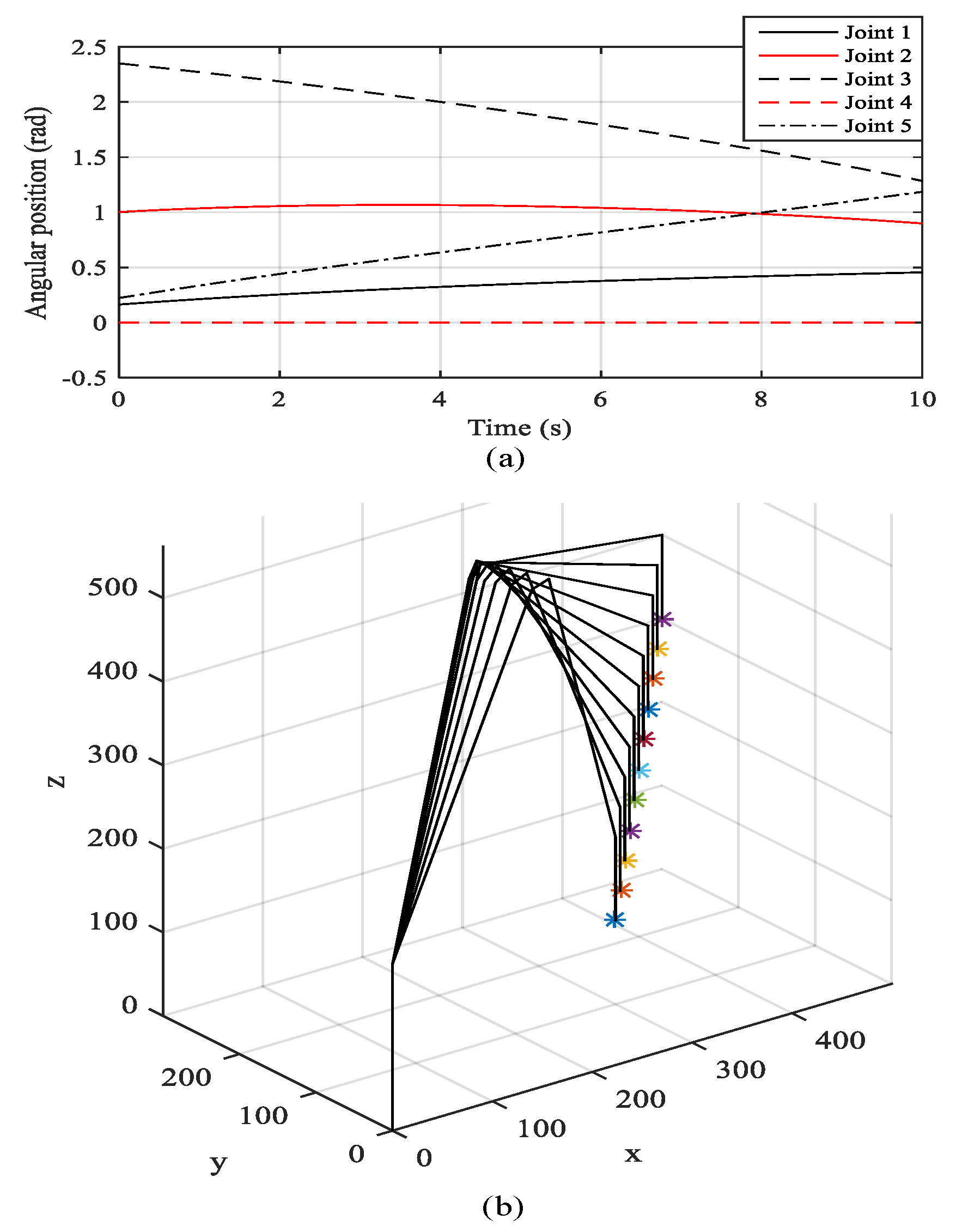
where and are the target angular velocities at the kth sampling before and after velocity profiling, respectively, and is the number of samples corresponding to the linear acceleration/deceleration section. Figure 5a shows the target angles of joints 1 to 5 generated in the numerical control kernel with respect to the initial position of (300 mm, 0 mm, 100 mm) to the target position of (500 mm, 200 mm, 300 mm), maintaining the target orientation as (0, 0, −1). Figure 5b shows the posture of the robot arm at every second calculated by forward kinematics based on the DH parameters and the target profiles of joints 1 to 5. The motion control unit is the DOB-DPF controller mentioned in the previous section, which controls the joint corresponding to the target angular profiles generated by the numeric control kernel.
3.3. Measurement of Stiffness
The angular deflection of each joint can be calculated by dividing the disturbance torque by the stiffness. The stiffness of the links was disregarded in this study because the stiffness of the joint is much lower than that of the links. The joint was controlled to keep the link parallel to the ground, and a capacitance sensor (CPL190, Lion precision) was installed above the end of the link. Subsequently, the increment in the gap between the capacitance sensor and the link was measured when a constant load was applied to the link. The increment of the stall torque of the joint in steady state was acquired by measuring the torque command of the joint motor. Finally, the stiffness of the joint was calculated by dividing the increment of the stall torque by that of the gap. The experiment was performed five times for each joint individually by increasing the applied load from 1 to 5 kg at intervals of 1 kg.
4. Evaluation of DOB-DPF Controller
4.1. Implementation of DOB-DPF Controller
The DOB-DPF controller was programmed using MATLAB and implemented on a robot arm using a real-time computer (Micro Lab Box, dSPACE). The sampling time was set to 0.001 s. The controller generated torque commands in the five joint motors as analog voltages in the range of −10 to 10 V. Each drive of the joint motor transferred the analog voltage to the target torque in a linear range of the rated torque and generated three phase-driving currents corresponding to the target torque. The encoder signal of each joint motor was transmitted to the digital input–output port of a real-time computer and decoded to the angular position. The angular position of the joint was derived by multiplying the gear ratio by the angular position of the joint motor and transmitted to the DOB-DPF controller.
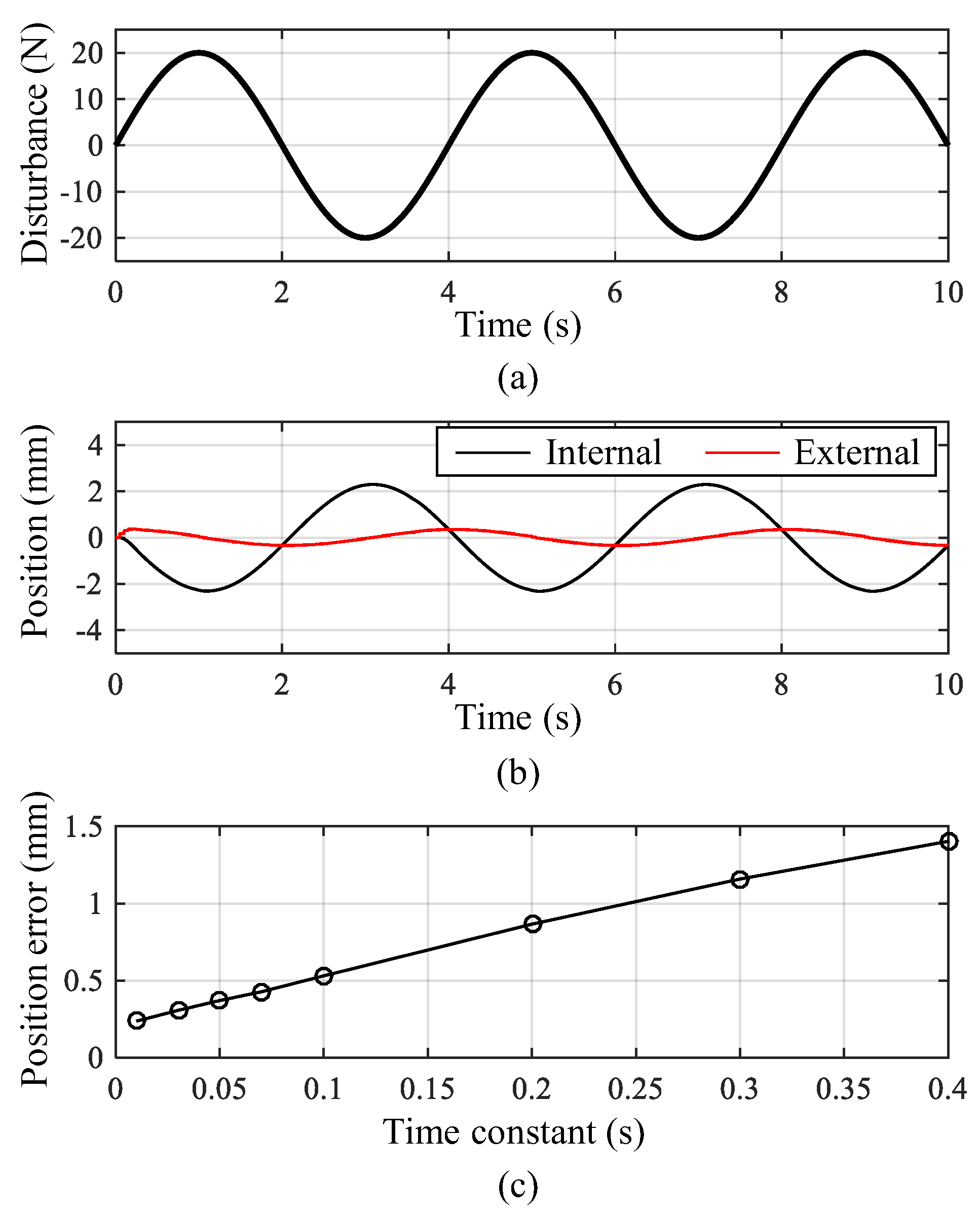
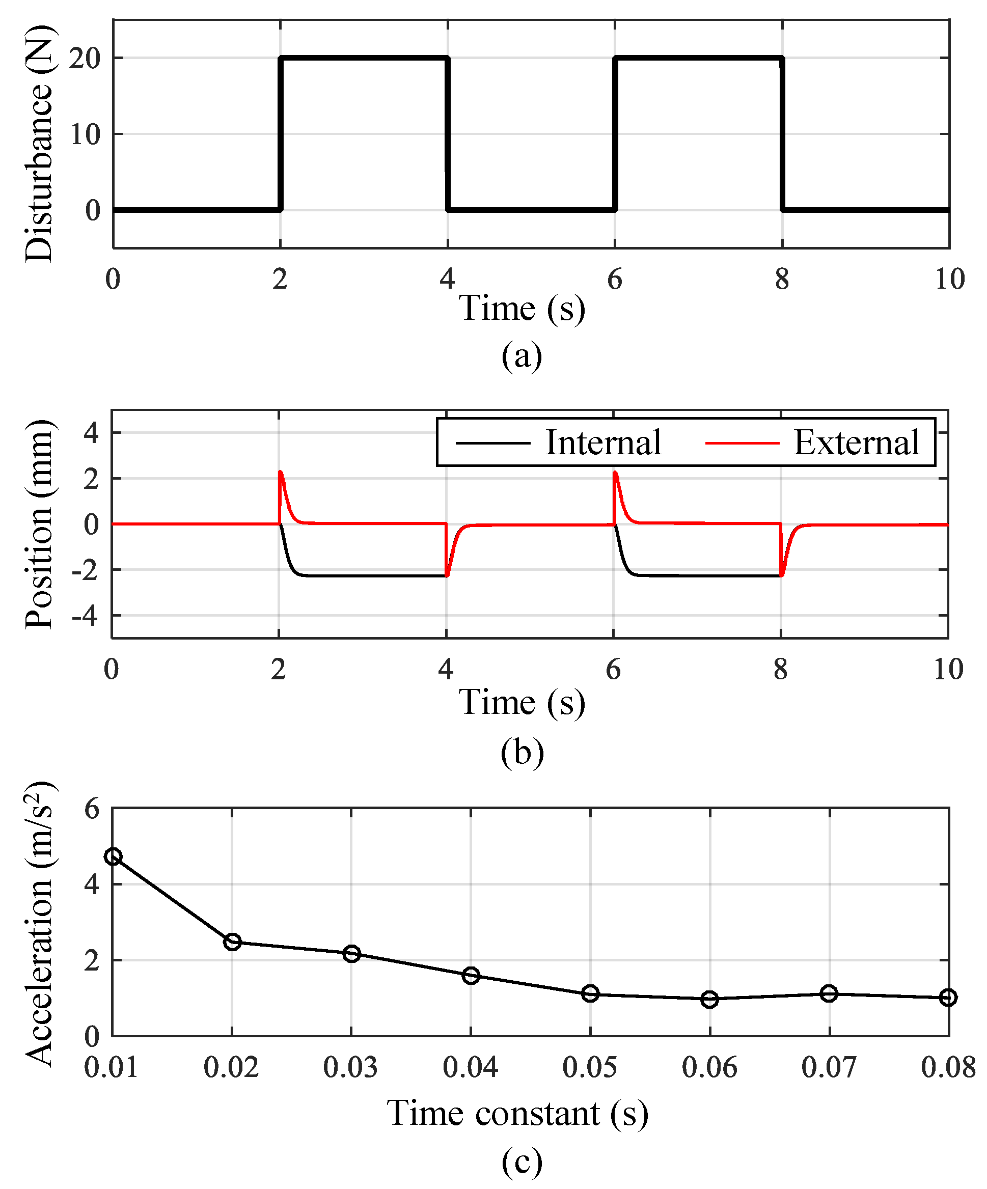
The performance of the DPF controller is determined by the time constant of the first-order transfer function. In this study, the optimal value of the time constant was derived based on simulations. The simulation model of the five-DOF robot arm was constructed based on the position control algorithm and kinematic model of the robot arm. Using the simulation model, periodic disturbances with an amplitude 20 N were applied to the end effector while the robot arm was controlled to maintain the current position. Figure 6b shows the position of the end effector recognized by internal and external position sensors when the sinusoidal disturbance shown in Figure 6a was applied to the end effector. The black line indicates the compensation motion of the robot arm, and the red line is the position error of the end effector. Figure 6c shows the peak values of the position errors with respect to the time constant of the DPF controller. The result shows that a lower time constant leads to better control performance because the position error increases proportionally to the time constant. Figure 7b shows the position of the end effector when the square wave disturbance shown in Figure 7a is applied. Figure 7c shows the peak values of the acceleration of the end effector with respect to the time constants. The result shows that a small time constant causes large acceleration, which reduces the position accuracy and stability. The acceleration reduced rapidly at low time constants and saturated at a time constant of 0.05 s. Consequently, the time constant of the DPF controller was set to 0.05 s to improve position accuracy and robustness to external disturbance.
4.2. External Position Sensing
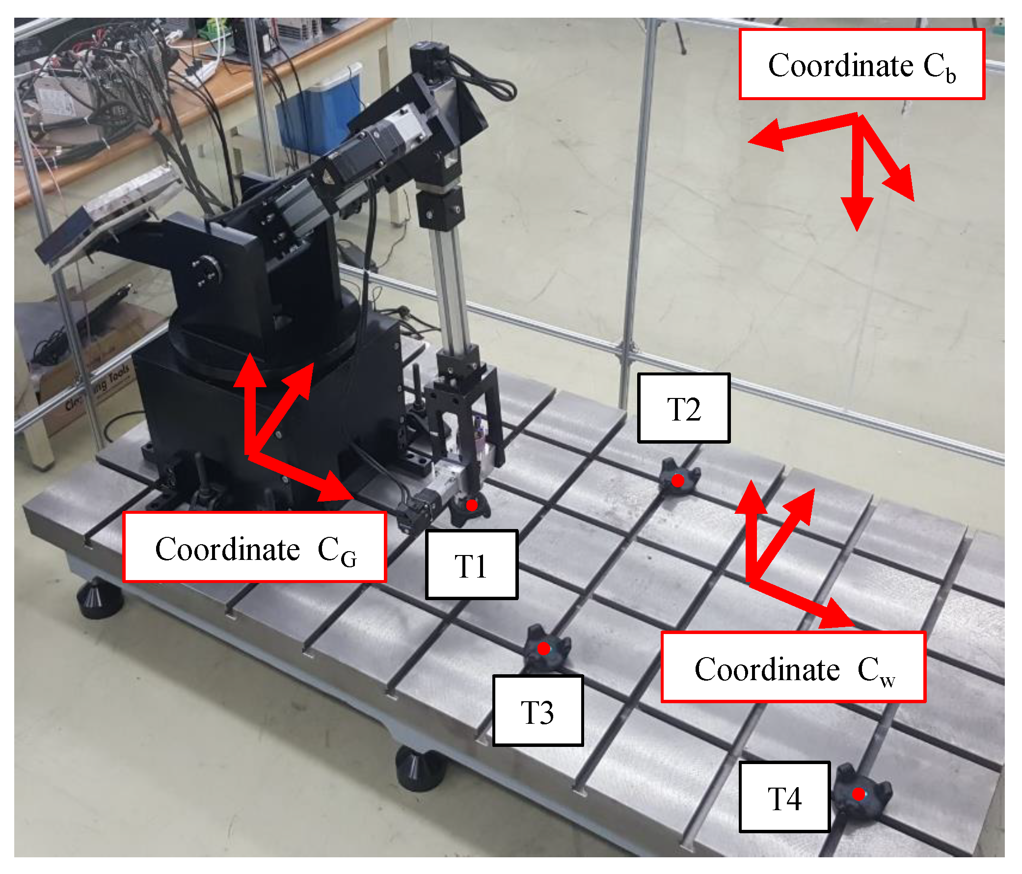
An external position sensor (Vive, HTC) was installed to measure the actual contour error of the end effector. Figure 8 shows the three Cartesian coordinates (Cb, Cw, and CG) used to calculate the actual position and contour error of the end effector. Cb is the coordinate of the Vive base station. The Vive acquires the three-dimensional position of the trackers with respect to the coordinates of the base station. The accuracy of the position measurement was 0.1 mm in our experimental setup. Cw and CG denote the coordinates of the worktable and robot arm, respectively. The actual position of the robot arm was measured by attaching a tracker (T1) to the end effector; subsequently, it was converted to the worktable coordinate using a homogeneous transformation matrix (HTM). The HTMs of the worktable and base station coordinates were derived from the unit direction vectors of the worktable coordinates measured by three trackers (T2, T3, and T4) installed on the worktable. The target position of the robot arm was generated in the worktable coordinate and converted to the robot arm coordinate for position control. The contour error was calculated based on the target and actual positions of the end effector in the worktable coordinate. The HTMs of the robot arm and worktable coordinates were derived from the unit direction vectors of the robot arm coordinates calculated by measuring the position of tracker T1 when the robot was linearly moving along the x, y, and z axes.
4.3. Evaluation Result
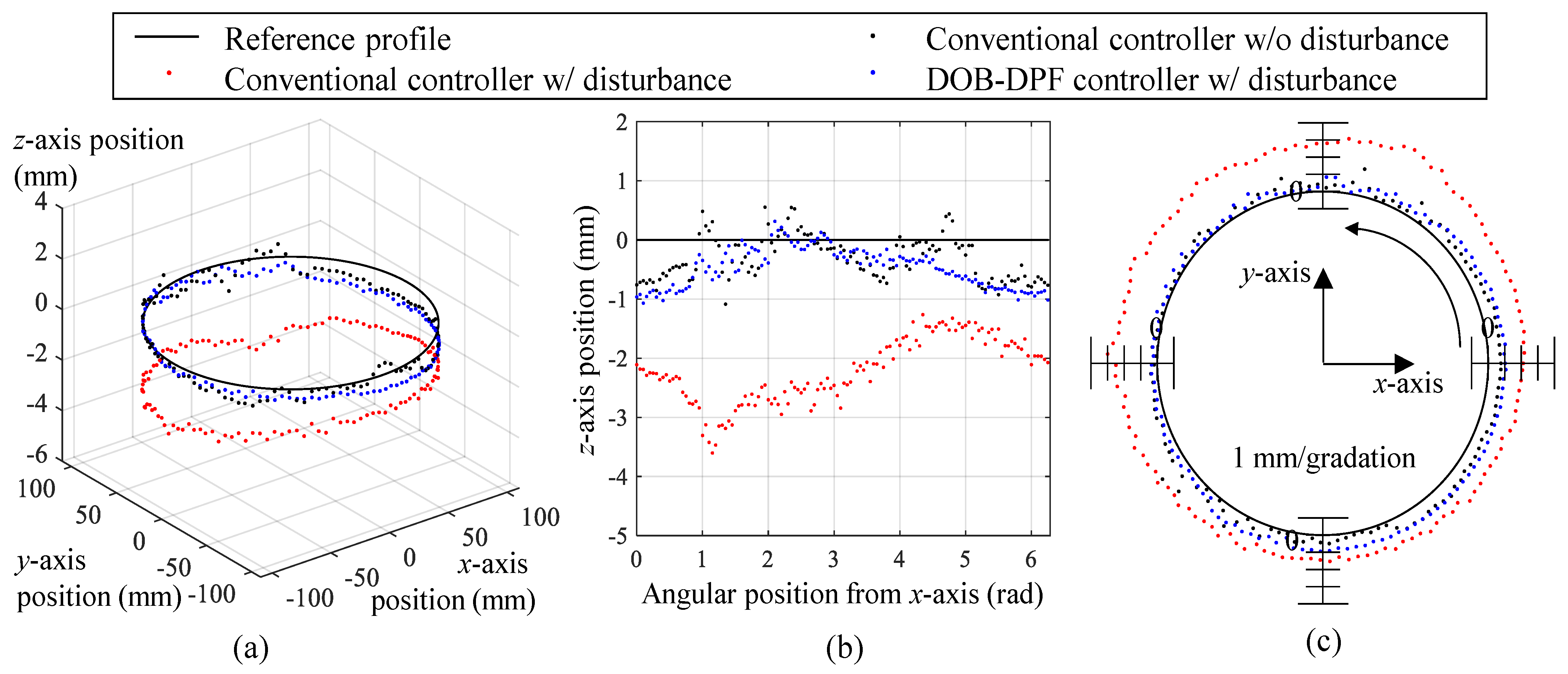
To evaluate the performance of the DOB-DPF controller, its contour errors were compared with those of a conventional controller comprising a feedback and feedforward module during circular interpolation. The trajectory of the robot arm was set to a circle with a radius of 100 mm in the xy plane of the worktable coordinate. Figure 9 compares the contouring performances of the two controllers before and after a constant weight of 2.2 kg was applied to the end effector. Figure 9a,b show that the position drop of the end effector caused by a significant weight reduction when the DOB-DPF controller is applied. The peak, root mean square (RMS), and standard deviation (STD) of the contour errors are listed in Table 1. The RMS value of the contour error of both the conventional and DOB-DPF controller was 0.59 mm when the external disturbance was zero. When a weight of 2.2 kg was applied to the end effector, the contour error of the conventional controller increased to 2.30 mm, whereas the contour error of the DOB-DPF controller increased to 0.71 mm. This result indicates that the contour error caused by the disturbance was compensated for by the DOB-DPF algorithm.
5. Conclusions
A DOB-DPF controller was proposed in this paper to compensate for the position error of a five-DOF robot caused by low stiffness. Angular deflections caused by external disturbances were calculated by the DOB without using external position sensors and compensated by the DPF control algorithm. A five-DOF robot arm and its position controller were constructed to verify the proposed DOF-DPF controller. Contour errors of the conventional position and proposed DOB-DPF controllers were compared during circular interpolation using an external position sensor. In the conventional position controller, the RMS value of the contour error increased from 0.59 to 2.30 mm after a 2.2 kg weight was applied to the end effector, whereas it increased from 0.59 to 0.71 mm in the proposed DOB-DPF controller.
Author Contributions
Conceptualization, W.L. and N.K.; methodology, W.L. and N.K.; software, N.K. and D.O.; validation, N.K. and J.-Y.O.; formal analysis, investigation, resources, data curation, writing—original draft preparation, and visualization, W.L. and N.K.; supervision, project administration, and funding acquisition, W.L. All authors have read and agreed to the published version of the manuscript.
Funding
This research was supported in part by the Technology Development Program for Smart Controller in Manufacturing Equipment (20012834, Development of Smart CNC Control System Technology for Manufacturing Equipment) funded by the Ministry of Trade, Industry & Energy (MOTIE, Korea) and in part by the Korea Institute of Machinery and Materials for the project “Development of Technology for Mobile Platform-based Machining System” (No. NK210B).
Conflicts of Interest
The authors declare no conflict of interest.
References
- Caro, S.; Dumas, C.; Garnier, S.; Furet, B. Workpiece placement optimization for machining operations with a KUKA KR270-2 robot. In Proceedings of the 2013 IEEE International Conference on Robotics and Automation, Karlsruhe, Germany, 6–10 May 2013; pp. 2921–2926. [Google Scholar]
- Wang, J.; Zhang, H.; Fuhlbrigge, T. Improving machining accuracy with robot deformation compensation. In Proceedings of the 2009 IEEE/RSJ International Conference on Intelligent Robots and Systems, St. Louis, MO, USA, 10–15 October 2009; pp. 3826–3831. [Google Scholar]
- Zhang, H.; Wang, J.; Zhang, G.; Gan, Z.; Pan, Z.; Cui, H.; Zhu, Z. Machining with flexible manipulator: Toward improving robotic machining performance. In Proceedings of the 2005 IEEE/ASME Interna-tional Conference on Advanced Intelligent Mechatronics, Monterey, CA, USA, 24–28 July 2005; pp. 1127–1132. [Google Scholar]
- Lee, W.; Lee, C.-Y.; Jeong, Y.H.; Min, B.-K. Distributed component friction model for precision control of a feed drive system. IEEE/ASME Trans. Mechatron. 2015, 20, 1966–1974. [Google Scholar] [CrossRef]
- Chen, Y.; Dong, F. Robot machining: Recent development and future research issues. Int. J. Adv. Manuf. Technol. 2012, 66, 1489–1497. [Google Scholar] [CrossRef] [Green Version]
- Belchior, J.; Guillo, M.; Courteille, E.; Maurine, P.; Leotoing, L.; Guines, D. Off-line compensation of the tool path deviations on robotic machining: Application to incremental sheet forming. Robot. Comput.-Integr. Manuf. 2013, 29, 58–69. [Google Scholar] [CrossRef] [Green Version]
- Munasinghe, S.R.; Nakamura, M.; Goto, S.; Kyura, N. Optimum contouring of industrial robot arms under assigned velocity and torque constraints. IEEE Trans. Syst. Man Cybern. 2001, 31, 159–167. [Google Scholar] [CrossRef]
- Olabi, A.; Damak, M.; Bearee, R.; Gibaru, O.; Leleu, S. Improving the accuracy of industrial robots by offline compensation of joints errors. In Proceedings of the 2012 IEEE International Conference on Industrial Technology, Athens, Greece, 19–21 March 2012; pp. 492–497. [Google Scholar]
- Schneider, U.; Drust, M.; Ansaloni, M.; Lehmann, C.; Pellic-ciari, M.; Leali, F.; Gunnink, J.W.; Verl, A. Improving robotic machining accuracy through experimental error investigation and modular compensation. Int. J. Adv. Manuf. Technol. 2016, 85, 3–15. [Google Scholar] [CrossRef]
- Xu, K.-J.; Li, C.; Zhu, Z.-N. Dynamic modeling and compensation of robot six-axis wrist force/torque sensor. IEEE Trans. Instrum. Meas. 2007, 56, 2094–2100. [Google Scholar] [CrossRef]
- Park, S.-K.; Lee, S.-H. Disturbance observer based robust control for industrial robots with flexible joints. In Proceedings of the 2007 International Conference on Control, Automation and Systems, Seoul, Republic of Korea, 17–20 October 2007. [Google Scholar]
- Moeller, C.; Schmidt, H.C.; Koch, P.; Boehlmann, C.; Kothe, S.; Wollnack, J.; Hintze, W. Real time pose control of an industrial robotic system for machining of large scale components in aerospace industry using laser tracker system. SAE Int. J. Aerosp. 2017, 2, 100–108. [Google Scholar] [CrossRef] [Green Version]
- Furuta, K.; Kosuge, K.; Mukai, N. Control of articulated robot arm with sensory feedback: Laser beam tracking system. IEEE Trans. Ind. Electron. 1988, 35, 31–39. [Google Scholar] [CrossRef]
- Park, J.; Chung, W. Design of a robust H∞ PID control for industrial manipulators. J. Dyn. Sys. Meas. Control 2000, 122, 803–812. [Google Scholar] [CrossRef]
- Zhang, G.; Li, J.; Jin, X.; Liu, C. Robust adaptive neural control for wing-sail-assisted vehicle via the multiport event-triggered approach. IEEE Trans. Cybern. 2021, 52, 12916–12928. [Google Scholar] [CrossRef] [PubMed]
- Zhang, G.; Li, J.; Liu, C.; Zhang, W. A robust fuzzy speed regulator for unmanned sailboat robot via the composite ILOS guidance. Nonlinear Dyn. 2022, 110, 2465–2480. [Google Scholar] [CrossRef]
- Li, J.; Zhang, G.; Shan, Q.; Zhang, W. A Novel Cooperative Design for USV-UAV Systems: 3D Mapping Guidance and Adaptive Fuzzy Control. IEEE Trans. Control. Netw. Syst. 2022. [Google Scholar] [CrossRef]
- Liu, S.; Wang, L.; Wang, X. Sensorless force estimation for industrial robots using disturbance observer and neural learning of friction approximation. Robot. Comput.-Integr. Manuf. 2021, 71, 102168. [Google Scholar] [CrossRef]
- Tong, S.; Min, X.; Li, Y. Observer-based adaptive fuzzy tracking control for strict-feedback nonlinear systems with unknown control gain functions. IEEE Trans. Cybern. 2020, 50, 3903–3913. [Google Scholar] [CrossRef] [PubMed]
- Cheng, X.; Tu, X.; Zhou, Y.; Zhou, R. Active disturbance rejection control of multi-joint industrial robots based on dynamic feedforward. Electronics 2019, 8, 591. [Google Scholar] [CrossRef] [Green Version]
- Yin, X.; Li, P. Enhancing trajectory tracking accuracy for industrial robot with robust adaptive control. Robot. Comput.-Integr. Manuf. 2018, 51, 97–102. [Google Scholar] [CrossRef]
- Mohammadi, A.; Tavakoli, M.; Marquez, H.J.; Hashemzadeh, F. Nonlinear disturbance observer design for robotic manipulators. Control. Eng. Pract. 2013, 21, 253–267. [Google Scholar] [CrossRef] [Green Version]
- Spong, M.W.; Hutchinson, S.; Vidyasagar, M. Robot Dynamics and Control, 2nd ed.; Wiley: Hoboken, NJ, USA, 2004; pp. 205–207. [Google Scholar]
- Kim, N.; Kim, H.; Lee, W. Hardware-in-the-loop simulation for estimation of position control performance of machine tool feed drive. Precis. Eng. 2019, 60, 587–593. [Google Scholar] [CrossRef]
Figure 1.
Block diagrams of (a) a conventional semi-closed loop, (b) fully closed loop, and (c) the DPF control algorithm.
Figure 1.
Block diagrams of (a) a conventional semi-closed loop, (b) fully closed loop, and (c) the DPF control algorithm.

Figure 2.
Block diagram of the DOB-DPF controller.

Figure 3.
Experimental setup of the five-DOF robot arm: (a) photo and (b) Denavit–Hartenberg (DH) parameters, which represent the joint dimensions and relative angle.
Figure 3.
Experimental setup of the five-DOF robot arm: (a) photo and (b) Denavit–Hartenberg (DH) parameters, which represent the joint dimensions and relative angle.

Figure 4.
Postures of links 1 to 3 according to the angles of joints 1 to 3 of the robot arm.

Figure 5.
Simulation result with respect to the initial position of (300 mm, 0 mm, 100 mm) to the target position of (500 mm, 200 mm, 300 mm), maintaining the target orientation as (0, 0, −1): (a) target angles of joints 1 to 5 generated in the numerical control kernel and (b) posture of the robot arm.

Figure 6.
Simulation result of the dual-position feedback controller with sinusoidal wave disturbance: (a) disturbance; (b) position of the end effector measured by internal and external position sensors; (c) peak position errors of the end effector with respect to the time constants of the dual-position feedback controller.

Figure 7.
Simulation result of the dual-position feedback controller with square wave disturbance: (a) disturbance; (b) position of the end effector measured by internal and external position sensors; (c) peak acceleration of the end effector with respect to the time constants of the dual-position feedback controller.

Figure 8.
Three Cartesian coordinates (Cb, Cw, and CG) and four trackers used to calculate the actual position and contour error of the end effector.
Figure 8.
Three Cartesian coordinates (Cb, Cw, and CG) and four trackers used to calculate the actual position and contour error of the end effector.

Figure 9.
Contouring performances of the conventional controller and the DOB-DPF controller before and after a constant weight of 2.2 kg was applied to the end effector: position of the end effector in (a) three-dimensional and (b) two-dimensional (XZ plane) graph and (c) contour errors.
Figure 9.
Contouring performances of the conventional controller and the DOB-DPF controller before and after a constant weight of 2.2 kg was applied to the end effector: position of the end effector in (a) three-dimensional and (b) two-dimensional (XZ plane) graph and (c) contour errors.


Table 1.
Peak, RMS, and STD of the contour errors.
| Control Method | Contour Error (mm) | ||
|---|---|---|---|
| Peak | RMS | STD | |
| Conventional controller w/o disturbance | 1.80 | 0.59 | 0.31 |
| Conventional controller w/ disturbance | 3.60 | 2.30 | 0.55 |
| DOB-DPF controller w/ disturbance | 1.08 | 0.71 | 0.32 |
Publisher’s Note: MDPI stays neutral with regard to jurisdictional claims in published maps and institutional affiliations. |
© 2022 by the authors. Licensee MDPI, Basel, Switzerland. This article is an open access article distributed under the terms and conditions of the Creative Commons Attribution (CC BY) license (https://creativecommons.org/licenses/by/4.0/).
Share and Cite
MDPI and ACS Style
Kim, N.; Oh, D.; Oh, J.-Y.; Lee, W. Disturbance-Observer-Based Dual-Position Feedback Controller for Precision Control of an Industrial Robot Arm. Actuators 2022, 11, 375. https://doi.org/10.3390/act11120375
AMA Style
Kim N, Oh D, Oh J-Y, Lee W. Disturbance-Observer-Based Dual-Position Feedback Controller for Precision Control of an Industrial Robot Arm. Actuators. 2022; 11(12):375. https://doi.org/10.3390/act11120375
Chicago/Turabian StyleKim, Namhyun, Daejin Oh, Jun-Young Oh, and Wonkyun Lee. 2022. "Disturbance-Observer-Based Dual-Position Feedback Controller for Precision Control of an Industrial Robot Arm" Actuators 11, no. 12: 375. https://doi.org/10.3390/act11120375
Note that from the first issue of 2016, this journal uses article numbers instead of page numbers. See further details here.