Article

Design of Eco-Efficient Body Parts for Electric Vehicles Considering Life Cycle Environmental Information

1
Group Innovation, Volkswagen AG, Berliner Ring 2, 38440 Wolfsburg, Germany
2
Open Hybrid LabFactory e.V., Hermann-Münch-Straße 2, 38440 Wolfsburg, Germany
3
Institute of Machine Tools and Production Technology, Chair of Sustainable Manufacturing and Life Cycle Engineering, Technische Universität Braunschweig, Langer Kamp 19b, 38106 Braunschweig, Germany
4
Institut für Konstruktionstechnik, Technische Universität Braunschweig, Langer Kamp 8, 38106 Braunschweig, Germany
*
Author to whom correspondence should be addressed.
Sustainability 2020, 12(14), 5838; https://doi.org/10.3390/su12145838
Submission received: 15 May 2020 / Revised: 24 June 2020 / Accepted: 27 June 2020 / Published: 20 July 2020

Abstract

:
The reduction of greenhouse gas (GHG) emissions over the entire life cycle of vehicles has become part of the strategic objectives in automotive industry. In this regard, the design of future body parts should be carried out based on information of life cycle GHG emissions. The substitution of steel towards lightweight materials is a major trend, with the industry undergoing a fundamental shift towards the introduction of electric vehicles (EV). The present research aims to support the conceptual design of body parts with a combined perspective on mechanical performance and life cycle GHG emissions. Particular attention is paid to the fact that the GHG impact of EV in the use phase depends on vehicle-specific factors that may not be specified at the conceptual design stage of components, such as the market-specific electricity mix used for vehicle charging. A methodology is proposed that combines a simplified numerical design of concept alternatives and an analytic approach estimating life cycle GHG emissions. It is applied to a case study in body part design based on a set of principal geometries and load cases, a range of materials (aluminum, glass and carbon fiber reinforced plastics (GFRP, CFRP) as substitution to a steel reference) and different use stage scenarios of EV. A new engineering chart was developed, which helps design engineers to compare life cycle GHG emissions of lightweight material concepts to the reference. For body shells, the replacement of the steel reference with aluminum or GFRP shows reduced lifecycle GHG emissions for most use phase scenarios. This holds as well for structural parts being designed on torsional stiffness. For structural parts designed on tension/compression or bending stiffness CFRP designs show lowest lifecycle GHG emissions. In all cases, a high share of renewable electricity mix and a short lifetime pose the steel reference in favor. It is argued that a further elaboration of the approach could substantially increase transparency between design choices and life cycle GHG emissions.

1. Introduction

The design of future vehicle generations and their constituting parts is driven by major transitions, e.g., electrification of drivetrains, prolonged lifetime driving distances or adapted driving profiles in Mobility-as-a-Service (MaaS) business models [1]. Within societal, politic and industrial discussion, the mitigation of negative environmental impacts, especially considering climate change and the reduction of greenhouse gas emissions (GHG), have been identified as prevalent global challenge. This is also acknowledged by automotive original equipment manufacturers (OEM), e.g., Volkswagen, stating that new vehicle generations must contribute to a reduction of life cycle environmental impacts [2]. Therefore, an increased demand for robust and comprehensive Life Cycle Engineering (LCE) approaches arises. According to Hauschild et al., LCE describes “sustainability-oriented product development activities […]. The methods and tools […] must support reducing the total environmental impact associated with technology change and volume increase from one product generation to another” [3]. The Life Cycle Assessment (LCA) methodology serves as a means to determine environmental impacts over the entire life cycle, including upstream processes, manufacturing, use and end-of-life [3].
Lightweight design approaches leveraging material substitution became a major innovation strategy for vehicle body parts. This includes shifts from conventional steel designs to lightweight metals as well as the introduction of glass and carbon fiber reinforced plastics (GFRP and CFRP). Lightweight materials typically show a higher embodied energy and thus associated GHG emissions per kg material in comparison to steel [4]. As a result, even if a weight reduction is realized, vehicles leaving the factory gate could carry an additional environmental burden that needs to be compensated within the vehicle use stage and/or adapted end-of-life routes [5,6].
The widening of the material scope also results in a large variety of competing design alternatives [7,8]. LCE should assist in quickly evaluating potential environmental impacts of all alternatives. However, the conceptual design stage of body parts is subject to unknown parameters regarding its respective life cycle, that needs to be reflected in environmental assessment [9,10]. The results should be fed back to an early stage of conceptual design. Furthermore, a coupling between engineering models, LCA models and integrated interpretations facilitates interdisciplinary knowledge between domain engineers and experts in environmental assessment [11,12].
The present research aims at contributing to the field in three major aspects. Firstly, an analytical method should be developed that links the conceptual design of lightweight body parts with LCA-based assessments of potential GHG impacts. Secondly, the method should be applied to a simplified but representative design scenarios to understand the range of possible environmental impacts and thus the underlying demand for LCE. Thirdly, the results should be combined in engineering diagrams that facilitate to estimate the influence of design decisions on life cycle GHG impacts.
To achieve the desired contributions, Section 2 presents the background of the present study. Section 3 reviews the state of research with respect to methods and tools at the interface of conceptual design and environmental evaluation. On that basis, Section 4 outlines the methodology developed in this study. Section 5 describes a case study addressing a body part of an innovative vehicle concept. Section 5 presents the conclusions and implications for further research.

2. Background

Body parts are functional elements of vehicles that enable mobility of passengers or goods. Their conceptual design takes place upstream to the development process of a series production vehicle [13]. Thereby, body part concepts are designed concurrently with other body parts or even other vehicle sub-systems, e.g., drivetrains or interior components [14,15]. Those sub-systems then can be applied to different vehicles with specific life cycle characteristics. Environmental impacts of body parts can be directly associated to the part design itself as well as surrounding technical systems within or outside the direct influence of OEM engineering activities, the so-called fore and background systems [5]. Figure 1 describes the theoretical framework for the present research that combines foundations on conceptual design of lightweight body parts and LCA-based assessments as well as their interplay. It is based on the nested LCA-based LCE framework for lightweight structures presented by Herrmann et al. [5] as well as an earlier description of a concurrent design and LCE of lightweight body parts [9]. The inner part describes the technosphere system in the focus of the study, namely the conceptual design of lightweight body parts (grey). The outer shells (blue) represent the steps of LCA according to ISO 14040. Thereby, the Life Cycle Inventory (LCI) subsumes all exchanges of material and energy as well as emissions within the technosphere as well as to the biosphere. On that basis, environmental impacts are determined within Life Cycle Impact Assessment (LCIA), followed by an interpretation of results.
Inner and outer shell activities are linked to engineering domains. The interplay between those in automotive industry has been explored for many years [16]. Despite successful examples for developing body parts with low environmental impacts exist, there is indication that the engineering with LCA-based insights is still insufficient in practice. A survey within the German automotive industry in the context of lightweight body parts in 2018 showed that two thirds of companies did not use LCA as a standard tool. Thereby, a high data collection effort, the development of an appropriate methodology and the difficult use of the results in decision making contexts were identified as obstacles [1].
When evaluating environmental impacts of lightweight structures for electric vehicles, previous research identified key parameters in the context of the life cycle, which are shown in Figure 1 (blue). The eLCAr guidelines for the LCA of electric vehicles serve as a foundation for defining the studied system and the identification of those key parameters [15]. The guidelines state that when assessing new EV body concepts, the design and production of the lightweight chassis should be regarded as part of the foreground system, while upstream or downstream processes are part of the background system. Regarding the assessment of environmental impacts of EV body parts, the eLCAr guidelines as well as a review carried out by Cerdas et al., point out a number of key parameters. Besides factors originating from vehicle design, regional and use stage specific factors as well as their interdependencies should be considered in a systematic approach. The main factors are the materials and mass differences of a body part compared to a reference, vehicle-specific characteristics such as use stage energy savings due to reduced weight, the vehicle use pattern and the electricity mix used for vehicle charging [6,15,17]. Cox et al. underline this through quantifying the drivers on climate change impacts of future EV in a multi-criteria approach. Lifetime driving distance, glider mass and the electricity mix used for vehicle charging are identified as main influencing factors with respect to expected lifecycle GHG emissions [10].
Within upstream processes, material compositions and demand originate from engineering processes performed in conceptual design, that result in statements on expected component mass and materials. Combined with information on upstream processing technologies and shares of secondary materials, they build the basis for evaluating environmental impacts. Prominent examples are the alloying of metals, different fiber reinforcements for FRP or the production of metals from primary or secondary sources [4]. Within the manufacturing stage, the selection of process chains is as well linked to the design [9]. Energy and material demands within the manufacturing can be determined based on design information. Schönemann et al. provide an example of an energy-oriented simulation, whereas Broch discusses the prognosis of yield losses based on design information [18,19]. Egede pointed out the importance of considering regional differences in electricity mixes when evaluating life cycle environmental impacts of body parts. Higher shares of renewable electricity sources decrease the potential for reducing life cycle greenhouse gas emissions through lighter body parts [6]. At the end-of-life stage, the eLCAr guidelines propose to consider the analysis of shredding, separation, treatment as well as intended material recycling processes [15]. This approach is also well followed by Delogu et al. who assess environmental impacts for a larger set of EV components combining metals and fiber-reinforced plastics. Within end-of-life, state-of-the-art recycling processes are compared to a future scenario. One major finding is that an efficient material recycling could significantly reduce the environmental impact of the regarded components [20].

3. Literature Review

Resulting from the presented background, three major tasks have to be managed in order to derive conceptual designs of body parts with low life cycle environmental impacts.
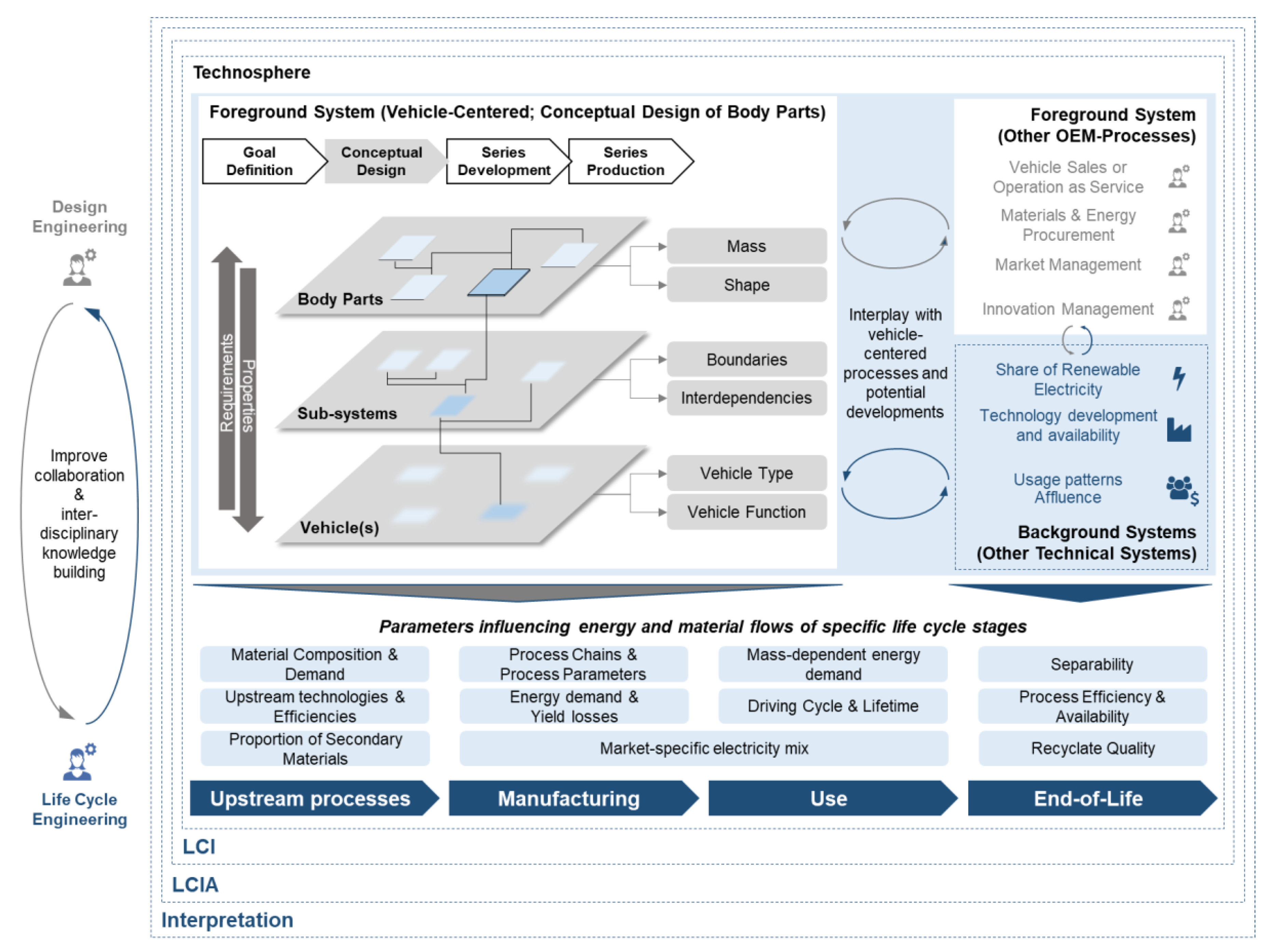
  • Firstly, body parts have to be designed for different materials and manufacturing concepts with regard to the fulfillment of mechanical properties. With respect to the early conceptual design phase, the method input should rely on simplified product models. Typically, no CAD (Computer Aided Design) or FE (Finite Element) models exist as a basis to generate design options that incorporate new materials or change the design of components. At the same time, available installation space should be considered as a boundary condition, as packaging is a major challenge in vehicle development. In order to qualify a broad solution, methods should enable a comparison of different material alternatives.
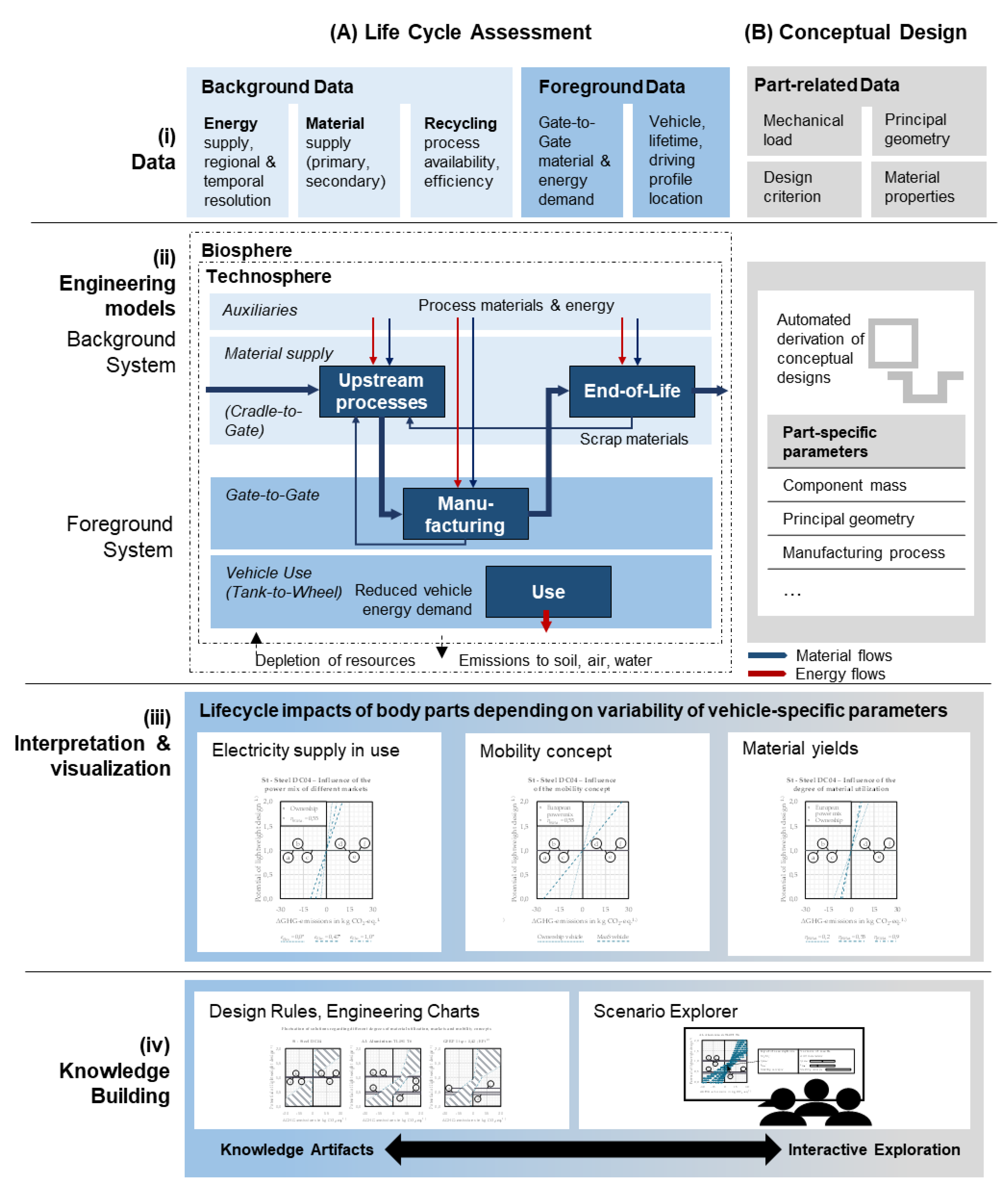
  • Secondly, life cycle environmental impacts need to be determined for the derived conceptual designs. In line with conceptual design, method inputs should rely on descriptions of the component life cycle regarding its fore- and background system. Based on those inputs, different scenarios and associated variabilities within the vehicle life cycle need to be determined. This includes technological, temporal and spatial variabilities. For this reason, a model-based approach that enables to vary key parameters needs to be followed.
  • Thirdly, an interpretation and prioritization of concept alternatives should be enabled. This implies that quantified results can be derived from both models and integrated in a joint interpretation of both. The interpretation should be tailored for engineering designers and related decision-makers as the major target audience.
A number of past studies addressed the interface of conceptual design and environmental assessment. To specify the research gap, those studies are analyzed with respect to their major characteristics. Only studies with a focus on automotive components (passenger cars, light duty vehicles) were considered, as models and derived decisions should specifically address the presented interface. Also, studies that solely focused on Life Cycle Assessment of vehicle components have been excluded from the review, as those do not enable a direct application of LCA results in engineering tasks. Table 1 provides an overview of identified approaches.
The studies presented within Table 1 originate from different research streams. Egede provides an LCA-based methodology that elaborates the interplay of life cycle environmental impacts between lightweight design options and different use phase scenarios of electric vehicles. It could be applied for design comparisons but does not assist in generating the design itself [6]. Ermolaeva et al., Grujicic et al., Poulikidou et al. as well as Mayyas et al. start from a material selection perspective and aim at incorporating component design and sustainability aspects into this engineering task [21,22,23,24,25]. Kaspar et al. and Stoffels et al. aim at developing a holistic design methodology that enables the application of new materials as well as cross-component aspects including redesign [26,27,28]. Delogu et al. and Dattilo et al. start from a Life Cycle Assessment perspective and aim at assisting the development of a set of innovative automotive components [29,30,31]. Luk et al. contribute to the field by studying which variables affect life cycle GHG emission impacts of vehicle lightweighting. While insights on GHG drivers on a vehicle level are presented, the method does not support the transfer of the findings from conceptual design on a body part level [32,33]. From the state of research, different findings can be drawn as an input for further research. Those are listed in Table 2.
Based on the identified research demands, a methodology to address those challenges is proposed. Section 4 first describes the overall methodology and subsequently details single methodological steps.

4. Design of Eco-Efficient Body Parts Considering Life Cycle Environmental Information
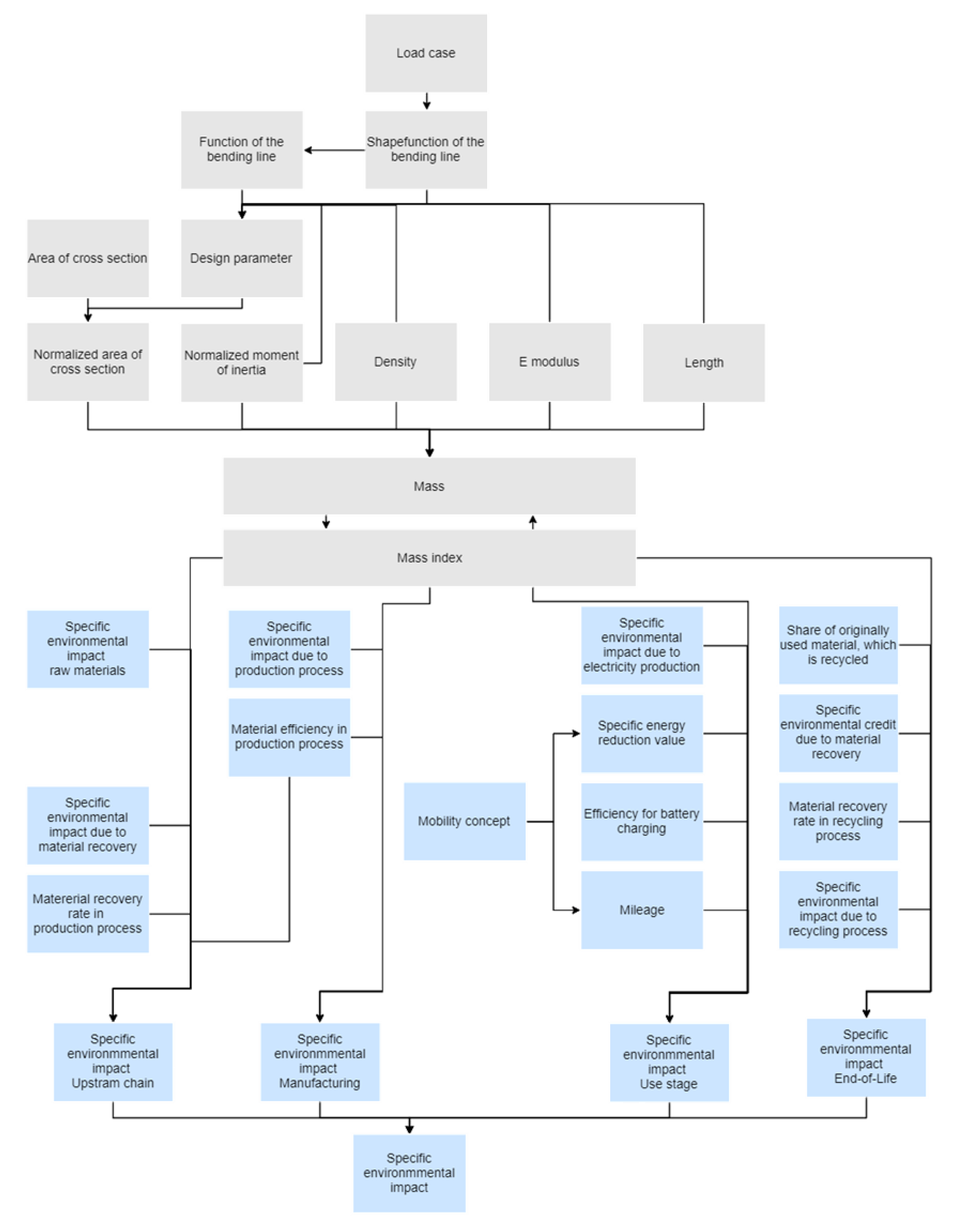
Figure 2 summarizes the overall methodology proposed to bridge the gap between body part design and LCA-based LCE applied within the present research. The methodology is organized in two pillars (A Life Cycle Assessment, B Conceptual Design) and four levels (i Data, ii Engineering models, iii Interpretation and visualization, iv Knowledge building). The pillars are associated to the involved disciplines, i.e., environmental impact evaluation based on Life Cycle Assessment (LCA) and conceptual design, whereas the levels are organized around a Visual Analytics-based LCE workflow as introduced by Kaluza et al. [12]. This also includes a perspective on applied input data, e.g., background data like environmental impacts in material and energy supply, foreground data like the production and use scenario of the vehicle as well as part-related data regarding the part geometry, mechanical loading and design criteria.
The second level of the methodology targets the derivation of engineering models for conceptual design and environmental assessment. Due to the early concept phase, design alternatives need to be generated based on requirements for mechanical loads, design criteria, material properties and principal geometries. Therefore, analytical design methods are applied to determine part geometries, component masses and potential manufacturing routes. The evaluation of environmental impacts is based on the assessment of energy and material flows of the observed product system over its life cycle (upstream processes, production, use, end-of-life) and the associated depletion of resources as well as emissions. Due to its application for evaluating early stage technologies, the Life Cycle Inventory (LCI) needs to rely on predefined models and account for parameter variability. Therefore, analytic relations for the quantification of energy and resource flows within the different life cycle stages are derived. This enables a flexible application for different body part concepts as well as their life cycles (geometry, material, manufacturing concept, use case of the vehicle).
Level three of the methodology aims at the interpretation of the derived findings. This includes the interpretation of both model results and associated variabilities from the perspective of conceptual design. Engineering charts are proposed that enable the identification of the sensitivities of life cycle environmental impacts against potential mass reductions for specific substitution cases. In this way, the influence of specific life cycle parameters (e.g., the electricity supply in use, the mobility concept of the vehicle or the material yield of the body part under investigation) on life cycle environmental impacts can be determined for specific conceptual designs.
A combination of all insights from interpretation is targeted within the knowledge building phase in level four of the methodology. Within the current research, knowledge artifacts are redacted twofold. First, a combined engineering chart enables accounting for variability of life cycle parameters and can inform designers if a concept alternative can be beneficial regarding its life cycle environmental impacts compared to a reference design. Due to the aforementioned variability, those charts do not provide a single-point decision support but enable the understanding of the bandwidth of environmental impacts associated to a certain design option. As those engineering charts represent static snapshots of the combined models and represent minimum and maximum assumptions with regard to the entire vehicle life cycle, an interactive exploration is provided as an additional representation of engineering knowledge. In this way, engineers and decision makers can set assumptions in line with specific conditions of the engineering project, e.g., traditional vehicle vs. MaaS. Thus, a then limited bandwidth of life cycle environmental impacts enables a more focused prioritization of concept alternatives and thus a direct added value for specific engineering processes.
Key elements, calculations and assumptions for the presented methodology as well as the derived insights are presented in the following.

4.1. Design Method

The derivation of mass indices can provide a first step for the concept development of body parts of different materials. With the help of these indices, an estimation of the body part mass under consideration of different material concepts is possible [35]. The derivation of mass indices requires information regarding the part geometry (e.g., a simplified and analytic predictable geometric abstraction of the real body part geometry), the mechanical load (e.g., axial, bending or torsional load case) and design criteria (e.g., design on stiffness or strength) of the body part, Table 3.
These indices are currently limited to parts with rectangular cross sections as well as some special cases like circular ring cross sections. For example, Equation (1) shows the mass index for the comparison of different material concepts of body parts with a rectangular cross section, which are designed on the same bending stiffness. Further mass indices for different kinds of loading and design criteria can be found in Weißbach et al. 2018 [20].
M ρ E 3
Analogous to the approach of Weißbach et al., mass indices for parts with arbitrary composed profile cross sections can be derived. For example, the mass index for a profile, e.g., a U-profile that should be designed on bending stiffness, can be derived by the following approach. In this context, Figure 3 shows the assumed simplifications regarding the load of the part, e.g., a line load qz(x) in z-direction. Figure 3 shows an idealized cross section of the U-profile with the geometry parameters height h, breadth b and thickness t.
Starting with the conventional bending line w(x), Equation (2), and simplifications shown in Equation (3) to (5), the bending line can be dissolved to the design parameter z, Equation (6). The design parameter z specifies which geometry parameter xj is adapted for the achievement of an equivalent bending stiffness EIy by using different material concepts. In this context, E represents the E-modulus and Iy the moment of inertia. The parameters x1, x2, …, xi define the geometry parameters—e.g., the height h, the breadth b and the thickness t for a U-profile. α1, α2, …, αi−1 describe the relation parameters, which quantify the relation between the geometry parameter to the design parameter. The parameter q0 × K(x) describes loading and the boundary conditions of the simplified profile.
w ( x ) = q 0 × K ( x ) E I y
w i t h   I y ( x 1 , , x i ) = z 4 × i y ( α 1 , , α i 1 )
a n d   z = x l   w i t h   l = 1 ,   2 ,     o r   i
a n d   α k = x j z   w i t h   k = 1 , 2 , , i 1   ;   j = 1 ,   2 ,   , i   a n d   j l
w ( x ) = q 0 × K ( x ) E × z 4 × i y ( α 1 , , α i 1 )     z = q 0 × K ( x ) E × w ( x ) × i y ( α 1 , , α i 1 ) 4
Furthermore, the mass of the profile m can be calculated according to Equation (7). Equation (8) shows assumed simplifications. In this context, ρ represents the density of the material, A represents the area of the profile. By inserting the design parameter z (Equation (6)) into mass calculation (Equation (8)), the mass with regard to the mechanical properties of the profile can be calculated (Equation (9)). Thus, the mass index M can be derived (Equation (10)). This approach can be applied to different kinds of loading and design criteria.
m = ρ l A ( x 1 , , x i ) = ρ l × z 2 × a   ( α 1 , , α i 1 )
w i t h   a   ( α 1 , , α i 1 ) = A   ( x 1 , , x i ) z 2
m = q 0 × K ( x ) × l 2 w ( x )   2 × ρ × a   ( α 1 , , α i 1 ) E i y ( α 1 , , α i 1 ) 2
M ρ × a   ( α 1 , , α i 1 ) E × i y   ( α 1 , , α i 1 ) 2
With this approach, the lightweight potential through application of alternative material concepts can be estimated. Therefore, the ratio between two mass indices M2 and M1 has to be calculated, Equation (11). M1 describes the mass indices of the reference material, M2 the mass indices with the alternative material.
M 2 M 1 = ρ 2 × a 2   ( α 2 , 1 , , α 2 , i 1 ) E 2 × i y , 2   ( α 2 , 1 , , α 2 , i 1 ) 2 ρ 1 × a 1   ( α 1 , 1 , , α 1 , i 1 ) E 1 × i y , 1   ( α 1 , 1 , , α 1 , i 1 ) 2
The relation parameters α1,1, α1,2, …, α1,i−1 are known through the reference concept. For thin-walled profile geometries and by adaption of the sheet thickness t for the achievement of an equivalent bending stiffness, Equation (12) provides an approach for the calculation of the relation parameters α2,1, α2,2, …, α2,i−1. For thick-walled profiles, Equation (13) can be applied. This equation describes an iterative approach. As start value for α2,1, α2,2, …, α2,i−1, Equation (12) can be applied.
α 2 , i 1 = α 1 , i 1 × E 2 E 1
α 2 , i 1 = α 1 , i 1 × ρ 2 ρ 1 × a 2 ( α 2 , 1 , , α 2 , i 1 ) a 1 ( α 1 , 1 , , α 1 , i 1 ) × M 1 ( α 1 , 1 , , α 1 , i 1 ) M 2 ( α 2 , 1 , , α 2 , i 1 )
This approach is restricted to the variation of one geometric parameter at a time—in most cases the sheet thickness t. However, higher lightweight potentials might be achieved by alternative material concepts that adapt the whole geometry in a defined design space.

4.2. Environmental Assessment

The assessment of the environmental effect results follows the LCA methodology. Its goal is to determine life cycle environmental impacts of automotive body part concepts compared to reference designs. Therefore, the entire component life cycle will be considered. Figure 4 details the life cycle of body parts for the current study. Based on that system description, Table 4 presents the scope of the current model for environmental evaluation.
The assessment methodology includes the modelling of a Life Cycle Inventory (LCI) based on energy and resource flows within the component life cycle as well as a Life Cycle Impact Assessment (LCIA) based on that inventory. Due to its application in line with component design, LCI definition will be based on predefined sub-models for different life cycle stages of a body part (Figure 4). LCIA will focus on GHG emissions. While the methodology would allow to evaluate further impacts, data acquisition and modelling efforts exceed the scope of the present study.
Based on the evaluation methodology, specific impact factors e are determined for the body part concepts. Equation (11) shows the calculation logic of the life cycle emissions of an alternative concept of a body part in comparison to a reference body part. Stage specific impacts are summed up to determine life cycle impacts associated to a component concept. Equations (15) to (18) in Table 5 define the stage specific impact factors of Equation (14). Life cycle impacts are normalized to 1 kg of the reference concept. The relation M2 to M1 describes the lightweight potential by means of the alternative concept, which can be calculated according to Equation (2)
Δ e L C = Δ e M a t . + Δ e P r o d . + Δ e U s e + Δ e E o l .
The emissions in upstream chain ΔeMat., Equation (15), to a large extent depend on the material production. In material production, the raw material extraction, material production and supply up to the processing into a semi-finished product, such as the coil, are contained. In addition, this phase is attributed to the recording and evaluation of the production-related material waste. Although this is caused during the production phase, the material stream is allocated to the upstream process, since waste materials need to be provided at this phase. In this context, eRMat.,i represents the emissions for the production of one kilogram material. ηRMat.i describes the material yield in production processes. In a closed loop production concept, this material waste is fed back into the material production. As a result, the concept is granted a credit eSMat.,i as the production of primary material can be avoided. In this context ηSMat.,i describes the rate of material reused.
The emissions in the manufacturing stage ΔeProd. are largely caused by the production facilities, e.g., for deep drawing or pressing. Equation (16) describes the calculation of the emissions in manufacturing. ePres.,i describes the emissions for production process steps such as deep drawing. The emissions depend on the weight of the blank, which is defined by the weight of the body part material yield ηRMat.i.
Equation (17) defines the calculation of the emissions in the use stage ΔeUse.. In particular, the reduced energy demand due to weight reduction must be taken into account. This can be calculated on basis of the energy reduction value eERV, the mileage sLC and the charging efficiency ηChar.. The energy reduction value eERV is calculated according to the methodology provided by Hofer [36]. eElec. characterizes the emissions in electricity supply.
The emissions in end of life ΔeEol.. can be calculated according to Equation (18). Here, eRecy.,i describes the emissions due to the recycling or recovery process. ηEMat.,i describes the share of how much of the originally used material is recycled in the end of life. The efficiency ηDMat. defines the material recovery rate of originally used material, which is fed back into the material production. eDMat.,i characterizes the credit for this recyclate, by which the production of primary material can be avoided.
Figure 5 summarizes the proposed analytical model that combines conceptual design of body parts and the assessment of associated environmental impacts. Thereby, the relation of all parameters discussed within Equations (1) to (18) and their interlinkage are shown. The design process starts from a load case and results in a description of body part concepts, while factoring in material properties. The resulted mass and mass index are a major attribute in determining environmental impacts. However, a number of factors are only partially dependent or independent from the design process. All data applied to perform the calculations within the present research are listed in the supporting information and base on the state of research, primary data as well as feedback from experts in the respective fields. The aim is to demonstrate the implementation of the proposed methodology while identifying gaps and further research demands with respect to models and data. In line with the proposed methodology, sub-models can be exchanged for further applications by more specific or more recent data and models.

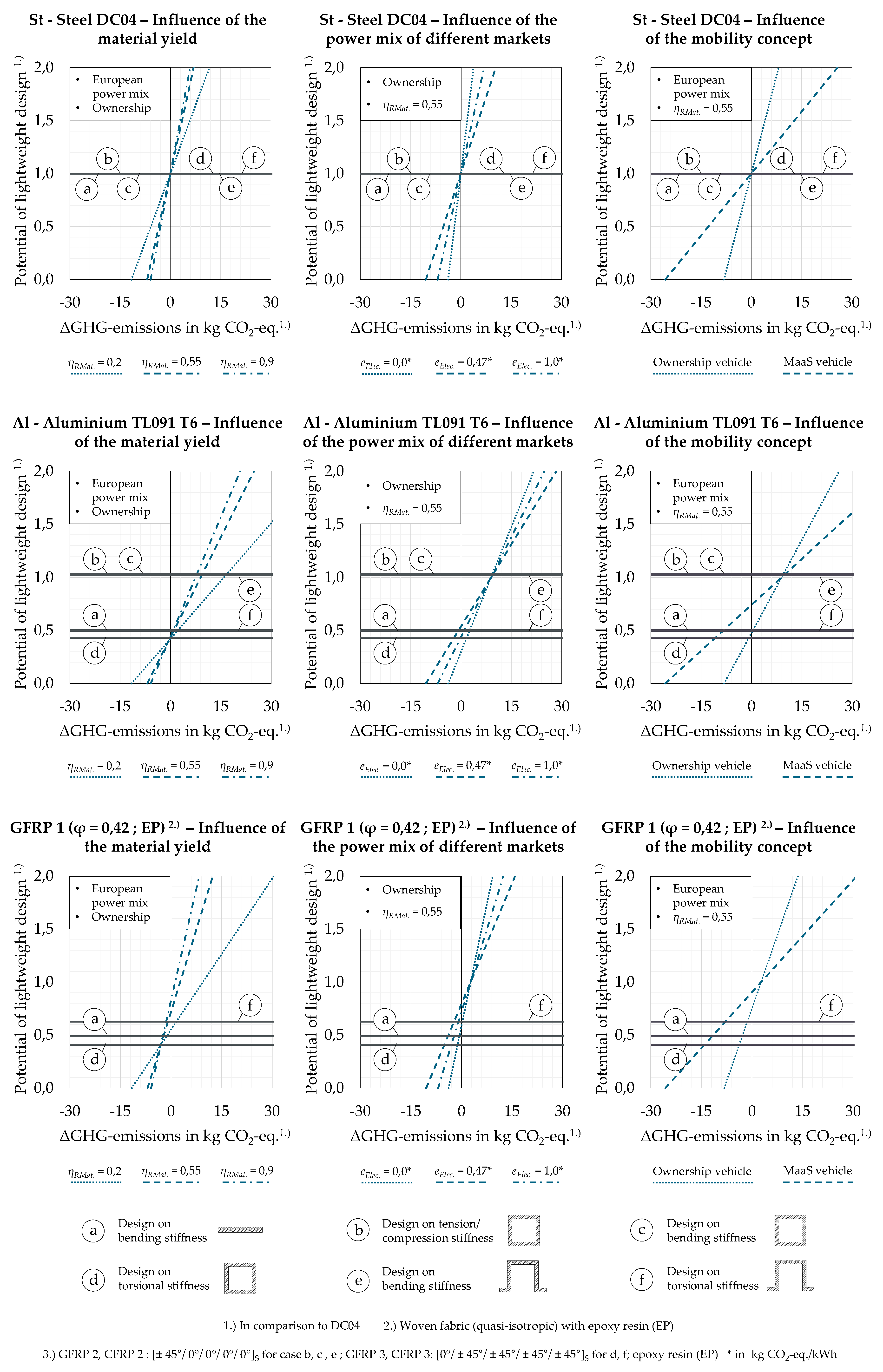
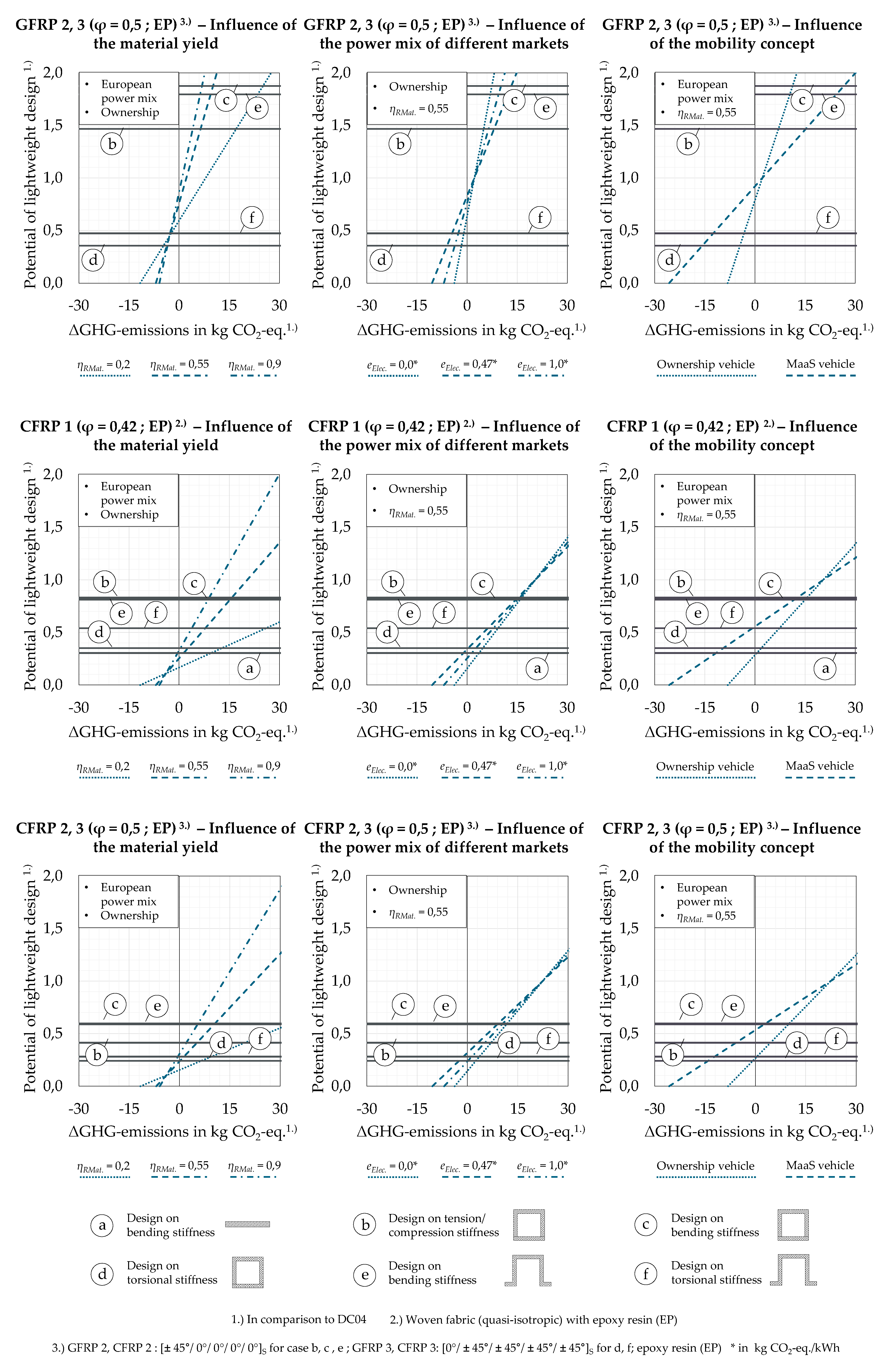
4.3. Part- and Vehicle-Specific Influencing Factors

The following section exemplarily highlights the influence of part- and vehicle-specific factors to life cycle GHG emissions. Table 3 shows different options for part-specific influence factors. In addition, Table 6 displays vehicle-specific influence factors considered within this study.
Figure 6 shows life cycle ΔGHG emissions of body parts by the examples of a thin-walled longitudinal member (Figure 6a) as well as an outer shell (Figure 6b) when replacing a reference steel design in steel DC04 with aluminum TL091 T6 and considering a design criterion bending stiffness and an ownership mobility concept with vehicle use in Europe as reference. The life cycle ΔGHG emissions of the investigated body parts are presented for different material yields. While the load cases like tension/compression, bending and torsion and manufacturing concepts are varied in Figure 6a, varying mobility concepts and vehicle sales markets are considered in Figure 6b.
Considering the same boundary conditions, e.g., adaption of sheet thickness and design on bending stiffness, the outer shell has a much higher lightweight potential through aluminum than the longitudinal member. Therefore, ΔGHG emissions over the entire life cycle are more likely to be negative for the case of shell designs in this substitution scenario, meaning that eco-efficiency could be increased. In addition, different lightweight potentials are reached through varying load cases, Figure 6a. Another major influence factor is the manufacturing concept of the body part. Higher material yields lead to lower GHG emissions, Figure 6a). Profile designs can reach higher manufacturing yields (80% to 95%) than shell designs (30% and 80% with an average of 60% [22]). However, the influence of manufacturing yields declines with a higher lightweight potential as well as higher scrap recirculation rates in manufacturing.
In addition, Figure 6b shows the influence of various markets (Europe, USA and China) and mobility concepts of the vehicle (Ownership and MaaS) on lifecycle ΔGHG emissions of a body part. Market differences result from different GHG emissions for electricity supply (China: currently highest impact per kWh; EU: currently lowest impact per kWh). Here, only current average values for the GHG emissions for electricity supply of five different markets are analyzed. A higher resolution considering more markets and future scenarios is possible and desirable for future work.
Vehicles in MaaS are assumed to undergo extended vehicle use periods (600,000 km vs. 200,000 km in ownership). At the same time, energy saving through weight reduction tends to be increased compared to ownership models due to their primary operation in urban areas compared to the average WLTC (Worldwide harmonized Light vehicles Test Cycle) driving cycle assumed for ownership vehicles.

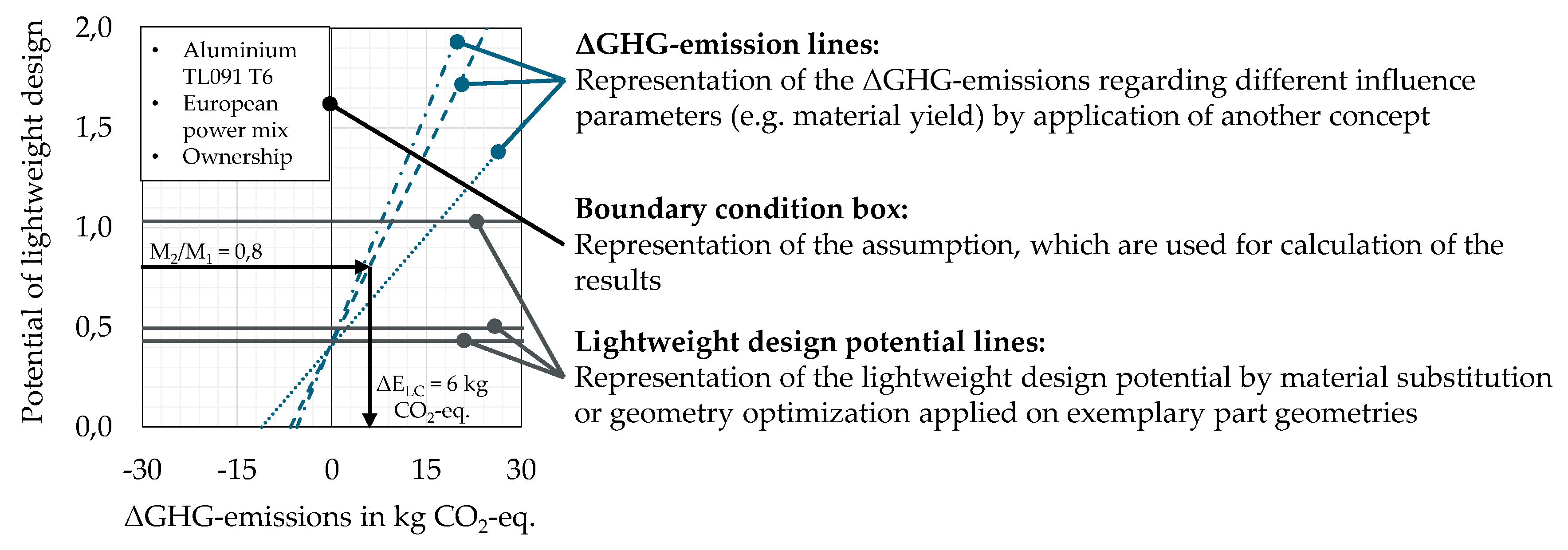
4.4. Interpretation and Visualization of Results

The previous section highlighted that part-specific (e.g., geometrical shape and loading) as well as vehicle-specific (e.g., market, mobility concept) properties have a major influence on lifecycle ΔGHG emissions when comparing a new conceptual design to a reference component. Therefore, a decision support is necessary that helps to handle variable environmental impacts during the conceptual design stage. Figure 7 shows the ΔGHG emissions of a new component concept compared to a reference body part. The x-axis represents the reduction (negative value) or increase (positive value) of the lifecycle ΔGHG-emissions which can be achieved through that concept. The y-axis shows the potential of lightweight design, which can be reached by the new concepts in comparison to the reference design. A value smaller than 1 describes a weight saving relating to the reference concept. Accordingly, a value larger than 1 describes an increase of the weight of the investigated body part. In the upper left area, a boundary condition box is represented. This box defines the vehicle-specific influencing factors for the environmental assessment, as described previously.
ΔGHG-emissions lines are plotted in the chart. Those describe influences of single parameters—e.g., degree of manufacturing yield—to lifecycle GHG emissions (see Section 4.2). The ΔGHG-emission lines are overlaid with lightweight design potential lines of specific part geometries (see Section 4.1). Looking at the intersection point, the assumed reduction or increase of GHG-emissions can be determined by consideration of a given potential of lightweight design and the choice of the relevant influence factors. The results are scaled to 1 kg of the reference concept.

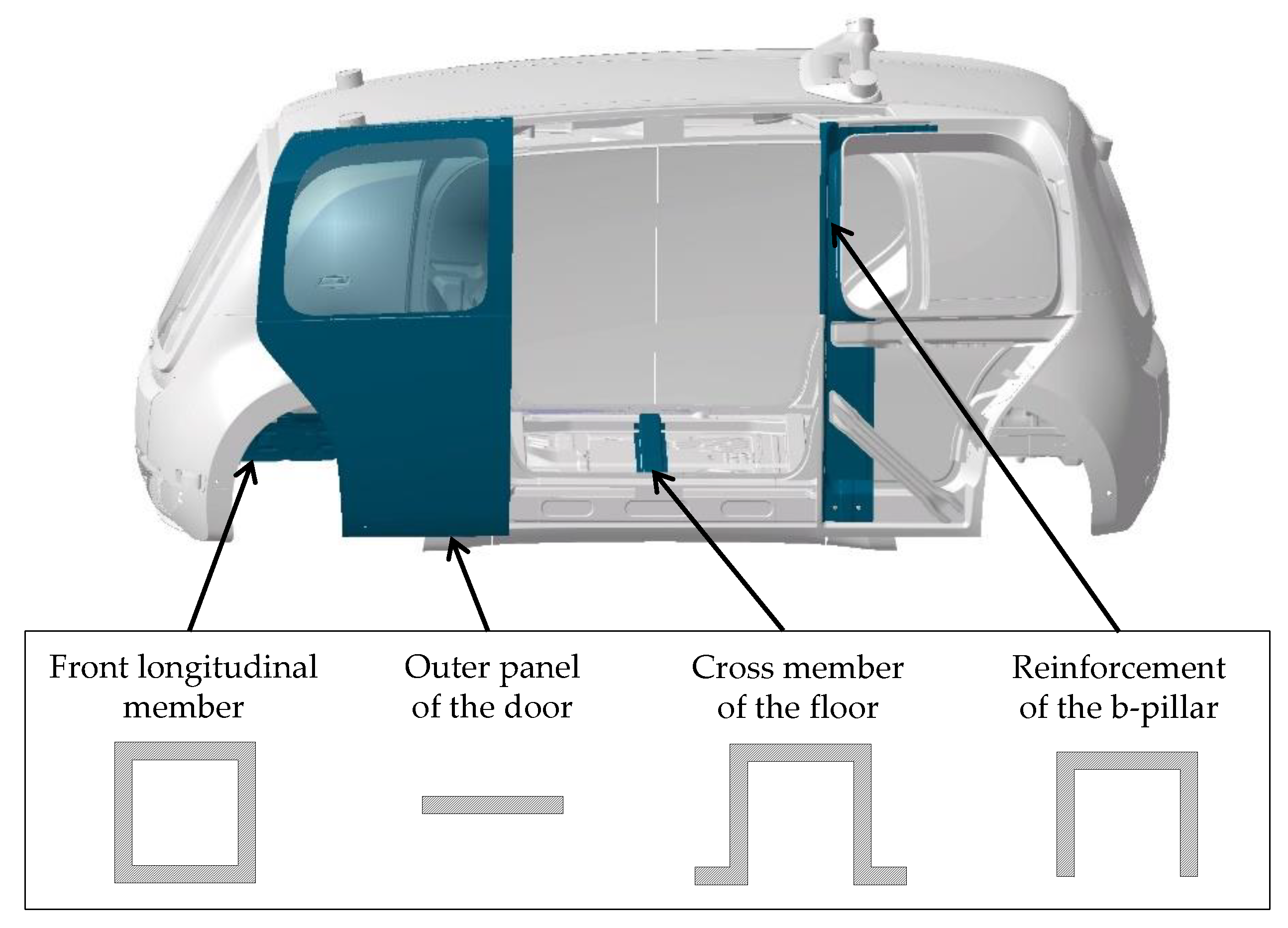
5. Verification of the Concept by Means of a Case Study

Figure 8 shows simplified abstractions of typical part geometries of body parts based on a future vehicle concept. Outer and inner panels and structural parts are distinguished [37]. While outer and inner panels usually are loaded on bending stiffness, structural parts have to fulfill different load cases and design criteria [37,38]. The case study is limited to stiffness-related combinations, such as the most prevalent load case in vehicle structures and respective body parts [39]. However, other load cases, e.g., the B-pillar reinforcement, as presented in Figure 7, would follow equivalent methodological steps.
According to the design method described in Section 4.1, the lightweight design potential by application of lightweight materials in different load cases can be determined (Table 7). It is assumed that profile geometries are thin-walled and sheet thickness around the profile middle is adapted for an equivalent mechanical design.
Besides conventional steel and aluminum concepts, quasi-isotropic FRP (GFRP1, CFRP1) as well as FRP designed in tension/compression and bending load cases (GFRP 2, CFRP 2) are analyzed. In addition, FRP designed on torsional load cases (GFRP 3, CFRP 3) are investigated. The mechanical and ecological properties of these materials are shown in Table A1.

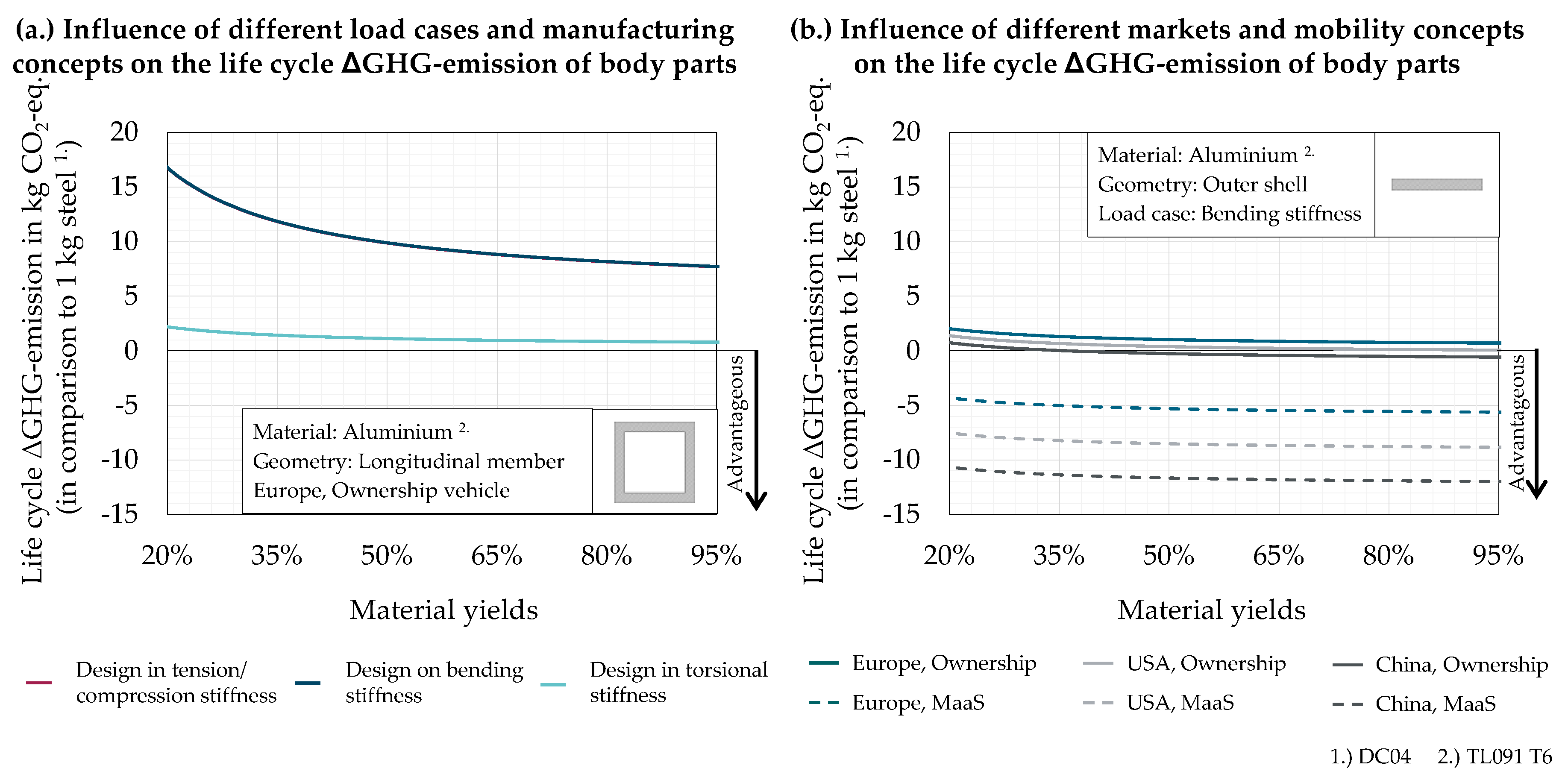
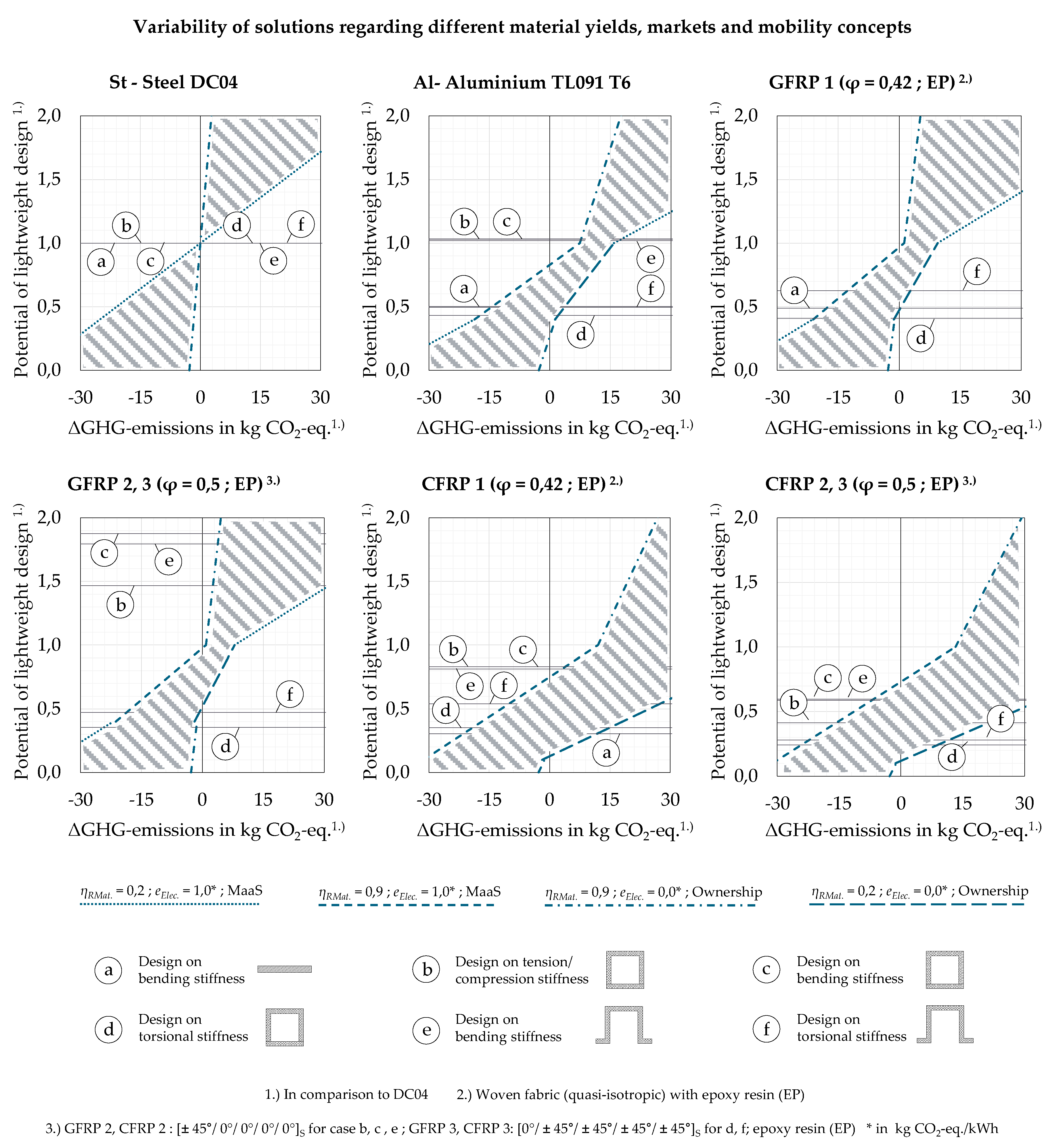
5.1. Joint Interpretation and Visualization of Part—And Vehicle-Specific Influence Fators

Figure 9 displays the ΔGHG-emissions of body part concepts with respect to variability within a potential vehicle life cycle. The shaded area defines the solution space regarding the vehicle-specific influence factors, which are described in Section 4.3. A factor-specific evaluation is provided within Figure A1 and Figure A2 of the Appendix A. The limits of the areas are defined by the relations described in Table 8. The best case is defined through a MaaS approach and an electricity mix with high GHG emissions per kWh, the worst case through an ownership vehicle approach and an electricity mix with low GHG emissions per kWh. The value of the lightweight design potential p depends on the GHG emissions in upstream chain of the different materials and manufacturing stage.
The following insights can be derived:
  • For outer and inner panels, Al1 and GFRP 1 concepts are in most cases advantageous compared to reference steel designs. Only vehicle part concepts that are operated in an ownership mobility concept, an electricity mix with low emissions and a low manufacturing yield are expected to lead to higher life cycle impacts than the reference. The GFRP 1 concept is slightly advantageous to the Al1 concept.
  • For structural parts, which are designed on tension/compression or bending stiffness, only CFRP 2 concepts are competitive against reference steel concepts. The higher the impacts of the electricity mix per kWh and the manufacturing yield and considering an MaaS operation, the more likely it is that the CFRP 2 concepts are advantageous. For bending load cases, this condition is more relevant than for tension/compression load cases.
  • For structural parts, which are designed on torsional stiffness, aluminum and GFRP concepts are in most cases advantageous compared to steel concepts, with GFRP 3 concepts being most advantageous. Only within an ownership mobility concept and a use stage, an electricity mix with low emissions, while simultaneously expecting a low degree of manufacturing yield, these concepts are not advantageous.
Detailed results are presented in Table 8.

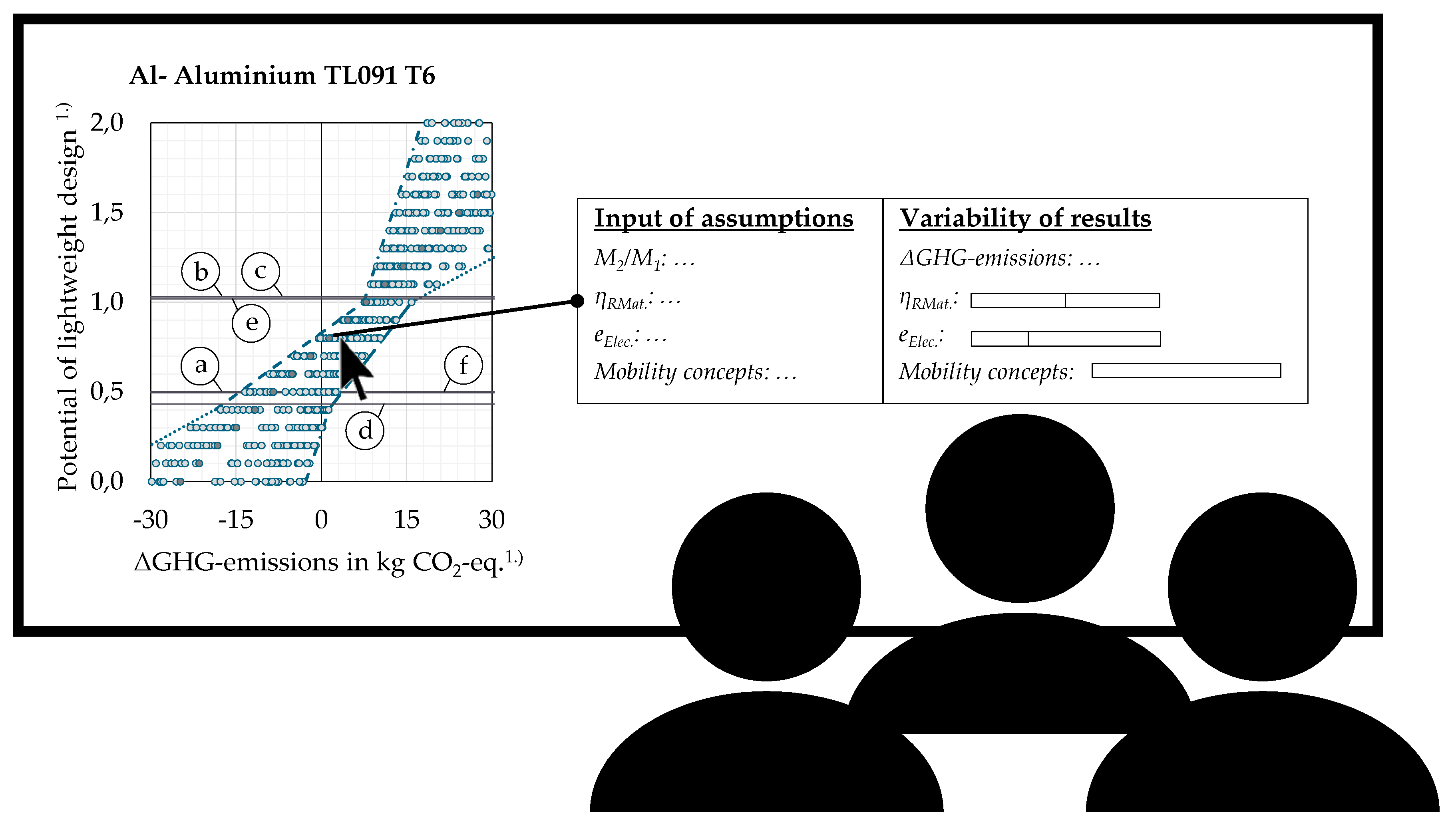
5.2. Interactive Visualization as Part of The Design Process

Figure 10 schematically illustrates how the integrated results visualization can be applied in engineering contexts. Through an interactive visualization of the possible results in the solution space, e.g., via scatterplots, the ΔGHG-emissions, e.g., for different material concepts, can be determined for a given lightweight design potential regarding different vehicle-specific influence factors. Engineers can set single life cycle parameters according to the context of component development, e.g., addressed markets or boundaries of the vehicle life cycle. Thus, the solution space can be narrowed down and insights about potential benefits or burdens over the life cycle of specific conceptual designs can be derived. The interactivity of the design tool enables engineers to analyze environmental impacts of varying body concepts hand in hand with the engineering of those parts. Due to this fact, the design process can be accelerated. Moreover, a digital tool is updateable and gives engineers the possibility of considering the dynamics of other influence factors like future scenarios or further driving cycles and mileages, etc.

6. Conclusions and Outlook

6.1. Conclusions

With the presented method, a workflow and implementation for the conceptual design of vehicle body parts with low environmental impacts is enabled. This comprises a design method, a linked assessment for life cycle environmental impacts as well as joint interpretations of both disciplines. The visualization of ΔGHG-emissions over the life cycle illustrates the relation between achievable weight reductions of conceptual design compared to a reference as well as the range of potential reductions or increases in life cycle environmental impacts for that comparison. Thus, based on a structured evaluation methodology, an accessible tool is provided to engineering designers.
Variability of life cycle impacts is displayed within those charts, as ΔGHG-emissions of electric vehicles depend on both part- and vehicle-specific influences that might not have been set at the early conceptual design phase. Thus, potential benefits of conceptual designs can be determined with respect to the associated boundary conditions. In addition, if e.g., vehicle specific influence factors have been defined, the range of estimated impacts can be narrowed down through interactive manipulation of the obtained charts. Due to the application of the tool in an early concept phase, the fulfillment of ecological requirements of the product can be guaranteed. So, change loops, which are currently needed for the improvement of ecological requirements of a vehicle can be reduced. Finally, this method contributes to decrease vehicle life cycle GHG-emissions.

6.2. Outlook

Whereas the present research shows a methodology that contributes to the field in line with the identified demands, several opportunities for further research and generalization occur. Opportunities for further research have been identified in the course its application at Open Hybrid LabFactory. The public-private partnership focuses on research on vehicle components. Hence, the authors could receive feedback from experts in automotive conceptual design.
  • The proposed design method targets single part replacements based on simplified geometries. While providing good insights for a range of applications in automotive industry, further refinement will be performed. This especially targets automated generations of conceptual designs of multiple parts at a time within a given installation space. While the proposed approach allows an extension towards addressing those issues, a major challenge lies in the design of algorithms to handle computational complexity.
  • The LCA-based evaluation methodology applies simplifications in relating product and process parameters with resulting environmental impacts. For example, future efficiency gains or market effects have not been considered and only average values for the GHG emissions of electricity supply are analyzed. A higher resolution of the markets is desirable. In addition, future GHG emissions for electricity supply decrease due to the application of renewable energy sources. Therefore, it is to be expected that the emission intensive production of e.g., FRP decrease. Omitting those effects limits the accuracy of the obtained results, especially in the case of materials with an emission intensive production. As well, the characterization of mobility concepts should be refined as assumed energy reduction values and lifetime mileages represent assumptions at the current stage. Furthermore, the sole evaluation of GHG emissions is not sufficient for complex technical systems. This also includes the introduction of constraints with relation to global sustainability goals.
  • The derived models and engineering charts can and will be applied to a number of further design processes within automotive manufacturing. More detailed feedback from engineering designers and project managers is expected to obtain further requirements on evaluation methods as well as the representation of results in engineering charts or tools. This could lead to the introduction of further design parameters or omission of others. As well, benefits and obstacles of static engineering charts to interactive representations will be elaborated for the specific case. While the first provides direct decision support based on a predefined scenario, interactive charts could lead users to form and test own hypotheses.
The combined design and assessment method proposed in this research can be generalized and transferred to other technical products. In principle, this is true for all applications that discuss material substitution scenarios of structural parts. Examples could be other vehicle types, e.g., motorcycles, commercial vehicles or interior parts of airplanes, for which only specific parameters would need to be adjusted. However, the current approach is limited in all cases that cannot allow material decisions to be influenced by other factors than mechanical performance, e.g., structural parts in aviation industry, and thus apply highly sophisticated computer-aided design methods already in the earliest concept phases.

Author Contributions

L.R. & A.K.: Conceptualization, methodology development & case study; writing of original draft and revisions; F.C.: Methodology development, review & editing; J.M., T.V. and C.H.: Supervision, review & editing. All authors have read and agreed to the published version of the manuscript.

Funding

This research received no external funding.

Conflicts of Interest

The authors declare no conflict of interest.

Appendix A

Table A1. Mechanical properties of different semi-finished products.
Semi-Finished ProductIndexMaterial Properties
Ex 1.)Ex 2.)Gρ
[N/mm2][N/mm2][N/mm2][kg/m3]
DC04St210,000210,00079,3007850
TL091 T6Al70,00070,00025,5002700
GFRP (φ = 0,42; EP; quasi-isotropic)GFRP 118,20018,20033001700
GFRP (φ = 0,5; EP;
[±45°/0°/0°/0°/0°]S)
GFRP 233,20025,80054001820
GFRP (φ = 0,5; EP;
[0°/±45°/±45°/±45°/±45°]S)
GFRP 317,70025,20094001820
CFRP (φ = 0,42; EP; quasi-isotropic)CFRP 146,60046,60032001450
CFRP (φ = 0,5; EP;
[±45°/0°/0°/0°/0°]S)
CFRP 297,00067,30091001500
CFRP (φ = 0,5; EP;
[0°/±45°/±45°/±45°/±45°]S)
CFRP 334,70064,80024,9001500
1.) Tension/compression; 2.) Bending.
Table A2. Inventory datasets applied to assess semi-finished products, adjusted for alloying elements and fiber-mass-ratios within calculation.
Semi-Finished ProductDescriptionRegionMaterial CompositionLife Cycle Inventory Dataset(s) Used as a BasisSource
DC04Steel sheetGermanyC 0,08%
P 0,030%
S 0,030%
Mn 0,4%
569eb248-58e3-4c3b-87dc-28370e15bd77http://www.gabi-software.com/support/gabi/gabi-database-2019-lci-documentation/
TL 091 T6Aluminum sheetGermanySi 0,40–0,80%
Fe 0,70%
Cu 0,15–0,40%
Mn 0,15%
Mg 0,80–1,2%
Cr 0,04–0,35%
Zn 0,25%
Ti 0,15%
dfd81ac6-600b-4867-b59a-c27aa33c5763
GFRPGlass FiberGermanyfiber-mass-ratios: 0,42 & 0,5ee377281-8d03-4dbe-90bf-fa51f61556a2
CFRPCarbon FiberGermanyd2e4cb14-c5fa-49a3-b6c2-840a2b860d63
GFRP, CFRPEpoxy resinGermany50125a08-978e-4156-bcc0-2d13ec3b49c7
GFRP: Glass Fiber Reinforced Plastics; CFRP: Carbon Fiber Reinforced Plastics.
Table A3. Inventory datasets applied to assess manufacturing processes for body part manufacturing.
Manufacturing ProcessApplied for Semi-Finished ProductsLife Cycle Inventory Dataset(s) Used as a BasisSource
Deep drawingDC041c32edbb-3602-4a7a-81cd-244f82ebb3b6http://www.gabi-software.com/support/gabi/gabi-database-2019-lci-documentation/
Deep drawingTL 091 T6ac011c4e-ef9a-49ee-9302-2f8e1ecf4c05.xml
Resin Transfer Molding (RTM)GFRP,
CFRP
12,8 MJ/kg[40]
PultrusionGFRP,
CFRP
3,1 MJ/kg[40]
Table A4. Assumptions to assess use stage energy demands.
Assumptions for the Assessment of the Use Stage
Nr.ParameterValueUnitSource
1Powertrain efficiencyηTrac.85,0% [27]
2Recuperation efficiencyηRegen.80,0% [21]
3Battery charge efficiencyηChar.90,0% [27]
4Rolling resistence coefficientcr0,7% [27]
5Energy reduction valueeERV3,0E-05kWh/km*kgOwn calculation
Table A5. Inventory datasets applied to assess efforts at vehicle end-of-life.
ProcessLife Cycle Inventory Dataset(s) Used as a BasisSource
Car shredder9913bb52-74bc-47ae-b794-d80ee214705chttp://www.gabi-software.com/support/gabi/gabi-database-2019-lci-documentation/professional-database-2019/
Figure A1. ΔGHG-emissions of different body part concepts regarding different influence factors (1).
Sustainability 12 05838 g0a1
Figure A2. ΔGHG-emissions of different body part concepts regarding different influence factors (2).
Sustainability 12 05838 g0a2

Symbols

Amm2Area of the cross section
a-Normalized area of the cross section
bmmBreadth
EMPaE-modulus
eDMat.kg CO2-eq./kgMat.Specific environmental credit related to material recovery
eElec.kg CO2-eq./kgMat.Specific environmental impact related to electricity production
eEMat.kg CO2-eq./kgMat.Specific environmental impact related to recycling
eEoLkg CO2-eq./kgMat.Specific environmental impact in End-of-Life
eERVkWh/100 km * 100 kgSpecific energy reduction value
eLCkg CO2-eq./kgMat.Specific environmental impact
eMat.kg CO2-eq./kgMat.Specific environmental impact in upstream chain
eProd.kg CO2-eq./kgMat.Specific environmental impact in manufacturing stage
ePres.kg CO2-eq./kgMat.Specific environmental impact related to production process
eRMat.kg CO2-eq./kgMat.Specific environmental impact related to material production
eSMat.kg CO2-eq./kgMat.Specific environmental credit related to material recovery
eUsekg CO2-eq./kgMat.Specific environmental impact in use stage
hmmHeight
Iymm4Moment of inertia
iy-Normalized moment of inertia
K(x)mm4Shape function of the bending line
lmmLength
Mkg/(mm2 * N)0,5Mass index
M2/M1-Potential of lightweight design
mkgMass
tmmThickness
q(x)N/mmShape function of the line load
qz(x)N/mmFunction of the line load
q0N/mmIncrease factor of the line load
sLCkmMileage
w(x)mmFunction of the bending line
xmmGeometry parameter
zmmDesign parameter
α-Relation parameter
ρkg/mm3Density
ηChar.-Efficiency for battery charging
ηDMat.-Material recovery rate in recycling process
ηEMat.-Share of originally used material, which is recycled
ηRMat.-Material efficiency in production process
ηSMat.-Material recovery rate in production process

References

  1. Gude, M.; Lieberwirth, H.; Meschut, G.; Tekkaya, A.E.; Zäh, M.F. FOREL Studie 2018. Available online: https://plattform-forel.de/studie/ (accessed on 30 May 2020).
  2. Volkswagen, A.G. Klimabilanz von E-Fahrzeugen & Life Cycle Engineering. 2019. Retrieved September 22, 2019. Available online: https://uploads.volkswagen-newsroom.com/system/production/uploaded_files/14448/file/da01b16ac9b580a3c8bc190ea2af27db4e0d4546/Klimabilanz_von_E-Fahrzeugen_Life_Cycle_Engineering.pdf (accessed on 25 May 2020).
  3. Hauschild, M.Z.; Herrmann, C.; Kara, S. An Integrated Framework for Life Cycle Engineering. Procedia CIRP 2017, 61, 2–9. [Google Scholar] [CrossRef] [Green Version]
  4. Kelly, J.C.; Sullivan, J.L.; Burnham, A.; Elgowainy, A. Impacts of Vehicle Weight Reduction via Material Substitution on Life-Cycle Greenhouse Gas Emissions. Environ. Sci. Technol. 2015, 49, 12535–12542. [Google Scholar] [CrossRef] [PubMed]
  5. Herrmann, C.; Dewulf, W.; Hauschild, M.; Kaluza, A.; Kara, S.; Skerlos, S.; Engineering, L.C. Life cycle engineering of lightweight structures. CIRP Ann. 2018, 67, 651–672. [Google Scholar] [CrossRef]
  6. Egede, P. Environmental Assessment of Lightweight Electric Vehicles. In Environmental Assessment of Lightweight Electric Vehicles; Springer International Publishing: Cham, Switzerland, 2017. [Google Scholar] [CrossRef]
  7. Goede, M.; Stehlin, M.; Rafflenbeul, L.; Kopp, G.; Beeh, E. Super Light Car- Lightweight Construction Thanks to a Multi-Material Design and Function Integration. Eur. Transp. Res. Rev. 2009, 1, 5–10. [Google Scholar] [CrossRef] [Green Version]
  8. Nehuis, F.; Kleemann, S.; Egede, P.; Vietor, T.; Herrmann, C. Future Trends in the Development of Vehicle Bodies Regarding Lightweight and Cost. In Innovative Design, Analysis and Development Practices in Aerospace and Automotive Engineering; Springer: New Delhi, India, 2014; pp. 13–21. [Google Scholar] [CrossRef]
  9. Kaluza, A.; Kleemann, S.; Fröhlich, T.; Herrmann, C.; Vietor, T. Concurrent Design & Life Cycle Engineering in Automotive Lightweight Component Development. Procedia CIRP 2017, 66, 16–21. [Google Scholar] [CrossRef]
  10. Cox, B.; Mutel, C.L.; Bauer, C.; Mendoza Beltran, A.; van Vuuren, D.P. Uncertain Environmental Footprint of Current and Future Battery Electric Vehicles. Environ. Sci. Technol. 2018, 52, 4989–4995. [Google Scholar] [CrossRef]
  11. Cerdas, F.; Thiede, S.; Herrmann, C. Integrated Computational Life Cycle Engineering—Application to the case of electric vehicles. CIRP Ann. Manuf. Technol. 2018, 67, 25–28. [Google Scholar] [CrossRef]
  12. Kaluza, A.; Gellrich, S.; Cerdas, F.; Thiede, S.; Herrmann, C. Life Cycle Engineering Based on Visual Analytics. Procedia CIRP 2018, 69, 37–42. [Google Scholar] [CrossRef]
  13. Göpfert, I.; Braun, D.; Schulz, M. (Eds.) Automobillogistik—Stand und Zukunftstrends; Springer Gabler: Wiesbaden, Germany, 2017. [Google Scholar] [CrossRef]
  14. Feldhusen, J.; Grote, K.-H. (Eds.) Pahl/Beitz Konstruktionslehre; Springer Vieweg: Berlin/Heidelberg, Germany, 2007. [Google Scholar] [CrossRef]
  15. Duce, A.D.; Egede, P.; Öhlschläger, G.; Dettmer, T.; Althaus, H.-J.; Bütler, T.; Szczechowicz, E. eLCAr—Guidelines for the LCA of Electric Vehicles. Proj.no. 285571. (Report from Project “E-Mobility Life Cycle Assessment Recommendations”. EU Seventh Framework Programme—FP7/2007–2013. Available online: http://www.elcar-project.eu/downloads/guidelines/ (accessed on 22 June 2020).
  16. Krinke, S. Implementing Life Cycle Engineering efficiently into Automotive Industry Processes. In Glocalized Solutions for Sustainability in Manufacturing; Springer: Berlin/Heidelberg, Germany, 2011; pp. 11–16. [Google Scholar] [CrossRef]
  17. Cerdas, F.; Egede, P.; Herrmann, C. LCA of Electromobility. In Life Cycle Assessment; Hauschild, M., Rosenbaum, R., Olsen, S., Eds.; Springer: Cham, Switzerland, 2018. [Google Scholar] [CrossRef]
  18. Schönemann, M.; Schmidt, C.; Herrmann, C.; Thiede, S. Multi-level Modeling and Simulation of Manufacturing Systems for Lightweight Automotive Components. Procedia CIRP 2016, 41, 1049–1054. [Google Scholar] [CrossRef] [Green Version]
  19. Broch, F. Integration von Ökologischen Lebenswegbewertungen in Fahrzeugentwicklungsprozesse; Springer Fachmedien: Wiesbaden, Germany, 2017. [Google Scholar] [CrossRef]
  20. Delogu, M.; Zanchi, L.; Dattilo, C.A.; Pierini, M. Innovative composites and hybrid materials for electric vehicles lightweight design in a sustainability perspective. Mater. Today Commun. 2017, 13, 192–209. [Google Scholar] [CrossRef]
  21. Ermolaeva, N.S.; Castro, M.B.G.; Kandachar, P.V. Materials selection for an automotive structure by integrating structural optimization with environmental impact assessment. Mater. Des. 2004, 25, 689–698. [Google Scholar] [CrossRef]
  22. Grujicic, M.; Sellappan, V.; He, T.; Seyr, N.; Obieglo, A.; Erdmann, M.; Holzleitner, J. Total life cycle-based materials selection for polymer metal hybrid body-in-white automotive components. J. Mater. Eng. Perform. 2009, 18, 111–128. [Google Scholar] [CrossRef]
  23. Poulikidou, S.; Schneider, C.; Björklund, A.; Kazemahvazi, S.; Wennhage, P.; Zenkert, D. A material selection approach to evaluate material substitution for minimizing the life cycle environmental impact of vehicles. Mater. Des. 2015, 83, 704–712. [Google Scholar] [CrossRef] [Green Version]
  24. Mayyas, A.T.; Qattawi, A.; Mayyas, A.R.; Omar, M.A. Life cycle assessment-based selection for a sustainable lightweight body-in-white design. Energy 2012, 39, 412–425. [Google Scholar] [CrossRef]
  25. Mayyas, A.R.T.; Mayyas, A.R.T.; Omar, M. Sustainable Lightweight Vehicle Design: A Case Study in Eco-Material Selection for Body-In-White. In Lightweight Composite Structures Transport Design Manufacturing Analusis Performance; Elsevier Ltd.: Amsterdam, The Netherlands, 2016; pp. 267–302. [Google Scholar] [CrossRef]
  26. Kaspar, J.; Vielhaber, M. Sustainable Lightweight Design—Relevance and Impact on the Product Development & Lifecycle Process. Procedia Manuf. 2017, 8, 409–416. [Google Scholar] [CrossRef]
  27. Kaspar, J.; Vielhaber, M. Integrated Cross-Component Lightweight and Material-Oriented Development Methodology—The Embodiment Design Cycle. Procedia CIRP 2018, 70, 481–486. [Google Scholar] [CrossRef]
  28. Stoffels, P.; Kaspar, J.; Baehre, D.; Vielhaber, M. Holistic Material Selection Approach for More Sustainable Products. Procedia Manuf. 2017, 8, 401–408. [Google Scholar] [CrossRef]
  29. Delogu, M.; Del Pero, F.; Zanchi, L.; Pierini, M.; Maltese, S.; Bonoli, A.; Bonoli, A. Challenges for modelling and integrating environmental performances in concept design: The case of an automotive component lightweighting. Int. J. Sustain. Eng. 2018, 11, 135–148. [Google Scholar] [CrossRef]
  30. Take-Home Messages from the Applications of Life Cycle Assessment on Lightweight Automotive Components. Available online: https://www.sae.org/publications/technical-papers/content/2018-37-0029/ (accessed on 5 April 2020).
  31. Dattilo, C.A.; Zanchi, L.; Del Pero, F.; Delogu, M. Sustainable design: An integrated approach for lightweighting components in the automotive sector. In Smart Innovation, Systems and Technologies; Springer: Berlin, Germany, 2017. [Google Scholar] [CrossRef]
  32. Luk, J.; Kim, H.; De Kleine, R.; Wallington, T.; MacLean, H. Review of the Fuel Saving, Life Cycle GHG Emission, and Ownership Cost Impacts of Lightweighting Vehicles with Different Powertrains. Environ. Sci. Technol. 2017, 51, 8215–8228. [Google Scholar] [CrossRef]
  33. Luk, J.; Kim, H.; De Kleine, R.; Wallington, T.; MacLean, H. Greenhouse gas emission benefits of vehicle lightweighting: Monte Carlo probabalistic analysis of the multi material lightweight vehicle glider. Transp. Res. Part D Transp. Environ. 2018, 62, 1–10. [Google Scholar] [CrossRef]
  34. Kim, H.; Wallington, T. Life Cycle Assessment of Vehicle Lightweighting: A Physics-Based Model to Estimate Use-Phase Fuel Consumption of Electrified Vehicles. Environ. Sci. Technol. 2016, 50, 11226–11233. [Google Scholar] [CrossRef] [PubMed]
  35. Weißbach, W.; Dahms, M.; Jaroschek, C. Werkstoffe und Ihre Anwendungen; Springer Vieweg: Berlin, Germany, 2018. [Google Scholar] [CrossRef]
  36. Hofer, J. Sustainability Assessment of Passenger Vehicles: Analysis of Past Trends and Future Impacts of Electric Powertrains. ETH Zurich 2014, 22027. [Google Scholar] [CrossRef]
  37. Birkert, A.; Haage, S.; Straub, M. Umformtechnische Herstellung Komplexer Karosserieteile; Springer: Berlin/Heidelberg, Germany, 2013. [Google Scholar] [CrossRef]
  38. Braess, H.-H.; Seiffert, U. (Eds.) Vieweg Handbuch Kraftfahrzeugtechnik; ATZ/MTZ-Fachbuch; Springer Vieweg: Wiesbaden, Germany, 2016. [Google Scholar] [CrossRef]
  39. Friedrich, H.E. (Ed.) Leichtbau in der Fahrzeugtechnik; Springer Vieweg: Wiesbaden, Germany, 2013. [Google Scholar] [CrossRef]
  40. Suzuki, T.; Takahashi, J. Prediction of energy intensity of carbon fiber reinforced plastics for mass-produced passenger cars. Ninth Japan Int. SAMPE Symp. JISSE-9. 2005, pp. 14–19. Available online: http://j-t.o.oo7.jp/publications/051129/S1-02.pdf (accessed on 5 April 2020).
Figure 1. Body part development as part of foreground and background system development, prepared on the basis of Herrmann et al. and Kaluza et al. [5,9].
Sustainability 12 05838 g001
Figure 2. Overall methodology, organized in two pillars (A,B) and four levels (iiv).
Sustainability 12 05838 g002
Figure 3. Simplified loading and idealized cross section.
Sustainability 12 05838 g003
Figure 4. Life cycle inventory (LCI) model of body parts.
Sustainability 12 05838 g004
Figure 5. Interplay between parameters in conceptual design of body parts and environmental impact of conceptual designs.
Sustainability 12 05838 g005
Figure 6. Vehicle-specific influence factors on the lifecycle GHG emissions of body parts.
Sustainability 12 05838 g006
Figure 7. Decision support chart for environmentally compatible design of body parts.
Sustainability 12 05838 g007
Figure 8. Simplified abstractions of typical part geometries of body parts.
Sustainability 12 05838 g008
Figure 9. Variability of ΔGHG-emissions of body part concepts regarding different influence factors.
Sustainability 12 05838 g009
Figure 10. Application of the result presentation.
Sustainability 12 05838 g010
Table 1. State of research regarding the design of eco-efficient automotive body parts.
Ermolaeva et al. 2004 [21]Grujicic et al. 2009 [22]Poulikidou et al. 2015 [23]Mayyas et al. 2012, 2016 [24,25]Kaspar et al. 2017, Kaspar et al. 2018, Stoffels et al. 2017 [26,27,28]Egede 2017 [6]Delogu 2018 [29,30]
Dattilo 2017 [31]
Luk et al. 2017, Luk et al. 2018 [32,33]
Task 1: Conceptual Design
4 Issues addressed; 0 Issue not in focus of approach/unclear
Consideration of different materials44444404
Based on simplified product models00444000
Consideration of installation space00004000
Task 2: Life Cycle Assessment Taking into Account Variability
4 Issues addressed; 2 Issues partly discussed, e.g., sensitivity; 0 Issue not in focus of approach/unclear
Considered Life Cycle Stages
 Upstream Processes40444444
 Manufacturing (Gate-to-Gate)44444044
 Use Stage (Combustion/Electric)4/004/04/04/04/44/04/4
 End-of-Life44444044
Consideration of technological variability 20420020
Consideration of spatial variability00200400
Task 3: Interpretation and Prioritization of Concept Alternatives
4 Issues addressed; 0 Issue not in focus of approach/unclear
Quantitative Interpretation of Results44444444
Decision-support for Conceptual Design00004000
Table 2. Findings from analysis of the state of research.
TaskFindings
Task 1: Conceptual Design
  • All methods assist in introducing new materials into body parts.
  • Conceptual designs are based on simplified product models.
  • Boundary conditions on installation space as well as design freedom regarding part integration or separation are only regarded by few approaches.
Task 2: Life Cycle Assessment Taking into Account Variability
  • Almost all approaches take a full life cycle perspective when evaluating environmental impacts.
  • However, simplified approaches rely on static impact factors rather than sophisticated inventory models.
  • For the studies at the selected interface between component design and LCE (Life Cycle Engineering), the use stage is mostly analyzed for combustion engine vehicles; only one study focuses on electric vehicles.
  • However, there is a larger number of approaches within the state of research that quantify use stage effects of lightweighting for electrified vehicles. One example is presented by Kim & Wallington [34]. Their findings could easily be combined with the presented approaches in Table 1. Technological variability is considered by some approaches. However, temporal or spatial effects are neglected.
Task 3: Concurrent Interpretation and Prioritization of Concept Alternatives
  • Grujicic et al. provide a semi-quantitative interpretation, all other approaches rely on quantitative results.
  • Technological variabilities are evaluated by some approaches, e.g., through sensitivity plots.
  • Only the approaches by Kaspar et al. and Stoffels et al. directly address component design for obtained results.
Table 3. Part-specific influence factors on the lifecycle GHG (Greenhouse Gas) emissions of body parts.
Part-Specific Influence Factors on the Life Cycle ΔGHG-Emissions of Body Parts
Design ParameterOptions
Body part geometry Sustainability 12 05838 i001 Sustainability 12 05838 i002 Sustainability 12 05838 i003 Sustainability 12 05838 i004
Load caseTension/CompressionBendingTorsionBuckling
Design criterionStiffnessStrength
Table 4. Scope of Life Cycle Assessment model.
Life Cycle StageSystem Description
Upstream Processes
  • Provision of raw materials and semi-finished products based on state-of-the art processes.
  • Neglection of market availabilities, efficiency gains and regional influences on material production (further research required).
Manufacturing
  • Process energy and material demands for different manufacturing routes based on state-of-the-art processes.
  • Modelling of manufacturing yields and reintroduction of production scraps in component manufacturing and exploited production scraps.
  • Manufacturing in Germany.
Use
  • Component-based energy demand of electric vehicles.
  • Two mobility concepts: ownership vs. MaaS.
  • Influence of renewables in electricity provision for vehicle charging.
  • Neglection of service and repair scenarios (further research required).
End-of-Life
  • Modelling of efforts (process energy and materials) for end-of-life treatment and exploited waste.
  • No credits for secondary materials.
Table 5. Definition of the impact factors in the life cycle of a body part.
No.Life Cycle StageEquation
1Upstream processes Δ e M a t . = M 2 M 1 × ( e R M a t . 2 ( 1 η R M a t . 2 ) × η S M a t . 2 × e S M a t . 2 ) × 1 η R M a t . 2
        ( e R M a t . 1 ( 1 η R M a t . 1 ) × η S M a t . 1 × e S M a t . 1 ) × 1 η R M a t . 1
(15)
2Manufacturing Δ e P r o d . = M 2 M 1 × e P r e s . 2 η R M a t . 2 e P r e s . 1 η R M a t . 1 (16)
3Use Δ e U s e = s L C × e E R V × e E l e c . η C h a r . × ( M 2 M 1 1 ) (17)
4End-of-Life Δ e E o l . = M 2 M 1 × η E M a t . 2 × ( e R e c y , 2 η D M a t . 2 × e D M a t . , 2 )
                 η E M a t . 1 × ( e R e c y , 1 η D M a t . 1 × e D M a t , 1 )
(18)
Table 6. Vehicle-specific influence factors on the lifecycle GHG emissions of body parts.
Vehicle-Specific Influence Factors on the Life Cycle ΔGHG-Emissions of Body Parts
Design ParameterOptions
Manufacturing conceptShell constructionProfile construction
Mobility conceptOwnershipMobility-as-a-Service
Use stage electricity mix of different markets * [kg CO2-eq./kWh] Sustainability 12 05838 i005
* Average of the entire country.
Table 7. Potential of lightweight design for different part geometries in different load cases.
MaterialPotential of Lightweight Design
a.b.c.d.e.f.
Sustainability 12 05838 i006Bending Stiffness Sustainability 12 05838 i007Tension/Com-Pression Stiffness Sustainability 12 05838 i008Bending Stiffness Sustainability 12 05838 i009Torsional Stiffness Sustainability 12 05838 i010Bending Stiffness Sustainability 12 05838 i011Torsional Stiffness
St1,0001,0001,0001,0001,0001,000
Al0,4961,0321,0310,4321,0190,503
GFRP 10,4892,4992,4670,4092,3010,627
GFRP 2-1,4671,875-1,795-
GFRP 3---0,355-0,473
CFRP 10,3050,8320,8310,3510,8120,541
CFRP 2-0,4140,596-0,588-
CFRP 3---0,241-0,281
Adaption of the sheet thickness around the profile middle line; thin-walled profile geometries.
Table 8. Definition of the limits of the solution space.
Limit0 < M2/M1 ≤ pp < M2/M1 ≤ 11 < M2/M1 ≤ 2
Best case (left limit)ηRMat. ↓; eElec. ↑;
MaaS (eERV ↑; sLC ↑)
ηRMat. ↑; eElec. ↑;
MaaS (eERV ↑; sLC↑)
ηRMat. ↑; eElec. ↓;
Ownership (eERV ↓; sLC ↓)
Worst case (right limit)ηRMat. ↑; eElec. ↓;
Ownership (eERV ↓; sLC ↓)
ηRMat.↓; eElec. ↓;
Ownership (eERV ↓; sLC↓)
ηRMat. ↓; eElec. ↑;
MaaS (eERV ↑; sLC ↑)
↑: Highest possible value; ↓: Lowest possible value.

