1. Introduction
Electric vehicles (EVs) are increasingly popular, and as their technology continuously advances, they are becoming an essential part of transportation networks. Because EVs only use electrical energy, and not fuel, to operate, the adoption of EVs has significantly contributed to reducing greenhouse gases. EVs are powered by battery packs which are embedded on the EV chassis. The driving range of EVs strongly depends on the capacity of the battery, and battery research is also significantly increasing [
1,
2,
3,
4,
5,
6].
The limitations of present EV technology are the high cost of the battery, and their relatively limited driving range. To overcome these issues, hybrid electric vehicles (HEVs) and plug-in hybrid electric vehicles (PHEVs) have been introduced [
1,
2]. PHEVs can be recharged using an external power source like an EV. However, PHEVs are quite heavy because they have two operating systems: electric motor and internal combustion engine [
3].
A number of new technologies are being introduced to address the mentioned shortcomings of EV and PHEV, and to minimize dependency on battery systems. One promising technique, the wireless power transfer (WPT) system, transfers electrical energy wirelessly for EV charging [
4,
5,
6,
7,
8,
9]. The WPT system is convenient, and because electric charge is transferred wirelessly, it is safer, with less risk of electric shock or electrostatic discharge problem. In addition, the WPT is an essential technology for fully autonomous EVs. For these reasons, WPT-based EV charging has been actively studied by many research groups of various industries [
7,
8,
9]. The Society of Automotive Engineers (SAE) is a U.S.-based professional association and standards development organization for engineering professionals in various industries. Members include BMW, Daimler, Toyota, Nissan, Ford, Delphi, Jaguar, WiTricity, and the University of Auckland. The SAE J2954 recommended practice (RP), standardized after 2018, establishes a methodology for designing and testing WPT systems for EVs up to 11 kW power levels [
10]. SAE J2954 RP includes powering frequency, electrical parameters, specifications, procedures, and other factors to be evaluated. It describes the specific dimensions for ground assembly (GA) and vehicle assembly (VA) components, including the power transmitting coil (GA Coil) and receiving coil (VA Coil), respectively. It also includes the ranges of inductances of the GA Coil (L
GA), and VA Coil (L
VA), and coupling coefficient (
k), as well as the impedance matching values of the WPT system.
Evaluating the LGA and LVA values at the given range listed in SAE J2954 is important to ensure the interoperability of EV charging systems, which is essential for EV wireless charging. In addition, out-ranged inductance values are also introduced, as well as the out-ranged XGA and XVA values, which act as a filter on the charging circuit.
Although the standard provides the dimensions of the GA coil and VA coil, the inductance values of fabricated coils according to the specification are not always guaranteed to be within the range specified in the standard since there can be tolerance issue and unknown parameters which can affect the L
GA and L
VA values. Moreover, once the GA and VA coils are fabricated, the L
GA and L
VA values cannot be changed easily [
11,
12].
In this paper, we introduce an air-gap adjusting method to control the effective permeability of ferrite tiles so that the LGA and LVA values can be effectively fine-tuned. To set the LGA and LVA values within intended ranges, we slightly adjust the air-gap lengths between the ferrite tiles in a specific region. Since these air-gap lengths are not specifically described in the standard, it is reasonable to tune these values to control the inductances of the GA and VA coils. In the standard, there are four- power classification for the vehicles. According to the power transferring capacity and ground clearance range, the power class can be differed. In this paper, we consider the WPT2/Z2 class which have 7.7 kW in input power, with 140 mm to 210 mm ground clearance. The proposed method was applied to a set of GA and VA coils for WPT2/Z2 given in SAE J2954 RP to verify its feasibility. By adjusting the air-gap lengths between ferrite blocks, the LGA and LVA values were set close to the given ranges in the standard. The proposed concept was verified with simulations and experimental measurements based on an SAE J2954 RP test bench.
2. Dimensions of GA Coil and VA Coil on SAE J2954 RP
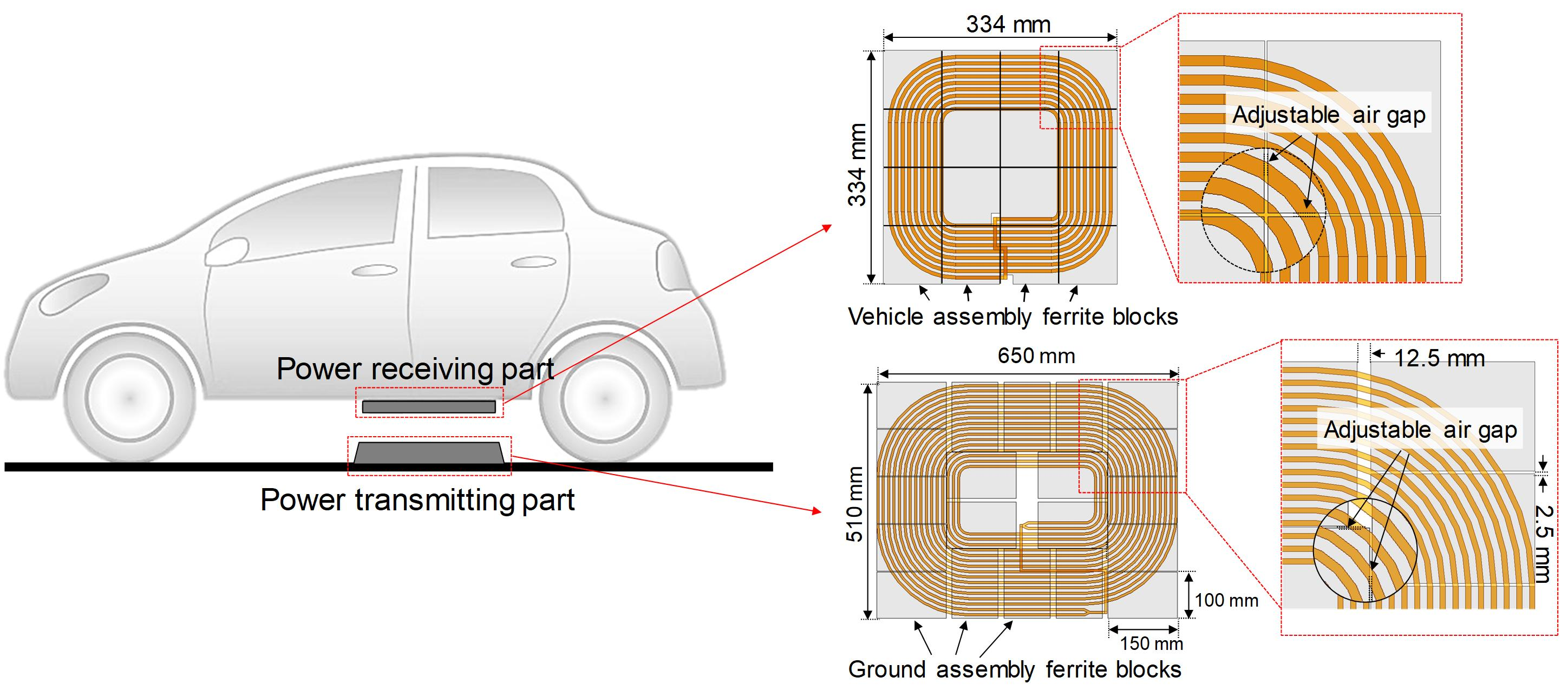
Referring to SAE J2954, the WPT for an EV is composed of a GA part and a VA part, as shown in
Figure 1a. The GA part includes an AC/DC converter, a DC/AC converter, a filter for impedance compensation, and a GA coil. The VA part includes the battery, rectifier, another filter for impedance compensation in the VA part, and the VA coil. As shown in
Figure 1a, both the GA and VA coils are connected to the impedance compensation parts, the filters.
This system can be represented as the equivalent circuit in
Figure 1b. The L
GA and L
VA values can be used to derive the range of the X
GA and X
VA, which are also restricted by the standard [
12]. The standard also provides the reference self-inductance range of the GA coil and VA coil, as well as a coupling coefficient, as listed in
Table 1.
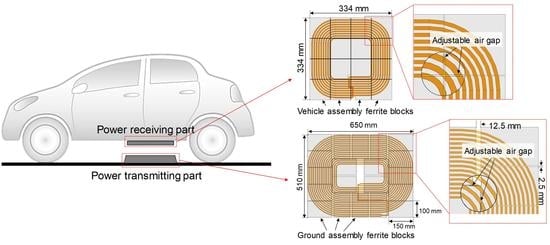
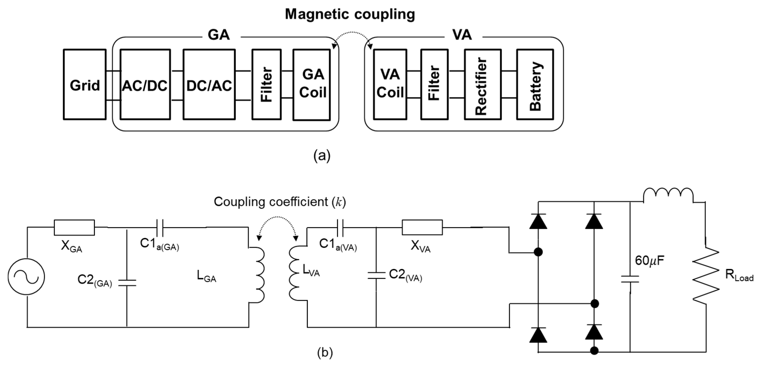
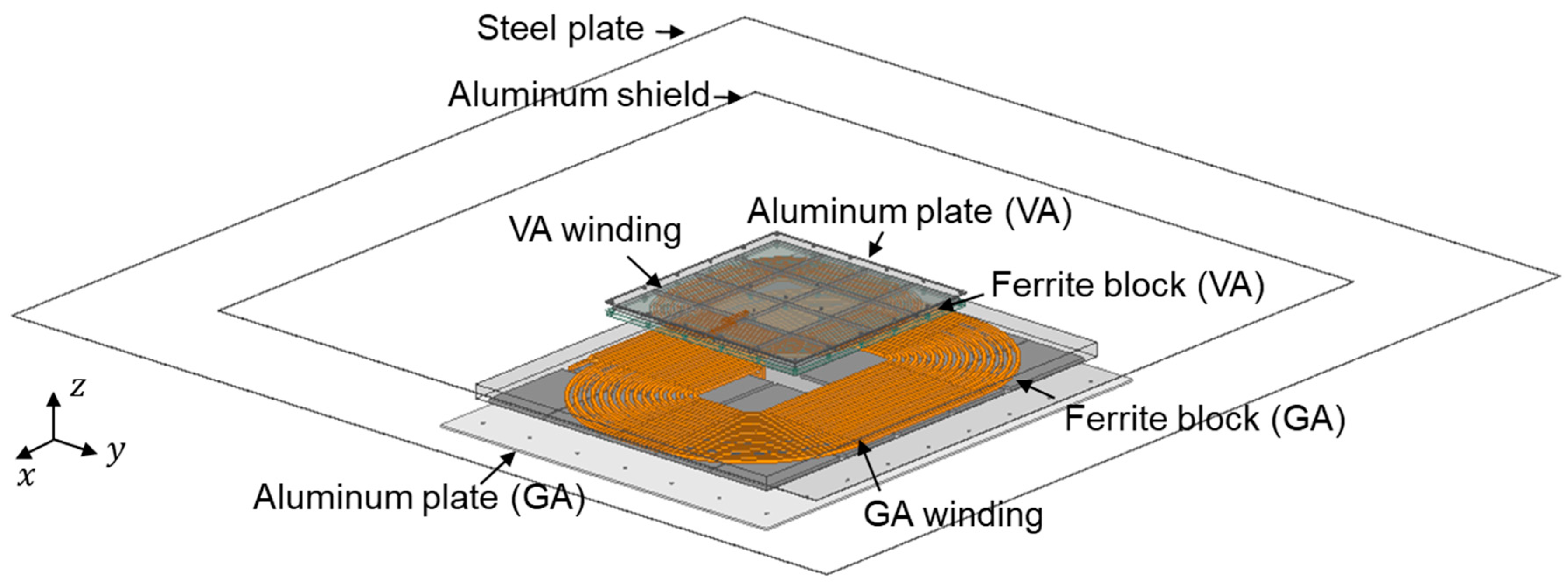
Figure 2 illustrates the assembly of the GA coil and VA coil in the WPT2/Z2 class. In
Figure 2a, the GA aluminum plate prevents electromagnetic field (EMF) interference, affected by the ground. The GA coil is wound with two parallel 5 mm diameter Litz wire with 9 turns each. A GA Litz tray is used to mount the GA winding and hold the GA ferrite tiles. 20 ferrite plates, each 5 mm thick, are located under the GA coil to introduce a higher coupling coefficient between the GA coil and VA coil.
The VA part, which receives a time-varying magnetic field, is composed of five components: a VA aluminum plate, VA ferrite tiles, VA winding, a VA Litz tray, an aluminum shield, and steel plate.
Figure 2b shows the dimensions of a VA coil in the WPT2/Z2 class. Like the GA coil configuration, The VA Litz tray is used to mount the VA winding, VA ferrite tiles, and VA aluminum plate. To shield the vehicle from magnetic field leakage, an aluminum shield is also applied. In this study, to represent the vehicle body, a 1.3 m × 1.3 m size steel plate was applied. The VA winding was wound with 5 mm diameter Litz wires with 9 turns, and 16 ferrite tiles, whose thickness was 5 mm, were located on top of the VA winding. These dimensions of the GA coil and VA coil are predefined in the SAE J2954 standard. However, although these dimensions are given, some discrepancies in the electric parameters can occur, including the resolution of the coil dimensions, ferrite blocks arrangement, joining screws, and the holes in the ferrite blocks and aluminum/steel plates. Considering the manufacturing tolerance of the given design, the fabricated GA and VA coil may have an out of range electrical parameter that is given in the standard, especially in terms of inductances and coupling coefficient. The self-inductance and mutual inductance between the two coils are dimensionally defined, including by the number of turns, the outer/inner radius of a coil, the thickness of the coil, and coil to coil distances, it is not easy to control self-inductance once they are fabricated [
11,
12].
3. Proposed Method to Tune the Self-Inductance and Coupling Coefficient by Modifying the Effective Permeability
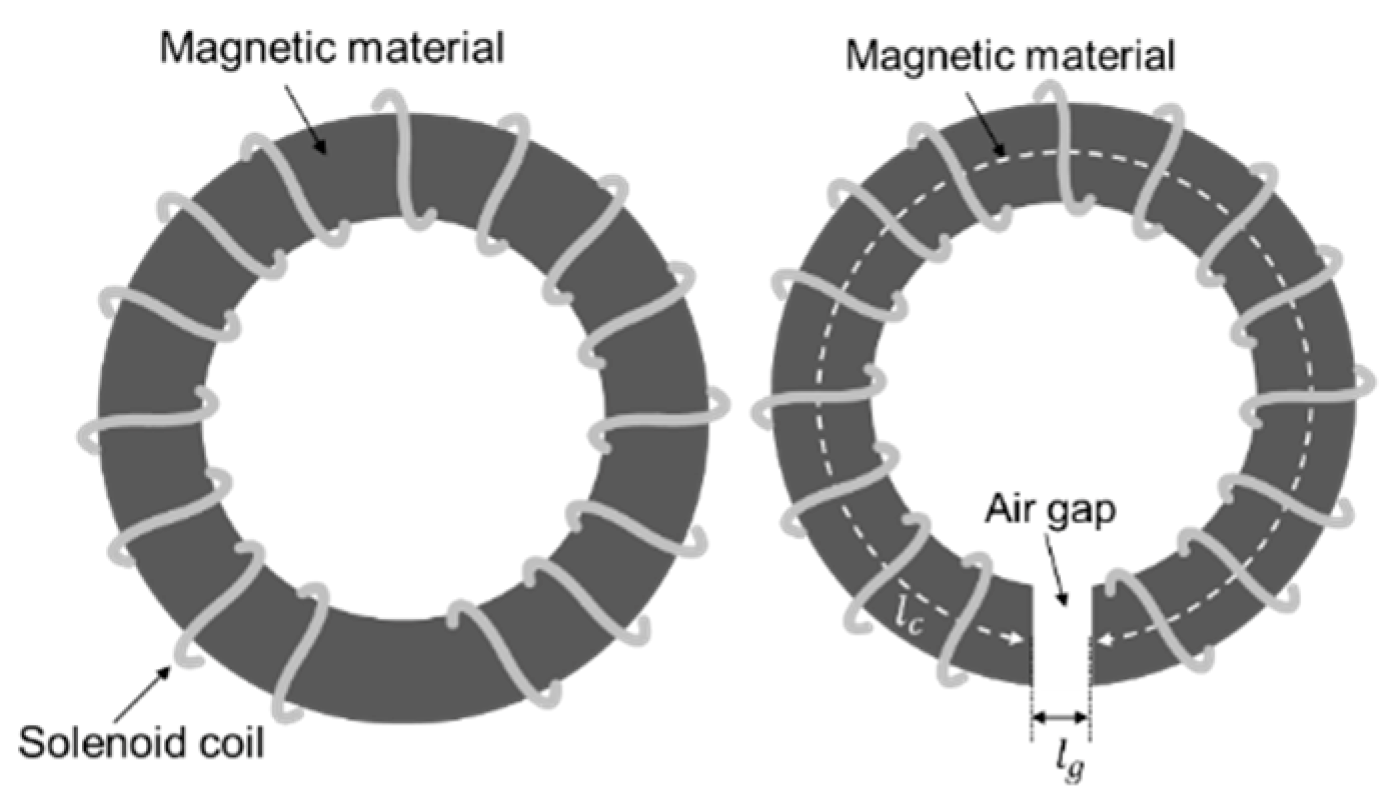
Figure 3 illustrates the air-gap between the magnetic materials. The magnetic field vectors pass through the magnetic material, and the hollow or air-gap between the magnetic materials causes a reduction in relative permeability. Hence, the effective permeability of the magnetic material can be derived using Equation (1) according to [
13].
where,
,
,
and
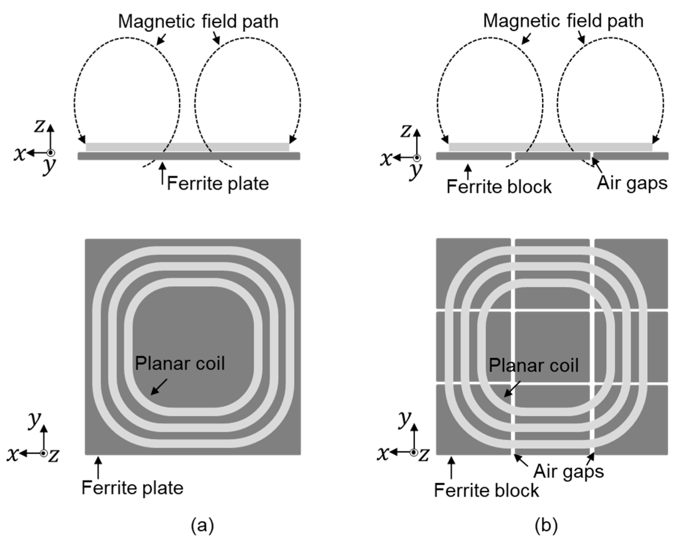
represent the effective permeability of the magnetic material, the permeability of the core, length of the gap, and mean magnetic path length of the magnetic material, respectively. Considering that the self-inductance of the coil and mutual inductance between the coils are proportional to the permeability, adding an air-gap decreases self-inductance as well as mutual inductance [
12]. In the case of a planar coil with a ferrite plate and ferrite blocks, the air-gaps between the discrete ferrite blocks lower the effective permeability, compared to the lumped ferrite plate model, as illustrated in
Figure 4.
Applying this concept to the WPT coils in SAE J2954 RP is reasonable since the dimensions of the ferrite blocks are not strictly described in the standard.
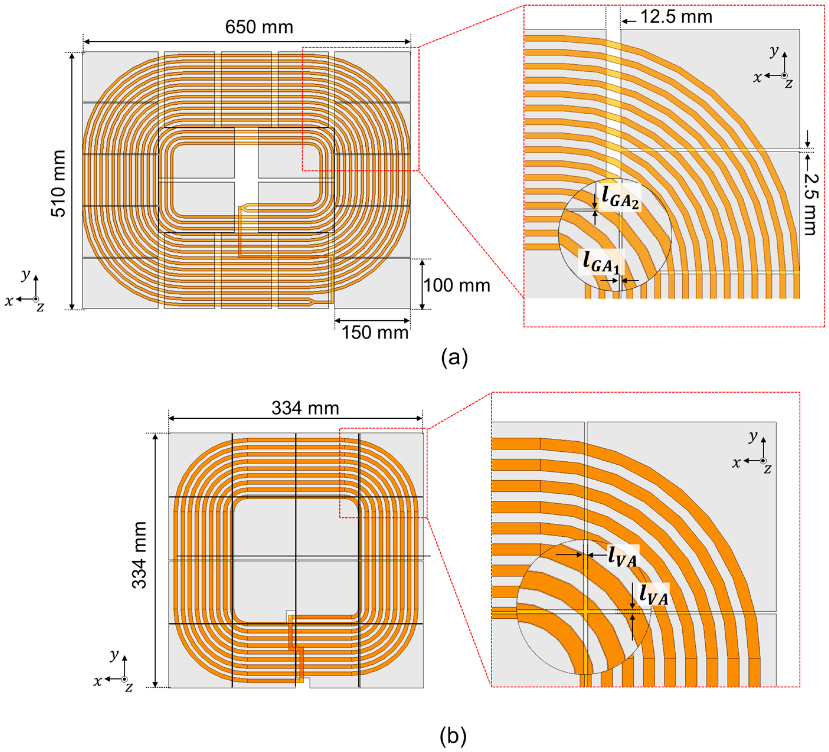
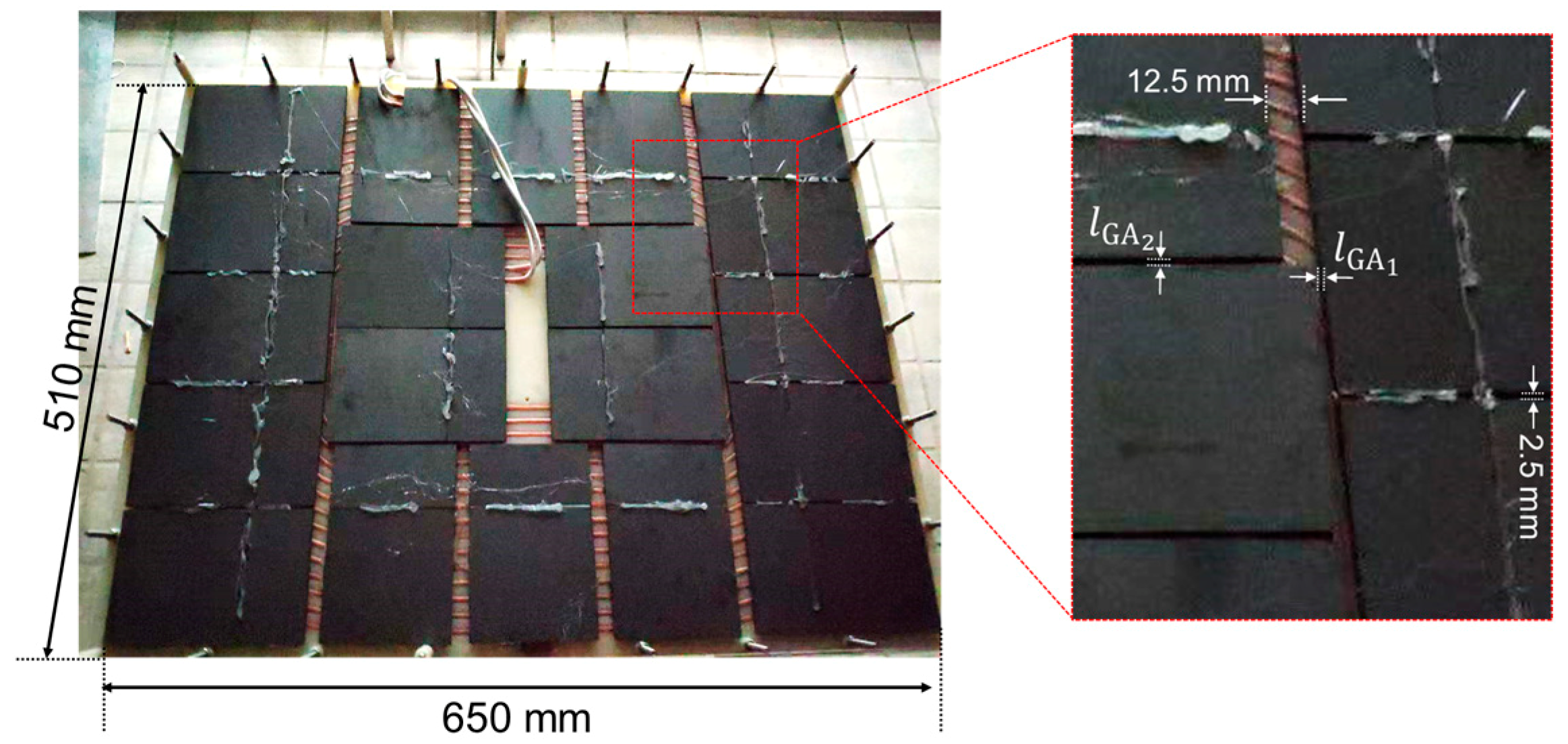
Figure 5 illustrates the dimensions of the ferrite arrangement on the GA coil. The boundary size of the GA ferrite blocks is 650 mm along the x-axis and 510 mm along the y-axis as described in
Figure 6a. Taking into account that the area of the ferrite blocks in the GA coil is 150 mm × 100 mm, and the ferrite blocks have even air-gaps, the gaps between the outer ferrite blocks can be calculated to be 12.5 mm and 2.5 mm, as described in
Figure 6b.
On the other hand, the air-gaps between the inner ferrite blocks and outer ferrite blocks are not clearly described. For this study, the gaps between the outer ferrite blocks and the inner ferrite blocks are designated and . The boundary size of the VA ferrite blocks is 334 mm along the x-axis and 334 mm along the y-axis. Because the VA coil has 4 × 4 ferrite tiles, if the air-gaps on the VA ferrite block () are assumed to be 0 mm, the length of each of the ferrite blocks will accordingly be 83.5 mm.
To verify the proposed method, a simulation was conducted and the results were compared to those obtained in advance from experiments. For the simulation, a 3D finite element method solver, ANSYS Electronics-Maxwell, was used.
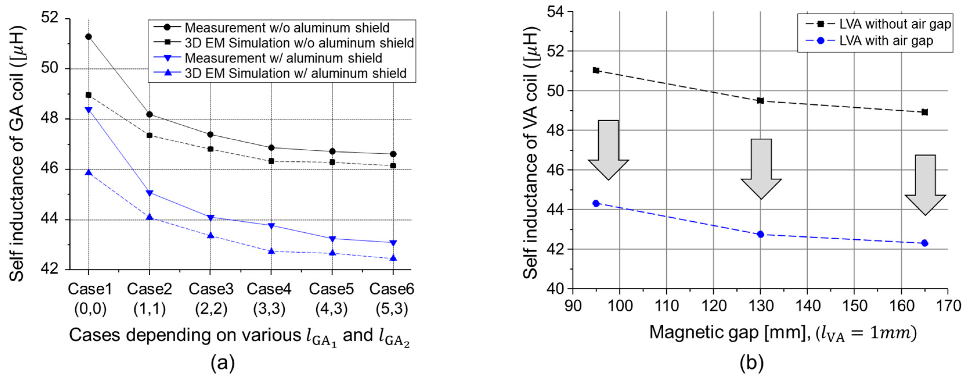
Figure 6a presents the L
GAs obtained by simulation, and by experimental measurement. The x-axis represents pairs of
and
with millimeter units, respectively. The black lines represent the self-inductance of the GA winding when the setup includes the GA ferrite and GA winding only. When the aluminum shield is applied in this setup, then the self-inductances are decreased, as shown by the blue line. As the
becomes larger, the self-inductance in both cases is decreased as well. The difference in simulation and measurement values had an error rate lower than 5%, which is reasonable considering likely measurement and calibration error.
Figure 6b shows the simulated self-inductance of the VA coil depending on the different magnetic gaps. The black solid points represent the self-inductance of the VA coil when the ferrite air-gap was zero. Even a small air-gap, 1-mm, results in a 10% L
GA reduction, which closely approaches the given range in the standard. These results confirm that controlling the air-gap between the ferrite blocks allows the self-inductance of the GA and VA coils to be controlled.
4. Determining the Air-Gaps between the Ferrite Blocks
To determine the specific
and
, to achieve the given range values of the L
GA, L
VA, and coupling coefficient, all dimensions were considered in this work. The designed dimensions strictly followed the given dimensions described in the SAE J2954 standard. For detailed modeling of GA and VA, both the GA and VA windings were drawn using the SolidWorks design tool as described in
Figure 7.
For the WPT2/Z2, the suggested range of ground clearance is 140 mm to 210 mm, and the maximum misalign values in the x-direction and y-direction are 75 mm and 100 mm, respectively.
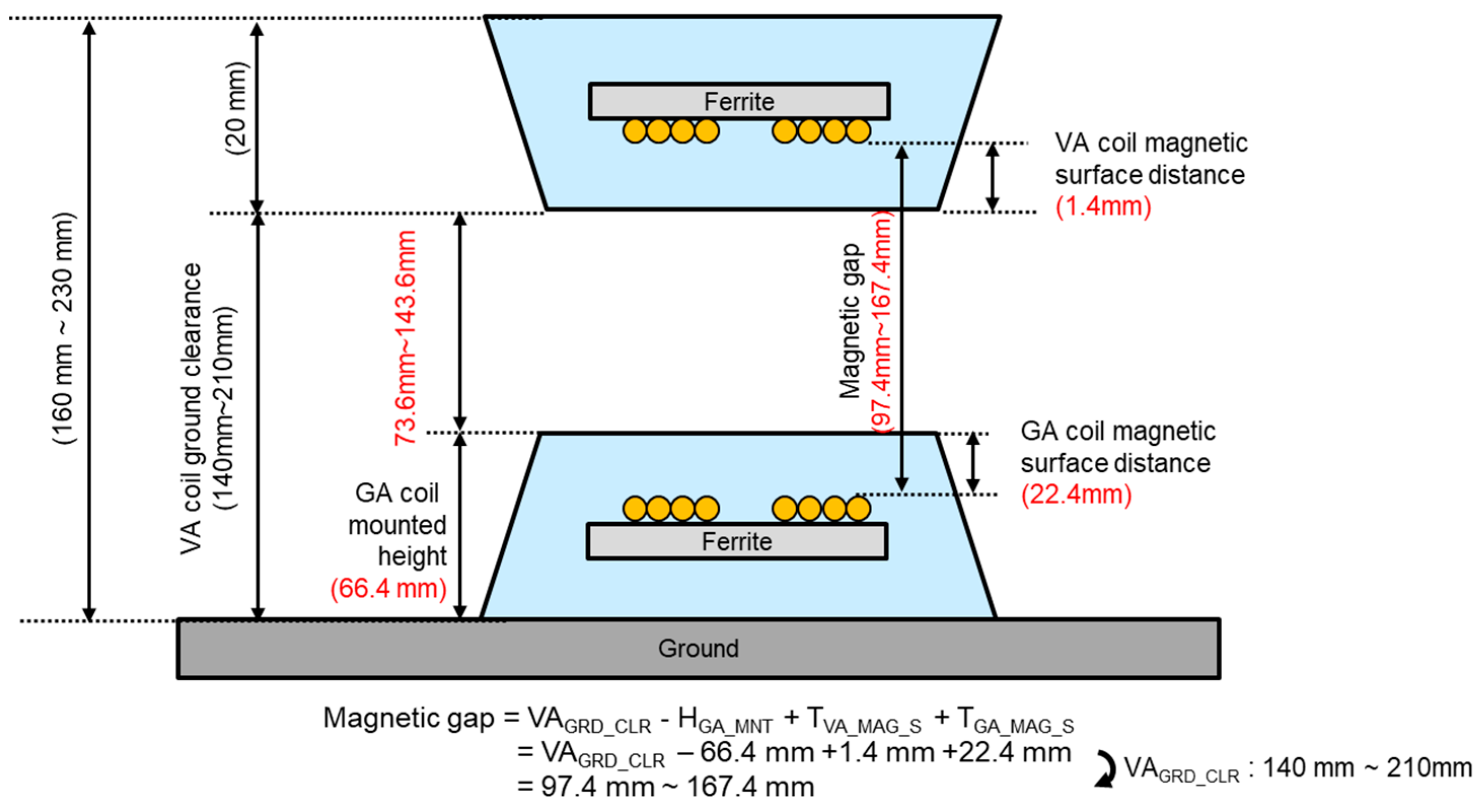
Figure 8 illustrates some parameters including magnetic surface, ground clearance, and magnetic gap of the standard. These parameters are significant as the magnetic gap affect to the self-inductance of GA and VA coils as well as coupling coefficient.
To reflect the GA/VA magnetic surface of the fabricated Litz tray, the distances between the magnetic surfaces of the GA/VA coils in the designed model were 22.4 mm and 1.4 mm, and the GA coil mounted height was 66.4 mm. Accordingly, the magnetic gap was derived from these values, resulting in 97.4 mm, 142.4 mm, and 167.4 mm minimum ground clearance, nominal ground clearance, and maximum ground clearance, respectively.
To reflect the 85 kHz powering condition, the simulation mode was set to the eddy current solution type. Considering that the excited magnetic flux density is up to 100 mT, the permeability of the commercial ferrite block was set to 3000 with reference to [
14]. Also, the manual mesh options are applied to the aluminum shield and steel plate to take into account the eddy current effect on the metal plates. We considered that the conductivity (
) and relative permeability (
) of aluminum and steel are 38,000,000 siemens/m, 5,180,000 siemens/m, 100, 1.001, respectively. Under the frequency
of 85 kHz, by
, the evaluated skin depths (
) are 0.2811 mm and 0.0758 mm, respectively. When it comes to the ferrite air gap on VA coil, based on the results in
Figure 6b, the
was constrained to 1 mm in this work.
To examine how the air-gaps between the ferrite blocks affected the LGA value, and were changed from 0 mm to 5 mm, and from 0 mm to 3 mm, respectively, to determine their value. The varied air-gap in the GA coil influenced not only the self-inductance of the GA coil, but also the VA coil. The coupling coefficient, the self-inductances of the GA/VA coils and the coupling coefficient were also observed.
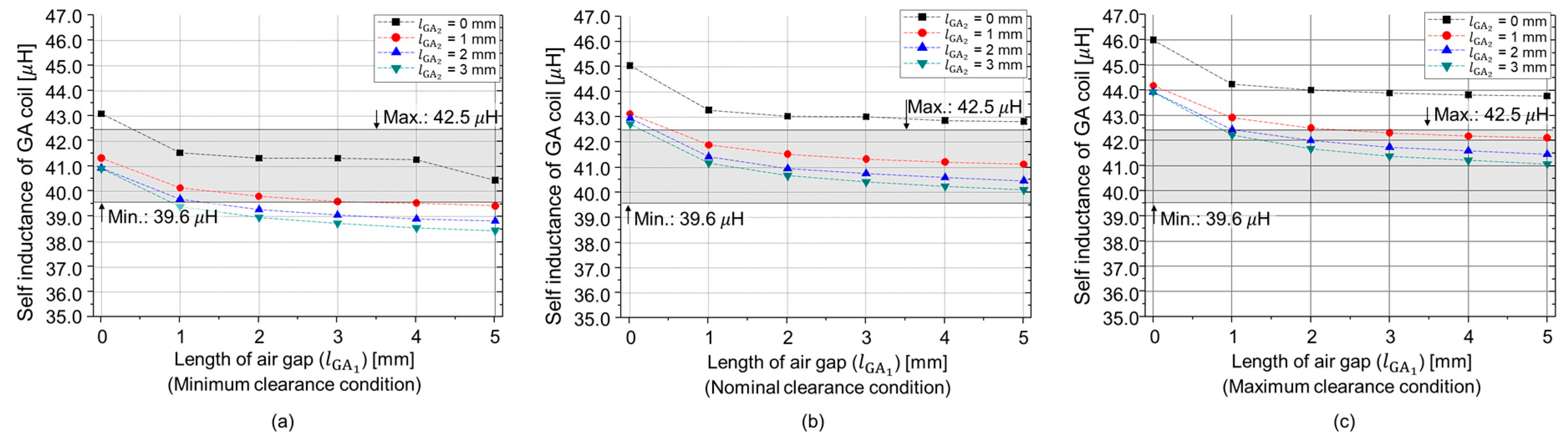
Figure 9 illustrates the self-inductance of the GA coil under the full-setup conditions, following the SAE J2954 standard. For the ferrite blocks without the air-gap, the self-inductance exceeded the given range in all ground clearance cases. However, the self-inductance of the GA coil decreased as the
and
increased, as previously discussed. The L
GA became larger as the ground clearance or magnetic gap increased, due to the lessening of the VA coil’s effect. Depending on the
and
changes, the L
GA changed by around 10%.
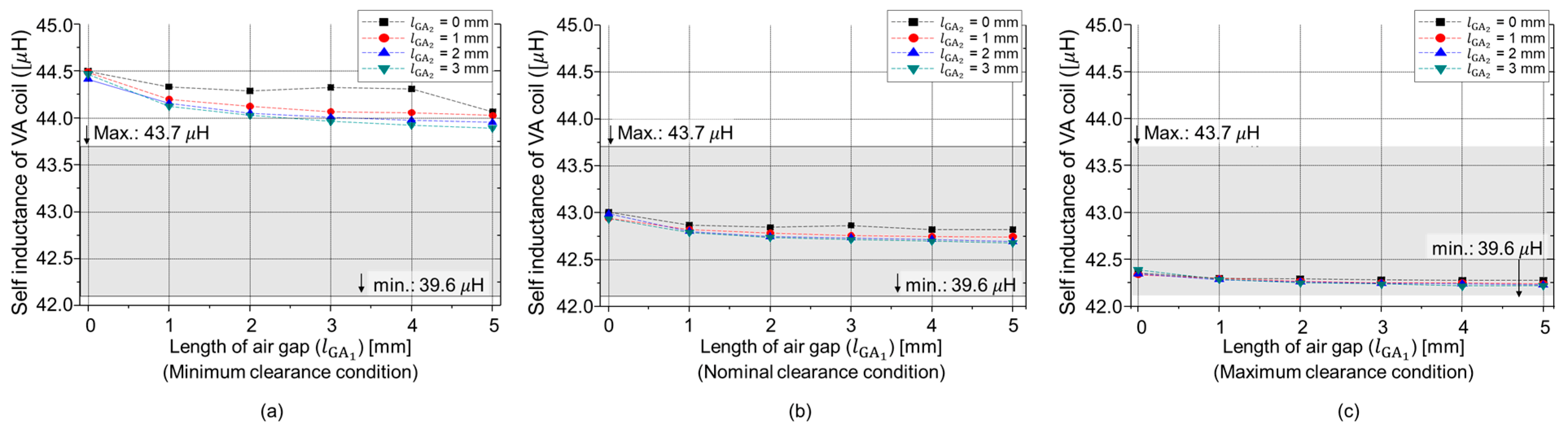
Figure 10 describes the self-inductance of the VA coil depending on the air-gap of
and
. The different effective permeability of the GA ferrite blocks also affected the self-inductance of the VA coil. For this reason, as the ground clearance increased, the variation in the L
VA values were negligible, because the effect of the GA coil decreased significantly, as illustrated in
Figure 10c. In the L
VA cases, the variation level was much lower compared to the L
GA case, achieving less than 1.5% variation.
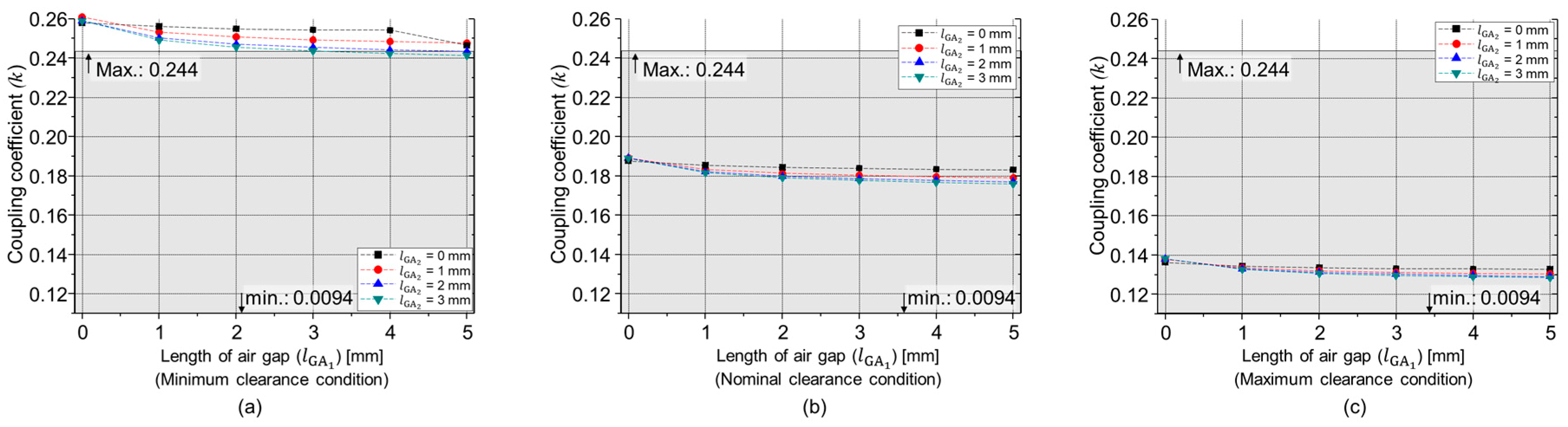
Figure 11 describes the self-inductance of the GA coil, the VA coil and the coupling coefficient (
k) between the two coils. As the effective permeability decreased, the coupling coefficient decreased. Taking into account the discussed electric parameters, the L
GA, L
VA, and coupling coefficient, the reasonable values of
and
were determined to be 1 mm and 1 mm, respectively.
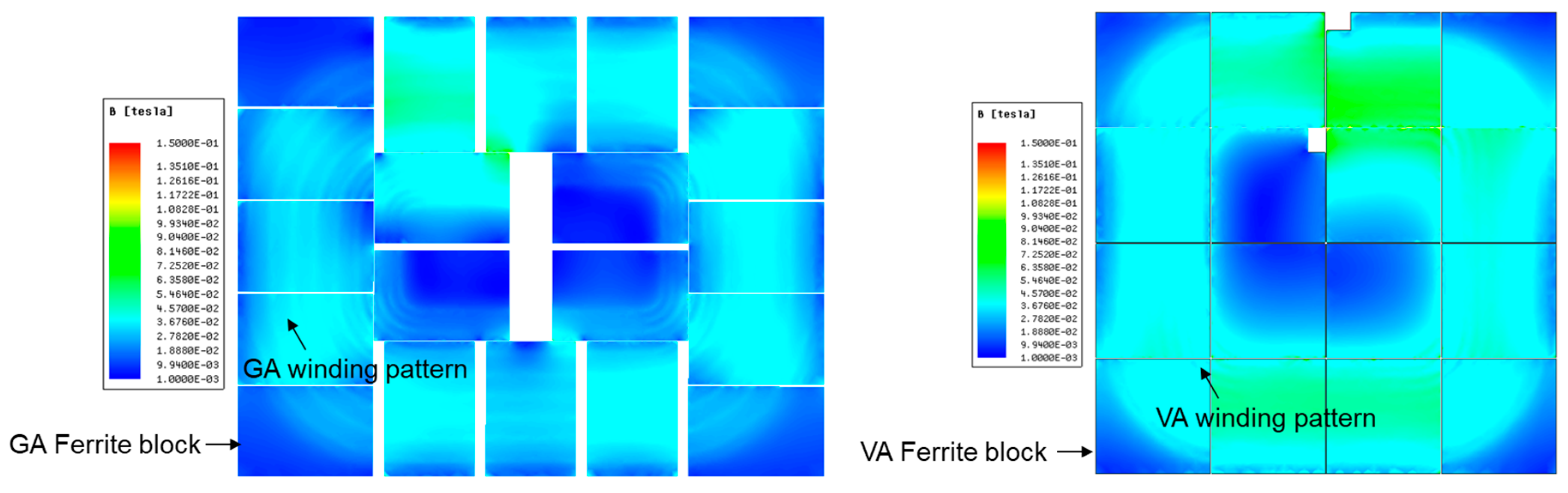
The saturation of the ferrite block was also verified by simulation, as the ferrite loses its magnetic properties when it is saturated. Practically, the current on the transmitting and receiving coils can be estimated up to 50 A-rms. In this condition, the magnetic flux from the GA is added to the magnetic flux from the VA. While this is the possible worst-case scenario in terms of current magnitudes, the phase between the magnetic fields from GA and VA was set to zero to check the possibility of ferrite saturation. For the ferrite blocks, the magnetic characteristic of TDK N95 was used as the ferrite properties, to reflect a practical model. As described in
Figure 12, the maximum magnetic field of 100 mT was observed near the coil wire region. Considering that the saturation point of ferrite is 350 mT, the proposed method is not expected to reach the saturation level [
14].
5. Experimental Verification
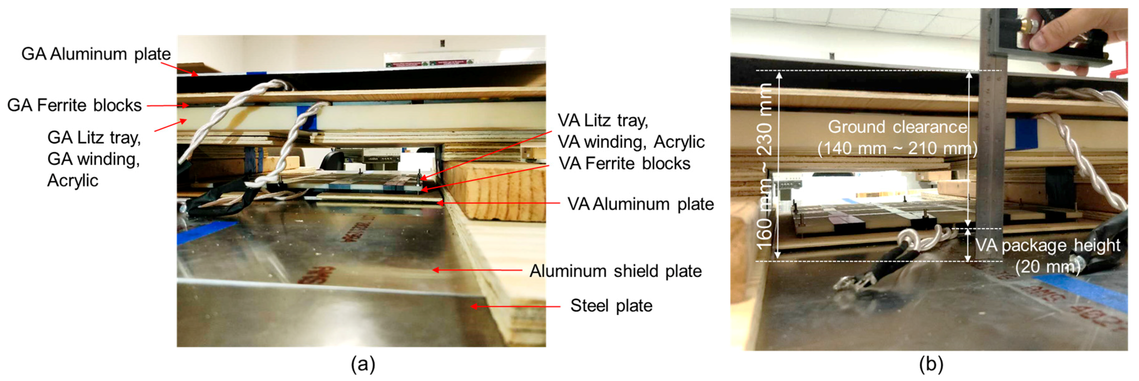
To verify the evaluated air-gap values, experiments were performed under the various ground clearance conditions. The experiment setup used to verify the proposed method is illustrated in
Figure 13. In this setup, the and
were varied from 0 mm to 5 mm, and 0 mm to 4 mm, respectively. The results of these values were previously introduced in
Section 3,
Figure 6a.
After confirming the proposed method was valid, we conducted an experiment with a full-setup to verify the determined values of and converged to 1 mm.
Figure 14 represents the whole system measurement setup for securing self-inductance of GA coil, VA coil and coupling coefficient between two coils. All the measurement was conducted following the test bench referred on standard dimension. The wood blocks were used for supporting the GA coils and to maintain the ground clearance refer to the standard, the measurement was strictly conducted as shown in
Figure 14b. The GA coil mounted height and magnetic coil surface distance were measured as 66.4 mm and 22.4 mm, respectively, while the VA coil magnetic surface distance was measured as 1.4 mm.
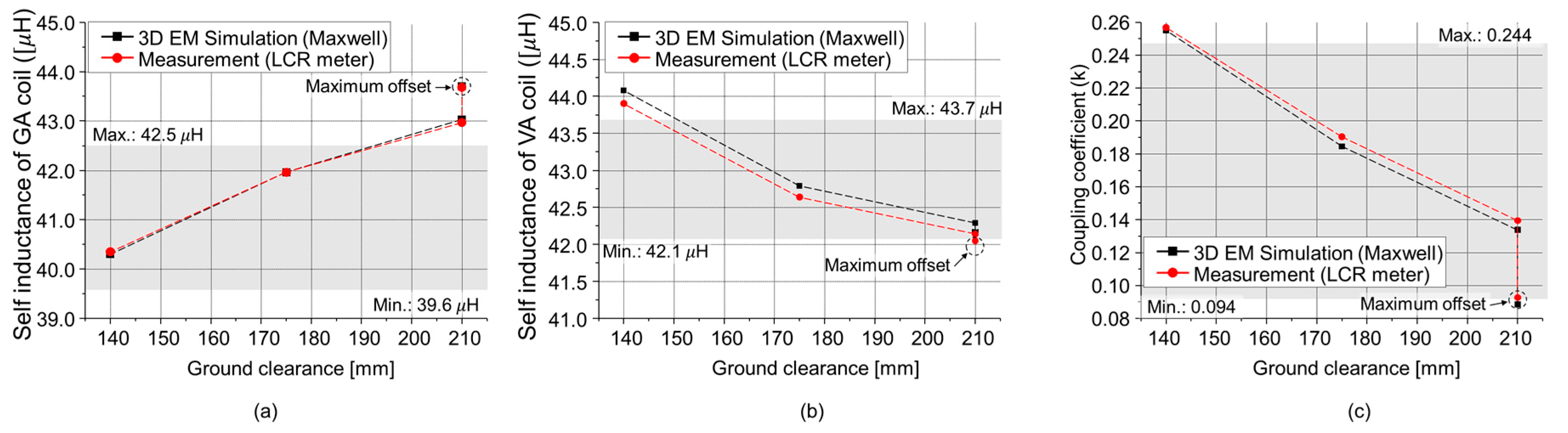
Figure 15 illustrates the simulated and measured self-inductance values of the GA coil, the VA coil and the coupling coefficient, including all clearances, as well as the maximum misalign condition (∆x = 75 mm, ∆y = 100 mm). Based on the simulated results, the
and
were set as 1 mm and 1 mm, respectively. For the measurement, a TH2827C LCR meter was used at 85 kHz. The errors between simulation and measurement were lower than 4.5%. The highest out of range given in the SAE J2954 standard for the self-inductance of the GA, VA and coupling coefficient were 0.5%, 2.8%, and 5.6%, respectively. Since the coupling coefficient is obtained by
, the out-of-range inductances produce a lower coupling coefficient.

 ,
, 


