Exergy and Exergoeconomic Analysis of a Combined Cooling, Heating, and Power System Based on Solar Thermal Biomass Gasification


School of Energy, Power and Mechanical Engineering, North China Electric Power University, Baoding 071003, China
*
Author to whom correspondence should be addressed.
Energies 2019, 12(12), 2418; https://doi.org/10.3390/en12122418
Submission received: 1 May 2019
/
Revised: 7 June 2019
/
Accepted: 21 June 2019
/
Published: 24 June 2019
(This article belongs to the Section F: Electrical Engineering)
Abstract
:The purpose of this paper is to improve the utilization of renewable energy by exergy and exergoeconomic analysis of the novel combined cooling, heating, and power (CCHP) system, which is based on solar thermal biomass gasification. The source of heat to assist biomass and steam gasification is the solar heat collected by a dish collector, and the product gas being fuel that drives the internal combustion engine to generate electricity and then to produce chilled/hot water by a waste heat unitization system. The analysis and calculation of the exergy loss and exergy efficiency of each component reveal the irreversibility in the heating and cooling conditions. Then, the exergoeconomic costs of multi-products such as electricity, chilled water, heating water, and domestic hot water are calculated by using the cost allocation method based on energy level. The influencing factors of the unit exergy cost of products are evaluated by sensitivity analysis, such as initial investment cost, biomass cost, service life, interest rate, and operating time coefficient. The results reveal that the internal combustion engine takes up 49.2% of the total exergy loss, and the most effective method of products cost allocation is the exergoeconomic method based on energy level and conforms to the principle of high energy level with high cost.
1. Introduction
Combined cooling, heating, and power (CCHP) systems are extensively considered to be a highly efficient distributed energy system that conforms to the energy cascade utilization to improve performance and mitigate energy and environmental problems. Clean or renewable energy technologies are largely integrated with CCHP systems to further improve energy sustainability development [1]. Biomass and solar energies resources, which belong to clean energy, have attracted extensive attention of the researchers due to their renewability and huge potential [2,3,4].
The advantage of the hybrid CCHP system based on the simple complementary method of biomass and solar energies is that the two kinds of energy can work independently in their respective equipment and not necessary to mix directly in the same equipment to react. For instance, the purpose of a solar vacuum collector in the biomass CCHP system is only to collect solar energy, which is used to compensate for the lack of heat in the absorption cooling and heating [5]. In addition, the process of biomass gasification also indirectly utilizes the solar energy, such as gasifying biomass into steam through the solar heat collectors [6,7]. Differently than the simple complementary, solar energy fuel needed by the CCHP system is obtained by the biomass gasification reaction of solar energy, which is commonly referred to as solar thermochemical utilization with the higher temperature of the solar. This complementary method has been demonstrated to be effective in converting biomass raw materials into syngas with the higher energy levels [8,9]. Biomass wastes from the rice paddy and the forest sector can generate 31.69 PJ and 222.37 PJ of energy annually by converting to bioethanol, accounting for 41.5% and 291.06% of the current level (76.4 PJ), respectively. In the action of gasifying agent, biomass is converted into syngas (H2 and CO), which is usually used to produce the energy and biofuels [10,11]. The analysis of the biomass gasification in concentrated solar supercritical water [12] shown that at the best design condition, the system-level carbon efficiency, energy efficiency, and exergy efficiency were 88%, 71%, and 45%, respectively. Based on the research of solar thermal biomass gasification, it is shown that the chemical energy converted by solar energy is equivalent to the increase of biomass heat value when the enthalpy of solar energy input reaction changes.
The performance analysis for an advanced and complex energy system is necessary to find the irreversibility and improve/optimize the cycle and parameters. In addition to the traditional methods just like energy, environmental, economic, and exergy analysis [13,14], several hybrid evaluation methods were employed to make the energy system achieve better performance in multiple aspects. It is impossible to provide exergy-based economic results from exergy analysis or economic analysis, but the exergy-based economic results can be obtained by the exergoeconomic analysis method which combines exergy and economic analysis. Exergy destructions [15] and exergy losses of system are used to evaluate the thermodynamic inefficiencies. The most serviceable way to increase the cost effectiveness of the system is to grasp the source of inefficiencies cost, which is very beneficial to reduce the production cost of the system. Some studies were to present a clearer picture of the main irreversibility and their corresponding costs and to find some effective alternatives to improve the efficiency and cost-effectiveness [16,17,18,19,20,21]. The application examples of this kind of multi-effect power plant include the combination of gas turbine cycle and pressurized water reactor power plant, and the combined cycle with co-firing of biomass and natural gas, which can improve the efficiency of the power plant [17,22]. The possible schemes in the studies of [23] and [22] were assessed and compared through the exergoeconomic analysis and the optimal systems were selected.
In exergoeconomic analysis, costing principles as auxiliary equations are necessary to allocate fuel and non-exergy costs to products when multiple product streams are generated by one control volume. In order to have a good evaluation index for economic cost, it is necessary to introduce exergy parameters. Usually the equal costing method in the fuel-product-loss principles [24] that the unit costs of all streams from one control volume are equal is commonly adopted to formulate the auxiliary equations [25,26]. However, it doesn’t consider their difference in energy levels of the products. Consequently, some modified methods were proposed to rationally allocate the cost of one control volume. For example, a splitting factors of the system components are defined and employed to allocate the cost in the study from Erlach et al. [27]. To achieve more satisfactory cost allocation results, the engineers need to be allowed to participate throughout the allocation process. Based on the difference of energy quality between import and export of different components, Peng et al. [28] advanced the method of calculating the unit exergy cost of combined cycle products by using the energy quality factor (EQF). A method of exergy cost allocation based on energy level (ECAEL) is proposed. This method explains the additional allocation equation and introduces the exergy cost in detail. The exergy cost obtained by the traditional method of exergy cost allocation is the same. In order to satisfy the results of high quality and high cost, the exergy cost allocation based on energy level is proposed as an improved exergoeconomic method. [23,29]. These modified allocation equations aim to make a reasonable price for the cost of products from the viewpoint of exergy, and then, the unit energy cost of final product market pricing is converted from the unit exergy cost [29].
The purpose of this paper is to present exergy and exergoeconomic analyses for the novel hybrid CCHP system integrated with solar thermal biomass gasification in our research team’s literature [30]. The contributions of present work are to present the exergy analyses including efficiencies and losses of each component to reveal the irreversibility in the cooling and heating operation modes, and to allocate the exergy cost to multi-products of the hybrid CCHP system using the exergoeconomic method based on energy level. Section 2 presents the composition of the proposed CCHP system and thermodynamic model. Section 3 presents the methodologies of exergy and exergoeconomic analyses. Section 4 presents the research results and investigates the sensitivity analysis. Section 5 presents the principal conclusions.
2. System Description and Modelling
2.1. System Description
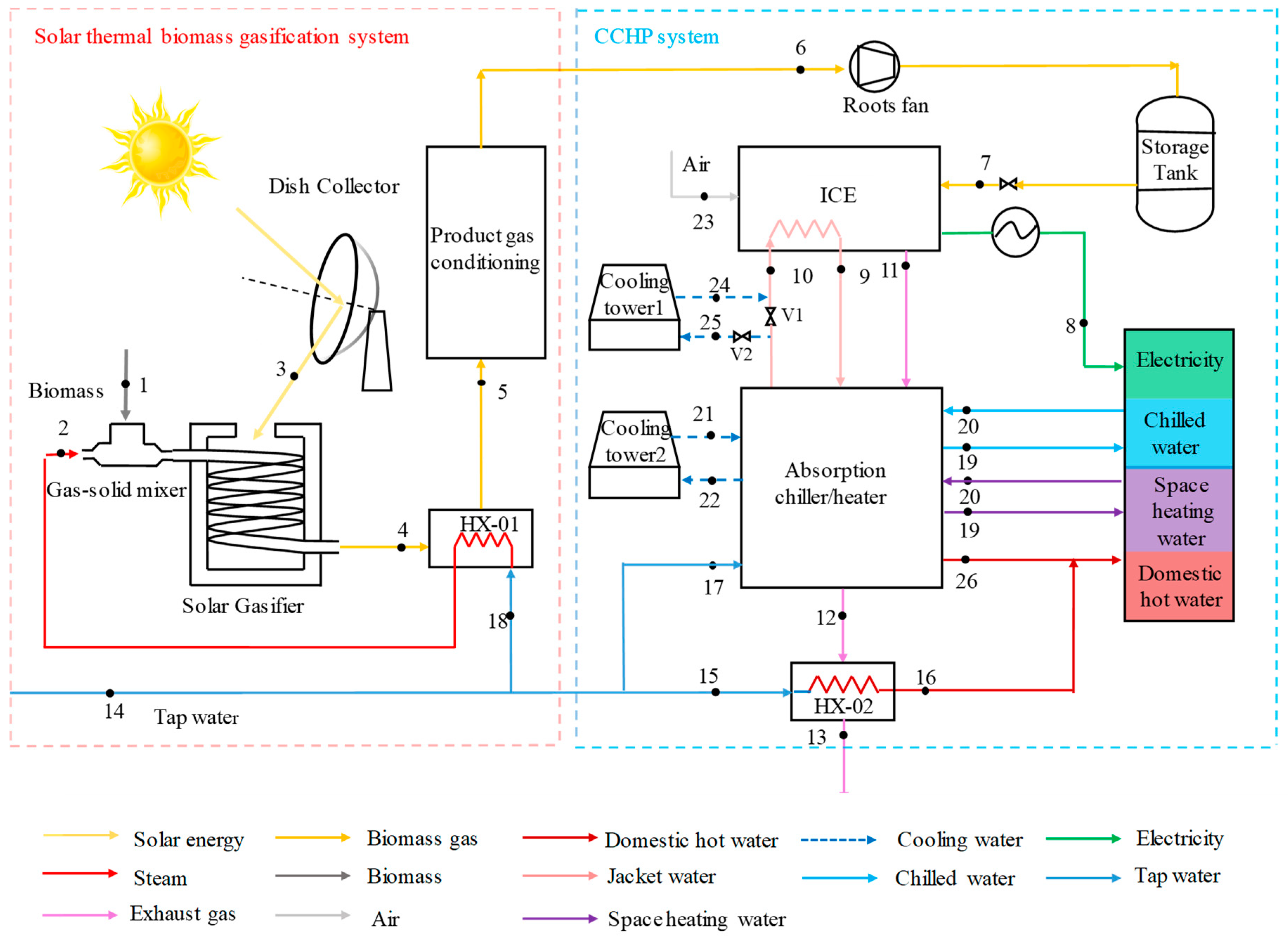
Figure 1 shows the novel hybrid CCHP system [30], in which chemical energy of syngas (H2 and CO) is converted from solar energy by solar thermal biomass gasification. It is divided into two subsystems: (1) the solar thermal biomass gasification system comprising solar dish collector, biomass gasifier, and product gas conditioning and (2) the CCHP system consisting of a storage tank, internal combustion engine (ICE), and absorption chiller/heater (AC/H).
Biomass (state 1) with steam (state 2) is decomposed into syngas (state 4) through the solar gasifier that is assisted by the concentrated solar dish collector (state 3) (The detailed information on solar gasifier can be referred in [30]). The heat exchanger (HX01) is used to cool the high temperature product gas (state 4), which is purified by the gas conditioning (state 6) to be sent to the ICE (state 7) to generate electricity (state 8). The heat released can generate biomass gasification steam (state 2) through the HX01. After power generation of ICE, the higher temperature exhaust gas (state 11) and jacket water (states 9 and 10) discharged from ICE is fed to AH/C to generate hot water for space heating (states 19 and 20) in the heating mode or chilled water for air conditioning (states 19 and 20) in the cooling mode and domestic hot water (state 26) in transmission seasons. After the cooling or heating of AC/H, the exhaust gas temperature (state 12) is relatively high and it continues to enter heat exchanger HX-02 to manufacture domestic hot water (state 16). The HX-02 is also considered a storage tank for domestic hot water. Furthermore, the excess syngas stored in tank supplement the shortage when the solar energy is unavailable. The operation modes and energy flows are described in detail in our research team’s literature [30]. Table 1 shows the basic design parameters.
2.2. Thermodynamic Models
The model has been simulated by Engineering Equation Solver [31], and the following assumptions were considered for the overall system simulation:
- (1)
- It is assumed that the system is based on the steady state.
- (2)
- The pressure descends of the whole heat exchangers and pipeline can be neglected.
- (3)
- In the heat transfer models, all heat exchangers are considered to be countercurrent heat transfer.
- (4)
- In the AC/H model, it is assumed that the steam, water, and solution at the outlet of evaporator, condenser, absorber, and high and low pressure generator are all saturated.
- (5)
- In the heat transfer model of the solar dish collector, the heat exchange in the inner wall of the component is heat conduction, and the heat exchange between the component and the surrounding environment includes convection heat transfer and radiation heat transfer.
Under the steady conditions, the mass, solution, and energy conservation of components are specified as follows [32]:
where the subscripts in and out represent inlet and outlet control quantities, respectively; is the mass flow (kg/s); is the concentration; and is the specific enthalpy (kJ/kg); and account, respectively, for the net rates of energy transfer by heat and work (kW). The main energy principles of the components are gathered in Table 2.
3. Methodology
3.1. Exergy Analysis
Exergy analysis is a very representative analysis method, which can be used to study various energy conversion processes, and can be used to explain the causes of irreversible energy loss during energy transfer and to have a more intuitive understanding of the exergy loss rate in the system [33]. The reference state of exergy analysis is at 25 °C and 1 atmospheric pressure. The exergy conservation is expressed as follows [35]:
where represents the specific exergy (kJ/kg); represents the exergy flow rate (kW); and , , and represent the exergy related to heat transfer, exergy associated with mechanical power and exergy destruction, respectively (kW). The specific exergy consists of physical and chemical exergy, which is defined as [5,34]:
where is the specific entropy (kJ/(kg·K)), is the temperature (K), is the molar ratio and is the universal gas constant (8.314 kJ/(kmol·K)). The subscripts ph and ch represent physical and chemical states, respectively, and the subscript 0 represents the reference state. The input exergy of solar energy and biomass exergy are expressed to, respectively:
where LHV is the low heat value (MJ/Nm3), Z is the mass percentage. The subscript sol represents solar energy, the subscript bio represents biomass, the subscripts moi and ash represent moisture and ash, respectively, and the subscripts C, H, O, and N represent carbon, hydrogen, oxygen and nitrogen, respectively. is the exergy ratio of total energy of solar radiation, and it is 0.9171 herein [36]. The factor is the ratio of the chemical exergy to the LHV of the organic fraction of biomass [37]. The mass percentage of each component of wheat straw is shown in Table 3, where V, FC, A, M and S are the volatile, fixed carbon, ash, moisture, and sulfur, respectively. The exergy of heat energy () is written to:
The exergy efficiency of a component, , is expressed to:
where is the product, and is the fuel.
3.2. Exergoeconomic Analysis
The exergoeconomic analysis method which combines exergy analysis with economic investigation is to show the process of exergy cost determination and to allocate multi-product costs from a hybrid CCHP system. Exergoeconomic analysis is applicable to the market pricing strategy for production plant supplies and to investment decisions and feasibility studies [19,23]. The hourly exergy cost balance of a system or component is written as [38,39]:
where , is the unit exergy cost ($/kWh); is the exergy cost ($/h). represents the levelized capital cost that is related to factors such as service life, interest rate and annual operating time ($/h). It mainly consists of the levelized investment and the maintenance cost and they are estimated as:
where is the initial investment of unit ($), represents the annual operating hours (h), is the coefficient of the maintenance cost to the initial investment cost, is the capital recovery coefficient, is the annual interest rate, and is the service life (year).
Costing principles as auxiliary equations are necessary to allocate fuel and non-exergy costs to products when multiple product streams are generated by one control volume. Considering the energy level differences of multiple products from one component, the exergy-based unit cost of any stream is directly proportional to its energy level, A, conform to the principle of higher energy level products having higher cost [19]. The energy level is defined to:
where is the exergy change of the process (kJ), is the enthalpy change (kJ), is the entropy change (kJ/K), and .
According to the cost balance equation and the costing principles of fuel-product based on energy level, the following equations for components are obtained.
Solar heat collector (SHC):
Gasifier (G):
Heat exchanger (HX-01):
Gas condition (GC):
Storage tank (ST):
Internal combustion engine (ICE):
Absorption chiller/heater (AC/H):
Heat exchanger (HX-02):
where is the exergy cost ($/h), is the investment cost ($), is the energy level, and are the unit price ($/kg) and mass flow rate (kg/s) of biomass, respectively. , and are the tap water unit prices ($/kg) at points 18, 17 and 15, respectively, and , and are expressed as mass flows rate (kg/s) of points 18, 17 and 15, respectively. It is noted that the streams from the cooling tower (states 21 and 22) in the heating mode don’t operate, the cost of cooling water is assumed to zero in the cooling mode and the investment cost of cooling tower is included into the cost of AC/H.
The exergoeconomic factor () is the ratio of initial investment to operation and maintenance cost, which measures the impact on the system. The value of exergoeconomic factor is proportional to its influence on the system, that is, the greater the ratio, the greater the impact on the system [21]. It is calculated as follows:
where is the cost of the exergy loss of part ($/h).
4. Results and Discussion
4.1. Initialization
The fuel used in the CCHP system is the wheat straw. Its specific composition is shown in Table 3 above and the electricity capacity of ICE is 100 kW. [30]. The thermodynamic performance simulations of the CCHP system were based on the Engineering Equation Solver (EES) software for exergy analysis. At the sizing of ICE, the cooling and heating energies from AC/H are 101.10 kW and 88.69 kW, respectively. The domestic hot water from the HX-02 is approximately 7.61 kW. Then, the economic parameters for exergeconomic analysis are listed into Table 4.
4.2. Results
4.2.1. Exergy Performances
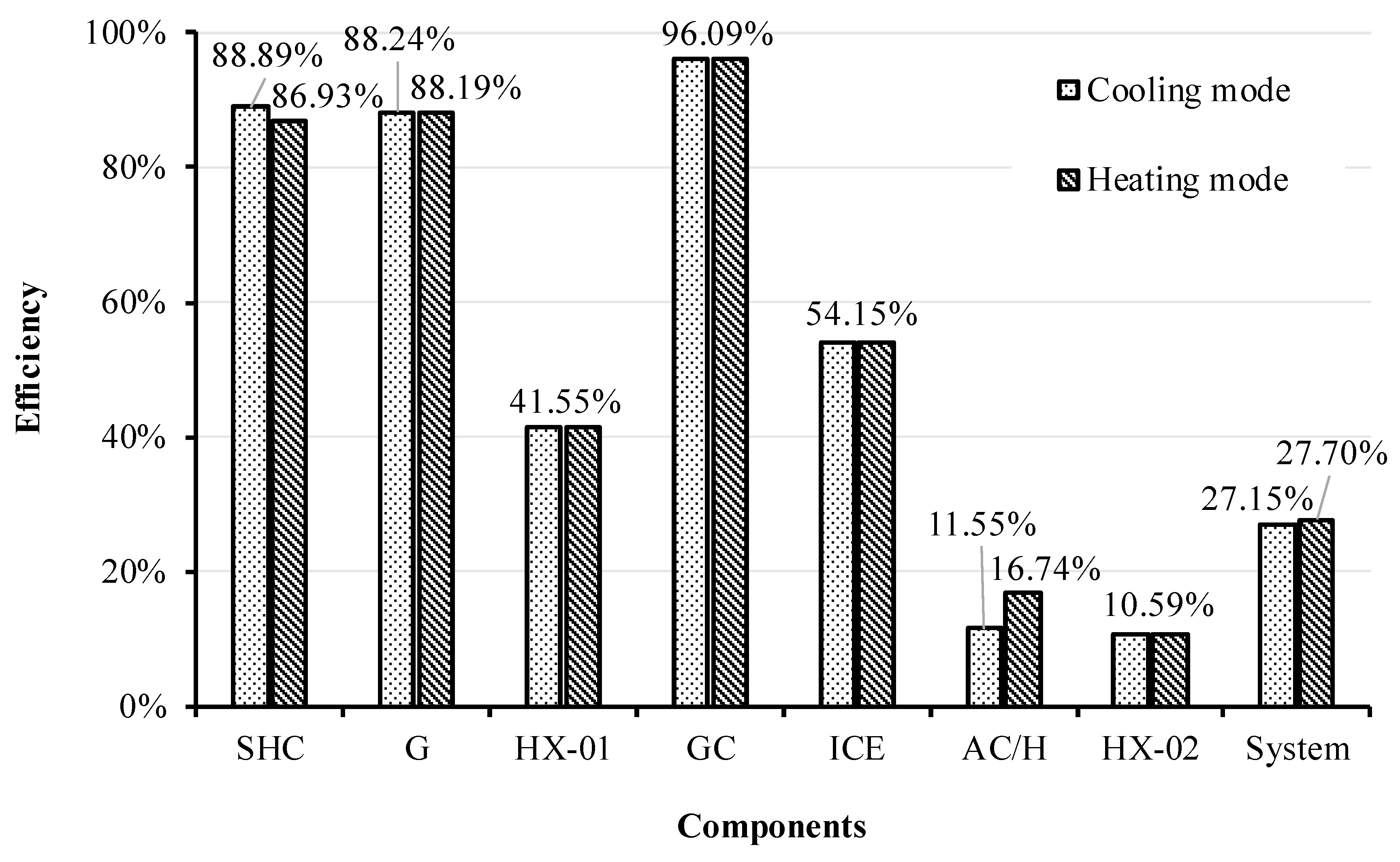
Figure 2 demonstrates the exergy efficiency of components. The exergy efficiency of the hybrid power system is 27.15% and 27.70% under the design conditions of the cooling and heating modes, respectively. The energy efficiency of the two modes are 58.74% and 53.16%, respectively. The reason why the energy efficiency of AC/H is higher in the cooling mode is that its cooling coefficient is higher. However, the exergy efficiency of AC/H in the cooling mode is lower than that in the heating mode, which is due to the lower temperature of the chilled water used in the cooling mode. From Figure 2, it is clear that HX-02 has the lowest exergy efficiency, which resulted from the larger temperature difference between the exhaust gas and hot water of HX-02. The second lowest exergy efficiency occurs in the AC/H and its exergy efficiency in the cooling mode is lower than in the heating mode. This is owing to the irreversible loss result of the low temperature of the chilled water or hot water, and the exergy of hot water is larger than the chilled water. The exergy efficiencies of HX-01, HX-02, GC, and ICE in the cooling mode are as same as their efficiencies in the heating mode, respectively. The difference in two operation modes of SHC and gasification mainly comes from the different solar radiation intensity. The collection efficiency of SHC and gasification efficiency are slightly lower in the heating mode than in the cooling mode, which is due to the lower solar radiation intensity in winter than in summer.
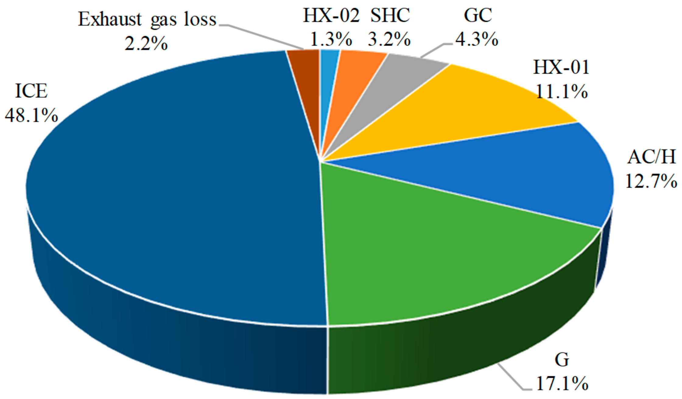
The comparisons indicated that the difference of each component in the two kinds of operation modes is slight. The average exergy destruction and loss of each component in the two operation modes are displayed in Figure 3. Herein, the exergy loss of exhaust gas from the HX-02 exiting to ambient is included, which accounts for about 2.2% of total exergy destruction and loss. It is clear that ICE is the component with the greatest exergy loss in the whole system, accounting for 48.1% of the total exergy loss, although the fact that the absorption chiller/heater have recycled high-temperature exhaust gas and jacket water of ICE. Its exergy destruction mainly come from the irreversibility of the combustion of natural gas. The second largest exergy loss component is the gasifier. The loss rates average 17.1%. The components with the minimal exergy destruction are HX-02 with 1.3% and SHC with 3.2%. The HX-02 is located at the end of energy cascade utilization, which accounts for the lowest exergy destruction. The SHC with higher exergy efficiency leads to the lower exergy destruction without the consideration of excess collected heat in the summer. The results show that the exergy efficiency of ICE and gasifier components can be improved as much as possible, which is helpful to improve the performance of the whole system.
4.2.2. Exergoeconomic Performances
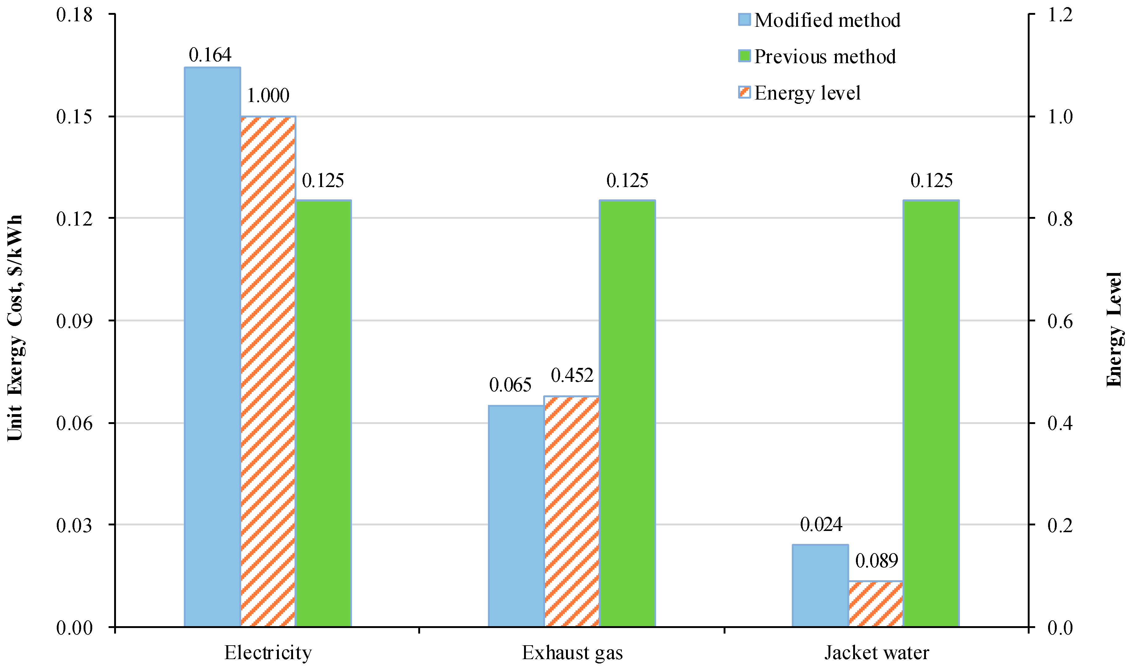
To validate the modified method of exergoeconomic analysis based on energy level in this paper, Figure 4 shows the comparison between the modified method and the previous method (The unit exergy cost of streams from one control volume is same and it doesn’t consider energy level of different streams) of the products of ICE.
It is observed that the unit exergy cost of the three products is the same, 0.125 $/kWh, using the previous cost calculation method, which doesn’t distinguish the difference between them from energy quality. Taking energy level of product consideration into the cost allocation, the highest energy level of the three products is electricity, 1.000, while the jacket water with the temperature of 85/70 °C is the lowest energy level, 0.089. Due to the energy level of electricity is the highest and the loss is relatively small, the exergy cost will naturally be higher than that of the previous method. However, the loss of jacket water and exhaust gas with the lower energy level is obviously larger than that of the electricity, and the corresponding exergy cost is also lower than that of the previous method. The modified method of the unit exergy cost of electricity increases by about 31.2% compared with the previous method, while the unit exergy cost of exhaust gas and jacket water decreased by 48.0% and 80.8%, respectively. The unit exergy cost of electricity, exhaust gas and jacket water is 0.164 $/kWh, 0.065 $/kWh, and 0.024 $/kWh, respectively. The highest unit exergy cost is electricity. The exergy cost allocation principle based on the modified method conforms to the expectation of high energy level and high cost, which indicates a feasible and rational way to allocate cost.
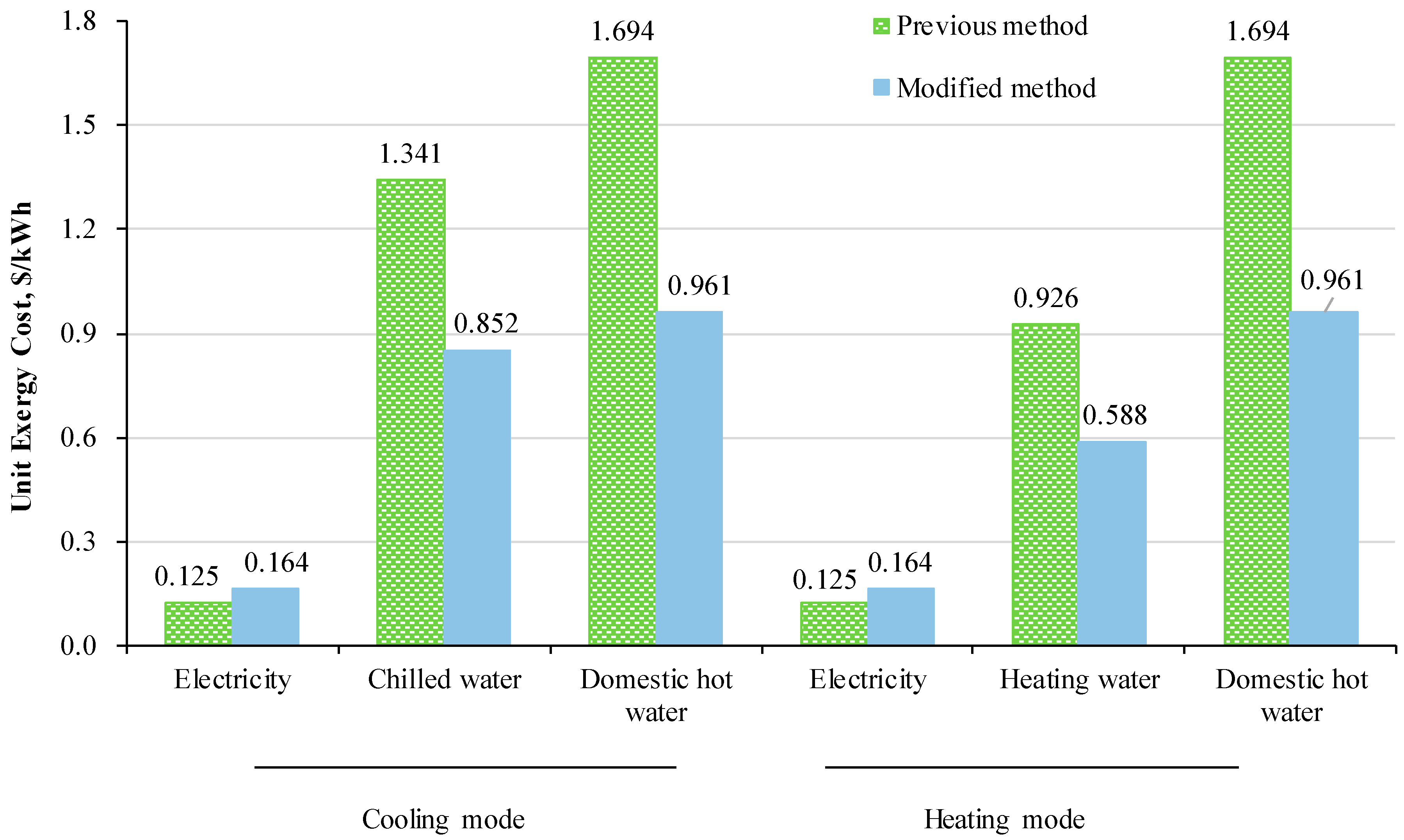
The unit energy and exergy cost of the product in the two operating modes of the hybrid CCHP system are shown in Table 5. It is seen that the cost of domestic hot water is the highest because it includes the cost of tap water while the cost of chilled water or heating water just the cost of cold and heat exergy, not water cost. The exergy cost of chilled water, 0.852 $/kWh, is larger than the exergy cost of heating water, 0.588 $/kWh. However, the energy cost of heating water exceeds the cost of chilled water when their exergy is transferred into energy.
Similarly, Figure 5 shows the comparison between the previous method and the modified method of the unit exergy cost of product in the two operation modes. The intuitive result is that the unit exergy cost of electricity based on the modified method is higher than before. While the unit exergy cost of products of the modified method is lower than before, which are chilled water/heating water and domestic hot water. The reason is that the energy level of electricity is the highest and the loss is the smallest, so the unit exergy cost of electricity will be higher than that of previous methods. However, the other products with the lower energy level will cause more losses than electricity, which will naturally lead to lower exergy costs than before. By calculating the difference of the unit exergy cost in the two methods, the electricity, chilled water, heating water, and domestic hot water are 0.039, 0.489, 0.338, and 0.733 $/kWh, respectively. The modified method shows that the exergy cost ratio of the electricity, chilled water, and domestic hot water is 1: 5.2: 5.9 in the cooling mode, and that of the electricity, heating water and domestic hot water is 1: 3.6: 5.9 in the heating mode, which is helpful to guide the pricing of products in the market.
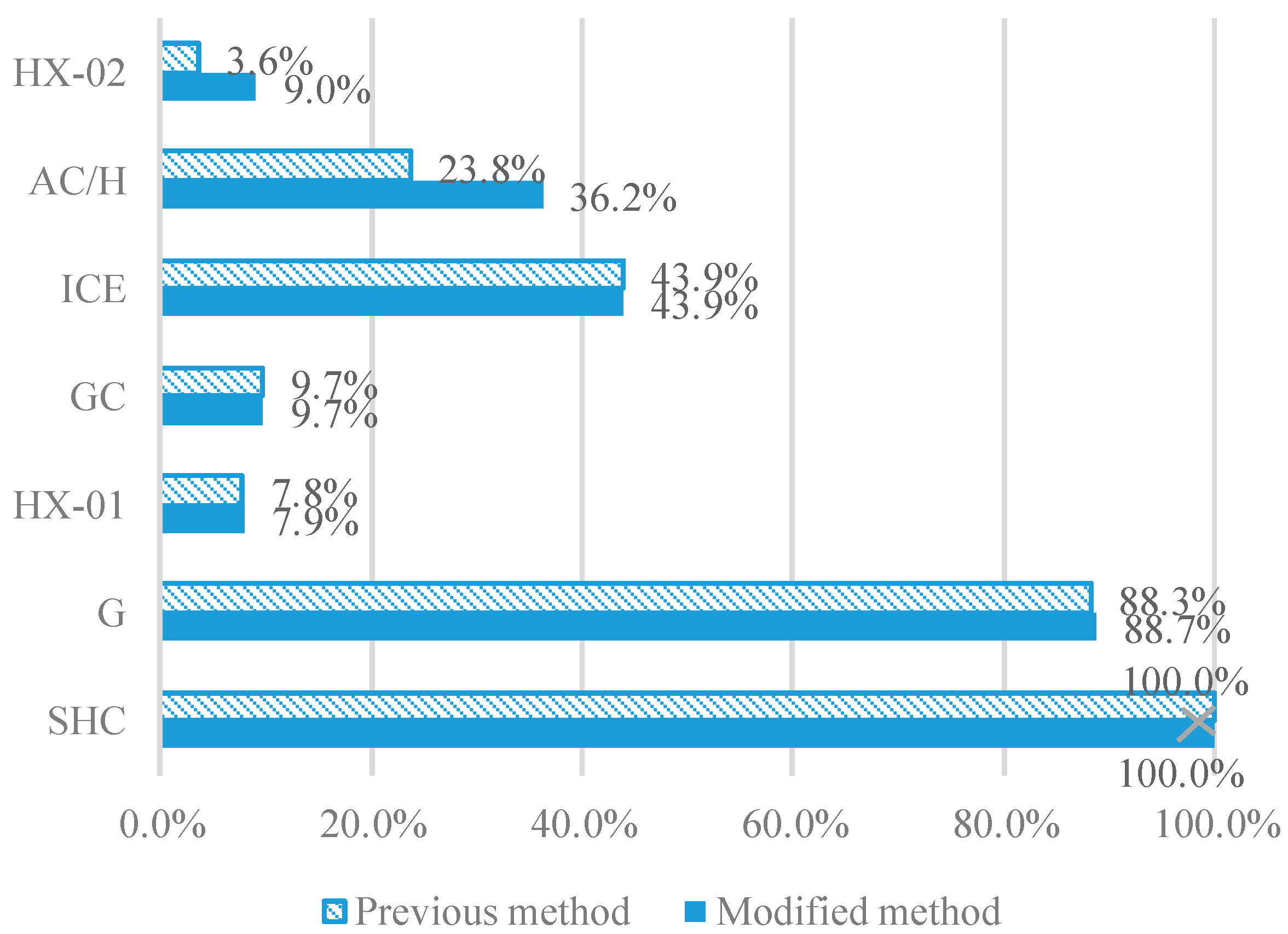
The exergoeconomic factors of components calculating in two methods are shown in Figure 6. Comparing the two methods, their corresponding exergoeconomic factors of SHC, GC, and ICE are same because of their single input stream, whose cost is same using two methods. However, the factors of HX-01, HX-02, AC/H, and G are not same and the factors in the modified method are larger than in the previous method, which result from the decrease of unit cost of input stream of each component because most investment cost is allocated by the electricity with the highest energy level. Analyzing the exergoeconomic factors in the modified method, the exergoeconomic factor of SHC is 100% because the solar energy inputting in SHC is free and the destroyed exergy cost of SHC equals to zero. Then, the gasifier has the largest exergoeconomic factor of 88.7%, which is due to the larger investment capital. The ICE and AC/H have similar exergoeconomic factors, approximately 40%. The exergoeconomic factor of HX is the smallest that is lower than 10%.
4.3. Sensitivity Analysis
The fluctuation of the unit exergy cost of the product caused by the change of key parameters can be clearly and intuitively seen by sensitivity analysis. The key parameters include initial investment cost, biomass cost, service life, and interest rate, and operating time coefficient. Because there are similarities of three products in the cooling and heating mode affected by factors, the following section is just to analyze the impacts of key factors on the unit exergy cost of electricity in the cooling mode.
(1) Investment Cost of SHC and Gasification System
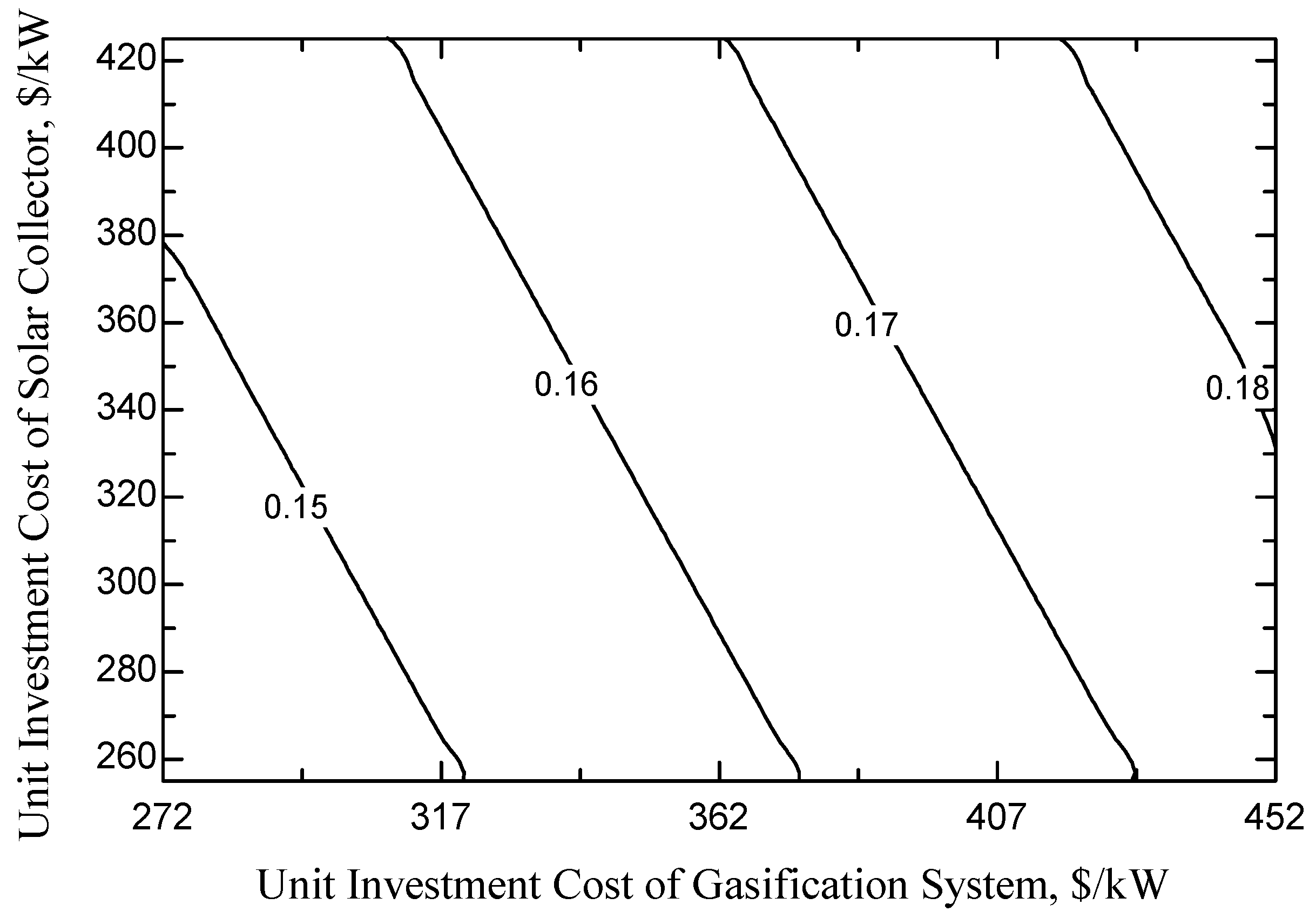
When investigating the influence of the investment cost of SHC and the gasification system, which decreases from −25% to 25% on the basic of design parameters, on the unit cost of products, other parameters are set to the design values. Figure 7 shows the variations of unit exergy cost of electricity with the unit investment cost of SHC and gasification system. Both the unit exergy cost of electricity increases linearly with the increase of the unit investment cost of SHC and the gasification system. When they increase 5%, the cost of electricity will increase 0.8% and 2.1%, respectively. It is obvious that the investment cost of gasification system has a greater impact, indicating that the decrease of investment of gasification system is more helpful to decrease the cost of products in the future technology developments.
(2) Biomass Cost
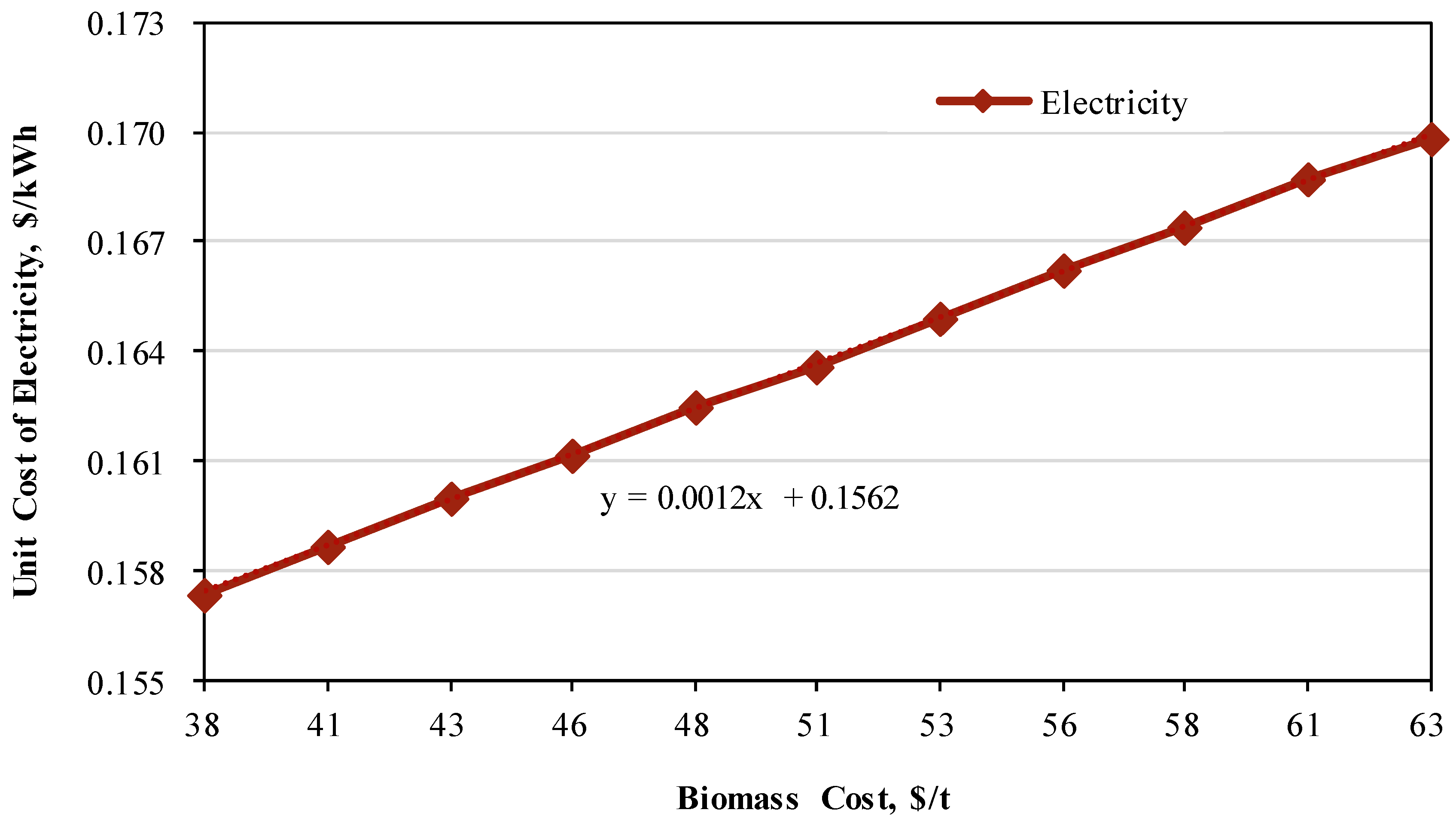
Similarly, when studying the fluctuation of the unit exergy cost of products caused by the change of biomass cost, which decreases from −25% to 25% based on the design parameters, other parameters are set to the design values. Figure 8 shows the variations of unit exergy cost of electricity with the increasing biomass cost. With the increase of biomass cost, the unit exergy cost of electricity also increases. When the biomass cost increased from 38 $/kWh to 63 $/kWh, the unit exergy cost of electricity increased by 7.91%. When the biomass cost increases 5%, the electricity cost will raise 0.0012 $/kWh. Compared to the influence of investment cost of gasification system in Figure 7, the variations of the biomass cost is less sensitive to the unit exergy cost of electricity at the same increasing/decreasing percentage. The decrease of investment of gasification system of 5% make the electricity cost decline 0.003 $/kWh.
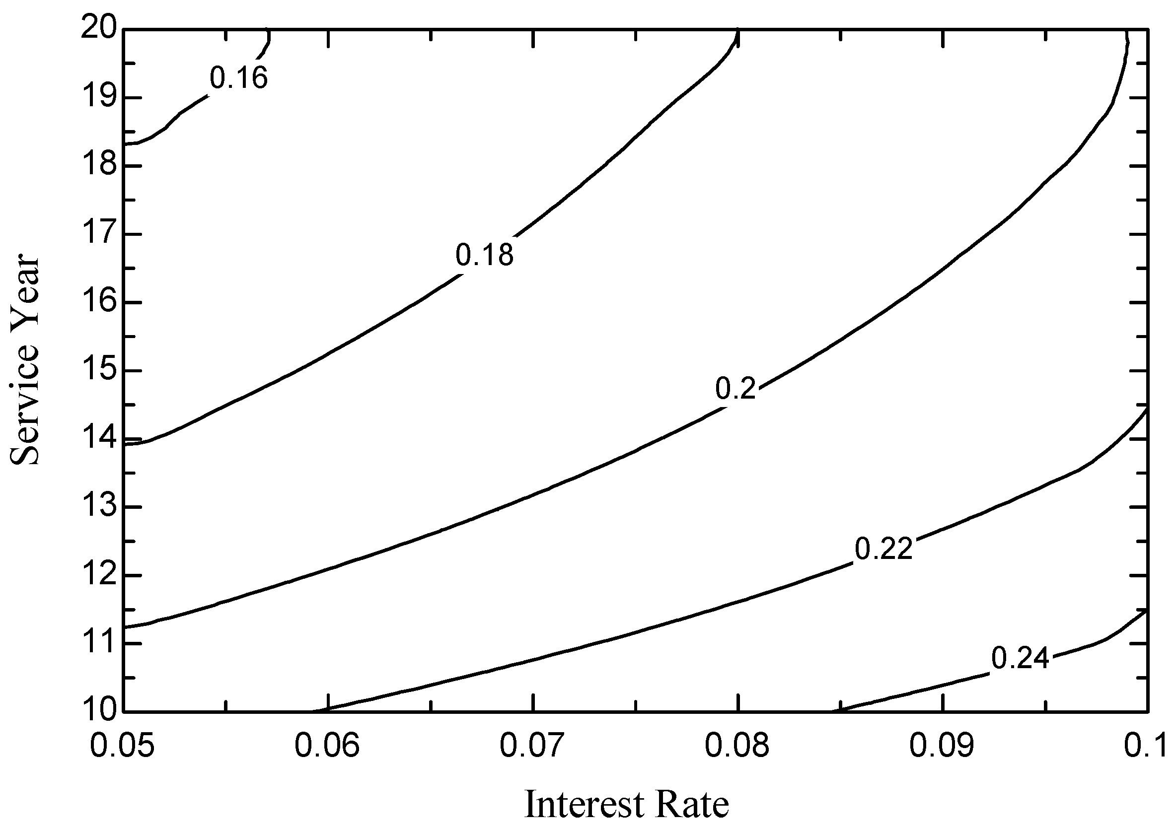
(3) System Service Life and Interest Rate
Figure 9 reveals the variations of unit exergy cost of electricity with interest rate and service life. From Equation (18), it can be seen that both the service life and interest rate influences the capital recovery coefficient, which has an impact on the levelized capital cost. When the interest rate is 6%, the service life increases from 10 years to 15 years, and the unit exergy cost of electricity decreases by 18.15%, while the unit exergy cost of electricity decreases by only 10.60% when the service life increases from 15 years to 20 years. The increasing service life of the hybrid CCHP system naturally declines the levelized capital cost and reduces the unit electricity cost. Their relationship occurs in a nonlinear influence, and the electricity cost declines quickly at the lower service life. When the service life is 20 years, the unit exergy cost of electricity increases by 16.87% with the increase of interest rate from 6% to 9%. It shows that the increase of interest rate will lead to the increase of the unit exergy cost of electricity.
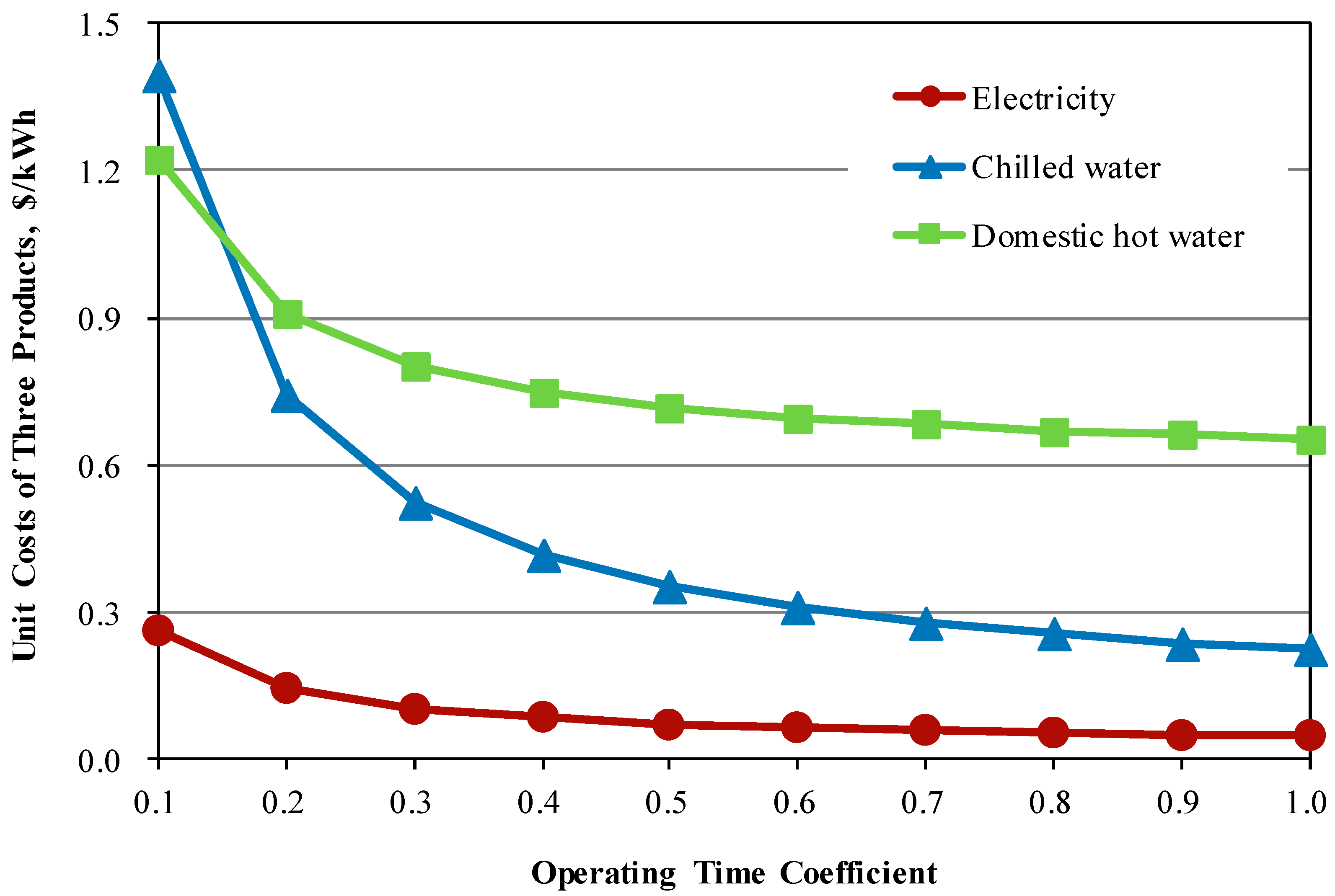
(4) Operating Time Coefficient
Figure 10 shows the variations of the unit exergy cost of products with the operating time coefficient. The ratio of the system annual operating hours to 8760 hours is defined as the operating time coefficient. The unit exergy cost of the corresponding products also declines with the increase of operation time coefficient. At the lower operating time coefficient, its increase vastly effects the unit cost of products. With the increase of operation time, the decline gradient will become less. As the operating time coefficient increases from 0.1 to 0.5, the unit exergy cost of electricity, chilled water and domestic hot water decreases by 72.3%, 74.7%, and 41.4%, respectively. The cost of other products is less sensitive to the operation time than chilled water due to the largest exergy cost at the lower operation time coefficient.
5. Conclusions
This paper designed a CCHP system based on solar thermal biomass gasification and proposed the exergy analysis and exergoeconomic analysis for revealing the irreversibility and cost allocating. The following conclusions were obtained.
The energy performance of the system is better in the cooling mode while the exergy analysis results show that the exergy efficiency of the system is higher in the heating mode than in the cooling mode. Because of the larger temperature difference between fluids, the lowest exergy efficiency occurs in the components of exhaust gas heat exchanger which provides domestic hot water. While the exergy loss of ICE is the largest, as it takes up approximately 49.2% of the overall exergy destruction and loss. The exergy destruction and loss of gasifier for biomass-steam gasification assisted by solar heat is about 17.5% of the overall exergy destruction. Improving performance and reducing exergy destruction of ICE and gasifier is helpful to effectively utilize distributed biomass and solar energies.
The costing principles for multi-streams from one control volume significantly affect the cost collations of products of the hybrid CCHP system. The principle of high energy level and high cost is well reflected in the modified exergoeconomic method based on energy level. Comparing the modified exergoeconomic method with the earlier method, the results show that the unit exergy cost of electricity with higher energy level increases by 0.038 $/kWh, while the unit exergy cost for the remaining products with lower energy level reduce. The particular CCHP system with the existing design parameters, when the cost of biomass is 0.051 $/kg, the unit exergy cost of electricity, chilled water, heating water, and domestic hot water are 0.164, 0.852, 0.666, and 0.961 $/kWh, respectively. The results of sensitivity analysis show that the initial investment cost of gasification system has a great influence on the unit exergy cost of products and the increase of annual operation time considering the solar energy results in the decline of products’ cost.
Author Contributions
Writing–original draft, J.W. (Jin Wu); Methodology and project administration, J.W. (Jiangjiang Wang); Simulations, J.W. (Jing Wu); Writing–review & editing, C.M.
Funding
This study was supported by the National Natural Science Foundation of China (Grant No. 51876064).
Acknowledgments
We gratefully acknowledge the anonymous reviewers for their insightful comments on the manuscript.
Conflicts of Interest
The authors declare no conflicts of interest.
Nomenclature
| surface area of the parabolic dish mirror (m2) | |
| A | ash |
| C | exergy cost ($/h) |
| c | unit exergy cost ($/kWh) |
| average specific heat (kJ/(kg·K)) | |
| DNI | solar radiation illuminance (W/m2) |
| Ex | exergy (kW) |
| specific exergy (kJ/kg) | |
| exergoeconomic factor | |
| FC | fixed carbon |
| H | enthalpy (kJ) |
| h | specific enthalpy (kJ/kg) |
| LHV | low heat value (MJ/Nm3) |
| m | mass flow (kg/s) |
| M | moisture |
| maximum power generation capacity (kW) | |
| n | service life (year) |
| p | product |
| Q | heat transfer (kW) |
| R | universal gas constant (kJ/((kmol·K)) |
| S | entropy (kJ/K) |
| s | specific entropy (kJ/(kg·K)) |
| i | interest rate |
| T | temperature (°C or K) |
| x | molar ratio |
| V | volatile |
| Z | investment cost ($) |
| Greek symbols | |
| reflectivity of the parabolic dish mirror | |
| operating hours (h) | |
| interception factor | |
| shading factor | |
| efficiency (%) | |
| exergy efficiency | |
| capital recovery coefficient | |
| fixed cost as a percentage of initial investment cost | |
| ratio of exergy to energy | |
| Subscripts and superscripts | |
| a | ambient |
| Abs | absorber |
| b | biomass |
| C | carbon |
| ch | chemical |
| cond | conduction |
| conv | convection |
| cw | cooling water |
| des | destruction |
| dw | domestic hot water |
| exh | exhaust gas |
| Eva | evaporator |
| f | fuel |
| H | hydrogen |
| HG | high pressure generator |
| HX | heat exchanger |
| in | inlet |
| jw | jacket water |
| k | species |
| l | loss |
| LG | low pressure generator |
| N | nitrogen |
| 0 | standard reference state |
| O | oxygen |
| out | outlet |
| p | product |
| ph | physical |
| rad | radiation |
| rw | chilled water |
| sol | solar |
| sw | space heating water |
| W | mechanical power |
| w | tap water |
References
- Liu, T.; Liu, Q.; Lei, J.; Sui, J. A new solar hybrid clean fuel-fired distributed energy system with solar thermochemical conversion. J. Clean. Prod. 2019, 213, 1011–1023. [Google Scholar] [CrossRef]
- No, S.-Y. Application of bio-oils from lignocellulosic biomass to transportation, heat and power generation—A review. Renew. Sustain. Energy Rev. 2014, 40, 1108–1125. [Google Scholar] [CrossRef]
- Wang, J.-J.; Yang, K.; Xu, Z.-L.; Fu, C. Energy and exergy analyses of an integrated CCHP system with biomass air gasification. Appl. Energy 2015, 142, 317–327. [Google Scholar] [CrossRef]
- Wang, J.; Sui, J.; Jin, H. An improved operation strategy of combined cooling heating and power system following electrical load. Energy 2015, 85, 654–666. [Google Scholar] [CrossRef]
- Wang, J.; Yang, Y. Energy, exergy and environmental analysis of a hybrid combined cooling heating and power system utilizing biomass and solar energy. Energy Convers. Manag. 2016, 124, 566–577. [Google Scholar] [CrossRef]
- Li, H.; Zhang, X.; Liu, L.; Zeng, R.; Zhang, G. Exergy and environmental assessments of a novel trigeneration system taking biomass and solar energy as co-feeds. Appl. Therm. Eng. 2016, 104, 697–706. [Google Scholar] [CrossRef]
- Zhang, X.; Li, H.; Liu, L.; Zeng, R.; Zhang, G. Analysis of a feasible trigeneration system taking solar energy and biomass as co-feeds. Energy Convers. Manag. 2016, 122, 74–84. [Google Scholar] [CrossRef]
- Kalinci, Y.; Hepbasli, A.; Dincer, I. Performance assessment of hydrogen production from a solar-assisted biomass gasification system. Int. J. Hydrog. Energy 2013, 38, 6120–6129. [Google Scholar] [CrossRef]
- Li, R.; Zeng, K.; Soria, J.; Mazza, G.; Gauthier, D.; Rodriguez, R.; Flamant, G. Product distribution from solar pyrolysis of agricultural and forestry biomass residues. Renew. Energy 2016, 89, 27–35. [Google Scholar] [CrossRef]
- Molino, A.; Larocca, V.; Chianese, S.; Musmarra, D. Biofuels Production by Biomass Gasification: A Review. Energies 2018, 11, 811. [Google Scholar] [CrossRef]
- Chang, K.-H.; Lou, K.-R.; Ko, C.-H. Potential of bioenergy production from biomass wastes of rice paddies and forest sectors in Taiwan. J. Clean. Prod. 2019, 206, 460–476. [Google Scholar] [CrossRef]
- Rahbari, A.; Venkataraman, M.B.; Pye, J. Energy and exergy analysis of concentrated solar supercritical water gasification of algal biomass. Appl. Energy 2018, 228, 1669–1682. [Google Scholar] [CrossRef]
- Xu, W.D.; Duan, J.; Mao, W.J. Process Study and Exergy Analysis of a Novel Air Separation Process Cooled by LNG Cold Energy. J. Therm. Sci. 2014, 23, 77–84. [Google Scholar] [CrossRef]
- Liu, J.C.; Zhang, X.J.; Xu, Y.J.; Chen, Z.Y.; Chen, H.S.; Tan, C.Q. Economic Analysis of using Above Ground Gas Storage Devices for Compressed Air Energy Storage System. J. Therm. Sci. 2014, 23, 535–543. [Google Scholar] [CrossRef]
- Han, C.H.; Kim, K.H. Entransy and Exergy Analyses for Optimizations of Heat-Work Conversion with Carnot Cycle. J. Therm. Sci. 2016, 25, 242–249. [Google Scholar] [CrossRef]
- Yang, K.; Zhu, N.; Ding, Y.; Chang, C.; Wang, D.; Yuan, T. Exergy and exergoeconomic analyses of a combined cooling, heating, and power (CCHP) system based on dual-fuel of biomass and natural gas. J. Clean. Prod. 2019, 206, 893–906. [Google Scholar] [CrossRef]
- Seyyedi, S.M.; Hashemi-Tilehnoee, M.; Rosen, M.A. Exergy and exergoeconomic analyses of a novel integration of a 1000 MW pressurized water reactor power plant and a gas turbine cycle through a superheater. Ann. Nucl. Energy 2018, 115, 161–172. [Google Scholar] [CrossRef]
- Kohl, T.; Teles, M.; Melin, K.; Laukkanen, T.; Järvinen, M.; Park, S.W.; Guidici, R. Exergoeconomic assessment of CHP-integrated biomass upgrading. Appl. Energy 2015, 156, 290–305. [Google Scholar] [CrossRef]
- Wang, J.; Li, M.; Ren, F.; Li, X.; Liu, B. Modified exergoeconomic analysis method based on energy level with reliability consideration: Cost allocations in a biomass trigeneration system. Renew. Energy 2018, 123, 104–116. [Google Scholar] [CrossRef]
- Wang, Z.; Han, W.; Zhang, N.; Su, B.; Liu, M.; Jin, H. Assessment of off-design performance of a combined cooling, heating and power system using exergoeconomic analysis. Energy Convers. Manag. 2018, 171, 188–195. [Google Scholar] [CrossRef]
- Wang, J.; Mao, T. Cost allocation and sensitivity analysis of multi-products from biomass gasification combined cooling heating and power system based on the exergoeconomic methodology. Energy Convers. Manag. 2015, 105, 230–239. [Google Scholar] [CrossRef]
- Soltani, S.; Mahmoudi, S.M.S.; Yari, M.; Morosuk, T.; Rosen, M.A.; Zare, V. A comparative exergoeconomic analysis of two biomass and co-firing combined power plants. Energy Convers. Manag. 2013, 76, 83–91. [Google Scholar] [CrossRef]
- Wang, J.; Mao, T.; Wu, J. Modified exergoeconomic modeling and analysis of combined cooling heating and power system integrated with biomass-steam gasification. Energy 2017, 139, 871–882. [Google Scholar] [CrossRef]
- Ma, Y.J.; Dang, X.G.; Shan, Z.H. Thermal Analysis and Identification of Potential Fire-proof Energy Building Material Based on Artificial Leather. J. Therm. Sci. 2019, 28, 88–96. [Google Scholar] [CrossRef]
- Lazzaretto, A.; Tsatsaronis, G. SPECO: A systematic and general methodology for calculating efficiencies and costs in thermal systems. Energy 2006, 31, 1257–1289. [Google Scholar] [CrossRef]
- Xu, L.; Yan, P.; Huang, H.Y.; Han, W.J. Effects of Hot Steam Injection from the Slot at the Trailing Edge on Turbine Nozzle Vane Flow Field. J. Therm. Sci. 2008, 17, 298–304. [Google Scholar] [CrossRef]
- Erlach, B.; Tsatsaronis, G.; Cziesla, F. A new approach for assigning costs and fuels to cogeneration products. Int. J. Thermodyn. 2001, 4, 145–156. [Google Scholar]
- Peng, Q.; Zhang, S.; Guo, J. Resonable structure of supplementary equation used for cost analysis in thermal economics. Therm. Power Gener. 2003, 1, 29–31. [Google Scholar]
- Wang, Z.; Han, W.; Zhang, N.; Liu, M.; Jin, H. Exergy cost allocation method based on energy level (ECAEL) for a CCHP system. Energy 2017, 134, 240–247. [Google Scholar] [CrossRef]
- Wang, J.; Ma, C.; Wu, J. Thermodynamic analysis of a combined cooling, heating and power system based on solar thermal biomass gasification. Appl. Energy 2019, 247, 102–115. [Google Scholar] [CrossRef]
- Klein, S.A. Software, Engineering Equation Solver (EES)(6.883-3D); F-Chart Software: Madison, WI, USA, 2012; Available online: http://www.fchart.com/ees/ (accessed on 30 April 2019).
- Yang, Y. Study of Solar-Hybrid Combined Cooling Heating and Power System Drvien by Natural Gas; North China Electric Power University: Baoding, China, 2017. [Google Scholar]
- Wang, J.; Mao, T.; Sui, J.; Jin, H. Modeling and performance analysis of CCHP (combined cooling, heating and power) system based on co-firing of natural gas and biomass gasification gas. Energy 2015, 93, 801–815. [Google Scholar] [CrossRef]
- Wang, J.; Xie, X.; Lu, Y.; Liu, B.; Li, X. Thermodynamic performance analysis and comparison of a combined cooling heating and power system integrated with two types of thermal energy storage. Appl. Energy 2018, 219, 114–122. [Google Scholar] [CrossRef]
- Bejan, A.; Tsatsaronis, G.; Moran, M. Thermal Design and Optimization; John Wiley & Sons, Inc.: New York, NY, USA, 1996. [Google Scholar]
- Chu, S.X.; Liu, L.H. Analysis of terrestrial solar radiation exergy. Sol. Energy 2009, 83, 1390–1404. [Google Scholar] [CrossRef]
- Ptasinski, K.J.; Prins, M.J.; Pierik, A. Exergetic evaluation of biomass gasification. Energy 2007, 32, 568–574. [Google Scholar] [CrossRef]
- Yue, T.; Lior, N. Exergo economic analysis of solar-assisted hybrid power generation systems integrated with thermochemical fuel conversion. Appl. Energy 2017, 191, 204–222. [Google Scholar] [CrossRef]
- Yue, T.; Lior, N. Exergo-economic competitiveness criteria for hybrid power cycles using multiple heat sources of different temperatures. Energy 2017, 135, 943–961. [Google Scholar] [CrossRef]
Figure 1.
Energy flowcharts of the novel combined cooling, heating, and power (CCHP) system based on solar thermal biomass gasification.
Figure 1.
Energy flowcharts of the novel combined cooling, heating, and power (CCHP) system based on solar thermal biomass gasification.

Figure 2.
Exergy efficiency () of components.

Figure 3.
Average exergy destruction and loss of components in the two operation modes.

Figure 4.
Unit cost of internal combustion engine under two economic methods.

Figure 5.
Unit exergy cost of products in the two operation modes.

Figure 6.
Exergoeconomic factors of components calculating in two methods.

Figure 7.
Variations of unit exergy cost of electricity with investment of the Solar heat collector (SHC) and the gasification system.
Figure 7.
Variations of unit exergy cost of electricity with investment of the Solar heat collector (SHC) and the gasification system.

Figure 8.
Variations of unit exergy cost of electricity with biomass cost.

Figure 9.
Variations of unit exergy cost of electricity with interest rate and service life.

Figure 10.
Variations of unit exergy cost of products with operating time coefficient in cooling mode.
Figure 10.
Variations of unit exergy cost of products with operating time coefficient in cooling mode.


Table 1.
Base design parameters.
| Components | Parameters | Value |
|---|---|---|
| Biomass steam subsystem | Heat collecting area (m2) | 115.6 |
| Radiation intensity(W/m2) | Winter 600/Summer 800 | |
| Steam temperature (°C) | 450 (state 2) | |
| Tap water temperature (°C) | 25 (state 18, 17, and 15) | |
| HX-01 inlet temperature (°C) | 800 (state 4) | |
| HX-01 outlet temperature (°C) | 43 (state 5) | |
| ICE | ICE inlet (°C) | 25 (state 7) |
| Exhaust gas heat (kW) | 47.16 | |
| Jacket water heat (kW) | 50.31 | |
| Exhaust gas thermal efficiency (%) | 15.94 | |
| power generation (kW) | 100 | |
| AC/H | Exhaust gas temperature (°C) | 478/170 (state 11/12) |
| Jacket water temperature (°C) | 85/70 (state 9/10) | |
| Chilled water temperature (°C) | 14/7 (state 20/19) | |
| Space heating water temperature (°C) | 50/60 (state 20/19) | |
| Cooling water temperature (°C) | 32/36 (state 21/22) | |
| HX-02 | Exhaust gas temperature (°C) | 120 (state 13) |
| Domestic hot water temperature (°C) | 60 (state 16) |
Table 2.
Energy principles of the CCHP system (The definitions of symbols are given in the Nomenclature section).
Table 2.
Energy principles of the CCHP system (The definitions of symbols are given in the Nomenclature section).
| Components | Energy Balance Equations | Auxiliary Equations |
|---|---|---|
| Solar dish collector | , , , Further detailed data for heat transfer can be found in Ref. [30]. | |
| Biomass gasification | Further detailed data for heat transfer can be found in Ref. [30]. | |
| ICE | , , Further detailed data for heat transfer can be found in Ref. [32,33,34] | |
| AC/H | (summer) (winter) Further detailed data for heat transfer can be found in Ref. [5] | |
| HX |
Table 3.
Component parameters of biomass.
| Item | Parameters | |||||
|---|---|---|---|---|---|---|
| Wheat straw | Proximate Analysis (wt. %) | V | FC | A | M | - |
| 70.11 | 17.47 | 9.14 | 3.28 | - | ||
| Elemental analysis (wt. %) | C | H | O | N | S | |
| 45.17 | 5.75 | 35.66 | 0.86 | 0.14 | ||
| LHV (MJ/Nm3) | 17.4 | |||||
Table 4.
System initial investment cost parameters and fuel price.
| Items | Component | Unit Cost | Capacity | Investment (103 $) |
|---|---|---|---|---|
| Investment | G | 362 ($/kW) | 309.2 (kW) | 111.93 |
| SHC | 340.28 ($/m2) | 115.6 (m2) | 39.39 | |
| ICE | 695.04 ($/kW) | 100 (kW) | 69.50 | |
| AC/H | 173.76 ($/kW) | 109.1 (kW) | 18.97 | |
| HX 01 | 30.408 ($/kW) | 54.3 (kW) | 1.59 | |
| HX 02 | 30.408 ($/kW) | 7.6 (kW) | 0.29 | |
| Cost parameter | Annual operating hours, h | 1500 | Service life, year | 20 |
| Maintenance cost coefficient | 2.5% | Interest rate | 6.15% | |
| Fuel price | Biomass ($/ton) | 50.68 | Tap water ($/ton) | 1.035 |
Table 5.
Cost of products of the hybrid CCHP system in two operation modes.
| Operation Mode | Project | Electricity | Chilled Water/Heating Water | Domestic Hot Water |
|---|---|---|---|---|
| Cooling mode | Energy cost ($/kWh) | 0.164 | 0.044 | 0.052 |
| Exergy cost ($/kWh) | 0.164 | 0.852 | 0.961 | |
| Heating mode | Energy cost ($/kWh) | 0.164 | 0.054 | 0.052 |
| Exergy cost ($/kWh) | 0.164 | 0.588 | 0.961 |
© 2019 by the authors. Licensee MDPI, Basel, Switzerland. This article is an open access article distributed under the terms and conditions of the Creative Commons Attribution (CC BY) license (http://creativecommons.org/licenses/by/4.0/).
Share and Cite
MDPI and ACS Style
Wu, J.; Wang, J.; Wu, J.; Ma, C. Exergy and Exergoeconomic Analysis of a Combined Cooling, Heating, and Power System Based on Solar Thermal Biomass Gasification. Energies 2019, 12, 2418. https://doi.org/10.3390/en12122418
AMA Style
Wu J, Wang J, Wu J, Ma C. Exergy and Exergoeconomic Analysis of a Combined Cooling, Heating, and Power System Based on Solar Thermal Biomass Gasification. Energies. 2019; 12(12):2418. https://doi.org/10.3390/en12122418
Chicago/Turabian StyleWu, Jin, Jiangjiang Wang, Jing Wu, and Chaofan Ma. 2019. "Exergy and Exergoeconomic Analysis of a Combined Cooling, Heating, and Power System Based on Solar Thermal Biomass Gasification" Energies 12, no. 12: 2418. https://doi.org/10.3390/en12122418
Note that from the first issue of 2016, this journal uses article numbers instead of page numbers. See further details here.