
An Improved Droop Control Method for Multi-Terminal VSC-HVDC Converter Stations

1
Power Electronics & Renewable Energy Research Center, Xi’an Jiaotong University, No. 28, Xianning West Road, Xi’an 710049, China
2
Department of Energy Technology, Aalborg University, Pontoppidanstraede 101, Aalborg DK-9220, Denmark
*
Author to whom correspondence should be addressed.
Energies 2017, 10(7), 843; https://doi.org/10.3390/en10070843
Submission received: 1 March 2017
/
Revised: 11 June 2017
/
Accepted: 19 June 2017
/
Published: 23 June 2017
(This article belongs to the Special Issue Electric Power Systems Research 2017)
Abstract
:Multi-terminal high voltage direct current transmission based on voltage source converter (VSC-HVDC) grids can connect non-synchronous alternating current (AC) grids to a hybrid alternating current and direct current (AC/DC) power system, which is one of the key technologies in the construction of smart grids. However, it is still a problem to control the converter to achieve the function of each AC system sharing the reserve capacity of the entire network. This paper proposes an improved control strategy based on the slope control of the DC voltage and AC frequency (V–f slope control), in which the virtual inertia is introduced. This method can ensure that each AC sub-system shares the primary frequency control function. Additionally, with the new control method, it is easy to apply the secondary frequency control method of traditional AC systems to AC/DC hybrid systems to achieve the steady control of the DC voltage and AC frequency of the whole system. Most importantly, the new control method is better than the traditional control method in terms of dynamic performance. In this paper, a new control method is proposed, and the simulation model has been established in Matlab/Simulink to verify the effectiveness of the proposed control method.
1. Introduction
In recent years, wind, solar, and other new energy technologies have developed rapidly. However, they have the characteristics of intermittence and randomness, which makes it more and more limiting for the traditional power grid to absorb ultra-large-scale renewable energies. The flexible multi-terminal DC grid technology is one of the effective techniques to solve this problem [1,2,3,4,5,6,7].
The traditional control strategy of converter stations focuses on the transmission power. The converter acts as a specified power supplier in the inverter side, or a load in the rectifier side. Thus, it plays a negative role in regulating the power of the entire grid [8,9,10,11]. As is well known, the purpose of traditional small-scale power grids interconnecting to larger grids is to enable each small grid to share the moment of inertia and frequency regulation function. Thus, they can support or act as a standby for each other to make the whole system more stable. If the converter stations are controlled as specified power suppliers or loads, it will greatly weaken the advantages of the interconnected system [12,13,14]. The proposed control strategy will solve this problem.
In order to ensure the steady operation of the multi-terminal high voltage direct current transmission based on voltage source converter (VSC-HVDC) grid, the basic control requirements are to maintain the stability of the DC voltage and to balance the DC power [15,16,17,18,19]. In order to keep the DC voltage stable and the system power balanced, both the voltage control and power control are commonly used [20,21]. At present, there are three main types of voltage control strategy: the voltage margin control, the voltage droop control, and the voltage droop control with a voltage margin [22]. These three control modes can realize the coordinated control of DC voltage and power, but they are lacking in a real-time interaction for the AC networks, and cannot provide a primary frequency control function for each sub-AC grid. Thus, scholars have put forward a method that combines the DC voltage power droop with the AC frequency power droop [1,23,24,25]. It can sustain DC voltage and provide the primary frequency control function to a sub-AC grid [16,17,18]. However, this control method is lacking in a dynamic flow balance method. During a load disturbance, this control method will lead to more transient power fluctuations [26].
This article proposes an improved droop control method. With every converter station using this control method in multi-terminal VSC-HVDC system, each AC system can share the primary frequency regulation service. All the generators can share their inertia in the hybrid AC/DC power system. The real-time interaction of each AC system is enhanced. Additionally, it is easy to apply the secondary frequency control method of traditional AC systems to the AC/DC hybrid system.
This paper proposes an improved control strategy based on the slope control of the DC voltage and AC frequency (V–f slope control), in which the virtual inertia is introduced. This paper is arranged as follows: In Section 2, the applied models of the whole hybrid AC/DC system are presented. Based on the model, in Section 3, the control strategy and the coordination method are proposed. In Section 4, the crucial parameters of the control strategy are discussed. In Section 5, the validity of the proposed control method is proved by simulation in Matlab/Simulink. Finally, the conclusion and the future work are presented in Section 6.
2. System and Model Description
2.1. DC Grid Description
The research object of this paper adopts a bipolar-operation, three-terminal HVDC system with a star topology. The bipolar-operation, three-terminal HVDC system of this paper is a hypothetical power system. The DC-side uses a unified rated voltage of ± 200 kV. DC lines adopt lumped parameters. The line capacitance effect is focused on the DC-side of the converter and the line inductance is ignored. The structure of the power grid is shown in Figure 1.
In Figure 1, areas A, B and C represent three asynchronous AC power grids. Point O is a node of the DC power grid. The multi-terminal DC power grid adopts overhead lines. These lines choose aluminum cable steel reinforced (ACSR)-720/50 with R = 0.04 (Ω/km), and adopt a four-splitting lead. The distances of OA, OB and OC are 100 km, 80 km and 40 km, respectively. The resistances of each line are:
2.2. AC Grid Description
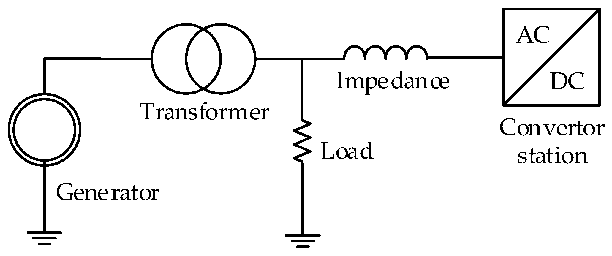
In Figure 1, the three AC systems A, B and C are asynchronous; each AC system is represented by an equivalent source and load. The synchronous generator model represents the power source, and the equivalent model of each AC system is shown in Figure 2.
The terminal voltage of the synchronous generator is 10 kV and it is connected to the 110 kV lines through a 10/110 kV transformer. The equivalent concentrated load and the line impedance are connected to the 110 kV line. The parameters of the AC grid are shown in Table 1 and Table 2.
In addition, 2% of the power loss is considered as output power, and it is distributed by the generators of the three areas according to per unit of their rate capacities.
2.3. Converter Station Description
In fact, typical VSC-HVDC converter stations always adopt modular multi-level topologies. The main research point of this paper is the method for the coordinated control of AC/DC power, so the control problem of the converter component level is ignored. To simplify the problem, it uses three-phase, two-level, triple-arm bridges with IGBT power semiconductors to replace the actual modular multi-level topology model.
3. Proposed Control Method
The new control method is based on the speed droop characteristics of traditional AC power grids and the voltage droop control of traditional HVDC converter stations; thus, it inherits the characteristics of the two traditional control methods.
For VSC-HVDC transmission systems, it is assumed that the converter station V2 is connected to the stable DC grid V1 through line impedance, as shown in Figure 3.
The transmission power from the DC grid to the converter can be expressed by Equation (2):
where P2 is the transmission power of the converter station, V1 is the voltage of the DC grid, and V2 is the DC-side voltage of the converter station.
In Equation (2), if ∆V is much less than V1, it can be ignored; then Equation (2) can be turned into Equation (3):
From Equation (3), it can be illustrated that the power transferred from the DC grid to the AC area is inversely proportional to the voltage of the DC terminal. If V2 < V1, the converter acts as an inverter; otherwise, it acts as a rectifier. The characteristics are shown in Figure 4.
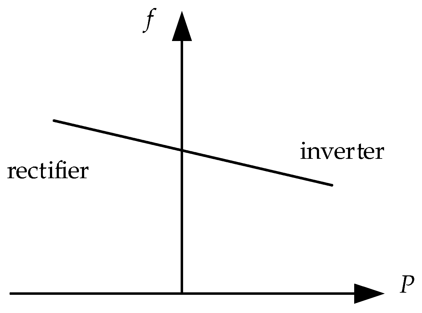
If the inverter acts as a power supplier in the AC side. It should be operated by the frequency and active power droop control to provide a primary frequency control function for the AC system. From the view of the rectifier side, it acts as a load of the AC-side. The control characteristic is that the frequency and active power are in a positive correlation. Therefore, the ideal control characteristic of the active power and frequency is shown in Figure 5.
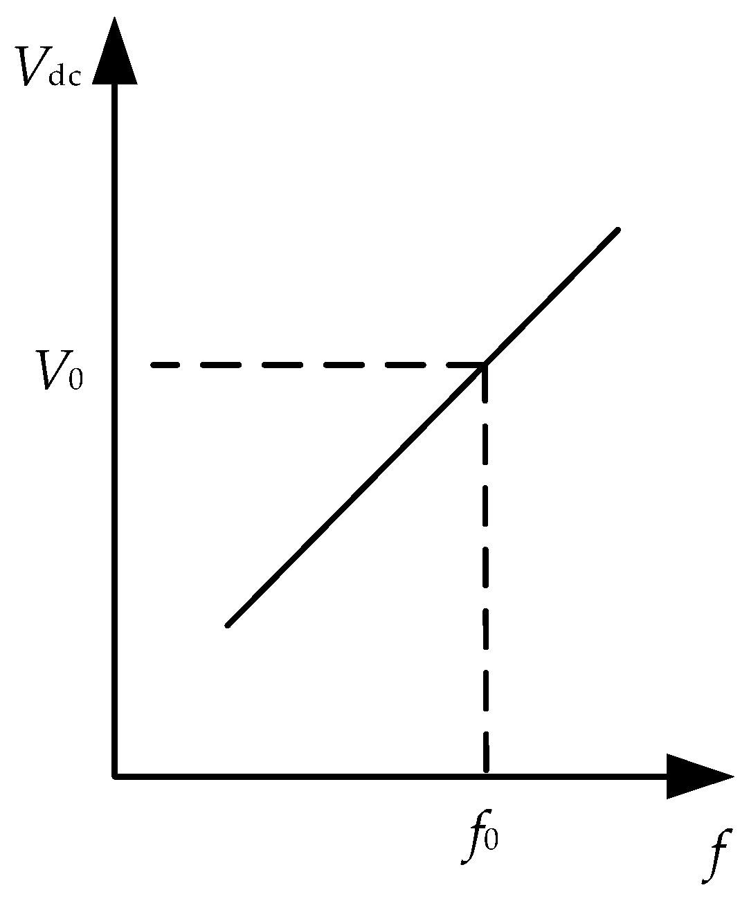
As shown in Figure 4 and Figure 5, if the converter station operates in the inverter state, when the frequency of the AC system decreases, the AC side hopes to obtain more active power to support its frequency; thus, it requires the terminal voltage of the DC-side to be decreased to satisfy a more active power transmission. When the frequency of the AC system increases, the AC-side hopes to obtain less active power and the terminal voltage of the DC-side should be increased. This requires the AC system frequency and DC voltage control to positively correlate, as Figure 6 shows.
If the converter station operates in the rectifier state, the control principle is the same as for the inverter state.
Based on the analysis above, this paper proposes a control method. It puts the converter DC voltage and AC frequency in a positive relationship, as shown in Figure 6. In addition, to make the converter automatically sense frequency fluctuations of the AC system and supply energy to AC grids, the converter should make the AC frequency as feedback in the outer control loop. The virtual inertia is introduced in the control strategy, which makes the converter achieve dynamic power sharing, as for the traditional synchronous generator when a load disturbance occurs in the AC system [26,27]. Additionally, to ensure that the converter has the ability to support DC voltage, the converter should also make DC voltage a feedback in the outer control loop. The control loop is shown in Figure 7.
In Figure 7, ω is the sampled AC frequency; ωref is the reference AC frequency, which equals 100π rad/s; Vdc_ref is the reference DC voltage of the converter station; and K1 is the slope coefficient of the AC frequency and DC voltage. When there is a need for AC systems to share the primary frequency regulation service, K1 can regulate the dynamic power that each AC system should undertake. The transfer functions, Equations (4) and (5), can be obtained from Figure 7:
where Kp and Ki are the coefficients of the proportional-integral (PI) controller, ∆T is the intermediate variable, and K2 and K3 are the virtual inertia coefficients. These should be designed carefully to provide virtual inertia to AC grids.
4. Parameter Designs
The parameters of the new control method for the VSC-HVDC converter station are K1, K2, K3, Kp and Ki. A suitable K1 can sustain the AC frequency and DC voltage both at the scheduled level when the load increases suddenly in one AC system (as for the simulation presented in Section 5.1). The reasonable design of parameters K2, K3, Kp and Ki can smooth the frequency fluctuation of the AC system. The design principle should be based on the premise of satisfying the dynamic power sharing, and then making full use of the inertia of all generators in the entire system.
4.1. The Design of Slope Coefficient K1
The DC voltage and AC frequency slope coefficient K1 is a key parameter in the new control method. It has a similar design principle to the typical speed-droop characteristics of traditional power plants. With respect to the typical speed-droop characteristics of traditional power plants, it requires a load fluctuation ∆P within the range of ± 5%; the whole range of primary frequency control is released when the frequency error is about ± 200 mHz. Therefore, the speed-droop coefficient K is the ratio of the maximum relative power fluctuation and the maximum frequency relative deviation [23]. The speed-droop coefficient is calculated by Equation (6):
where K is the speed-droop coefficient, Pn is the active power of the AC system, and fn is the rated frequency.
The method of designing the V–f control slope coefficient K1 is proposed—refer to the typical speed-droop coefficient design of K. K1 can be determined by the ratio of the maximum DC voltage relative deviation and the maximum frequency relative deviation. It can make the most of the permissible fluctuations of the DC voltage and AC frequency. It can be expressed by Equation (7). In this way, the slope coefficient of every converter station is equal. In fact, with respect to a multi-terminal VSC-HVDC system, the line impendence is very small, which results in a small deviation of the DC voltage among different converter stations.
It is assumed that the maximum DC voltage relative deviation is 10%. The frequency relative deviation is kept the same as for the traditional AC system (±200 mHz), and the base frequency is 50 Hz. The slope coefficient K1 can be calculated to be 25 from Equation (7).
4.2. The Design of Inertial Coefficients K2 and K3
A reasonable design for the inertial coefficients can make the VSC-HVDC converters provide a virtual inertia to AC grids that is similar to that of the traditional synchronous generators. The virtual inertia plays an important role in damping the high frequency fluctuation of power, and smoothing the frequency variation in transient processes. Several studies have investigated the virtual inertia of virtual synchronous generators (VSGs). These generally made the virtual inertia coefficient equal to the moment of inertia of the synchronous generator, realizing the power sharing in the dynamic processes [26,27]. Therefore, the time constant of the converter’s frequency loop should equal the inertia time constant of the generator to achieve similar characteristics to the synchronous generator. In Figure 7, the relationship between ∆ω and ∆T is expressed as Equation (5), while the swing equation of the generator can be expressed as Equation (8) [28]:
where ∆ω is the frequency deviation, ∆T is the deference of the turbine torque and the electromagnetic torque, D is damping torque coefficient, and J is the moment of inertia of the generator.
In fact, Equations (5) and (8) have a similar form. In Equation (5), the time constant of the frequency loop is K2·K3, making it equal to the inertia time constant of the generator. In this situation, the converters can provide virtual inertia to AC grids. A reasonable number for the inertia time constant is 5.2 [28]. Thus, Equation (9) can be obtained:
This paper assumes that K2 = 1; thus K3 = 5.2, according to Equation (9).
4.3. The Design of the Reference DC Voltage of Each Converter
When setting the reference DC voltage of the converter station, the transfer power should be considered. Assuming point O (Figure 1) is the center, the voltage at point O is kept at 400 kV. In the initial state, the power of the generator in area A is 488.7 MW, and the load is 380 MW. Thus, area A needs to transfer 108.7 MW to the DC grid. Because point O is 400 kV, and the resistance from point O to station A is 2 Ω, the reference DC voltage of station A can be found from Equation (10):
Using the same method, the voltages of station B and C can be found; they are 400.26 kV and 399.68 kV. The parameters of the converter station are shown in Table 3.
Additionally, with respect to the AC voltage amplitude control, this study uses reactive power and voltage droop control [28]. The method of designing the droop coefficient is similar to that for the speed-droop coefficient, which was described in Section 4.1. The reactive power and voltage droop coefficient can be described mathematically by Equation (11) [28]:
where KQ is the reactive power and voltage droop coefficient, Sn is the rating of the AC grid, and Vn is the rated AC voltage.
5. Simulation Study
To evaluate the proposed converter control strategy, an AC/DC hybrid parallel system model was built in Matlab/Simulink. For a special explanation, this control method was used for all converter stations in multi-terminal VSC-HVDCs. Two important functions were achieved by applying the new method. The first function was that it could realize asynchronous AC systems sharing their primary frequency control functions. The second function was that it was easy to apply the secondary frequency control method of traditional AC systems to the AC/DC hybrid system.
To evaluate the advantages of the proposed method, it was compared with the traditional V–f control method. The traditional V–f control method is proposed by reference [25].
5.1. Load Disturbances
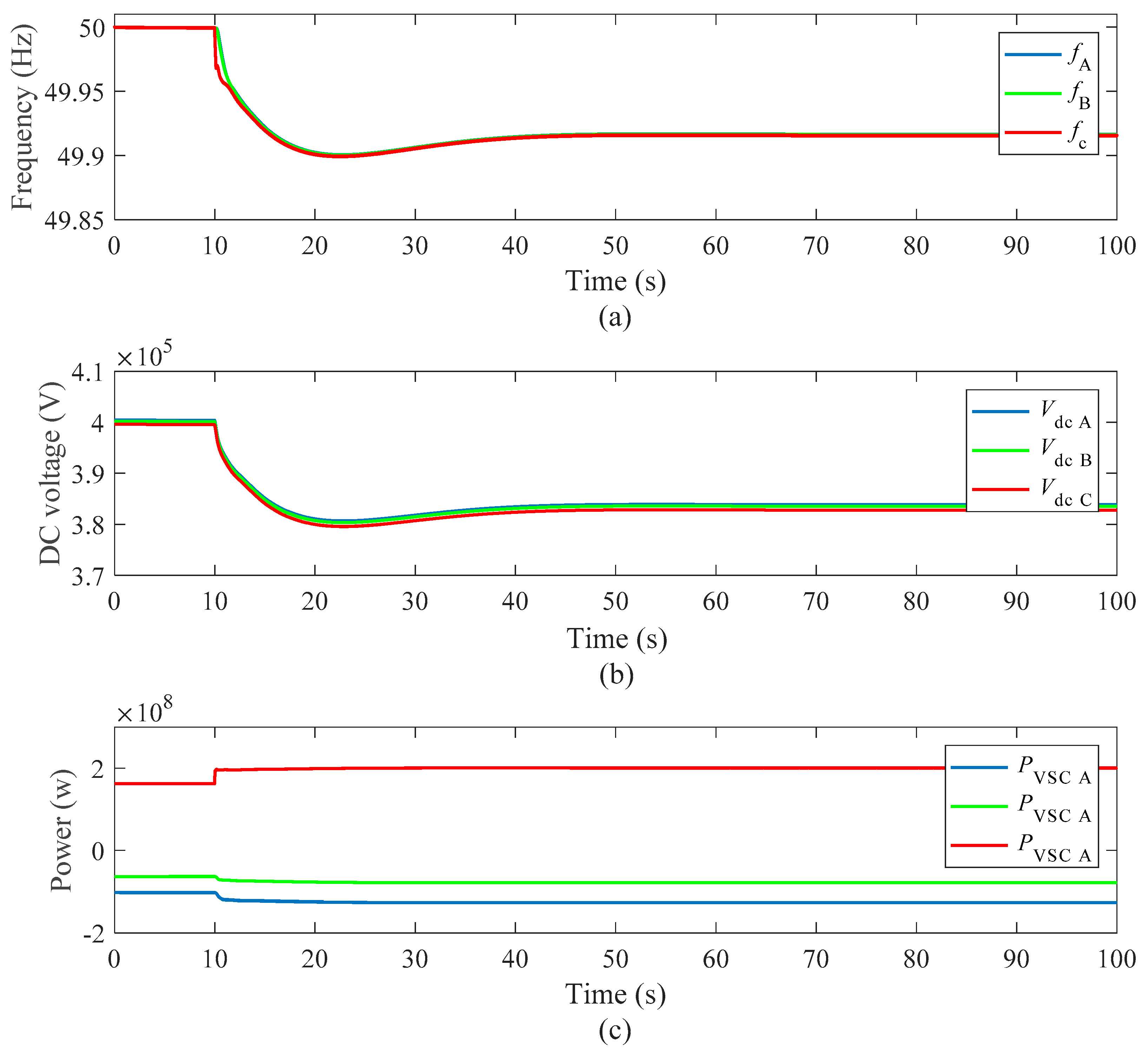
At 10 s, a load increase of 45 MW in area C was simulated. Before t = 10 s, area A and area B transmitted 100 MW and 60 MW of active power to area C through the DC grid, respectively. At t = 10 s, the load in area C increased 45 MW suddenly; the response waves of the frequency of each AC area, the DC-side voltage, and the transmission power of each converter are shown in Figure 8. The response of the traditional control method [25] is shown in Figure 9.
In Figure 8, from the frequency waveform, when the load disturbance occurred in area C at 10 s, the frequencies of areas A, B and C decreased. With the frequencies decreasing, the generators of the three areas increased their active power outputs due to the effect of the frequency droop control of the generators. From the power waveform, when a load step occurred in area C, areas A and B transferred more active power to area C automatically, to balance the power of the entire system. Thus, areas A and B shared their primary frequency control function with area C. Because the three converter stations used the same control method, we can suppose that if the load increase occurred in area A or B, it is reasonable to consider that the frequency of all the AC areas would have decreased, and all the generators would have output more power to balance the increased load. Therefore, it is reasonable to conclude that all sub-AC systems can share the primary frequency control function.
The waveform of Figure 9 is similar to that in Figure 8, while the dynamic performance of Figure 9 is poor, as after 10 s, the frequency and DC voltage waveforms of Figure 9 have more fluctuation than the frequency and DC voltage waveforms of Figure 8. During load disturbance, the traditional control method will lead to more transient power fluctuations. This conclusion can also be found in reference [26]. Thus, it proves that the new control method is better than the traditional control method in terms of dynamic performance.
5.2. Secondary Frequency Control
Based on the simulation condition in Section 5.1, when the system became stable after load steps in area C, the active power of the generator in area B increased 45 MW at t = 60 s. This was just an imitation of secondary frequency control (considering that the generator in area B was the frequency control generator). The response waves of the frequency, the DC-side voltage, and the transmission power of each converter are shown in Figure 10. The response of the traditional control method is shown in Figure 11.
In Figure 9, both the AC frequency and DC voltage decreased after the load step occurred in area C at t = 10 s. The frequency waveforms of areas A, B and C were very similar. Thus, we could make an approximation, considering that the three frequencies were the same, to use their average value as the frequency of the hybrid AC/DC power system. In order to restore the AC frequency and DC voltage to the scheduled value, the secondary frequency control strategy could be introduced into the hybrid AC/DC power system. The average frequency was used to compute the output of the frequency control generator (e.g., the generator of area B). By increasing the active power output of the frequency control generator, the AC frequency and the DC voltage could be restored to the scheduled value. Therefore, when t = 60 s, the active power output of the generator in area B increased 45 WM (computed by using the decreased value of the average frequency).
As the frequency and DC voltage waveforms show in Figure 10, after the generator in area B increased 45 MW of active power at t = 60 s, the AC frequencies and DC voltages were restored to around the scheduled value. From the power waveform, the transmission power of station A was restored to the initial value. This means that the output of the generator in area A was restored to the initial value, while from the power waveform, the transmission power of station B increased (the waveform goes down, because it is a negative value). This means that the load step of area C was totally borne by the generator of area B. Thus, this demonstrates that, with the new converter control strategy, the AC/DC hybrid system could use the traditional secondary frequency control (the average frequency is considered as the frequency of the hybrid system). From this phenomenon, it is reasonable to suppose that when there is a power shortage in any AC area of the hybrid system, all the terminal DC voltages and all the AC area frequencies will decrease. In this situation, in order to restore the AC frequencies and DC voltages to the scheduled value, the secondary frequency control strategy of traditional AC systems can be used. Because all the frequencies of different AC areas are very similar, and active power can be transferred automatically to meet the need (without a specified value), by increasing the suitable amount of active power output of the frequency control generator, the AC frequencies could be restored to the scheduled value. Thus, it is reasonable to conclude that, with the new control strategy of the converter station, it is easy to apply the secondary frequency control method of traditional AC systems to the AC/DC hybrid system.
With the same simulation condition, the response of the traditional control method is shown in Figure 11. The waveforms of Figure 11 are similar to those of Figure 10, while the dynamic performance of Figure 11 is poor, as at t = 10 s and t = 60 s, the waveforms of Figure 11 have more fluctuation than for Figure 10. Thus, this proves that the new control method is better than the traditional control method in terms of dynamic performance.
6. Conclusions and Future Work
For the power balance control of multi-terminal VSC-HVDC systems, this paper improves the traditional converter station control mode by adopting the DC voltage and AC frequency slope (positive correlation) control mode. The paper adds a virtual moment of inertia into the control strategy. The control method has two functions. First, it supports different asynchronous AC systems sharing their primary frequency control function. Second, it is convenient for the AC/DC hybrid system to inherit the secondary frequency control methods of the traditional AC system. The simulation results prove that the new control method is better than the traditional control method in terms of dynamic performance.
The new control method of the VSC-HVDC converter station has some potential value for further study. The frequency control strategy, grid-on and isolated island operation strategy and stability analysis will be researched in a follow-up study.
Acknowledgments
This research work is supported by National Key Research and Development Plan of China (2016YFB0900902), Science and Technology Project of Shandong Electric Power Company of SGCC (SGSDDK00KJJS1600143), and the Danish ForskEL project Harmonized Integration of Gas, District Heating and Electric Systems (HIGHE, 2014-1-12220).
Author Contributions
Hao Wang and Yue Wang put forward to the main idea and designed the entire structure of this paper. Weihao Hu guided the simulation and paper writing. Guozhao Duan and Wenti Wang performed the simulation and analyzed the results critically. Zhe Chen made good suggestions in the article modification process and revised the paper.
Conflicts of Interest
The authors declare no conflicts of interest.
References
- Adeuyi, O.D.; Cheah-Mane, M.; Liang, J.; Jenkins, N.; Wu, Y.; Li, C.; Wu, X. Frequency support from modular multilevel converter based multi-terminal HVDC schemes. In Proceedings of the 2015 IEEE Power & Energy Society General Meeting, Denver, CO, USA, 23 July–2 August 2015; pp. 1–5. [Google Scholar]
- Andreasson, M.; Wiget, R.; Dimarogonas, D.V.; Johansson, K.H.; Andersson, G. Distributed primary frequency control through multi-terminal HVDC transmission systems. In Proceedings of the 2015 American Control Conference (ACC), Chicago, IL, USA, 1–3 July 2015; pp. 5029–5034. [Google Scholar]
- Aouini, R.; Marinescu, B.; Kilani, K.B.; Elleuch, M. Improvement of transient stability in an AC/DC system with synchronverter based HVDC. In Proceedings of the 2015 12th International Multi-Conference on Systems, Signals & Devices (SSD), Sfax, Tunisia, 16–19 March 2015; pp. 1–6. [Google Scholar]
- Babazadeh, D.; Freizadeh, F.; Nordström, L. Distributed ancillary service support for independent AC-areas through HVDC grid. In Proceedings of the 2015 IEEE PowerTech Eindhoven, Eindhoven, Netherlands, 29 June–2 July 2015; pp. 1–6. [Google Scholar]
- Chaudhuri, N.R.; Chaudhuri, B. Adaptive Droop Control for Effective Power Sharing in Multi-Terminal DC (MTDC) Grids. IEEE Trans. Power Syst. 2013, 28, 21–29. [Google Scholar] [CrossRef]
- Xu, L.; Yao, L.; Sasse, C. Power electronics options for large wind farm integration: VSC-based HVDC transmission. In Proceedings of the 2006 IEEE PES Power Systems Conference and Exposition, Atlanta, GA, USA, 29 October–1 November 2006; pp. 760–767. [Google Scholar]
- Iov, F.; Sorensen, P.; Hansen, A.D.; Blaabjerg, F. Grid connection of active stall wind farms using a VSC based DC transmission system. In Proceedings of the 2005 European Conference on Power Electronics and Applications, Dresden, Germany, 11–14 September 2005; pp. 1–10. [Google Scholar]
- Zhong, Q.C.; Weiss, G. Synchronverters: Inverters That Mimic Synchronous Generators. IEEE Trans. Ind. Electron. 2011, 58, 1259–1267. [Google Scholar] [CrossRef]
- Li, Y.; Li, Y.W. Power management of inverter interfaced autonomous microgrid based on virtual frequency-voltage frame. IEEE Trans. Smart Grid 2011, 2, 30–40. [Google Scholar] [CrossRef]
- Li, Z.P.; Song, W.X.; Zhong, Q.C. Virtual synchronous generator and its applications in micro-grid. Proc. CSEE 2014, 34, 2951–2963. (In Chinese) [Google Scholar]
- Zhang, R.K.; Li, X.Y.; Yang, D.L. A frequency stability control strategy for interconnected VSC-MTDC transmission system. Power Syst. Technol. 2010, 34, 1–6. (In Chinese) [Google Scholar]
- Wiget, R.; Andersson, G. Optimal power flow for combined AC and multi-terminal HVDC grids based on VSC converters. In Proceedings of the 2012 IEEE Power and Energy Society General Meeting, San Diego, CA, USA, 22–26 July 2012; pp. 1–8. [Google Scholar]
- Mobarez, M.; Kashani, M.G.; Chavan, G.; Bhattacharya, S. A novel control approach for protection of multi-terminal VSC based HVDC transmission system against DC faults. In Proceedings of the 2015 IEEE Energy Conversion Congress and Exposition (ECCE), Montreal, QC, Canada, 20–24 September 2015; pp. 4208–4213. [Google Scholar]
- Chen, H.R.; Zhang, F.; Chang, Y. Improvement of power quality by VSC based multi-terminal HVDC. In Proceedings of the 2006 IEEE Power Engineering Society General Meeting, Montreal, QC, Canada, 18–22 June 2006; pp. 1–6. [Google Scholar]
- Chen, Y.; Dai, J.; Damm, G.; Lamnabhi-Lagarrigue, F. Nonlinear control design for a multi-terminal VSC-HVDC system. In Proceedings of the 2013 European Control Conference (ECC), Zurich, Switzerland, 17–19 July 2013; pp. 3536–3541. [Google Scholar]
- Gonzalez-Longatt, F.M.; Roldan, J.M.; Rueda, J.L. Impact of DC control strategies on dynamic behaviour of multi-terminal voltage-source converter-based HVDC after sudden disconnection of a converter station. In Proceedings of the 2013 IEEE Grenoble PowerTech (POWERTECH), Grenoble, France, 16–20 June 2013; pp. 1–6. [Google Scholar]
- Rouzbehi, K.; Zhu, J.; Zhang, W.; Gharehpetian, G.B.; Luna, A.; Rodriguez, P. Generalized voltage droop control with inertia mimicry capability-step towards automation of multi-terminal HVDC grids. In Proceedings of the 2015 International Conference on Renewable Energy Research and Applications (ICRERA), Palermo, Italy, 22–25 November 2015; pp. 1556–1561. [Google Scholar]
- Fu, J.; Yuan, Z.; Wang, Y.; Xu, S.; Wei, W.; Luo, Y. Control strategy of system coordination in Nanao multi-terminal VSC-HVDC project for wind integration. In Proceedings of the 2014 IEEE PES General Meeting | Conference & Exposition, National Harbor, MD, USA, 27–31 July 2014; pp. 1–5. [Google Scholar]
- Rao, H. Architecture of Nan'ao multi-terminal VSC-HVDC system and its multi-functional control. CSEE J. Power Energy Syst. 2015, 1, 9–18. [Google Scholar] [CrossRef]
- Raza, A.; Dianguo, X.; Yuchao, L.; Xunwen, S.; Williams, B.W.; Cecati, C. Coordinated operation and control of VSC based multiterminal high voltage DC transmission systems. IEEE Trans. Sustain. Energy 2016, 7, 364–373. [Google Scholar] [CrossRef]
- Chen, H.R.; Xu, Z. A novel DC voltage control strategy for VSC based multi-terminal HVDC system. Autom. Electr. Power Syst. 2006, 30, 28–33. (In Chinese) [Google Scholar]
- Yao, L.Z.; Wu, J.; Wang, Z.B.; Li, Y.; Lu, Z.X. Pattern analysis of future HVDC grid development. Proc. CSEE 2014, 34, 6007–6020. (In Chinese) [Google Scholar]
- Chaudhuri, N.R.; Majumder, R.; Chaudhuri, B. System frequency support through multi-terminal DC (MTDC) grids. IEEE Trans. Power Syst. 2013, 28, 347–356. [Google Scholar] [CrossRef]
- Chen, Y.; Dai, J.; Damm, G.; Lamnabhi-Lagarrigue, F. A detailed study on a DC-voltage-based control scheme using a multi-terminal HVDC system for frequency control. In Proceedings of the 2013 European Control Conference (ECC), Zurich, Switzerland, 17–19 July 2013; pp. 3530–3535. [Google Scholar]
- Haileselassie, T.M.; Uhlen, K. Primary frequency control of remote grids connected by multi-terminal HVDC. In Proceedings of the 2010 IEEE Power and Energy Society General Meeting, Minneapolis, MN, USA, 25–29 July 2010; pp. 1–6. [Google Scholar]
- Paquette, A.D.; Reno, M.J.; Harley, R.G.; Divan, D.M. Sharing transient loads: Causes of unequal transient load sharing in islanded microgrid operation. IEEE Ind. Appl. Mag. 2014, 20, 23–34. [Google Scholar] [CrossRef]
- Paquette, A.D.; Reno, M.J.; Harley, R.G.; Divan, D.M. Transient load sharing between inverters and synchronous generators in islanded microgrids. In Proceedings of the 2012 IEEE Energy Conversion Congress and Exposition (ECCE), Raleigh, NC, USA, 15–20 September 2012; pp. 2735–2742. [Google Scholar]
- Machowski, J.; Bialek, J.; Bumby, J. Power System Dynamics Stability and Control, 2nd ed.; John Wiley & Sons, Ltd.: West Sussex, UK, 2008. [Google Scholar]
Figure 1.
Structure of the multi-terminal DC grid.

Figure 2.
Control strategy diagram.

Figure 3.
Equivalent connection of the DC grid and converter station.

Figure 4.
Operation characteristics of the transmission power and the DC-side voltage.

Figure 5.
Control characteristics of the converter station.

Figure 6.
The positive relationship between the DC voltage and AC frequency.

Figure 7.
The control loop of the DC voltage and AC frequency.

Figure 8.
The waveforms of disturbances occurring in area C: (a) AC frequency of each sub-AC system; (b) DC-side voltage of each converter station; and (c) transmission power of each converter station.
Figure 8.
The waveforms of disturbances occurring in area C: (a) AC frequency of each sub-AC system; (b) DC-side voltage of each converter station; and (c) transmission power of each converter station.

Figure 9.
The waveforms of disturbances occurring in area C: (a) AC frequency of each sub-AC system, (b) DC-side voltage of each converter station, and (c) transmission power of each converter station.
Figure 9.
The waveforms of disturbances occurring in area C: (a) AC frequency of each sub-AC system, (b) DC-side voltage of each converter station, and (c) transmission power of each converter station.

Figure 10.
The waveforms of secondary frequency control: (a) AC frequency of each sub-AC system; (b) DC-side voltage of each converter station, and (c) transmission power of each converter station.
Figure 10.
The waveforms of secondary frequency control: (a) AC frequency of each sub-AC system; (b) DC-side voltage of each converter station, and (c) transmission power of each converter station.

Figure 11.
The waveforms of secondary frequency control: (a) AC frequency of each sub-AC system; (b) DC-side voltage of each converter station; and (c) transmission power of each converter station.
Figure 11.
The waveforms of secondary frequency control: (a) AC frequency of each sub-AC system; (b) DC-side voltage of each converter station; and (c) transmission power of each converter station.


Table 1.
Parameters of AC generators.
| Parameters/AC Area | A | B | C |
|---|---|---|---|
| Rated power (MW) | 600 | 400 | 100 |
| Initial power (MW) | 488.70 | 246.16 | 81.45 |
| Droop coefficient (Hz/MW) | 0.0042 | 0.0168 | 0.025 |
| Inertia constant (S) | 6.5 | 6.5 | 6.5 |
Table 2.
Parameters of AC line and load.
| Parameters/AC Area | A | B | C |
|---|---|---|---|
| Initial load (MW) | 380 | 180 | 240 |
| Line impedance (Ω) | 4 + j12.5 | 4 + j12.5 | 4 + j12.5 |
| Rated power of transformer (MVA) | 600 | 400 | 100 |
Table 3.
Parameters of the converter station.
| Parameters/AC Area | A | B | C |
|---|---|---|---|
| K1 | 25 | 25 | 25 |
| K2 | 1 | 1 | 1 |
| K3 | 5.2 | 5.2 | 5.2 |
| Kp | 1 | 1 | 1 |
| Ki | 100 | 100 | 100 |
| Vdc_ref (kV) | 400.54 | 400.26 | 399.68 |
© 2017 by the authors. Licensee MDPI, Basel, Switzerland. This article is an open access article distributed under the terms and conditions of the Creative Commons Attribution (CC BY) license (http://creativecommons.org/licenses/by/4.0/).
Share and Cite
MDPI and ACS Style
Wang, H.; Wang, Y.; Duan, G.; Hu, W.; Wang, W.; Chen, Z. An Improved Droop Control Method for Multi-Terminal VSC-HVDC Converter Stations. Energies 2017, 10, 843. https://doi.org/10.3390/en10070843
AMA Style
Wang H, Wang Y, Duan G, Hu W, Wang W, Chen Z. An Improved Droop Control Method for Multi-Terminal VSC-HVDC Converter Stations. Energies. 2017; 10(7):843. https://doi.org/10.3390/en10070843
Chicago/Turabian StyleWang, Hao, Yue Wang, Guozhao Duan, Weihao Hu, Wenti Wang, and Zhe Chen. 2017. "An Improved Droop Control Method for Multi-Terminal VSC-HVDC Converter Stations" Energies 10, no. 7: 843. https://doi.org/10.3390/en10070843
Note that from the first issue of 2016, this journal uses article numbers instead of page numbers. See further details here.