Structural Performance of a New Blind-Bolted Frame Modular Beam-Column Connection under Lateral Loading


1
Department of Architectural Engineering, Ajou University, Suwon 16499, Korea
2
Department of Architectural Engineering, Kyungpook National University, Daegu 41566, Korea
3
Department of Architectural Engineering, Kyung Hee University, Yongin 17104, Korea
*
Author to whom correspondence should be addressed.
Appl. Sci. 2019, 9(9), 1929; https://doi.org/10.3390/app9091929
Submission received: 19 March 2019
/
Revised: 27 April 2019
/
Accepted: 6 May 2019
/
Published: 10 May 2019
(This article belongs to the Special Issue Selected Papers from IMETI 2018)
Abstract
:This study proposes an effective steel frame modular system and evaluates the structural performance of its beam-column connection through experimental and analytical work. The new steel frame modular system utilizes the blind bolts, which allow free access to the structural members of the closed cross-section. In addition, the new modular system is designed such that the strength of its beam members is considerably lower than that of its column members to implement the strong column-weak beam concept. In order to investigate the effectiveness of the proposed modular beam-column connection, two types of specimens were designed and tested. One of the two specimens has four knee brace members to increase the bending stiffness of the connection, while the other does not have these components. The applied load versus displacement curves are plotted for the two specimens, and their failure modes are identified. Finally, a simplified analytical model for the modular beam-column connection is proposed, and its effectiveness is validated by performing its push-over analysis and comparing its results with the test results.
1. Introduction
Modular construction is an industrialized construction system, of which process mainly consists of the factory production of pre-engineered building units, the delivery of the fabricated units to the construction site and their fast assembly [1,2,3,4]. In recent years, modular construction has expanded its applications, due to its advantages, such as mass-fabrication, excellent quality, speed-up of the construction period. For example, there have been high-story modular buildings of more than 20 stories constructed in the US and Great Britain [2,5,6], and a 30 story hotel building has been completed using modularized prefabricated frame members in China [7,8,9,10].
It is highly important to develop effective connection details between unit modules, which allow the rapid assemblage of modular units without having any interference between their furnishing materials. In general, pre-fabricated unit modules include all of the final finishing materials, and thus it is not easy to achieve the simplicity of connection methods and to guarantee the structural safety of the completed modular building. Most commonly, unit modules are connected using high-tension bolts through access holes located at the bottom and top of the steel box columns [7,11]. Alternatively, it is also possible to pre-install nuts inside the column member and to connect unit modules by applying steel plates and bolts outside the member. Although the connection of unit modules by welding [12] is conceivable, it may cause fire during this process, and therefore is not frequently used on construction site.
Another critical issue with the development of effective modular construction is to create a modular structural system that is based on the so-called strong column-weak beam concept [11]. The strong column-weak beam behavior of the modular structural system is desirable since it can retain sufficient ductility under extreme loading conditions, such as earthquake, tsunami, flood and hurricane. In general, the modular building unit has both ceiling and floor beams, and most of the vertical loads are supported by the floor beams. Although the ceiling beams are barely functional as main structural members except when transporting and assembling modular units, the combination of these two components may result in the weak column-strong beam behavior, which is not desirable in the viewpoint of earthquake resistant design. In order to handle this issue, the concept of the special truss moment frame discussed in [13,14,15,16] may be applied to the design of the modular structural system. Its main idea is to install a Vierendeel opening between steel truss moment frames and use it as an effective energy dissipation device, thus the strong column-weak beam behavior can be guaranteed. However, this concept requires complicated connection details, which are difficult to be implemented in the assemblage process of modular units, thus a simpler solution than this needs to be developed.
The development of a reasonable finite element analysis model of module-to-module connections is also an important issue for the structural design of modular buildings. Generally, the joint between the column and beam is assumed to be rigid, while the horizontal and vertical connections between the modules to be an internal hinge [17]. For the detailed analysis of modular structures, a more refined model is required, but no well-validated research has been performed regarding this issue.
Considering all of the issues discussed above, this study proposes an effective steel frame modular system and evaluates the structural performance of its beam-column connection through experimental and analytical work. The new steel frame modular system utilizes the blind bolts, which allow free access to the structural members of the closed cross-section. Although the blind bolts have been used in the connection of steel frames [18,19,20,21], they have been very rarely used in the modular construction. In this study, the modular connections with blind bolts are suggested and their structural performance is investigated. In addition, the new modular system is designed the strength of its beam members is considerably lower than that of its column members to implement the strong column-weak beam concept. The results of the experimental work show that the proposed modular system can retain a sufficient level of ductility under extreme loading conditions. Finally, a simplified analytical model for the modular beam-column connection is proposed, and its effectiveness is validated by performing its push-over analysis and comparing its results with the test results.
The outline of this paper is as follows. In Section 2, the composition of the new modular building unit is described. The main features of the two types of blind bolts are explained, and the modular beam-column connection using these blind bolts is proposed. Section 3 provides the details of the experimental program to investigate the structural performance of the proposed connection, including the test specimens, testing equipment and test procedure. In Section 4, the general behavior of the test specimens is described and their failure mechanisms are analyzed in detail to demonstrate the effectiveness of the proposed modular system. The simple analytical model for the modular connection is suggested and validated against the test results in Section 5. Finally, the summary and concluding remarks are provided in Section 6.
2. Structural System
2.1. Modular Unit Composition
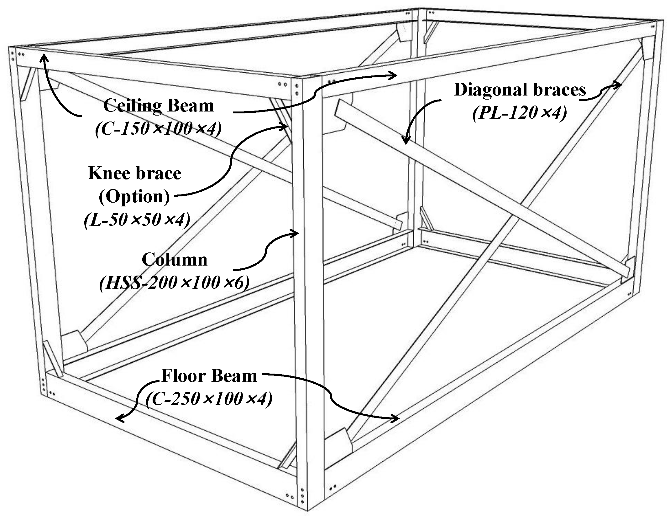
Figure 1 illustrates the steel frame unit module proposed in this study, which mainly consists of four columns, four ceiling beams, four floor beams and two double diagonal bracing members. Hollow structural steel (HSS) sections are used for the column members, and cold formed C sections for both of the ceiling and floor beam members. In order to resist lateral loads, the diagonal bracing members are added to the unit module in the long span direction, while it is reinforced by knee braces at the beam-column joints in the short span direction. In addition to the core structural members shown in the figure, the unit modules assembled on the construction site include wall furnishings, as well as a concrete floor.
2.2. Blind-Bolted Connection between Modular Units
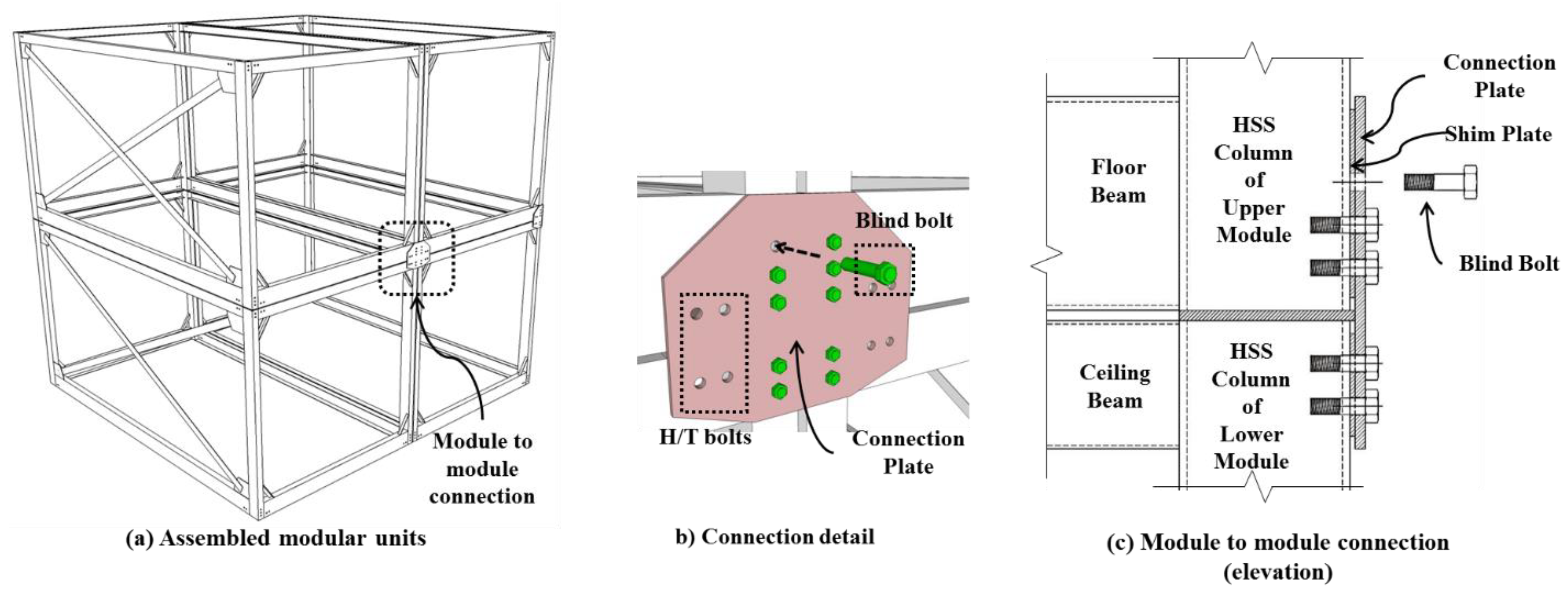
The details of the module-to-module connection proposed in this study are illustrated in Figure 2. In order to create an effective connection between the four modules, shown in the figure, a steel connection plate is added and connected by a number of blind and high-tension (H/T) bolts. The blind bolts are utilized in the portion of the connection plate attached to the HSS column members, which allows only limited access inside of the section. In contrast, the normal H/T bolts can be used in the portion attached to the C-shaped steel floor beam members. Totally, ten blind bolts and eight H/T bolts are required for this connection, as shown in Figure 2b.
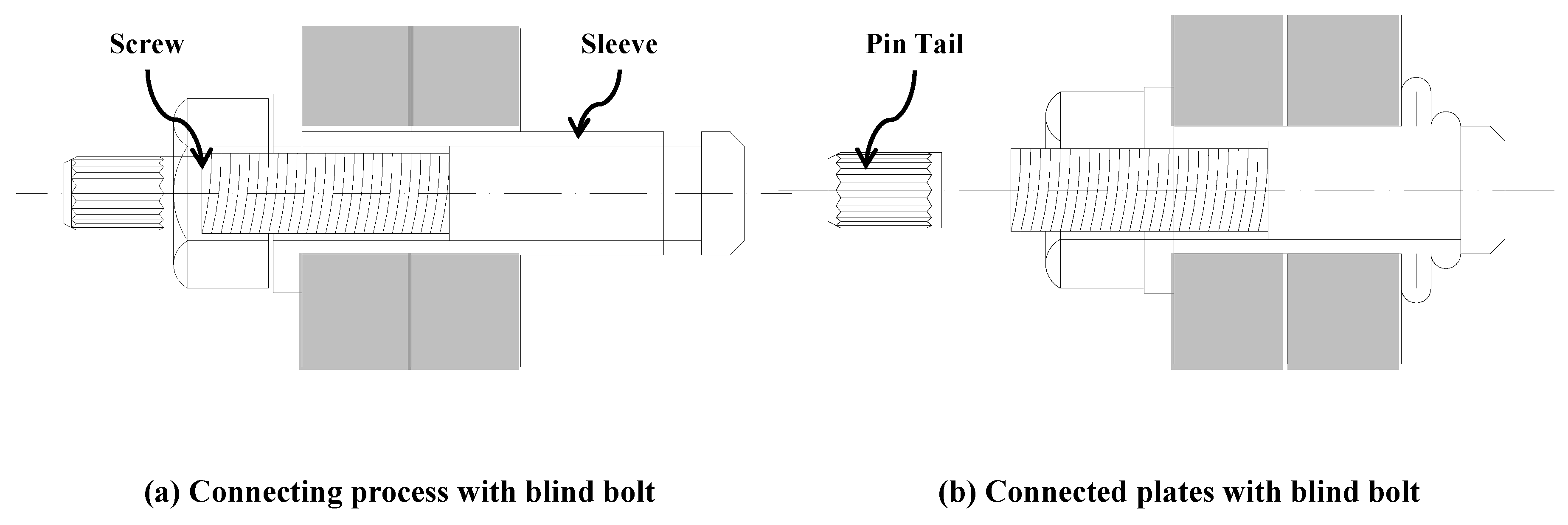
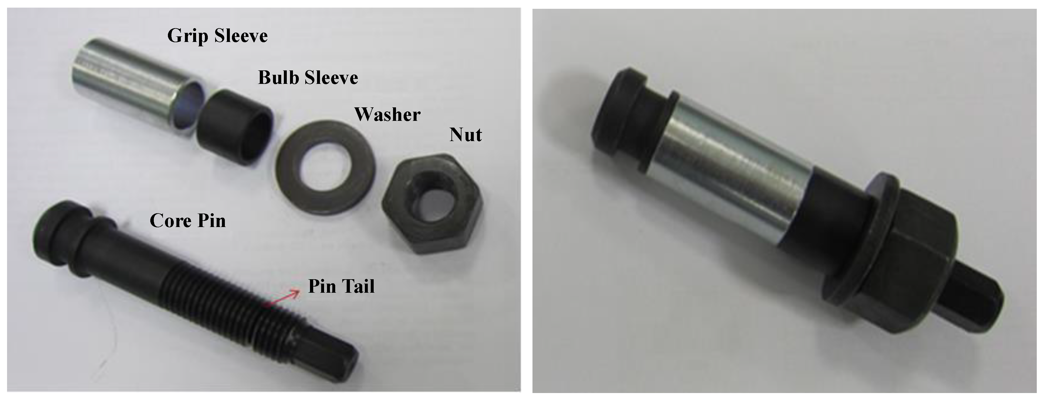
Figure 3 illustrates the details and fastening process of the blind bolts utilized in this study. The overall shape of the blind bolt and its main components are shown in Figure 4. The fastening process of the blind bolts is illustrated in Figure 3a,b. If a sufficient level of axial force is applied by a fastening tool after inserting the blind bolt into the hole, plastic deformation occurs in the sleeve, and the highly deformed portion of the sleeve forms a nut that can fix the main body to the connection plate. Then if the axial force reaches a limit value determined by the target torque, the pin-tail of the bolt is detached from its main body and its secure fastening can be guaranteed.
3. Experimental Program
3.1. Test Specimens
This section discusses the test specimens and their settings considered in this study to evaluate the structural performance of the beam-column connection of the proposed steel modular system subjected to lateral loading. The main difficulty of the test is that double beam and column members exist at the beam-column connection of the assembled modular units, and thus it is difficult to impose proper support conditions on the test specimens.
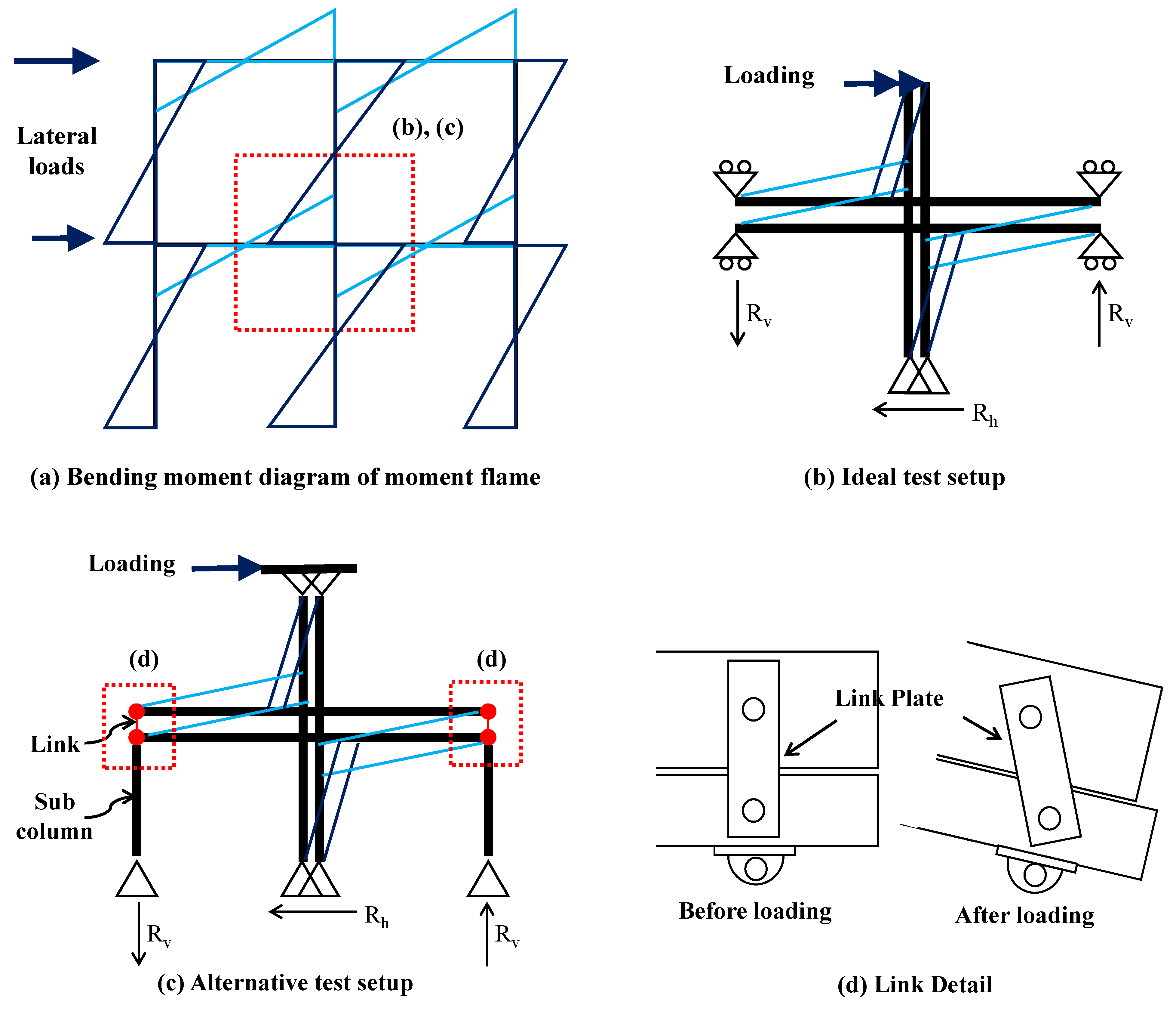
Figure 5a illustrates the typical bending moment diagram of a two-story modular frame system with two spans, which is subjected to two concentrated horizontal forces. Since it is not easy to perform a full-scale test on the entire frame structure, it would be better to cut some portion of the structure around the inner beam-column connection and perform a test on it. According to this scheme, an ideal test setup, which is obtained by cutting the frame structure along the dashed line indicated in Figure 5a, can be suggested, as shown in Figure 5b. In the ideal test setup, roller supports exist at the end of the horizontal floor and ceiling beams, and it is quite difficult to create specimen details exactly describing the given roller support conditions.
Instead, as an alternative, we propose the specimen setup, shown in Figure 5c, where a sub-column member is added to the end of the ceiling beam and the two horizontal beam members are loosely connected by a vertical link plate. The details of the vertical link plate are illustrated in Figure 5d. Under this setting, there may be an additional contribution to the horizontal displacement at the top of the double main columns induced by the rigid body rotation of the entire specimen. This additional displacement must be subtracted from the horizontal displacement measured at the top of the double main columns. This issue will be discussed in more details in Section 4.1.
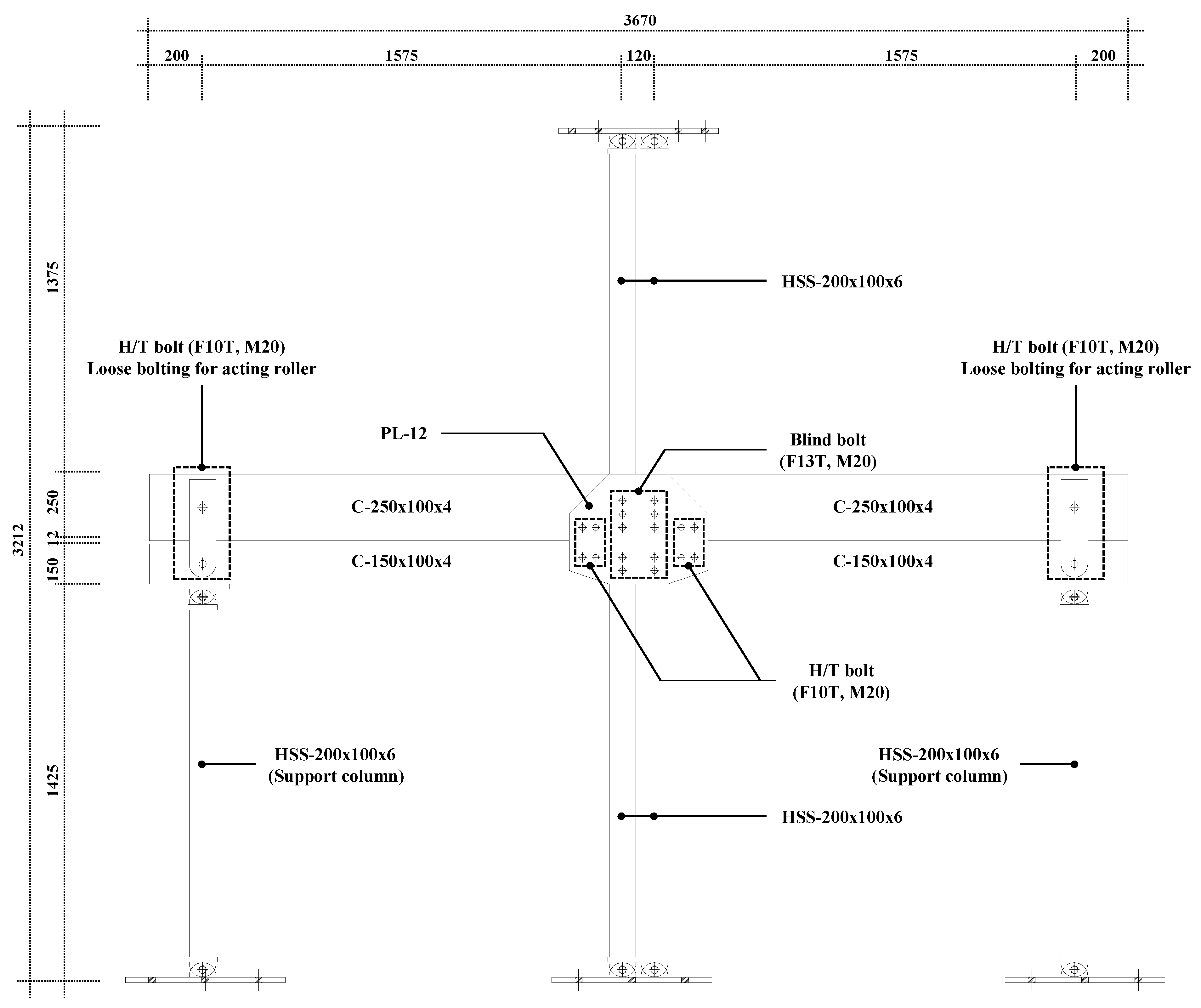
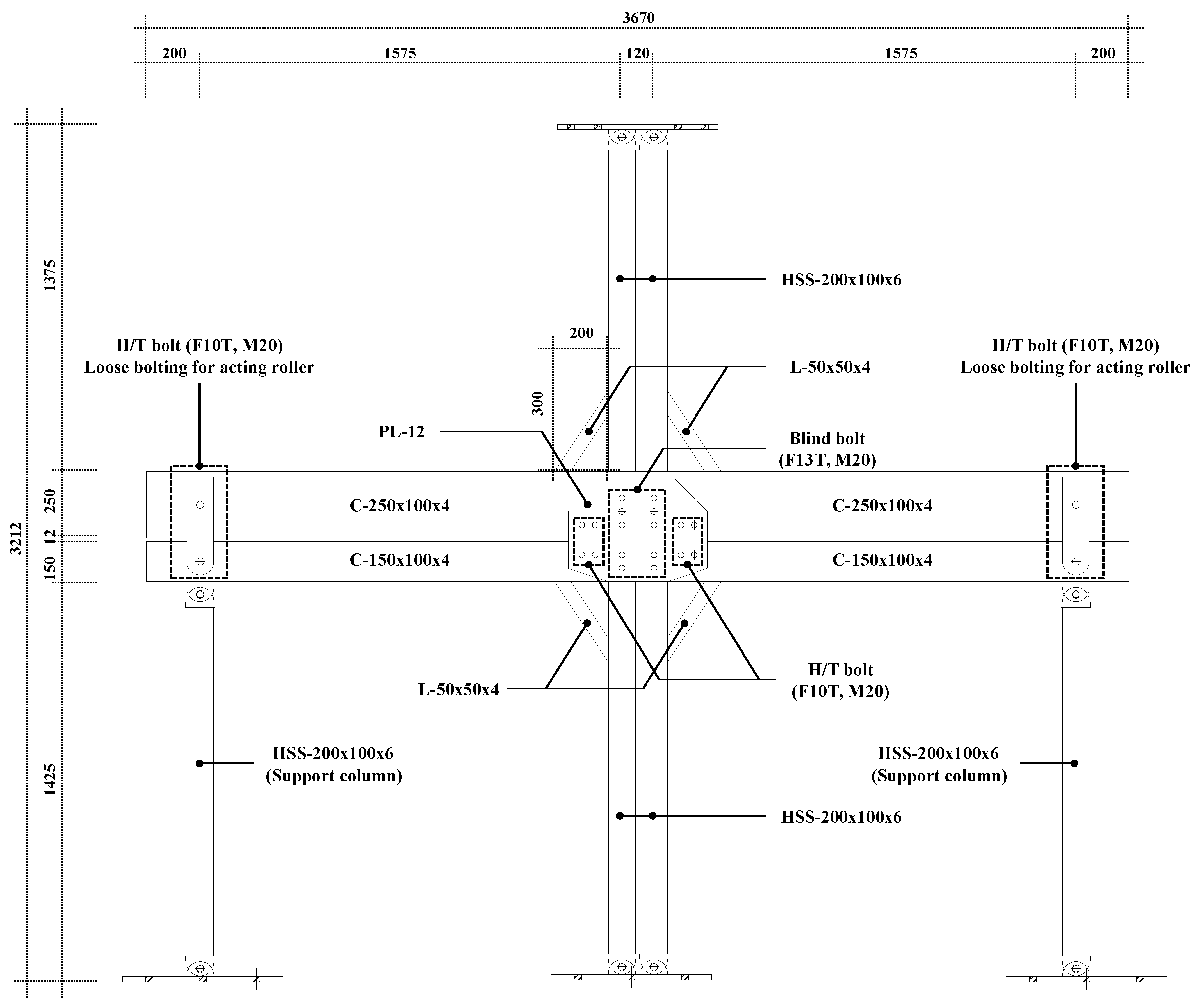
In order to investigate the effectiveness of the beam-column connection of the proposed steel frame modular unit, two types of specimens (specimens IC_OB_F and IC_OB_B) were manufactured and tested. Specimen IC_OB_B has four knee bracing members with a cross section of L50×50×6 to increase the bending stiffness of the beam-column connection. In contrast, specimen IC_OB_F does not have these components. Except the use of the knee bracings, the two specimens are identical as indicated in Table 1, which lists all the frame members and connection components used in the two specimens. The detailed drawings of specimens IC_OB_F and IC_OB_B are provided in Figure 6 and Figure 7, respectively. Two types of steel materials (SS400 and SM490) were used for the test specimens as indicated in Table 2. Their yield and ultimate strengths were measured per ASTM A370 [22], and are also summarized in the table. Table 3 shows the material properties of blind bolts.
3.2. Testing Equipment and Procedure
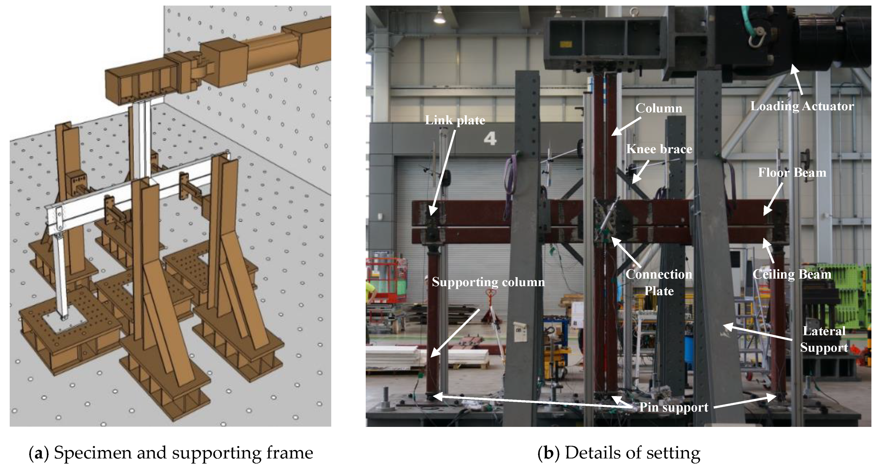
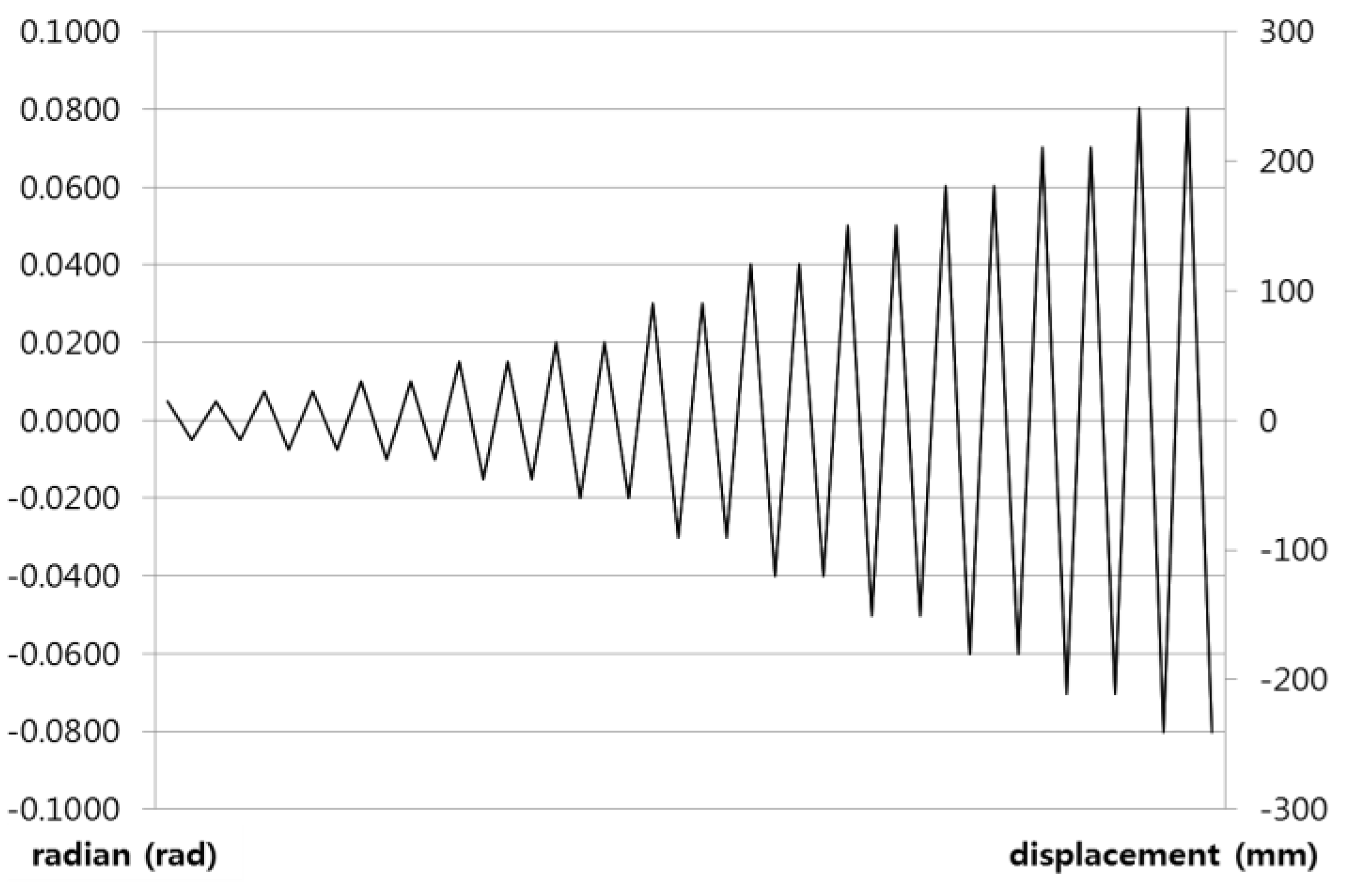
Figure 8 illustrates the actual test specimen setup and its details based on the scheme discussed in Section 3.1. Two steel frames with sufficiently high stiffness were attached to the top and bottom of the specimen in order to evenly transmit the lateral force generated by a hydraulic actuator to the two columns and to fix the specimen firmly on the ground, respectively. Cyclic loading was applied to the specimen using the hydraulic actuator with a maximum capacity of 500 kN, which allows the displacement-based loading control. As shown in Figure 9, the cyclic loading sequence consists of 11 steps, each of which includes identical two cycles, and the rotational angle gradually increased from 0.005 rad at the first step to 0.08 rad at the last step. The magnitude of loading was measured by the load cell included in the actuator.
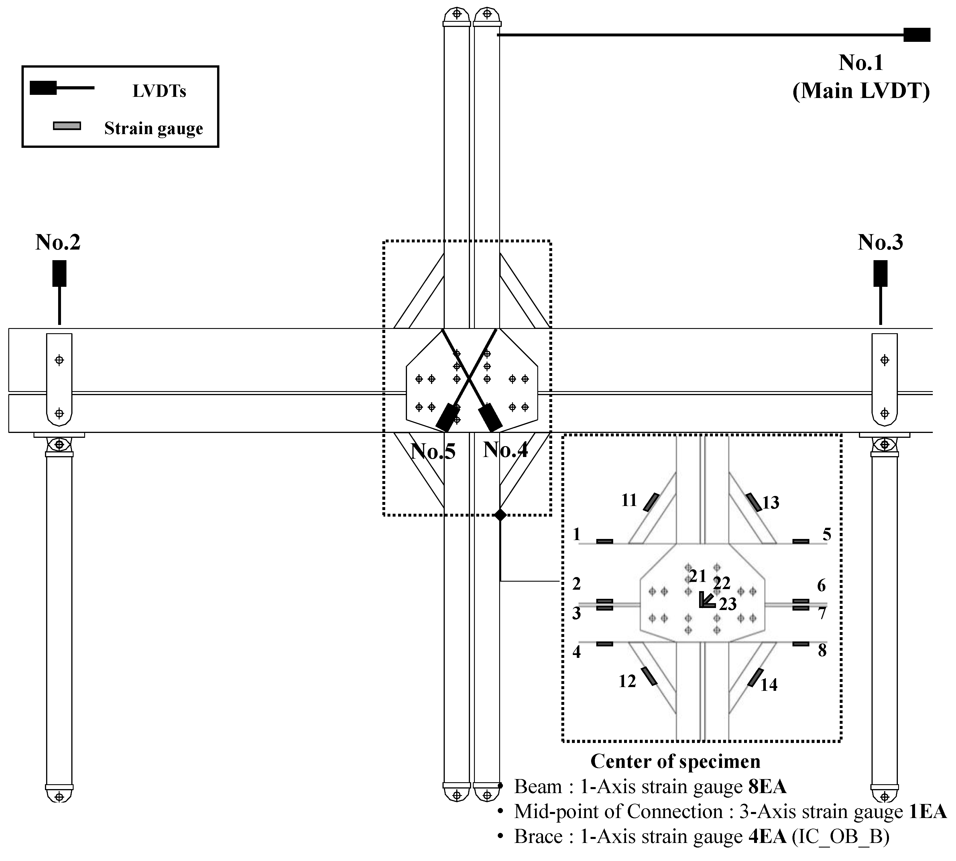
Figure 10 illustrates the setup of linear variable differential transducers (LVDTs) and strain gauges. Among the five LVDTs installed, three LVDTs from No. 1 to No. 3 monitored the lateral displacement of the test specimen and vertical displacements at the roller supports and link connections. The other two LVDTs (Nos. 4 and 5) were used to measure the shear deformation of the steel connection plate, shown in Figure 2b. As indicated in the figure, eleven and fifteen strain gauges were attached to the modular frame for IC_OB_F and IC_OB_B specimens, respectively. Their main role is to judge if yielding occurs at various locations of the test specimen.
4. Lateral Resistance of Modular Beam-Column Connections
4.1. General Behavior and Failure Modes
Table 4 summarizes the test results, such as the yielding member, drift ratio, displacement value, load value, initial stiffness at the occurrence of first yielding, as well as the drift ratio, displacement value, load value at peak load during the hysteresis cycles. As mentioned in Section 3.1, the horizontal displacement measured by LVDT 1 includes the contribution from the rigid body rotation of the entire specimen. In order to remove this unnecessary contribution, the rigid body rotation was calculated from the vertical displacements measured at LVDTs 2 and 3, and the additional horizontal displacement induced by it at the top of the double main columns (location of LVDT 1) was calculated. Then, the horizontal displacement measured at LVDT 1 was subtracted by the calculated additional horizontal displacement. All of the displacements and drift ratios listed in Table 4 are the values recalculated through this procedure.
In case of Specimen IC_OB_F without any knee bracings, first yielding occurred in the ceiling beam for both positive and negative loadings, its initial stiffness at the first yielding is approximately 500 kN/m, and the peak load is about 50 kN. Following the first yielding of the ceiling beam, its local buckling also happened with excessive deformation, and finally the specimen failed by the fracture at the welded connection between the ceiling beam and column.
In contrast, Specimen IC_OB_B with knee bracings showed a different failure mechanism. Its first yielding occurred in both the ceiling and floor beams almost at the same time. Upon the first yielding, its initial stiffness is approximately 1,100 kN/m, which is almost twice as high as that of the IC_OB_F specimen. Its peak load is about 82 kN, which is 60% higher than that of the IC_OB_F specimen. After the yielding of the ceiling beam, its local buckling also occurred, and its stiffness was gradually degraded, due to plastic deformation. The specimen eventually failed by the buckling of the knee bracings and floor beams.
4.2. Hysteresis Curves and Discussion
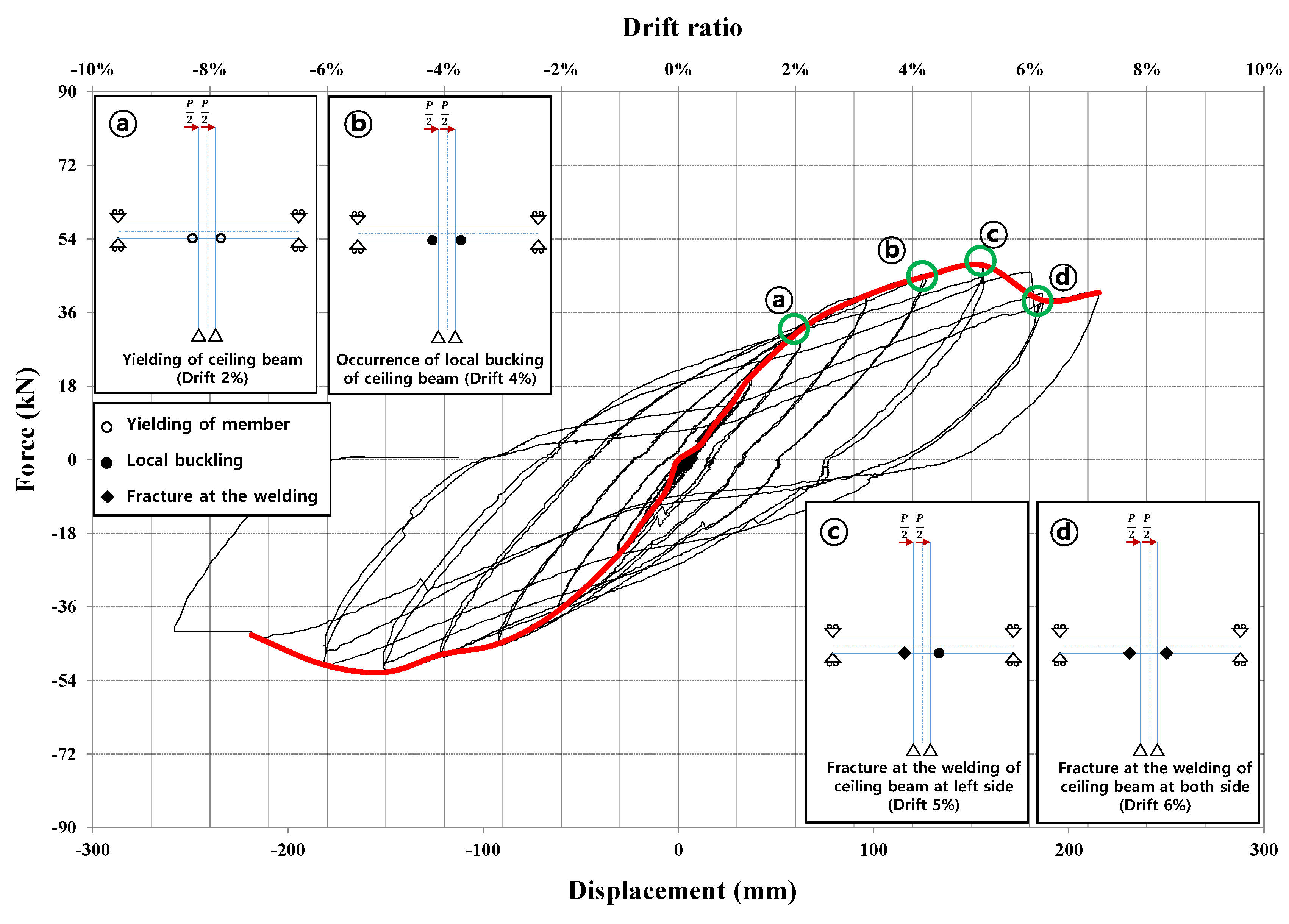
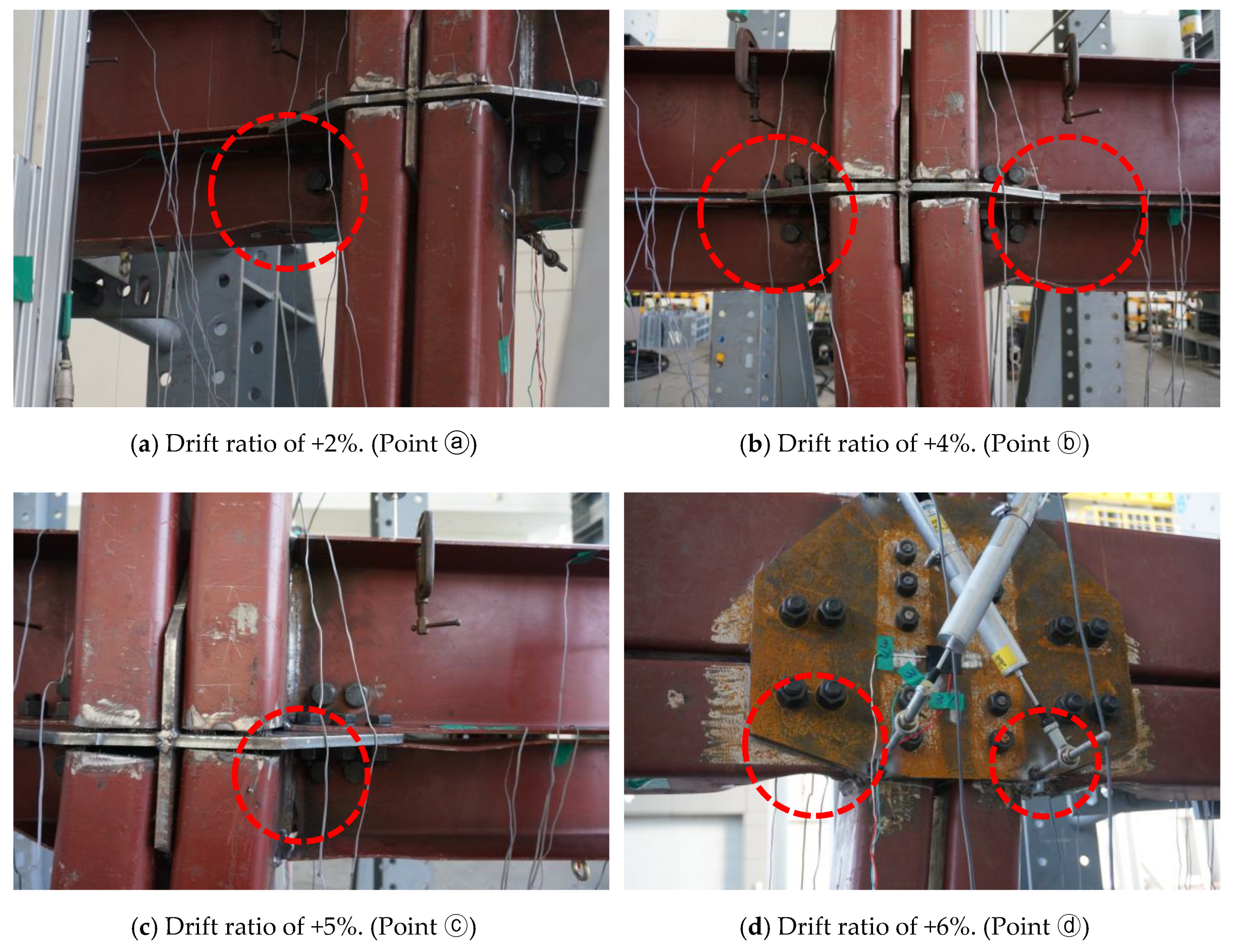
Figure 11 presents the hysteresis curve of Specimen IC_OB_F and its backbone curve. It also indicates the failure sequence of main structural components of the specimen and the drift ratios at which each failure occurred. The details of the failed structural components are given in Figure 12. At the drift ratio of 2%, the ceiling beam yielded (Figure 12a), and the local buckling at its flange and web were observed at the drift ratios of 4%, respectively (Figure 12b). The welded connection between the ceiling beam and column on the left side was fractured at the drift ratio of 5% (Figure 12c), which was followed by the same type of failure at the welded connection on the right side (Figure 12d).
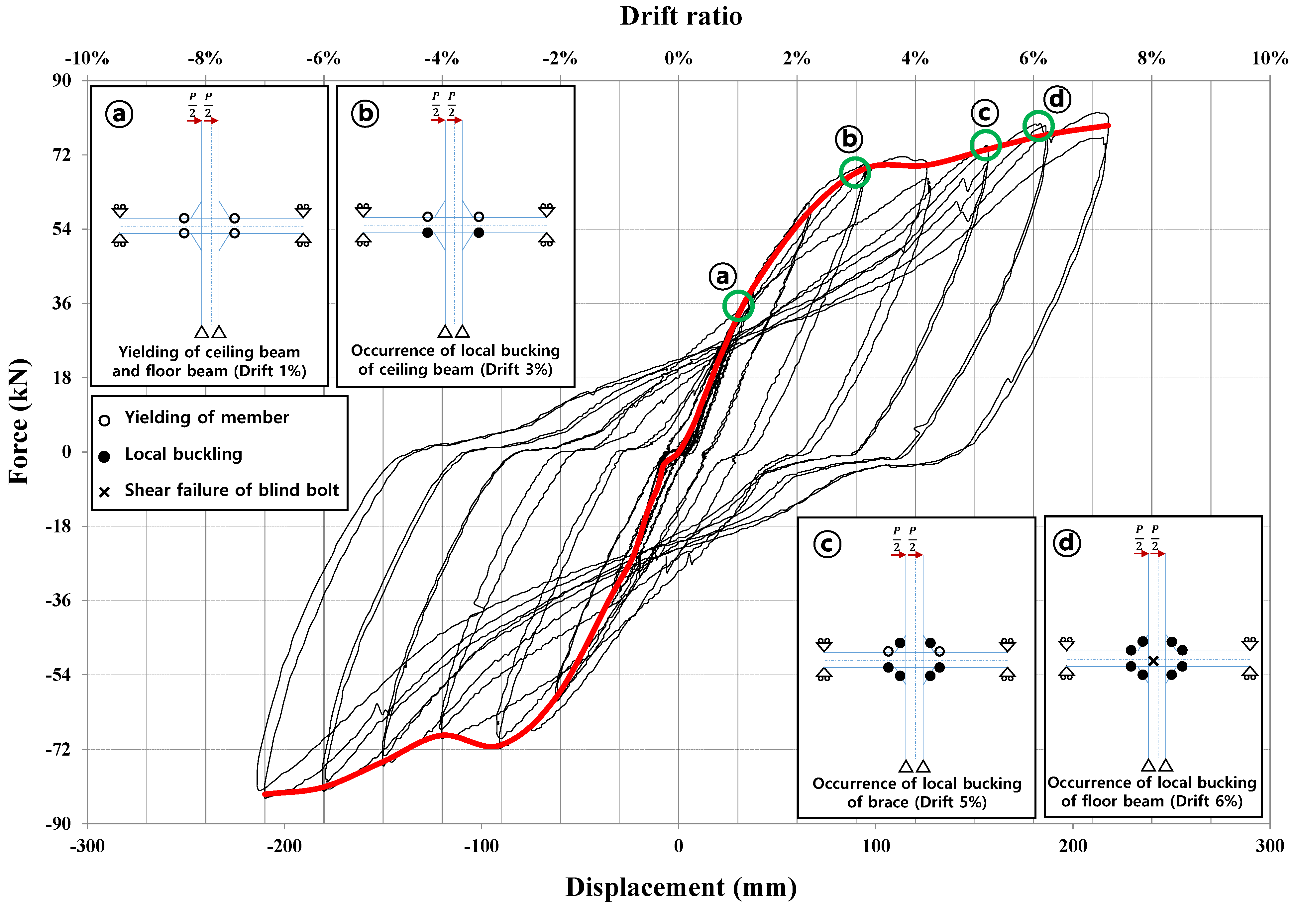
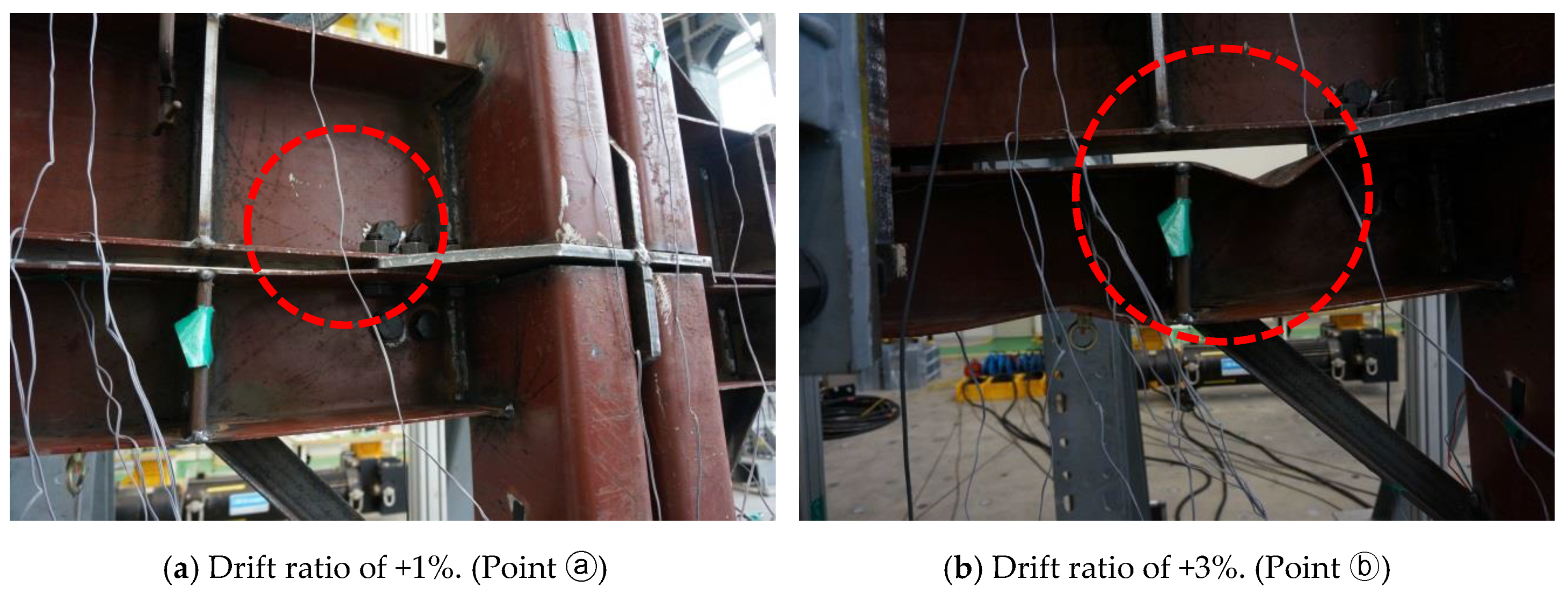
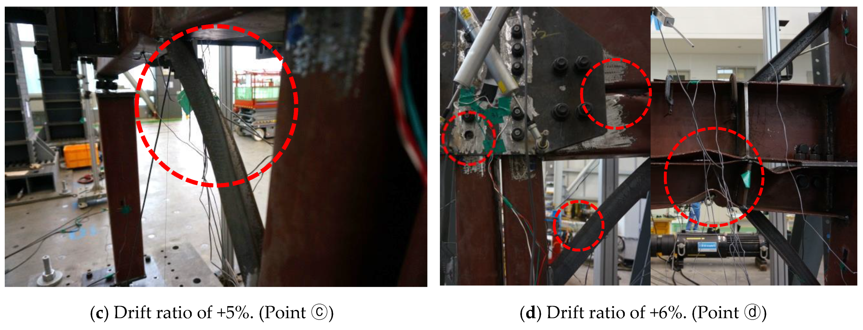
The hysteresis and backbone curves of Specimen IC_OB_B are plotted in Figure 13. It also indicates the failure sequence of main structural components of the specimen and the drift ratios at which each failure occurred. The photos of the failed structural components at major loading steps are provided in Figure 14. Both of the ceiling and floor beams yielded at the drift ratio of 1% (Figure 14a), and the local buckling at the flange and web of the ceiling beam was followed at the drift ratio of 3% (Figure 14b). The knee bracings started to yield at the drift ratio of 4.5% and they completely buckled at the drift ratio of 5% (Figure 14c). At the drift ratio of 6%, buckling occurred at the flange of the floor beam, and shear failure happened at one of the blinded bolts connecting the connection plate and lower module (Figure 14d).
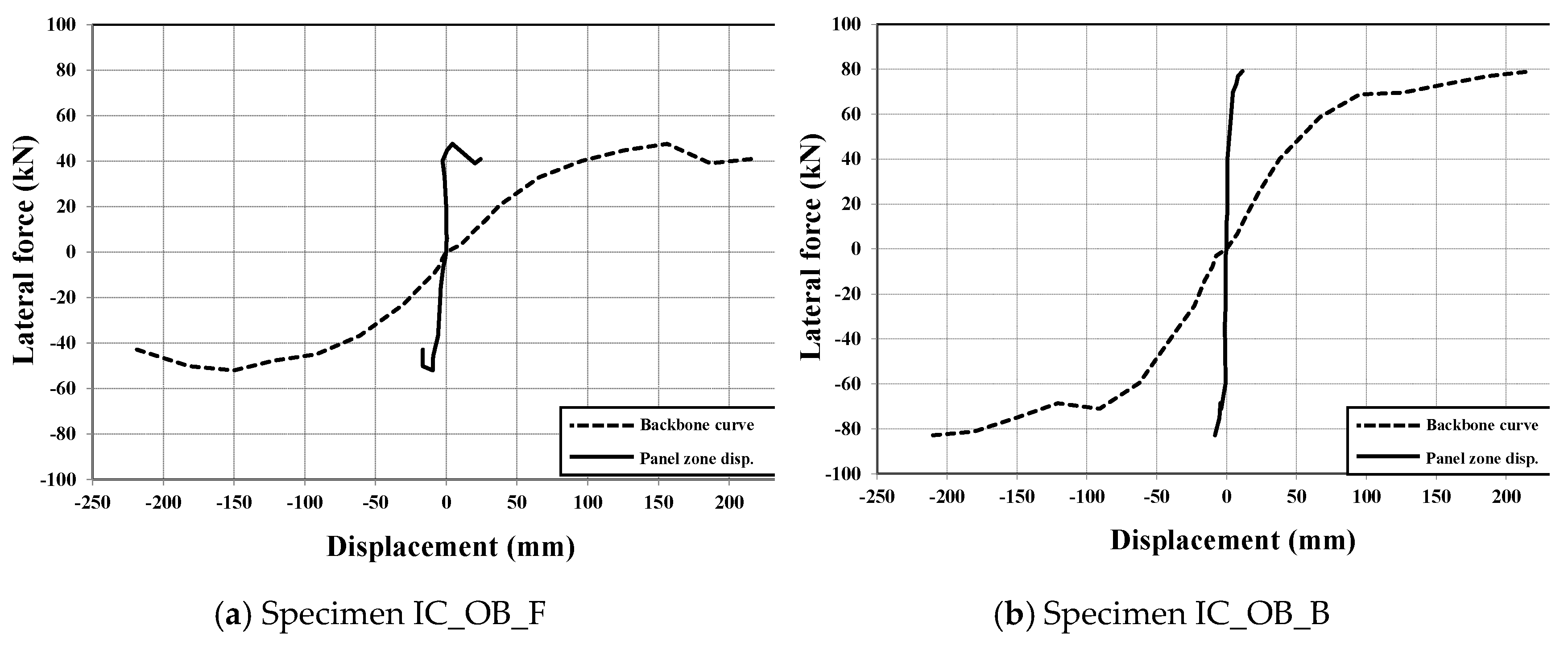
Figure 15 compares the backbone curves of the two specimens plotted in Figure 11 and Figure 13 with the corresponding panel zone displacement curves, due to shear deformation. The panel zone displacement was computed from the measured displacements by the LVDTs Nos. 4 and 5 by following the procedure discussed in the works of Fielding and Huang [23] and Rahiminia and Namba [24]. The results in the figure indicate that the maximum panel zone displacements of Specimens IC_OB_F and IC_OB_B are only 14.1% and 5.7% of the entire lateral displacements obtained from the corresponding backbone curves, respectively. This implies that the modular panel zone proposed in this study remains in the linear elastic range during most of the hysteresis procedure, and thus it has a sufficient level of strength and stiffness so that no premature failure occurs in the panel zone. In addition, it can be seen from the result that the existence of the knee bracings is helpful to reduce the shear deformation of the modular panel zone since the maximum panel zone displacement of Specimen IC_OB_F is almost the half of that of Specimen IC_OB_B.
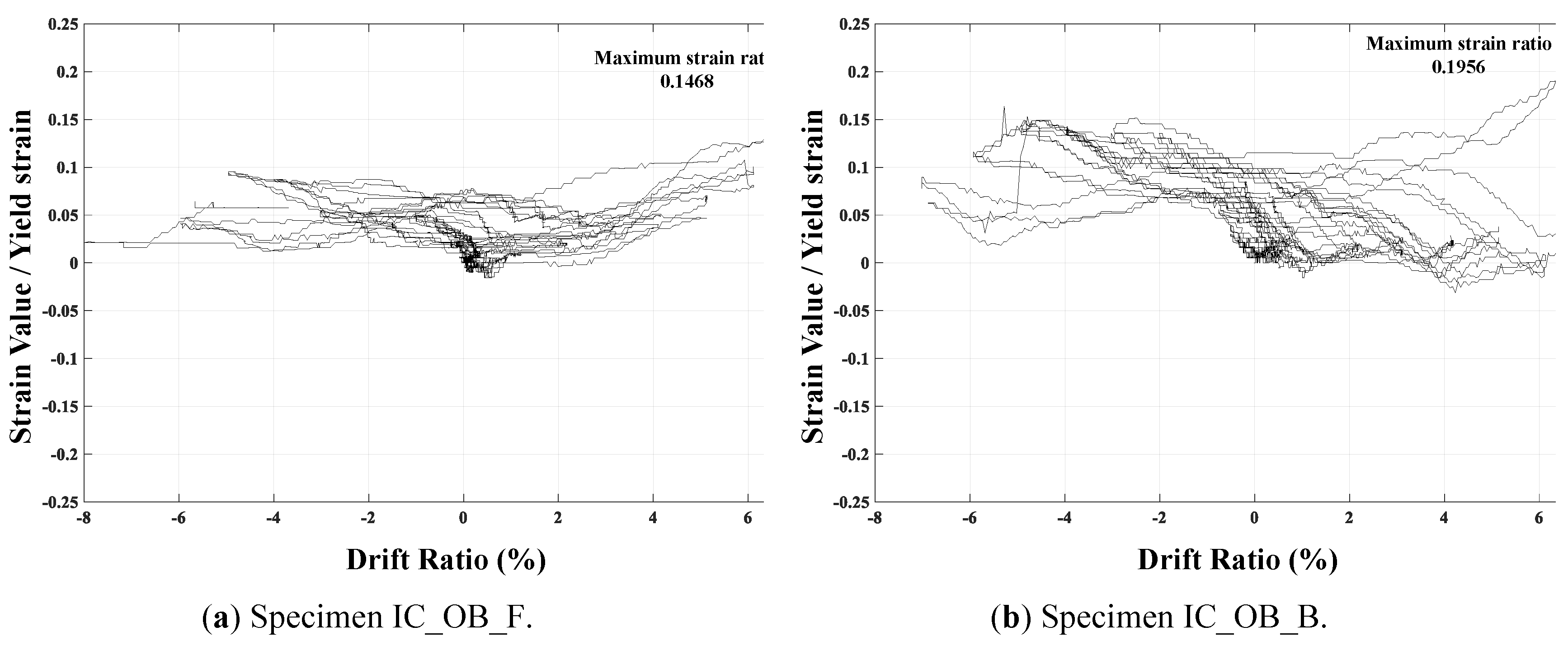
Figure 16 plots the ratio of the principle strain to the yield strain measured by the three strain gauges No. 21 to 23 during the entire hysteresis cycles. This figure reveals that the maximum values of the ratio are only 14.7% and 19.6% in the case of Specimens IC_OB_F and IC_OB_B, respectively. This indicates that the connection plate between modules did not yield in both specimens, and thus it retains sufficient strength to resist the lateral cyclic loading considered in this study.
Several important conclusions can be drawn from the test results. First, the proposed blind-bolted modular beam-column connection has a sufficient level of strength, and did not fail before the failure of other structural components. The shear failure of a single blind bolt was first observed at the drift of 7% only in IC_OB_B specimen. Second, the failure of beam members occurred before that of the column members, which reveals that the strong column-weak beam concept was successfully implemented in the proposed modular system. Third, the knee braces are very effective to increase the stiffness and strength of the proposed modular connection. For example, Specimen IC_OB_B reinforced with the knee braces retained approximately two times higher stiffness and 1.6 times higher strength than Specimen IC_OB_F. All of these conclusions demonstrate the effectiveness of the proposed blind-bolted modular beam-column system.
5. Simplified Analysis Model for the Proposed Steel Modular Connection
5.1. Modular Beam-Column Connection Modeling
As discussed in the introduction, a reasonable finite element model of the blind-bolted beam-column connection illustrated in Figure 2b is required for the design and analysis of the proposed modular structural system. Since frame elements are generally used in the finite element analysis of building structures, it is convenient to model the blind-bolted connection using only the frame elements, instead of other types of two- or three-dimensional finite elements, for simplicity of analysis. Based on this idea, we propose a simple, but effective connection model where the joints between the beam and column members are connected with each other by frame elements and their stiffness is determined such that it can represent the actual stiffness of the connection.
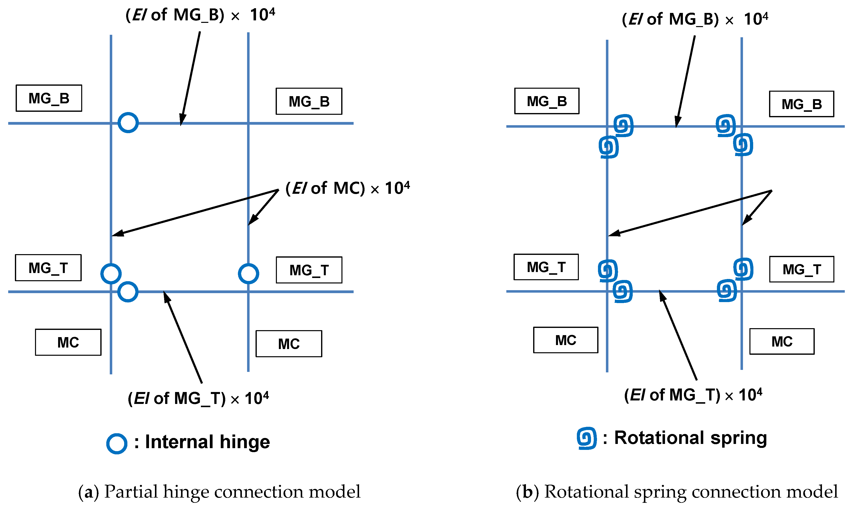
Figure 17a,b show two possible connection models satisfying the aforementioned conditions, which are the partial hinge and rotational spring connection models, respectively. In both cases, the four frame elements connecting the beam-column joints have very high stiffness. In the case of the partial hinge model, the stiffness of the blind-bolted connection is represented by four internal hinges, and thus this model does not require any additional material parameters. Although this model is simple, it is questionable if its stiffness can accurately represent the actual stiffness of the connection. Furthermore, it may result in an asymmetric distribution of internal forces and moments even if both the geometry of the structure and boundary conditions are symmetric. In contrast, the stiffness of the rotational spring connection is represented by the use of eight identical rotational springs inserted into the connecting frames, as shown in Figure 17b, and their stiffness can be determined from the experimental results.
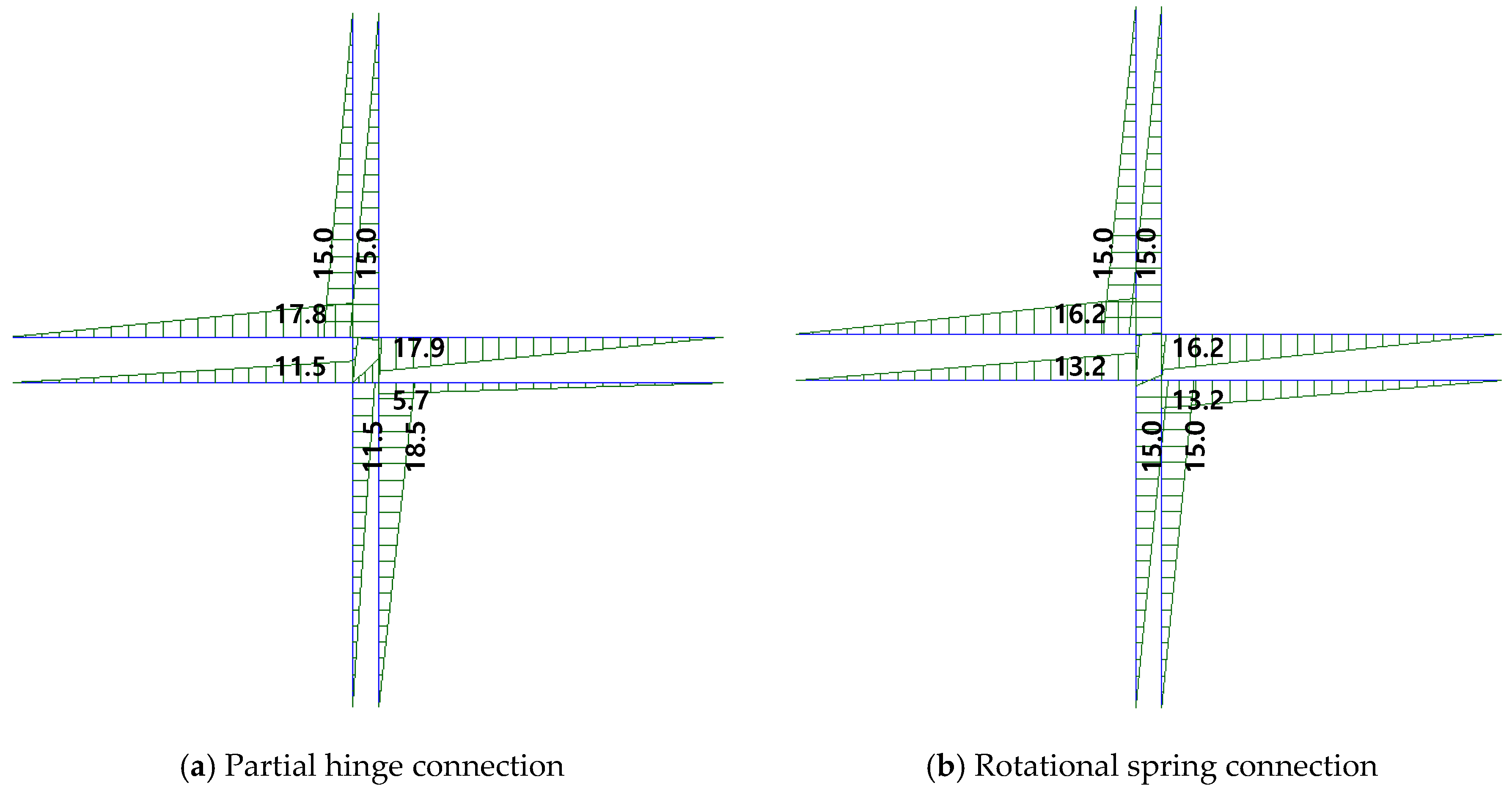
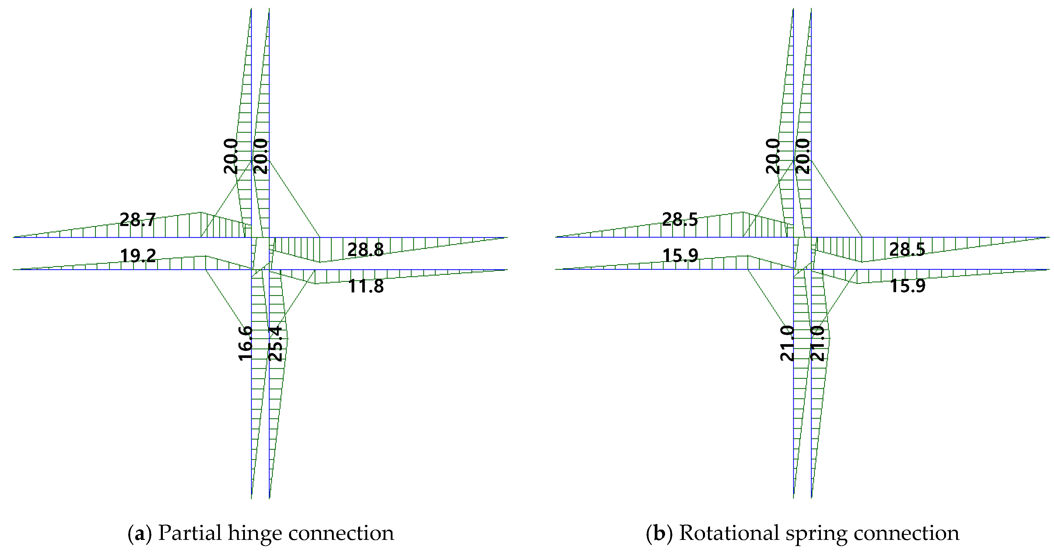
Since all of the member geometry, force and support conditions are symmetric with respect to the center line of the double main columns in both of the specimens, the distribution of internal forces also must be symmetric. Figure 18 shows the linear elastic internal bending moment distributions of the structural analysis model for IC_OB_F specimen utilizing the two types of the connection model when the lateral load (P) of 20 kN is applied. The results in the figure indicate that the moment distribution of the analysis model with the rotational spring connection is symmetric with respect to the double main column centerline, while the moment distribution of the model with the partial hinge connection is not. A similar result can be found from Figure 19, which shows the moment distribution of IC_OB_B specimen. Considering this result, the rotational hinge model is adopted to evaluate the structural performance of the proposed modular system in this study.
5.2. Validation of the Proposed Connection Model
This section proposes a simplified finite element model based on the rotational spring connection discussed in Section 5.1 and performs push-over analysis for the two test specimens using the well-known finite element package MIDAS Gen [25]. Its results are compared with the backbone curves of the two specimens plotted in Figure 11 and Figure 13, respectively, and the effectiveness of the proposed finite element model is validated.
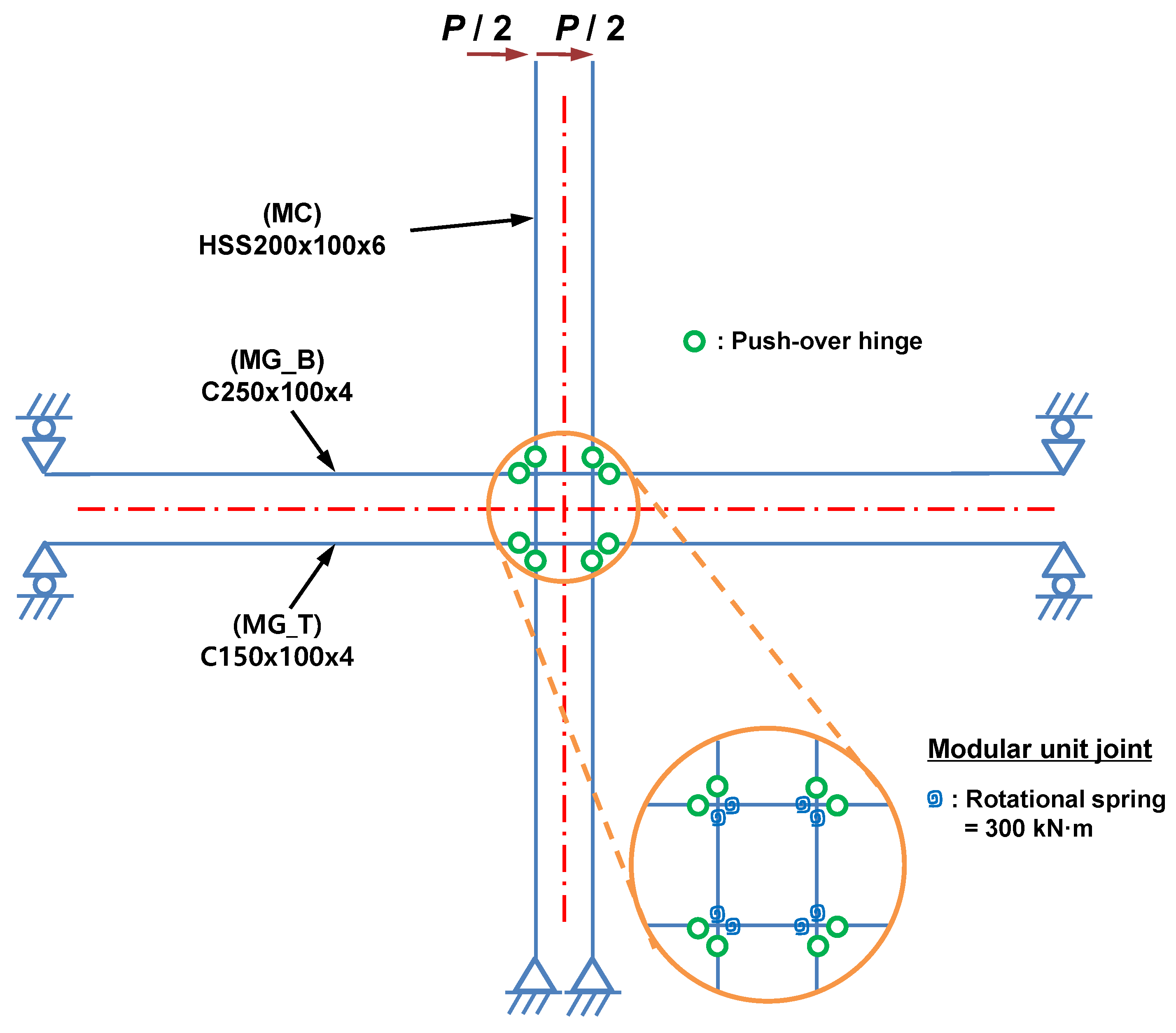
Figure 20 presents a finite element model for the push-over analysis of IC_OB_F specimen. In this model, the modular unit joint is composed of the rotational spring connection discussed in the previous section and the eight push-over hinges, which are included to simulate the various failure modes of the beam and column members observed in the test. It is assumed that the components of the rotational spring connection, which are the eight rotational springs and four connecting frames with high bending stiffness, remain in the linear elastic range during the entire push-over analysis since the failure of any of these components was not observed during the test as discussed in Section 4. The stiffness of the rotational spring is determined as 300 kN·m such that the initial stiffness of the load-displacement curve obtained by the push-over analysis is identical to that of the backbone curve.
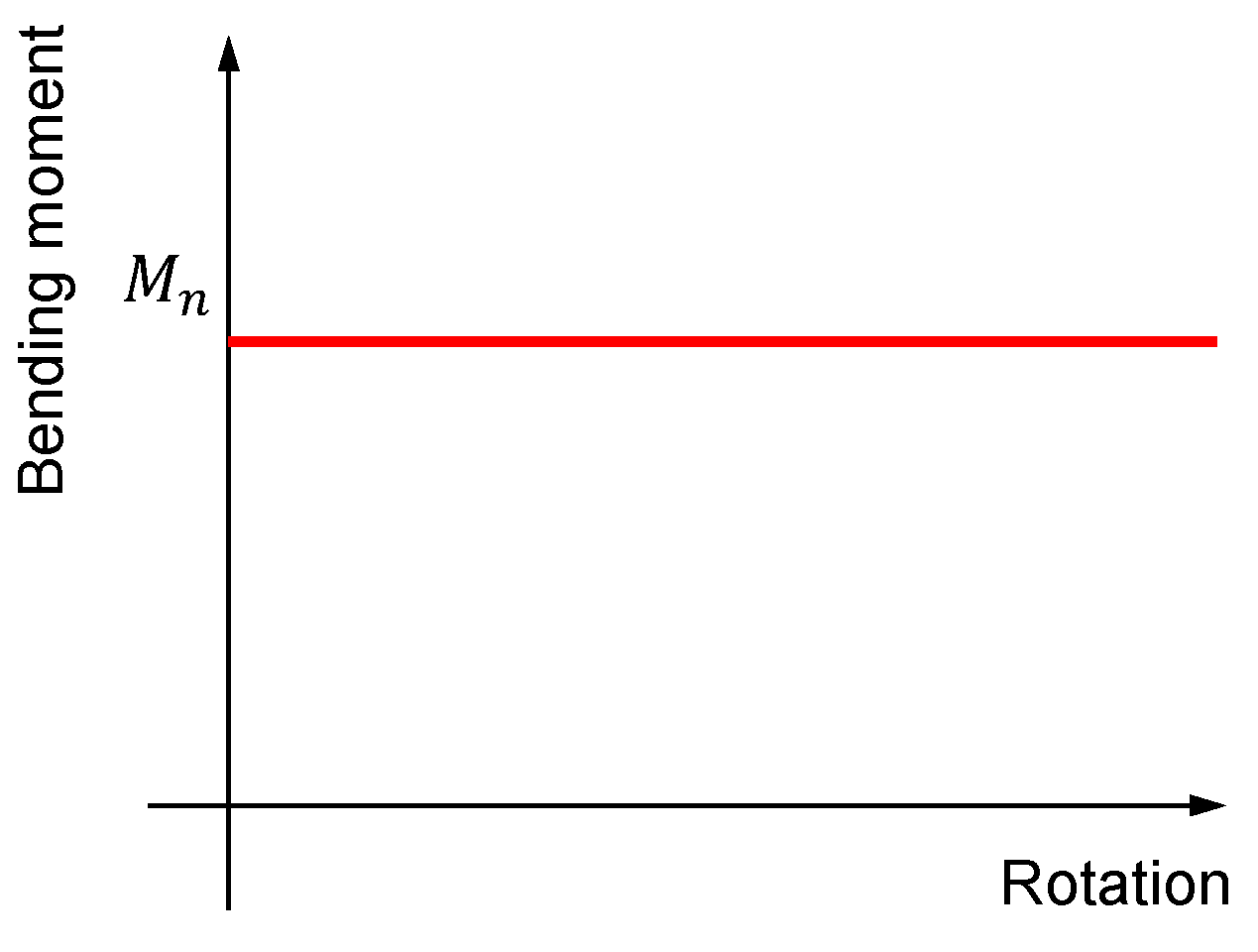
Figure 21 shows the bending moment-rotation relation adopted in the push-over hinges of the modular unit joint. It can be seen from the figure that a plastic hinge is formed if the internal bending moment of the section reaches its nominal bending moment strength (Mn), instead of its plastic moment strength (Mp). This relation is adapted to consider the local buckling failure that occurred in several members during the test, as reported in Section 4.2. Table 5 lists the plastic and nominal moment strengths of the beam and column members used in the test specimen, which are computed according to the load and resistance factor design (LRFD) code [26]. It indicates that the column section (MC) is non-compact and both of the floor (MG_B) and ceiling beam (MG_T) sections are slender, respectively. The yield strength of each member is taken from the test values listed in Table 2.
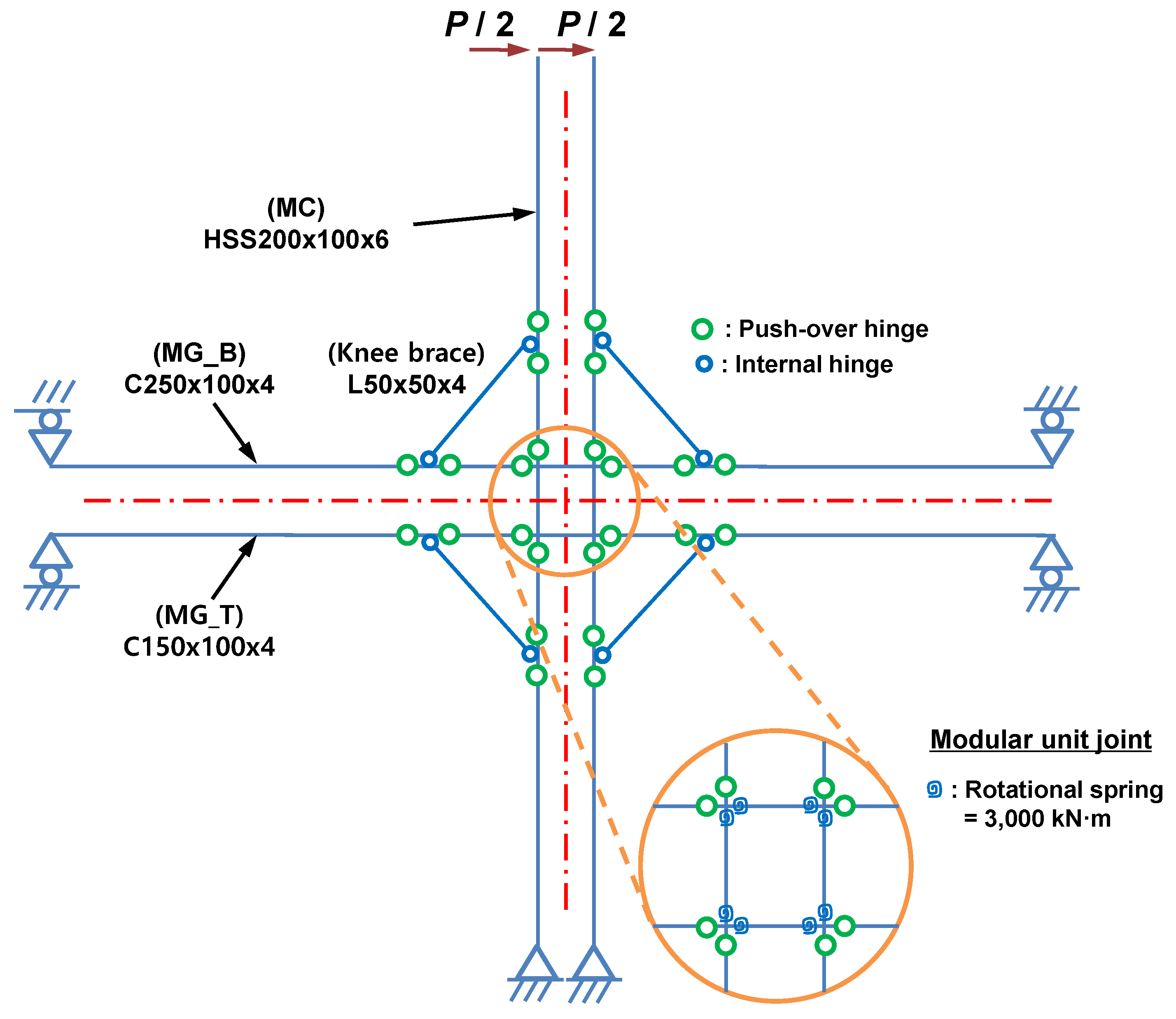
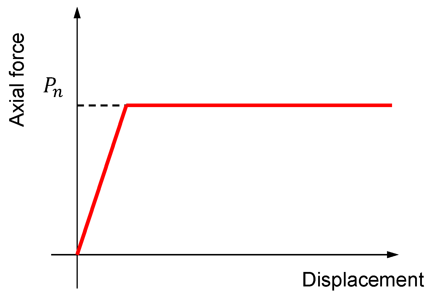
Figure 22 shows the finite element model for the push-over analysis of IC_OB_B specimen. It is identical with the model, shown in Figure 20, except that four knee brace members with the same cross-section are added at each corner between the beam and column members. The compressive force-displacement relation for the knee brace member is given in Figure 23, and it indicates that the member fails if its internal axial force reaches its nominal compressive strength, not its plastic compressive strength, as similar to the bending moment-rotation relation, shown in Figure 21. Table 6 lists the plastic and nominal compressive strengths of the knee brace, which shows that the knee brace section is slender. In this model, the stiffness of the rotational spring is determined to be 3,000 kN·m, by following the same approach used in the specimen without the knee braces.
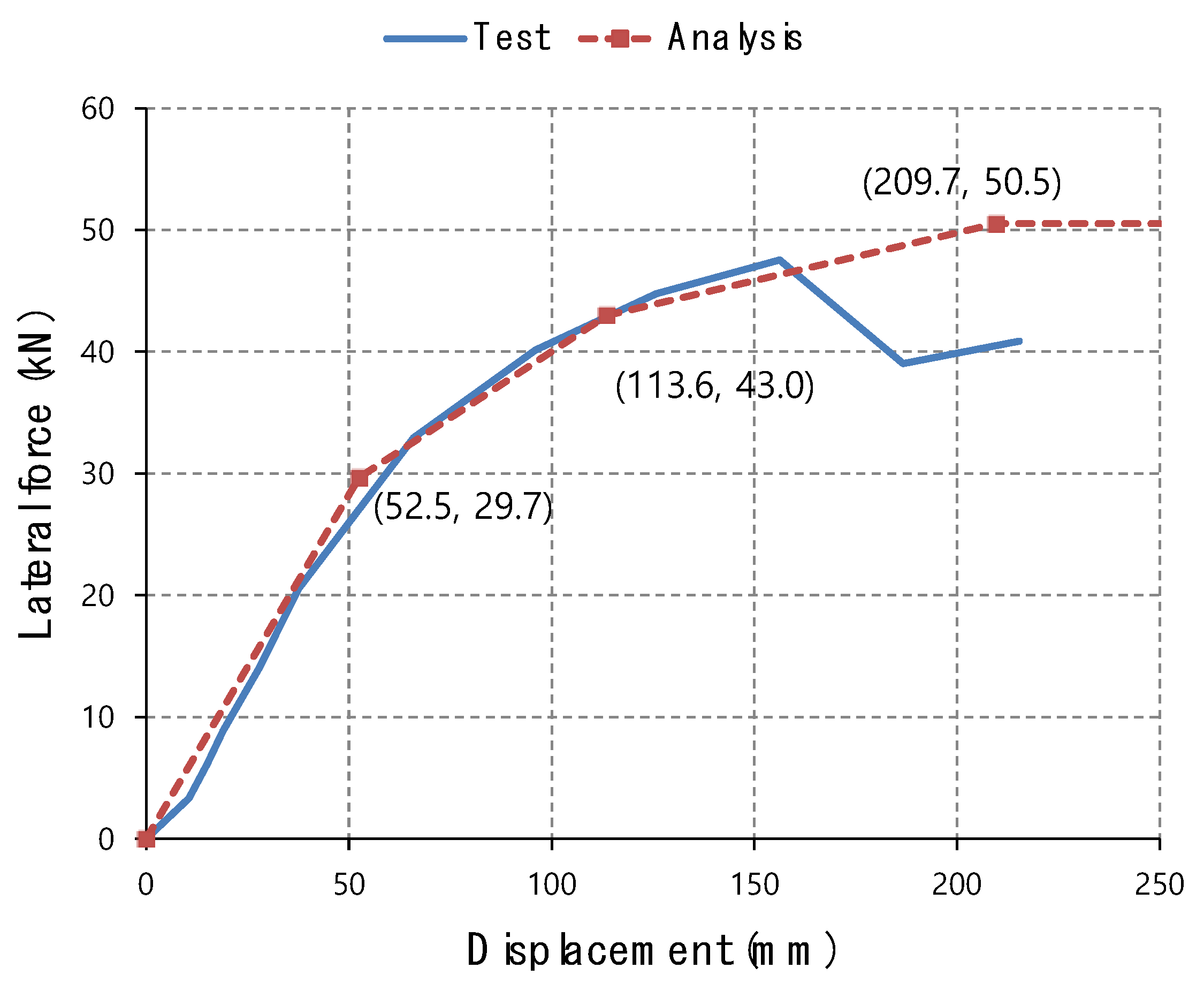
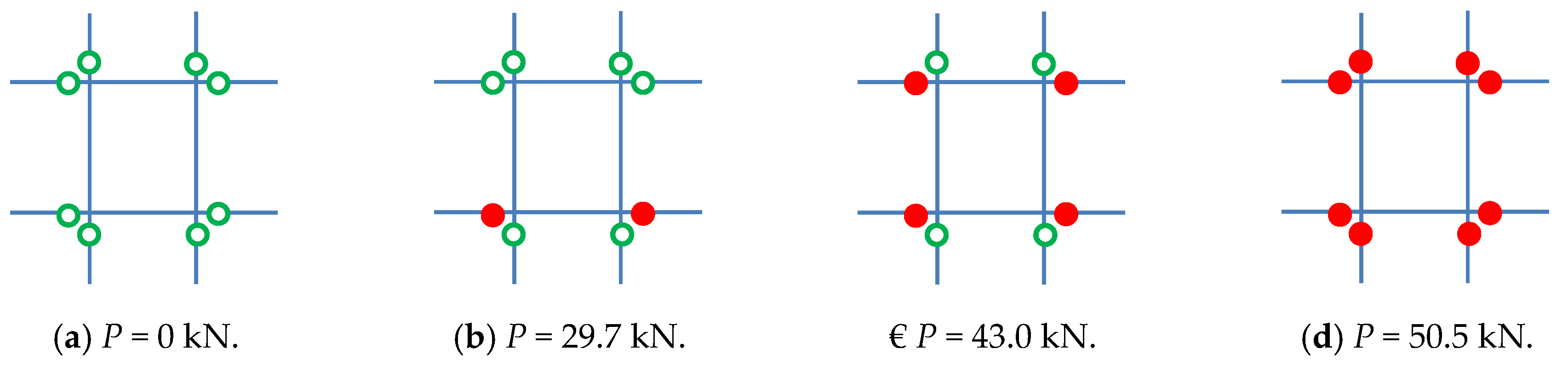
Figure 24 plots the lateral force-displacement curves that are obtained from the test and push-over analysis for Specimen IC_OB_F. This indicates that the result of the push-over analysis is well-matched with that of the test. The sequence and location of the plastic hinge formation in the push-over analysis is illustrated in Figure 25. The lateral force value corresponding to each plastic hinge formation is represented by a square symbol in Figure 24. It can be seen from the figure that plastic hinges are sequentially formed in the ceiling beam, floor beam and column. Although plastic hinge formation in the floor beam, shown in Figure 25b, was not observed in the test, the overall failure sequence of the push-over analysis is similar to the failure modes, shown in Figure 12.
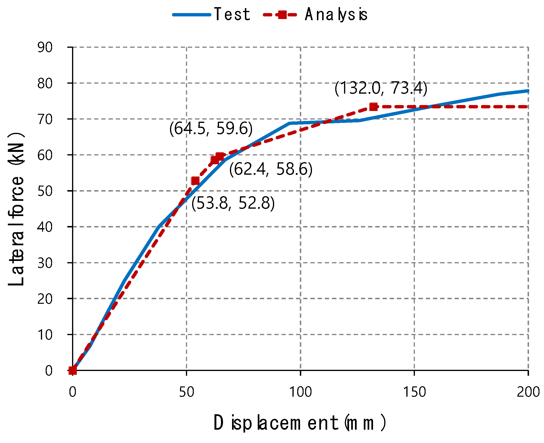
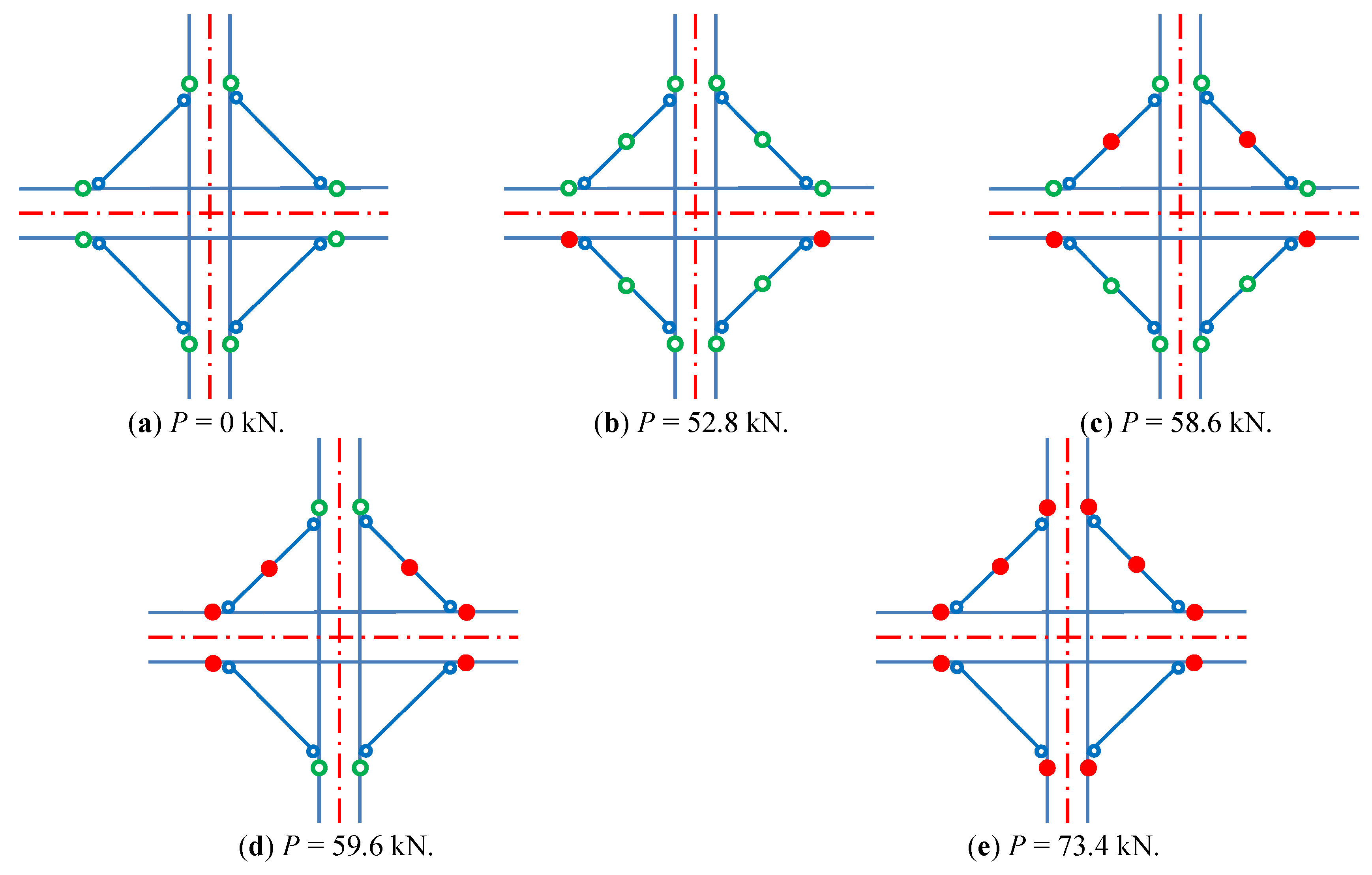
Similarly, the lateral force-displacement curves of Specimen IC_OB_B obtained from the test and push-over analysis are plotted in Figure 26. Considering the simplicity of the proposed analysis model, the two results are again quite well-matched by each other. Figure 27 illustrates the sequence of the plastic hinge formation and knee brace failure in the push-over analysis, which is quite similar to the failure modes, shown in Figure 14. All these results demonstrate that the proposed push-over analysis model based on the rotational spring connection is able to accurately predict the structural behavior of the blind-bolted beam-column modular connection.
6. Conclusions
In this study, a new steel frame modular system with blind-bolted modular connections was suggested, and its structural performance was investigated through experimental and analytical work. The new modular system was designed the strength of its beam members is considerably lower than that of its column members to implement the strong column-weak beam concept. Two types of specimens were designed and tested. One of the two specimens has four knee brace members to increase the bending stiffness of the connection, while the other does not have these components. A simplified analytical model for the modular beam-column connection was proposed and its effectiveness was validated by performing its push-over analysis and comparing its results with the test results. The main conclusions of this paper are as follows:
(1) The proposed blind-bolted modular beam-column connection has a sufficient level of strength. The test results showed that it did not fail before the failure of other structural components and the shear failure of a single blind bolt was first observed at the drift of 7% only in the test specimen with knee braces.
(2) The failure of beam members occurred before that of the column members, which reveals that the strong column-weak beam concept was successfully implemented in the proposed modular system.
(3) The knee braces are very effective to increase the stiffness and strength of the proposed modular connection. The test results indicate that the specimen with the knee braces retained approximately 2 times higher stiffness and 1.6 times higher strength than the one without them.
(4) The push-over analysis results demonstrate that the simplified connection model utilizing rotational springs is able to accurately predict the structural behavior of the proposed blind-bolted beam-column modular connection.
Currently, we are developing a method to estimate the stiffness of the rotational springs by performing more tests on the proposed modular connection and analyzing its detailed three-dimensional nonlinear finite element model.
Author Contributions
In this paper, B.-H.C. and H.K. proposed the main concept of the new frame modular connection; B.-H.C. prepared the experimental program to investigate its structural performance and made a contribution to the implementation of the experimental program. J.-S.L. analyzed the test results and prepared the tables and figures included in the paper; D.-J.K. developed a simplified analytical model for the modular connection and wrote the entire manuscript.
Acknowledgments
This research was supported by a grant from the National Research Foundation of Korea. (Grant number: NRF-2016 R1D1A1B01010615).
Conflicts of Interest
The authors declare no conflict of interest.
References
- Lawson, R.M.; Ogden, R.G. “Hybrid” light steel panel and modular systems. Thin-Walled Struct. 2008, 46, 720–730. [Google Scholar] [CrossRef]
- Lawson, R.M.; Ogden, R.G.; Bergin, R. Application of modular construction in high-rise buildings. ASCE J. Archit. Eng. 2012, 18, 148–154. [Google Scholar] [CrossRef]
- Oh, S.; Cho, B.-H.; Kim, D.-J. Development of an exportable modular building system by integrating quality function deployment and TRIZ method. J. Asian Archit. Build. Eng. 2017, 16, 535–542. [Google Scholar] [CrossRef]
- Cho, B.-H.; Kim, D.-J.; Ha, T. Systematic Approach for the Design of Modular Military Housing Units Using Six-Sigma. Scientia Iranica 2019. in publication process. [Google Scholar] [CrossRef]
- Lawson, R.M.; Ogden, R.; Goodier, C. Design in Modular Construction; CRC Press: Boca Raton, FL, USA, 2014. [Google Scholar]
- Generalova, E.M.; Viktor, P.G.; Kuznetsova, A.A. Modular buildings in modern construction. Procedia Eng. 2016, 153, 167–172. [Google Scholar] [CrossRef]
- Jackson, J. Chinese Builders Construct 30-Story Hotel in 15 Days. Available online: http://newsfeed.time.com/2012/01/10/chinese-builders-construct-30-story-hotel-in-15-days (accessed on 10 January 2012).
- Liu, X.; Zhang, A.; Ma, J.; Tan, Y.; Bai, Y. Design and model test of a modularized prefabricated steel frame structure with inclined braces. Adv. Mater. Sci. Eng. 2015, 2015, 291481. [Google Scholar] [CrossRef]
- Liu, X.C.; Xu, A.X.; Zhang, A.L.; Ni, Z.; Wang, H.X.; Wu, L. Static and seismic experiment for welded joints in modularized prefabricated steel structure. J. Constr. Steel Res. 2015, 112, 183–195. [Google Scholar] [CrossRef]
- Liu, X.C.; Pu, S.H.; Zhang, A.L.; Xu, A.X.; Ni, Z.; Sun, Y.; Ma, L. Static and seismic experiment for bolted-welded joint in modularized prefabricated steel structure. J. Constr. Steel Res. 2015, 115, 417–433. [Google Scholar] [CrossRef]
- Hong, S.-G.; Cho, B.-H.; Chung, K.-S.; Moon, J. Behavior of framed modular building system with double skin steel panels. J. Constr. Steel Res. 2011, 67, 936–946. [Google Scholar] [CrossRef]
- Deng, E.-F.; Zong, L.; Ding, Y.; Dai, X.-M.; Lou, N.; Chen, Y. Monotonic and cyclic response of bolted connections with welded cover plate for modular steel construction. Eng. Struct. 2018, 167, 407–419. [Google Scholar] [CrossRef]
- Hisham, S.B.; Goel, S.C. Special truss moment flames with Vierendeel middle panel. Eng. Struct. 1995, 17, 352–358. [Google Scholar]
- Chao, S.-H.; Goel, S.C. Performance-based plastic design of special truss moment frames. AISC Eng. J. 2008, 45, 127–150. [Google Scholar]
- Ölmez, H.D.; Topkaya, C. A numerical study on special truss moment frames with Vierendeel openings. J. Constr. Steel Res. 2011, 67, 667–677. [Google Scholar] [CrossRef]
- Longo, A.; Montuori, R.; Piluso, V. Theory of plastic mechanism control of dissipative truss moment frames. Eng. Struct. 2012, 37, 63–75. [Google Scholar] [CrossRef]
- Annan, C.D.; Youssef, M.A.; el Naggar, M.H. Experimental evaluation of the seismic performance of modular steel-braced frames. Eng. Struct. 2009, 31, 1435–1446. [Google Scholar] [CrossRef]
- Klippel, S. Recent design developments with blind mechanically operated bolt systems for use with hollow section steelwork. J. Constr. Steel Res. 1998, 1, 267–268. [Google Scholar] [CrossRef]
- Barnett, T.; Tizani, W.; Nethercot, D. The practice of blind bolting connections to structural hollow sections: A review. Steel Compos. Struct. 2001, 1, 1–16. [Google Scholar] [CrossRef]
- Málaga-Chuquitaype, C.; Elghazouli, A.Y. Component-based mechanical models for blind-bolted angle connections. Eng. Struct. 2010, 32, 3048–3067. [Google Scholar] [CrossRef]
- Wang, Z.Y.; Tizani, W.; Wang, Q.Y. Strength and initial stiffness of a blind-bolt connection based on the T-stub model. Eng. Struct. 2010, 32, 2505–2517. [Google Scholar] [CrossRef]
- ASTM Standard A370-12a. Standard Test Methods and Definitions for Mechanical Testing of Steel Products; Annual Book ASTM Standards: West Conshohocken, PA, USA, 2012. [Google Scholar]
- Fielding, D.J.; Huang, J.S. Shear in steel beam-to-column connections. Weld. J. 1971, 50, 313–326. [Google Scholar]
- Rahiminia, F.; Namba, H. Joint panel in steel moment connections, Part 1: Experimental tests results. J. Constr. Steel Res. 2013, 89, 272–283. [Google Scholar] [CrossRef]
- MIDAS/Gen. MIDAS/Gen Ver.8.7 Analysis and Design Manual; MIDAS Information Technology, Co., Ltd.: Seongnam, Republic of Korea, 2018. [Google Scholar]
- American Institute of Steel Construction. Manual of Steel Construction, Load and Resistance Factor Design, 14th ed.; AISC: Chicago, IL, USA, 2010. [Google Scholar]
Figure 1.
Modular unit composition.

Figure 2.
Module-to-module connection details.

Figure 3.
Fastening process of the blind bolt.

Figure 4.
Blind bolt details.

Figure 5.
Determination of the test setup.

Figure 6.
Details of specimen IC_OB_F.

Figure 7.
Details of specimen IC_OB_B.

Figure 8.
Specimen setting.

Figure 9.
Cyclic loading applied to the specimens.

Figure 10.
Schematic illustration of a linear variable differential transducer (LVDT) and strain gauge setup.
Figure 10.
Schematic illustration of a linear variable differential transducer (LVDT) and strain gauge setup.

Figure 11.
Hysteresis and backbone curves of specimen IC_OB_F.

Figure 12.
Failure sequence of Specimen IC_OB_F.

Figure 13.
Hysteresis and backbone curves of specimen IC_OB_B.

Figure 14.
Failure sequence of Specimen IC_OB_B.


Figure 15.
Displacements due to shear deformation of the panel zone connection plate.

Figure 16.
Principal strain of the connection plate measured by strain gauges No. 21 to 23.

Figure 17.
Modular beam-column connection modeling.

Figure 18.
Linear elastic moment distribution of IC_OB_F specimen at P = 20 kN. (unit: kN·m).

Figure 19.
Linear elastic moment distribution of IC_OB_B specimen at P = 40 kN. (unit: kN·m).

Figure 20.
Push-over analysis model of IC_OB_F specimen. (unit: mm).

Figure 21.
Bending moment-rotation relation of the beam and column members for push-over analysis.

Figure 22.
Push-over analysis model of IC_OB_B specimen. (unit: mm).

Figure 23.
Compressive force-displacement relation of the knee brace member for push-over analysis.

Figure 24.
Validation of the analysis model for IC_OB_F specimen.

Figure 25.
Failure procedure of IC_OB_F specimen.

Figure 26.
Validation of the analysis model for IC_OB_B specimen.

Figure 27.
Failure procedure of IC_OB_B specimen.


Table 1.
Main features of two test specimens. (unit: mm).
| Specimen | IC_OB_F | IC_OB_B | |
|---|---|---|---|
| Frame members | Column | HSS200×100×6 | |
| Floor beam | C250×100×4 | ||
| Ceiling beam | C150×100×4 | ||
| Knee brace | L50×50×4 | N/A | |
| Connection components | Connection plate | PL-12 | |
| Front-side connection bolts | 10 F13T M20 blind bolts + 8 F10T M20 H/T bolts | ||
| Detail of module to module connection |  |  | |
Table 2.
Material properties of the structural members used in the test specimens.
| Structural Member | Steel Type | Thickness (mm) | Yield Strength (MPa) | Ultimate Strength (MPa) |
|---|---|---|---|---|
| Bracing | SS400 | 4 | 334.1 | 466.4 |
| Ceiling beam | SM490 | 4 | 395.1 | 518.7 |
| Floor beam | 4 | 459.4 | 579.7 | |
| Column | 6 | 372.6 | 549.0 |
Table 3.
Material properties of blind bolts.
| Diameter of Bolt Hole (mm) | Diameter of Core Pin (mm) | Ultimate Strength of Core Pin (MPa) | Ultimate Strength of Grip Sleeve (MPa) | |
|---|---|---|---|---|
| M20 | 21.0~22.0 | 16.8 | 1300 | 960 |
Table 4.
Test results.
| Specimen | Loading Direction | Member | At Occurrence of First Yielding | At Peak Load | |||||
|---|---|---|---|---|---|---|---|---|---|
| Drift Ratio | Displacement Value (mm) | Load Value (kN) | Stiffness (kN/m) | Drift Ratio | Displacement Value (mm) | Load Value (kN) | |||
| IC_OB_F | Positive | Ceiling beam | 2.16% | 66.0 | 32.92 | 499.0 | 5.17% | 156.3 | 48.27 |
| Negative | Ceiling beam | −2.71% | −82.8 | −44.01 | 531.8 | −4.88% | −149.0 | −52.34 | |
| IC_OB_B | Positive | Ceiling/Floor beams | 1.02% | 31.2 | 33.47 | 1073.8 | 6.97% | 212.6 | 82.30 |
| Negative | Ceiling beam | −1.05% | −31.9 | −35.35 | 1106.8 | -6.88% | -210.0 | -83.78 | |
Table 5.
Plastic and nominal moment capacity of the beam and column members of the test specimen.
| Member | Mp (kN·m) | Mn (kN·m) | Width-thickness Ratio | λp | λr | Slenderness | |
|---|---|---|---|---|---|---|---|
| MC (HSS200×100×6) | 50.7 | 38.1 | Flange | 31.3 | 25.9 | 32.4 | Non-compact |
| Web | 14.7 | 56.1 | 132.1 | Compact | |||
| MG_B (C250×100×4) | 72.1 | 38.8 | Flange | 25.0 | 7.9 | 20.9 | Slender |
| Web | 60.5 | 78.5 | 128.2 | Compact | |||
| MG_T (C150×100×4) | 31.0 | 20.1 | Flange | 25.0 | 8.5 | 22.5 | Slender |
| Web | 35.5 | 84.6 | 128.2 | Compact | |||
Table 6.
Plastic and nominal compressive strength of the knee brace of IC_OB_B specimen.
| Member | Pp (kN) | Pn (kN) | KL/r | Width-thickness Ratio | λp | λr | Slenderness |
|---|---|---|---|---|---|---|---|
| Knee brace (L50×50×4) | 128.3 | 111.6 | 36.4 | 12.5 | 11.0 | 22.3 | Slender |
© 2019 by the authors. Licensee MDPI, Basel, Switzerland. This article is an open access article distributed under the terms and conditions of the Creative Commons Attribution (CC BY) license (http://creativecommons.org/licenses/by/4.0/).
Share and Cite
MDPI and ACS Style
Cho, B.-H.; Lee, J.-S.; Kim, H.; Kim, D.-J. Structural Performance of a New Blind-Bolted Frame Modular Beam-Column Connection under Lateral Loading. Appl. Sci. 2019, 9, 1929. https://doi.org/10.3390/app9091929
AMA Style
Cho B-H, Lee J-S, Kim H, Kim D-J. Structural Performance of a New Blind-Bolted Frame Modular Beam-Column Connection under Lateral Loading. Applied Sciences. 2019; 9(9):1929. https://doi.org/10.3390/app9091929
Chicago/Turabian StyleCho, Bong-Ho, Jae-Sub Lee, Hongjin Kim, and Dae-Jin Kim. 2019. "Structural Performance of a New Blind-Bolted Frame Modular Beam-Column Connection under Lateral Loading" Applied Sciences 9, no. 9: 1929. https://doi.org/10.3390/app9091929
Note that from the first issue of 2016, this journal uses article numbers instead of page numbers. See further details here.