1. Introduction
In the last few decades, a number of liquid-crystal (LC)-based devices have been demonstrated with functionalities such as phase shifters, filters, modulators, and polarizers, in the terahertz (THz) frequency range [
1,
2,
3,
4]. Recently, we demonstrated an electrically tuned LC-based THz phase shifter with high transmittance and driving voltages compatible with complementary metal–oxide–semiconductor (CMOS) and thin-film transistor (TFT) technologies [
5]. The key to the referred work [
5] is nanostructured indium tin oxide (ITO) as a transparent conducting electrode (TCE). Only a few TCEs have been explored at THz frequencies in contrast with those in visible frequencies [
6]. It should be noted that ITO film is not suitable as a THz-TCE layer because of its high absorption of THz waves [
7]. To date, graphene, ITO nano-whisker (NW), and dimethylsulfoxide (DMSO)-doped poly(3,4-ethylenedioxythiophene):poly(styrenesulfonate (PEDOT: PSS) thin layers have been successfully employed as TCE materials for THz device applications [
5,
8,
9,
10,
11]. Nanostructured TCEs such as graphene and ITO nano-whiskers are relatively difficult to prepare. In contrast, PEDOT: PSS films can be easily fabricated by spin coating [
12]. In a previous work, Ito et al. [
13] investigated THz phase imaging using an 800 µm thick homogeneous LC device using pristine PEDOT: PSS electrode layers and achieved a 360° phase shift at 2.5 THz. More than 75 V of bias, however, was needed to achieve a 90° phase shift. The THz transmittance and conductivity of PEDOT: PSS thin film doped with either dimethyl sulfoxide (DMSO) or ethylene glycol (EG) have also been investigated. Sun et al. [
14] reported that PEDOT: PSS thin films doped with 10% EG and with thicknesses between 34 and 102 nm exhibited transmission between 62% and 83% in the frequency range of 0.3–1.2 THz. Moreover, Yan et al. [
15] reported that 6% DMSO-doped PEDOT: PSS thin film with thicknesses between 31 and 129 nm showed transmission between 30% and 72% in the frequency range of 0.5–2.5 THz. The THz transmittance decreased significantly with the increasing thickness of PEDOT: PSS layers doped with either EG or DMSO. In addition, the PEDOT: PSS thin layer displayed trade-off behaviors in conductivity, surface roughness, adhesion to the substrate, and lack of uniformity to increased surface to volume ratio during deposition by the spin-coating process [
16]. Additional processes are needed to avoid the above-mentioned issues [
17]. Recently, Du et al. [
11] reported outstanding performances of homogeneously aligned LC-based THz phase shifters using DMSO-doped PEDOT: PSS as a TCE layer. The transmittance of this device, however, gradually decreased with frequency and became almost zero at 1.2 THz. This can be attributed to the fact that the transmittance of a homogenously aligned LC cell exhibits more explicit dependence on the wavelength [
18]. In related work, Sasaki et al. [
19] fabricated a THz polarization converter using a twisted nematic (TN) LC cell structure with pristine PEDOT/PSS films as TCE. A 1 mm thick TN cell was used and a driving voltage of approximately 15 V was applied to decrease the transmittance of the device to zero. However, there is no discussion in the paper of the performance of TN-LC cell as a phase shifter. The TN-LC cell has additional advantages with a faster response time, a transmittance performance less dependent on wavelength, and a performance less dependent on the angle of incidence. Therefore, this structure has been widely used in displays [
20]. Hence, it is worthwhile to study in detail the performance of TN-LC-based THz phase shifters using pristine PEDOT: PSS as a TCE layer. Furthermore, several new types of LC with high birefringence have recently been developed for THz applications, wherein the reduction of the cell thickness would be attractive. For example, the mixture 1825 LC (Institute of Chemistry, Military University of Technology, Warsaw, Poland) exhibits quite high birefringence (Δ
n ~0.38) at THz frequencies [
21]. Therefore, the thickness of LC can be reduced by more than 50% in comparison with the widely used E7 (Merck, KGaA, Darmstadt, Germany, Δ
n ~0.14 [
5]) and MDA-00-3461 (Δ
n ~0.2 [
8]), which both need to achieve a 90° phase shift at 1.2 THz. Moreover, the pristine PEDOT: PSS electrode layer, while the conductivity is lower than doped films, may be suitable enough to reorient the LC molecules properly prepared in such a TN-LC cell with reduced thickness and to achieve the 90° phase shift with reasonable driving and threshold voltage. Thus, a pristine PEDOT: PSS electrode-based TN-LC cell combined with LCs with high birefringence, such as mixture 1825, could be attractive for THz applications such as phase shifters.
For this paper, we first investigated the transmittance properties of spin-coated pristine PEDOT: PSS layers with different thicknesses for the frequency range of 0.2–1.2 THz. In addition, we measured the THz optical properties such as ordinary refractive index (no), extraordinary refractive index (ne), birefringence (Δn), absorption coefficient (α), and extinction coefficient (κ) of two types of LC, namely, MDA-00-3461 and mixture 1825, for use in the TN-LC--based THz phase shifters. Next, we demonstrated three different types of LC phase shifters using pristine PEDOT: PSS as TCE. Furthermore, we made a comparative study of TN-LC-based phase shifters with two different MDA-00-3461 thicknesses. Finally, we improved the TN-LC phase shifter performances using the mixture 1825 LC, which made possible the use of thinner cells. A figure of merit (FOM) was defined and used to compare the relative merit of LC THz phase shifters.
2. Materials and Methods
We selected the bare fused silica (~1 mm thick) as substrates to fabricate all the devices. All substrates were washed in acetone, isopropyl alcohol, and deionized water under ultrasonic agitation, then dried by using a nitrogen gun and hotplate, and subjected to cooling for half an hour. Three sets of samples were used in this investigation. The details of the fabrication process for all sets of samples are presented in the following paragraphs.
First set: pristine PEDOT: PSS (Agfa-S300, Taipei, Taiwan), with sheet resistance 216 ohm/square) with three different thicknesses were coated on substrates by spin coating and baked at approximately 130 °C for 12 min. One clean bare substrate was used for the reference to investigate the THz transmittance properties. The thickness of the pristine PEDOT: PSS films was controlled by the spin coater with a rotation speed 3000 rpm for 30 s.
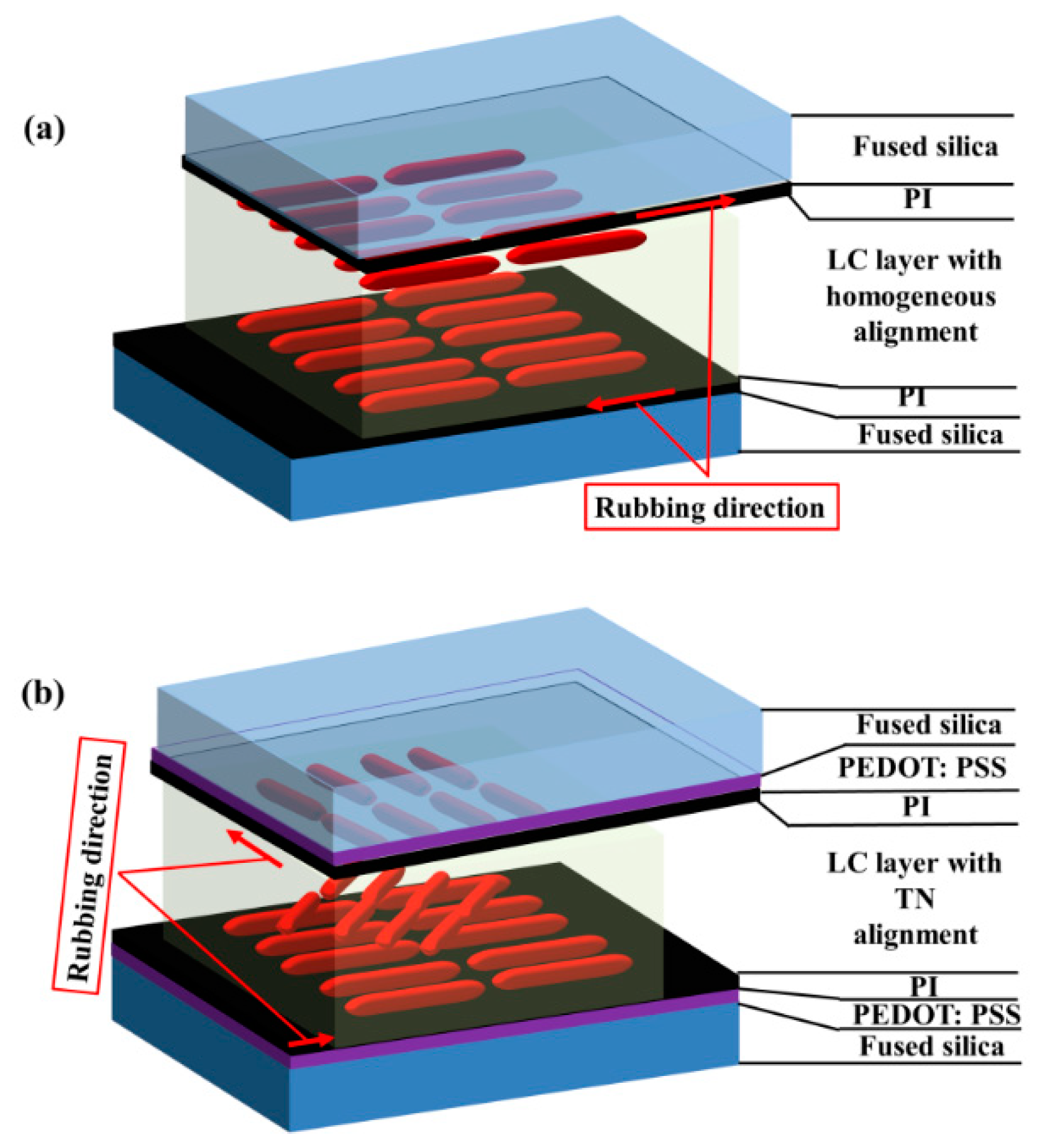
Second set: we prepared two types of LC cells (thickness ~250 µm), one with MDA-00-3461 and another with mixture 1825. A polyimide (PI) ~2 µm thin layer was spin coated on the TCE-coated substrates and baked for solvent evaporation. The mechanical rubbing process was applied on top of the PI layer after cooling. The two substrates for each LC cell were assembled together in anti-parallel orientation to form a cell with a homogeneous alignment. The cell gap was controlled by a Mylar film with a thickness of 250 μm. The details of a homogeneously aligned LC cell structure can be found in
Figure 1a. In addition, we prepared an empty cell as reference cell −1.
Third set: we prepared three types of LC THz phase shifters using the optimized thickness of pristine PEDOT: PSS films as TCEs. In this case, the pristine PEDOT: PSS layer was prepared on the substrate using the spin coating method. Substrate preparation was the same as that described for set 2. The two substrates were then assembled together with the rubbing direction in perpendicular orientation to each other, corresponding to the rubbing directions to form a cell with TN molecule alignment. Here, two TN-LC cells with thicknesses of 250 and 550 µm, respectively, were fabricated with injected MDA-00-3461 LC molecules. Another 250 µm thick TN-LC sample was fabricated with injected mixture 1825 LC molecules. The thickness of each cell was controlled by the thickness of the Mylar film. Moreover, we prepared an empty cell as reference cell −2. We defined the identity of the three types of TN-LC phase shifters as shown in
Table 1. A schematic illustration of the TN-LC THz phase shifter is shown in
Figure 1b.
A photoconductive antenna (PCA)-based transmission-type THz time-domain spectrometer (THz-TDS) as described in our previous works in the frequency range of 0.2–1.2 THz was used for characterization of the materials and devices in the THz frequency band [
23,
24].
For measurement of the THz optical constants of both types of LCs, the transmitted THz signal of the extraordinary wave was measured while the LC alignment direction of the sample was placed parallel to the THz field polarization, whereas the ordinary wave was measured by simply rotating the sample by 90°
. In addition, we measured the transmitted THz signals from the reference cell. For the details of the techniques and procedures used to extract all the parameters, please refer to our previous work [
23,
24]. In this study, the critical parameters such as the thickness of the sample and the reference were well taken into account. Furthermore, the parameters for the Fabry–Perot coefficients due to multiple reflections of the THz wave in the LC cell were taken into account.
3. Operational Principles
Previously, we analyzed LC THz phase shifters with a homogeneous alignment [
2,
5,
6,
8,
9,
10]. Basically, the analysis followed the treatment of Yeh and Gu [
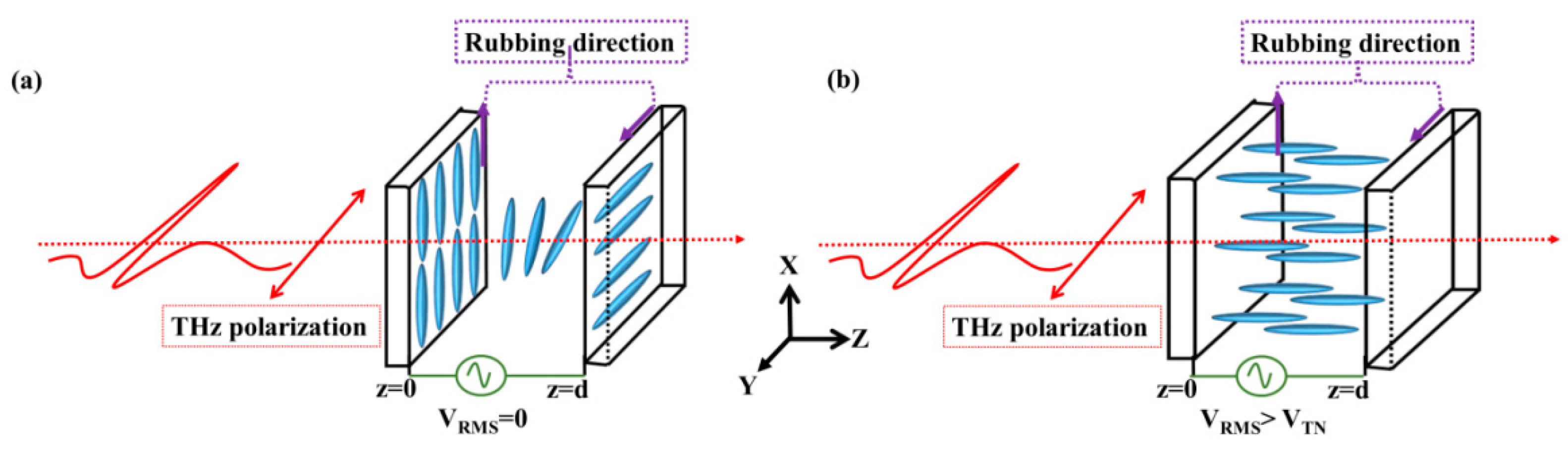
25]. The medium through which the THz wave propagates is assumed to be homogeneous, non-absorbent, and magnetically isotropic. This is an approximation, as LC and fused silica and the TCE and alignment layers exhibit a small yet non-negligible absorption of THz waves. If we are only interested in the calculation of the phase shift experienced by THz waves, such a straightforward analysis is valuable. This is confirmed from our earlier works cited above and adopted by other groups. For this study, we extended the analysis to a TN cell. In the absence of the external field, the LC molecules in a TN cell were initially in equilibrium and were oriented toward the preferred directions of the alignment layer as shown in
Figure 2a. When the root-mean-square (RMS) applied bias voltage with a sinusoidal waveform at 1 kHz, V
RMS was greater than the threshold voltage (V
RMS > V
TN), the LC molecules reoriented themselves toward the direction of the external field, the so-called Fréedericksz transition [
25]. This is illustrated in
Figure 2b.
The threshold voltage for reorienting the LC molecules is given by
is the threshold voltage in a homogenously aligned LC cell and
; Φ is the total twist angle which is defined by the rubbed direction at the boundaries z = 0 and z = d of a TN-LC cell. Furthermore,
k1,
k2, and
k3 are the splay, twist, and bend elastic constants, respectively, whereas the dielectric constants along the perpendicular axis to the preferred axis are
ε// and
ε⊥, respectively, for the uniaxial symmetry in a LC cell. All the above-mentioned constants of both types of LCs investigated, namely, MDA-00-3461 and Mixture 1825, are also listed in
Table 1. The maximum tilt angle of the LC director,
θmax, is assumed to be at the mid-point position of the TN-LC cell (i.e.,
z =
d/2). In this work, the THz wave is assumed to be propagating along the z-direction, normal to the TN-LC cell. From the condition of the minimum free energy, we can define one new function,
, which is used to describe the relationship between
θmax and the applied voltage (V
) [
25],
In Equation (1),
θ is the tilt angle of the LC molecule and
is the dielectric anisotropy.
k = (
k3 −
k1)/
k1 and
β = (
k3 −
k2)/
k2 is the elastic anisotropy. Equation (1) can be rewritten to find
θ = θmax as follows:
where
E is the electric field experienced by the LC molecules in the TN-LC phase shifter. After finding
θmax at each value of the applied voltage using Equation (1), the effective birefringence experienced by the THz wave transmitting through the LC cell can be calculated as follows [
2,
5,
6,
8,
9,
10]:
where
ne and
no are extraordinary and ordinary indices of refraction of the LC, respectively. The values of
ne and
no of the LCs used in this work at THz frequencies will be presented in a later section of this paper.
The phase shift (
δ) experienced by the THz wave propagated through a TN-LC cell due to the effective birefringence is then given by the following:
where
d,
f, and
c are the thickness of the TN-LC cell, frequency, and speed of propagation of the THz wave in vacuum, respectively. The use of Equation (4) is valid, because we employ a thick LC cell, the thickness being of the order of the THz wave’s wavelength. If information about losses suffered by the transmitted THz wave is also of interest, an analysis based on the Jones matrix formalism taking into account the extinction coefficients of the components used in the device (e.g., the LC) should be employed because the dichroism affects the polarization state.
4. Results and Discussions
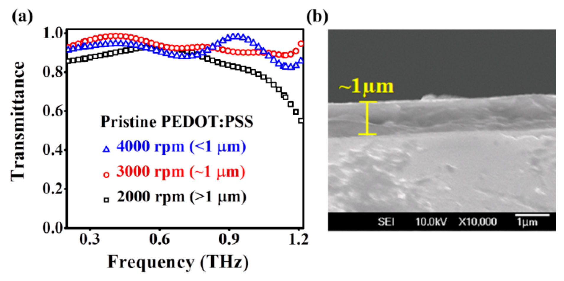
The frequency-dependent transmittance of pristine PEDOT: PSS layers with three different thicknesses in the THz frequency band are shown in
Figure 3a. It can be seen that the best THz transmittance is achieved for a pristine PEDOT: PSS layer spin-coated at a speed of 3000rpm, with a thickness of approximately 1 µm, confirmed by a cross-sectional image obtained by field emission scanning electron microscope (FESEM) (see
Figure 3b). This sample exhibited an average THz transmittance as high as 92% and a relative flat response across a wide frequency range of 0.2–1.2 THz. The FESEM cross-sectional images of films spin-coated at 2000 and 4000 rpm are similar to those shown in
Figure 3b.
The apparent fluctuation in THz transmittance for thinner (<1 µm) pristine PEDOT: PSS layers as shown in
Figure 3a is possibly caused by the scattering effect at the interface of the film and the substrate, especially at the higher THz frequency [
26]. Although we cannot provide a quantitative analysis on this conjecture, scattering could arise from a variation in the surface morphology of the thinner films. On the other hand, a pristine PEDOT: PSS layer with a thickness greater than 1 µm (>1 µm) showed a somewhat lower average transmittance of approximately 85% at the frequency range of 0.2–0.7 THz. The transmittance gradually decreased to less than 60% for f >0.7 THz. This is tentatively attributed to the slow-varying broad-band frequency-dependent absorption of the pristine PEDOT: PSS layer, which becomes significant for thicker films.
Based on the observations above, we chose the 1 µm thick pristine PEDOT: PSS layer for THz phase shifter applications as TCEs. We note that the present 1 µm thick pristine PEDOT: PSS layer exhibits a much higher THz transmittance as compared with published reports [
14,
15]. It is possible that different manufactured batches of pristine PEDOT could have subtle differences in the THz optical properties. Further analysis is needed to ascertain the observed phenomena. In addition, the THz transmittance achieved is much higher than those for DMSO- and EG-doped PEDOT: PSS thin layers, where their thicknesses are only approximately 31 and 34 nm, respectively [
14,
15].
In this study, we chose two LCs: MDA-00-3461 from Merck and Mixture 1825 proposed by Dąbrowski et al. [
27,
28]. The former is readily available and affordable. The latter exhibits birefringence almost twice as high as the former. As it is well known, LCs with high birefringence offer possibilities for greater tenability and more functionalities. However, other issues, such as transparency in the THz frequency range and dynamic responses, must be considered. Therefore, we constructed LC THz phase shifters using both types of LCs for a comparative study. Figures of merit for LC THz phase shifters, defined in a later section, were used to facilitate the selection of LCs for THz device applications. As we shall see, higher-birefringence LCs do not offer decisive advantages over LCs with somewhat lower ones.
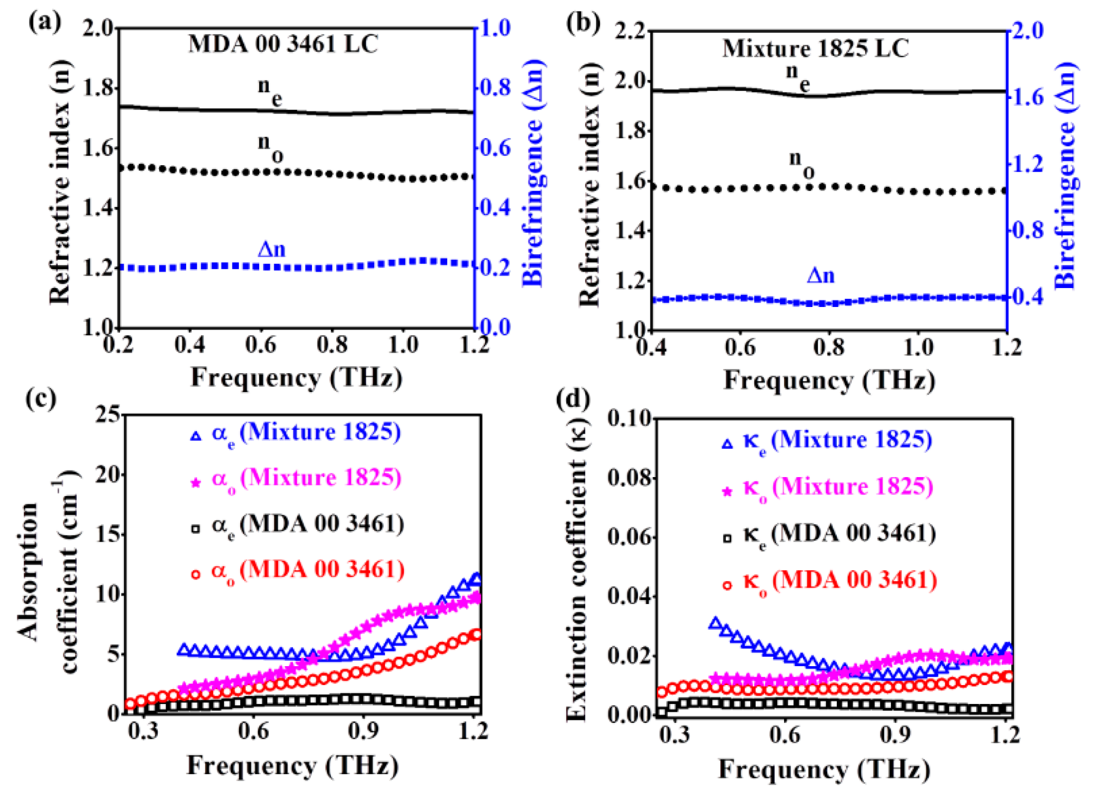
The THz optical constants
no,
ne, and Δ
n of MDA-00-3461 and Mixture 1825 LC are shown in
Figure 4a,b, respectively. We determined that the
no,
ne, and Δ
n for MDA-00-3461 LC were ~1.53, ~1.73, and ~0.2, respectively, and were relatively frequency-independent in the frequency range of 0.2–1.2 THz. Such results are in agreement with those obtained in our previous work (
no ~1.54,
ne ~1.74, and Δ
n ~0.2 in the frequency range of 0.3–1.4 THz) [
27]. Similarly, the values of the parameters for Mixture 1825 LC were found to be ~1.56, ~1.96, and ~0.4, respectively, in the frequency range of 0.4–1.2 THz. In this case, we achieved a slightly higher Δn of approximately 0.4 as compared with the reported value of 0.387 at 1 THz by Dąbrowski et al. [
28], which may be attributed to the different batch production and a more accurate analysis. The Δ
n values indicate that the thickness of the LC phase shifter could be reduced to a half with the use of Mixture 1825 instead of MDA-00-3461 to achieve the same phase shift.
The THz absorption coefficients for both ordinary (
αo) and extraordinary (
αe) rays for MDA-00-3461 and Mixture 1825 LC are shown in
Figure 4c. The coefficients
αo and
αe of MDA-00-3461 LC are estimated to be ~1 cm
−1 and ~6.6 cm
−1, respectively, at 1.2 THz. In contrast,
αo and
αe of Mixture 1825 LC are higher and estimated to be ~9.7 cm
−1 and ~11.2 cm
−1, respectively, at 1.2 THz. We also evaluated the THz frequency-dependent extinction coefficients (
κ) for ordinary (
κo) and extraordinary (
κe) rays of both LCs as shown in
Figure 4d. In comparison with MDA-00-3461, Mixture 1825 exhibits larger absorption or extinction coefficients and a slightly frequency-dependent nonlinear behavior.
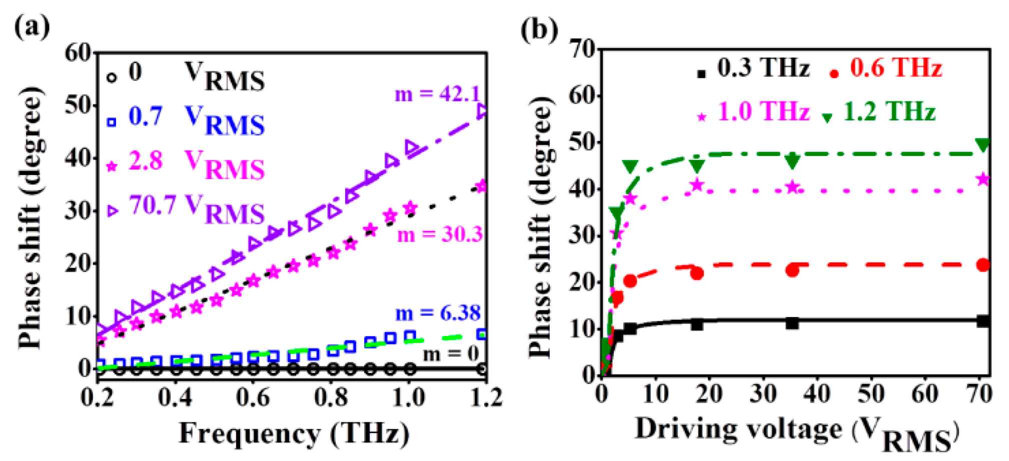
Our demonstration of an MDA-250 TN-LC phase shifter confirms the reliability of high-transmittance pristine PEDOT: PSS as TCEs. We plotted the phase shift as a function of frequency at four different voltages in
Figure 5a. The experimental data can be well fitted by linear lines. The slopes of these fitting curves gradually increase with increasing applied voltages. For the phase shifter based on MDA-250, the slope of the linear fitting curves varies from 6.38/THz to 42.1/THz as the applied voltage is ramped from 0.7 to 70.7 V
RMS. We plotted the phase shift as a function of applied voltage at four different THz frequencies in
Figure 5b. Theoretical curves according to Equation (1) are also shown. The results indicate that theoretical predications of phase shifts fit the experimental data well for applied voltages from 0 to 70 V
RMS. A phase shift of 45° at 1.2 THz can be achieved with a driving voltage (V
D) as low as 5.2 V
RMS. The threshold voltage (V
TN) determined from the experimental data is approximately 0.5 V
RMS.
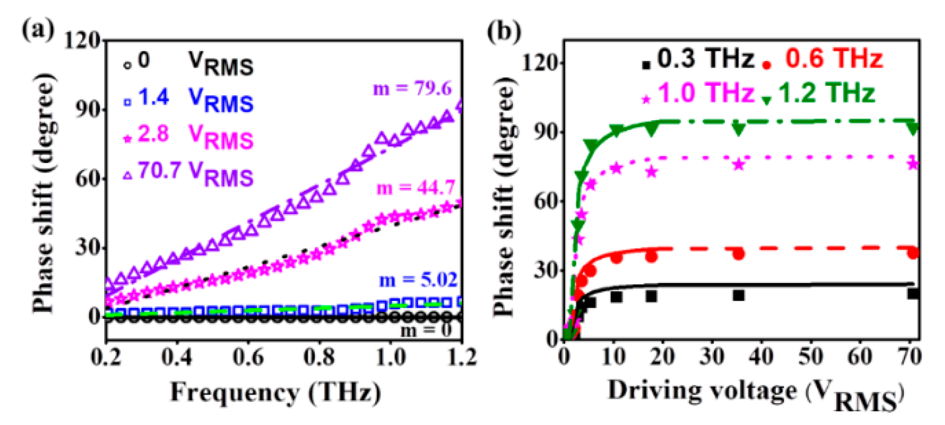
Next, we investigated MDA-550 TN-LC phase shifters in order to evaluate the performances of such devices to achieve a 90° phase shift at ~1.2 THz using pristine PEDOT: PSS as TCEs layers. The phase shift as a function of the THz frequency at four different voltages is shown in
Figure 6a. In addition, we present the phase shift as a function of the applied voltage at four different THz frequencies as shown in
Figure 6b. For the phase shifter based on MDA-550, the slope for linear fit varies from 5.02/THz to 79.6/THz as the applied voltage is ramped from 1.4 to 70.7 V
RMS. We can achieve a 90° phase shift at 1.2 THz with a V
D of approximately 7.9 V
RMS. The experimentally determined V
TN is 0.7 V
RMS. The slightly higher V
D and V
TN for the MDA-550 device in comparison with the MDA-250 TN-LC phase shifter is ascribed to the increase in misalignment of LC molecules and the decrease in the electric field strength with the increasing thickness of the cell.
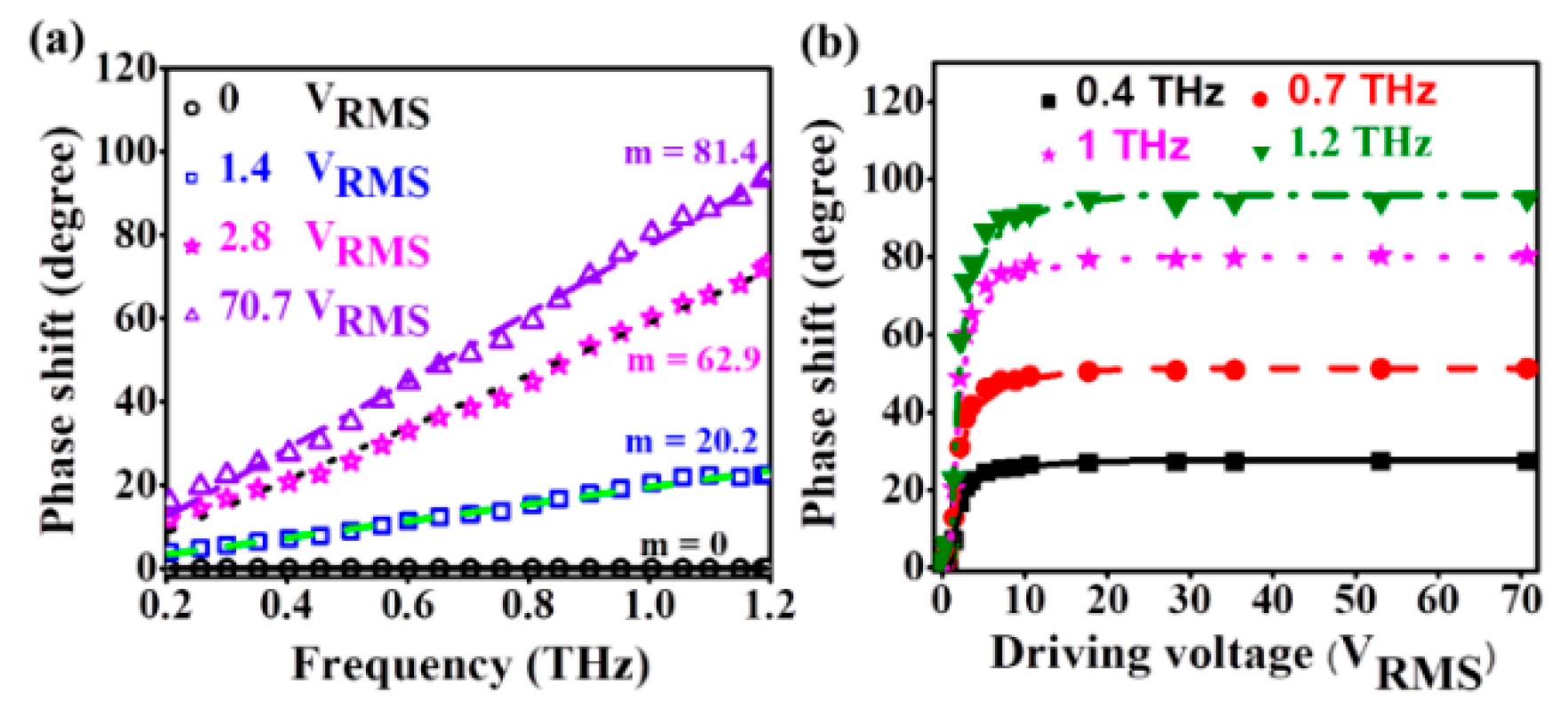
We also constructed a Mixture-250 TN-LC phase shifter with a 250 µm thickness of mixture 1825 LC layer. The phase shift achieved by the device at four different voltages are shown in
Figure 7a. The slope of linear fitting curves varies from 2.02/THz to 81.4/THz as the applied voltage is ramped from 1.4 to 70.7 V
RMS. The maximum slope achieved is approximately 81.4 at the applied voltage 70 V
RMS, which is much higher in comparison with those for the MDA-250 and MDA-550 TN-LC phase shifters. This is expected because of the high birefringence of Mixture 250. We also plotted the phase shift as a function of applied voltage at four different THz frequencies as shown in
Figure 7b. There occurred a phase shift greater than 90° at the frequency of 1.2 THz with a V
D of approximately 7 V
RMS. The experimentally determined V
TN of this phase shifter is 0.5 V
RMS. The experimental data also agree well with theoretical data that have been predicted. In addition, this work is the first to demonstrate TN-LC-based THz phase shifters using such LCs with higher birefringence. Previously, Du et al. [
11] demonstrated a phase shifter with DMSO-doped PEDOT, which exhibited higher conductivities than pristine PEDOT films. However, we found that the electrical conductivity of pristine PEDOT: PSS is suitable enough to operate 90° THz phase shifters.
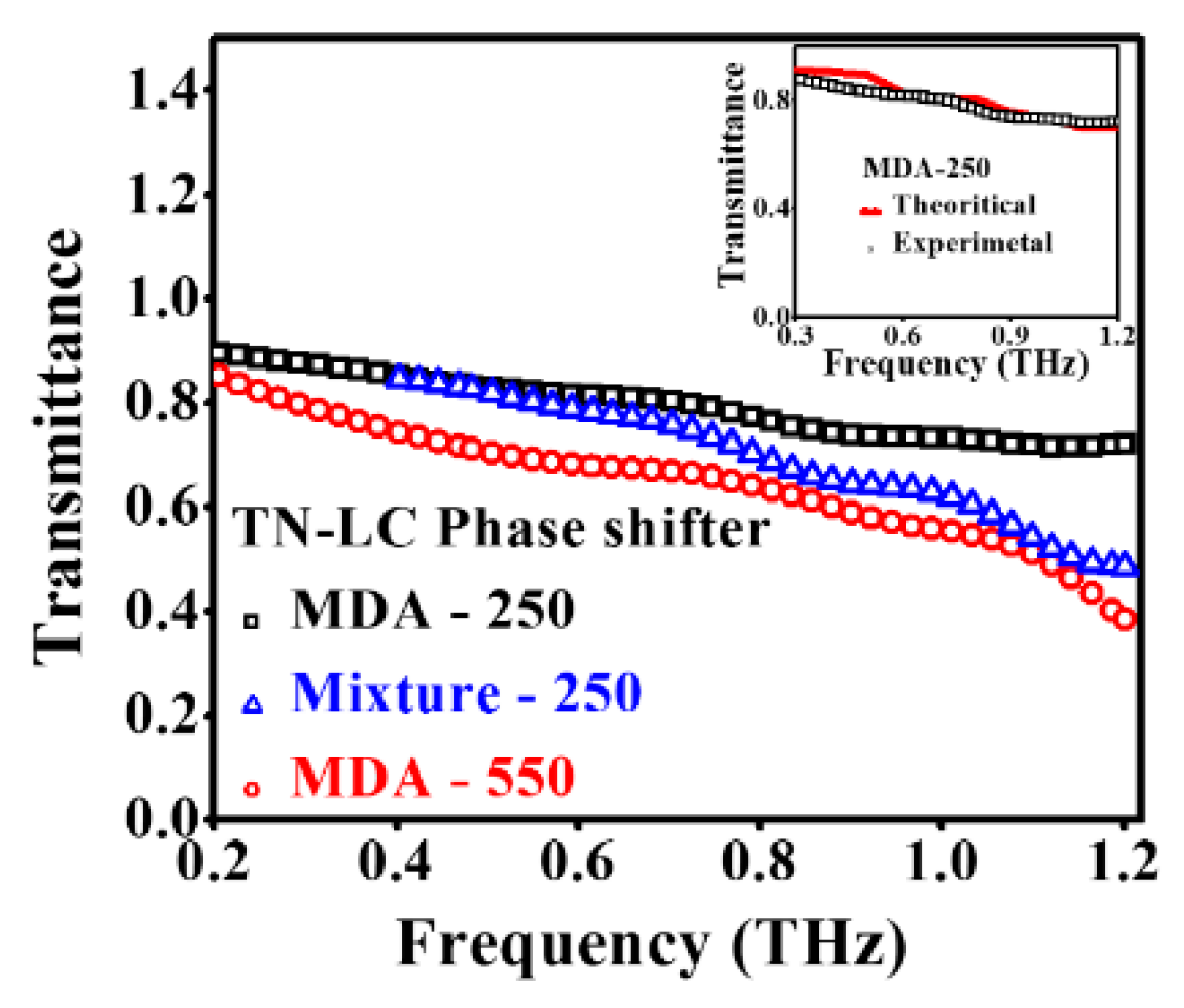
THz transmittance values of MDA-250, MDA-550, and Mixture-250 TN-LC phase shifters are shown in
Figure 8. The average THz transmittance of the MDA-250 device is as high as 80% at 0.2 THz and shows a decreasing trend with frequency, down to ~30% at 1.2 THz. The observed behavior can be explained by the frequency-dependence of absorption and the interface reflection of the components of the device, namely, LC, fused silica substrates, PEDOT: PSS, and polyimide alignment layers. The inset in
Figure 8 shows the theoretical transmittance curve for the MDA-250 device, which is in good agreement with the experimental data. The transmittance of MDA-550 and Mixture-250 devices show similar trends. The theoretically calculated transmittance values for MDA-550 and Mixture-250 TN-LC THz phase shifters are 64.5% and 62.8%, respectively, at 1 THz. This is very close to our experimental data of Mixture-250 devices at 1 THz (i.e., 62%). The theoretical and experimental transmittance of the MDA-250 device is superior, being ~73% at 1 THz. Overall, the loss experienced by our devices compares favorably with THz phase shifters previously reported [
8,
9,
10,
11]. Moreover, we can attribute the gradually decreased transmittance in the THz frequency range to the strong frequency-dependent transmittance of fused silica substrates. This has been described in our previous work [
8]. By considering the structure described in
Figure 1 and combining the complex permittivities (and refractive indices) of pristine PEDOT: PSS, fused silica, and liquid crystals, we can estimate the loss caused by different interfaces. The loss is mainly contributed by fused silica substrates and the LC itself [
8].
Previously, several THz phase shifters which incorporated electrodes based on graphene, ITO-NW, and metal/porous graphene combination have been demonstrated [
9,
11,
29]. Most of the works were carried out with a homogeneously aligned LC cell. The experimentally determined threshold voltages for LC THz phase shifters with monolayer graphene, bilayer graphene, and ITO-NW as TCEs were 1.3, 1.25 and 1.7 V
RMS, respectively. These are much higher than that of the present TN-LC phase shifter (approximately 0.5 V
RMS). In addition, most of the THz phase shifters reported have shown much higher THz transmittance loss, for example, the transmittance was in the range of 55 to 20% for devices with nanostructured TCEs at THz frequencies, even though low-absorption-type LCs such as E7 or MDA-00-3461 have been used. This indicates that TCE layers play a vital role in determining THz transmittance loss experienced by the phase shifters. Moreover, many of these TCEs have some disadvantages (e.g., requiring complex processing steps and/or costly fabrication processes). In contrast, PEDOT: PSS can be fabricated by a simple spin coating method, which can significantly reduce the processing time and cost. Previously, Du et al. [
11] demonstrated a homogeneously aligned LC-based THz phase shifter using DMSO-doped PEDOT: PSS as a TCE layer and achieved a 90° phase shift with a V
D of ~2.5 V
RMS. This is much lower than for our Mixture-250 TN-LC device (7 V
RMS). However, their proposed phase shifter exhibited a higher threshold voltage of approximately 1.4 V
RMS in comparison with that for our Mixture-250 TN-LC device (0.5 V
RMS). Additionally, the DMSO-doped PEDOT: PSS phase shifter exhibited transmittance loss of nearly 95%, substantially higher than those of devices reported in this work.
Note that there is a difference in frequency ranges for
Figure 3,
Figure 4,
Figure 5,
Figure 6,
Figure 7 and
Figure 8 for devices using the two LCs. This arises from the relatively high absorption of the Mixture 1825 liquid crystal at low THz frequencies. From 0.2 to 0.4 THz, the absorption of Mixture 1825 is very high. As a result, the signal-to-noise ratio of the THz spectroscopic data is not very good. Therefore, authors are not able to get a reliable value for the THz optical constants of Mixture 1825 and accurately evaluate phase shifting properties for devices using Mixture 1825 in this band.
For discussing the performance of all types of TN-LC phase shifters, particularly previously reported homogeneously aligned LC phase shifters, we introduce a figure of merit (FOM) defined by the following:
where ΔΦ
max is the maximum phase shift with corresponding driving voltage (V
D-FOM) and L
dB is the transmittance loss of the phase shifter without the bias voltage at 1 THz. The calculated values of the FOM for several devices are summarized in
Table 2.
The highest FOM value of approximately 6.65 degree·dB
−1·V
−1 is associated with the Mixture-250 TN-LC-based THz phase shifter. On the other hand, the FOM value of a homogeneously aligned LC phase shifter [
11] is approximately 2.19 degree·dB
−1·V
−1. This is simply because of the very low transmittance of approximately 3% at 1 THz, even though the driving voltage is as low as 2.7 V
RMS. In addition, it is much easier to form a micron-level thickness of PEDOT: PSS layer on a large area substrate using the spin coating method. The fabrication cost, complexity, and transmittance loss can be reduced by employing the pristine form of PEDOT: PSS as a TCE film in comparison with doping with either DMSO or EG.
Dynamic responses of the devices are also of interest. The voltage-on and voltage-off times were measured by subjecting the device to a step-function-like voltage signal. The 20% to 80% rise time and fall time for an MDA-550 TN-LC phase shifter were found to be around 23 s and 120 s, respectively. The response time of the voltage-off state depended only on the material properties and cell thickness. The device based on Mixture 1825 is potentially advantageous due to its much higher birefringence. Nonetheless, the viscosity of such LCs is higher, namely, 311 [
28] versus ~203 cP for MDA [
30]. Thus, possible improvements using this approach remain to be seen.
Because of the slow responses, the present device is not suitable for applications that require fast modulation. However, the device is appropriate for instrumentation or apparatuses that require, for example, tunable waveplates with fine tuning capabilities.

 ,
, 


