Virtual Prototyping: Computational Device Placements within Detailed Human Heart Models


1
Department of Surgery, University of Minnesota, Minneapolis, MN 55455, USA
2
Medtronic, Minneapolis, MN 55112, USA
*
Author to whom correspondence should be addressed.
Appl. Sci. 2020, 10(1), 175; https://doi.org/10.3390/app10010175
Submission received: 30 October 2019
/
Revised: 18 November 2019
/
Accepted: 1 December 2019
/
Published: 25 December 2019
(This article belongs to the Special Issue 3D Printing of Bioactive Medical Device)
Abstract
:Data relative to anatomical measurements, spatial relationships, and device–tissue interaction are invaluable to medical device designers. However, obtaining these datasets from a wide range of anatomical specimens can be difficult and time consuming, forcing designers to make decisions on the requisite shapes and sizes of a device from a restricted number of specimens. The Visible Heart® Laboratories have a unique library of over 500 perfusion-fixed human cardiac specimens from organ donors whose hearts (and or lungs) were not deemed viable for transplantation. These hearts encompass a wide variety of pathologies, patient demographics, surgical repairs, and/or interventional procedures. Further, these specimens are an important resource for anatomical study, and their utility may be augmented via generation of 3D computational anatomical models, i.e., from obtained post-fixation magnetic resonance imaging (MRI) scans. In order to optimize device designs and procedural developments, computer generated models of medical devices and delivery tools can be computationally positioned within any of the generated anatomical models. The resulting co-registered 3D models can be 3D printed and analyzed to better understand relative interfaces between a specific device and cardiac tissues within a large number of diverse cardiac specimens that would be otherwise unattainable.
1. Introduction
The process for developing novel medical devices, procedural delivery systems, and/or next generation devices can be long, arduous, and extremely costly. For example, many steps must be taken to ensure that the device will fit correctly within a specified patient population. Typically, animal and cadaver studies are conducted to assist in determining such parameters for a device to fit into the relative anatomies [1]. While these studies offer many benefits, they are costly and time-consuming, and anatomies can vary greatly from living patients. Thus, medical device innovators are seeking novel methodologies, such as computational modeling, to gain further insights into device designs [2,3]. This has initiated an increased use of computational modeling by medical device innovators to assist in the design, refinement, and/or validation of their devices [4].
Software packages from companies such as Materialise (Mimics and 3-Matic suites; Leuven, Belgium) have greatly aided in the creation (segmentation) of computational 3D models. Digital Imaging and Communications in Medicine (DICOM) files such as those obtained from computed tomography (CT) or magnetic resonance imaging (MRI) from cadaveric or clinical cases can be uploaded to these software packages for segmentation. Anatomical measurements can be abstracted from these 3D models, which is largely beneficial for improving the understanding of a wide variety of human anatomies. These measurements can also be utilized to quantify the statistical distributions of specific anatomical features within various patient populations [5,6].
In addition, medical device models can be computationally implanted into the anatomical models and subsequently 3D printed, thereby offering additional unique insights relative to the interactions between a given device and a patient’s specific anatomy. Performing these implants in several anatomical models demonstrates how these devices would likely fit within varied patient anatomies. In other words, the generated 3D printed models grant further knowledge about implant site anatomies, clinical procedures, and optimal device placements, further enabling refinement of the device design to better fit an initial target population before performing expensive and time-consuming cadaver and/or animal studies. These anatomy-device models are also useful for explaining novel medical technologies to physicians. The 3D printed models help facilitate discussions between physicians and device engineers. The function of the model can be educational (explaining how the device functions) or beneficial for gaining iterative device prototype feedback (demonstrating a prototype device computationally placed in a heart and receiving feedback from physicians on how to improve the next iteration of the device).
Additionally, 3D prints of computational device placements within anatomical models offer benefits outside of medical device design. These 3D printed models can be utilized by clinical care teams to better communicate the details of a surgical procedure or as intervention amongst themselves and/or with a patient or their family. For example, investigators seeking to quantify these benefits have found that 3D printed anatomical models significantly improved patient understanding of the planned procedure and relevant anatomy [7], thus bridging the gap of knowledge between clinical care teams and their patients.
Here we demonstrate the ability to computationally place devices within varied and detailed 3D human cardiac models. These devices were placed in a variety of locations within anatomical models, as a means to study the device–tissue interface at differing implant sites. Devices were also placed in a number of different computational models with varied anatomies, allowing for the determination of ideal device placement locations, as well as for the characterization of variances in anatomical delivery pathways. Finally, these models were sliced to yield views of specific internal anatomies that would not be possible on the original specimen without destroying it.
2. Materials and Methods
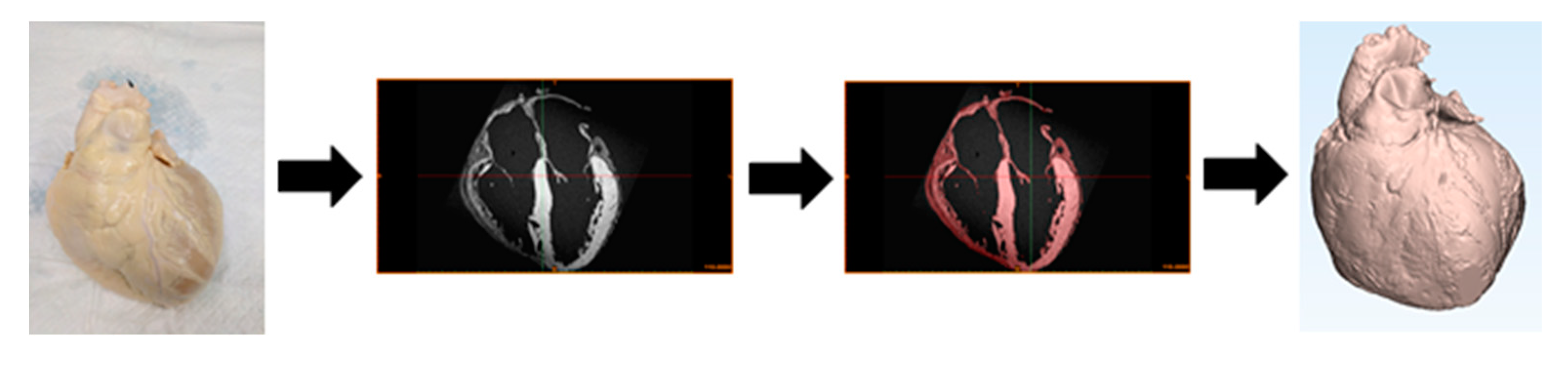
Human hearts deemed not viable for transplant were gifted to the Visible Heart® Laboratories for research through LifeSource, a regional organ procurement agency (St. Paul, Minnesota, MN, USA). Occasionally, these cardiac specimens were reanimated on an external perfusion apparatus utilizing Visible Heart® methodologies, allowing for capture of functional internal anatomy videos [8]. These isolated cardiac samples were perfusion fixed in an end-diastolic state and subsequently placed in agar gel, then MRI scanned utilizing a 3T MRI scanner at a resolution of 100 micrometers (Siemens Trio, Washington, DC, USA). Utilizing MRI scans of perfusion-fixed samples allows us to achieve high anatomic resolution, which is critical to perform virtual prototyping. Note that this is 10× greater resolution than can be obtained with clinical imaging, since the patient heart is living and moving. The DICOM generated from these scans was segmented utilizing Mimics software (version 20.0; Materialise). The process of segmentation involved creating 2D masks by classifying pixels as to whether they represent cardiac tissue on each scan slice. The 2D masks were compiled within Mimics to create a 3D anatomical model of the cardiac specimen. The model was then imported into 3-Matic software (version 14.0; Materialise) for processing, editing, and analysis of the 3D anatomical mesh (Figure 1).
To date, the Visible Heart® Laboratories have generated over 100 detailed 3D models of human cardiac anatomies, including a wide range of pathologies. These models can be utilized to gain critical insights into complex cardiac anatomies and alteration associated with disease states. Models of medical device prototypes can be computationally implanted in these anatomical models, allowing for analysis of device–tissue interactions and unique understanding of spatial relationships. The 3D models can offer distinctive views of specific internal anatomies and computationally placed devices.
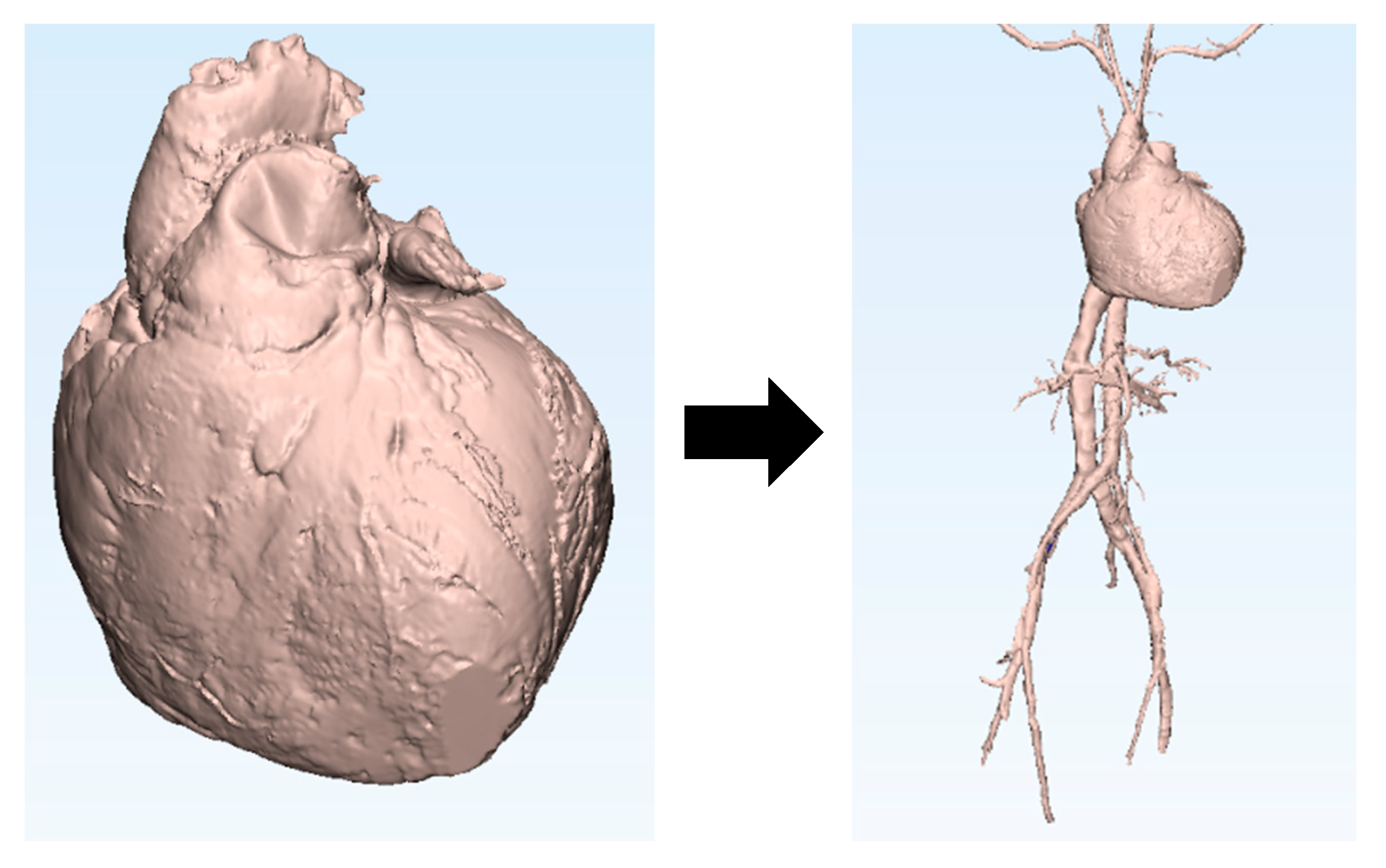
The Visible Heart® Laboratories have also generated 3D models of peripheral vasculatures (Figure 2). These datasets were obtained by scanning fresh cadavers that were donated through the Anatomy Bequest Program at the University of Minnesota. Large volumes of contrast dye (>2 L) were injected through the venous and arterial systems before or while obtaining CT scans. To date, 3D models of the major vasculatures between the subclavian veins and arteries down to the femoral veins and arteries have been generated from multiple cadaver scans. These vasculature models can be computationally added to previously generated heart models to simulate possible delivery pathways for a variety of cardiac devices, e.g., those commonly delivered through the femoral and subclavian veins or arteries.
Finally, these models can be 3D printed utilizing either Stratasys (Rehovot, Israel) GrabCAD Print version 1.30 software and uPrint SE Plus 3D printers, or Ultimaker (Utrecht, The Netherlands) Cura 4.1.0 software and Ultimaker 3E 3D printers. Numerous models were printed utilizing polylactic acid (PLA) filament for the model material and polyvinyl alcohol (PVA) filament for the support material. These 3D printed models clearly depict three-dimensional spatial information between various patient anatomies and computationally placed devices, thus enabling further quantitative analysis of computationally implanted devices within a wide range of anatomies.
3. Results and Discussion
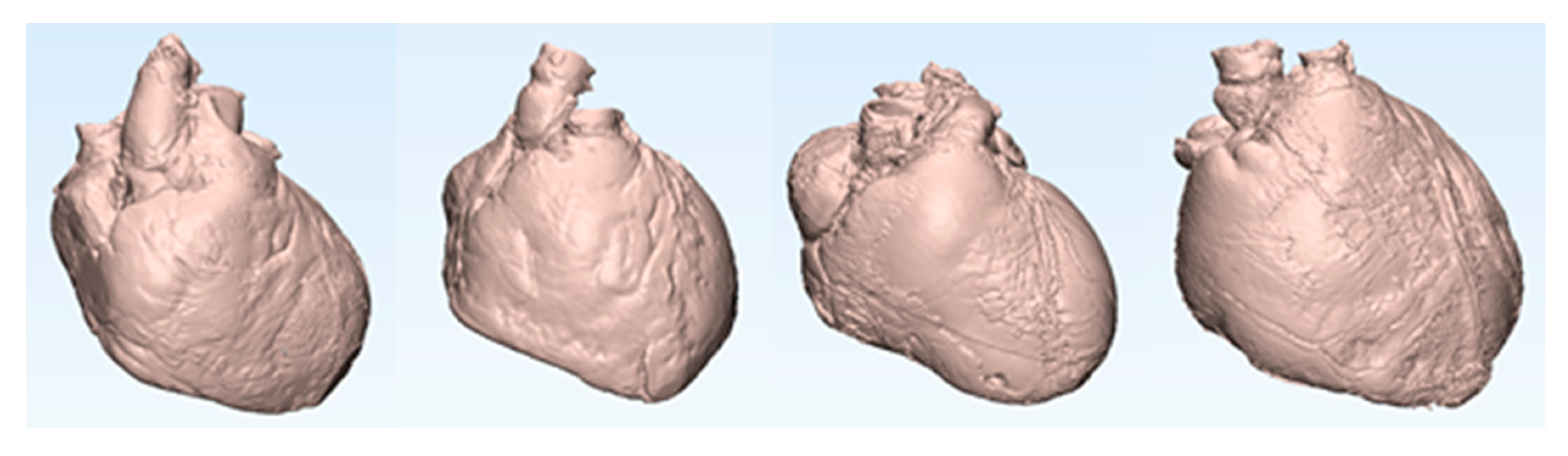
Here we describe a set of 3D models generated from four distinct human hearts utilizing the aforementioned methodology. Relevant information about each patient is summarized in Table 1. These models are displayed in attitudinally correct anatomical orientation in Figure 3. A MicraTM transcatheter pacing system (TPS) (Medtronic, Minneapolis, MN, USA) was computationally implanted into the right ventricular apex of each patient’s heart model. Each heart model was then sliced along the coronal plane to offer a clear view of the anterior half of the heart and the resultant computational implant locations of these MicraTM devices.
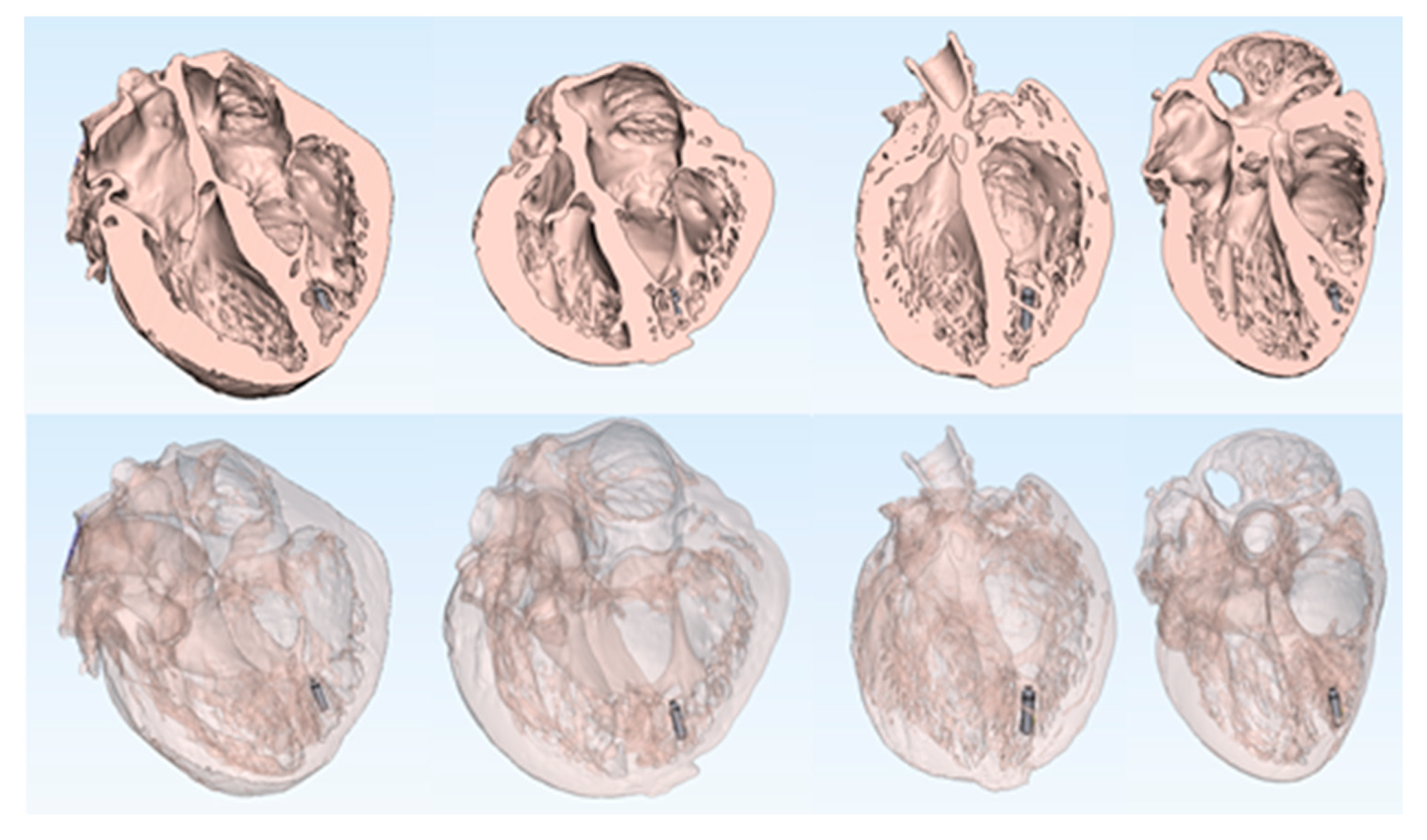
Further, implanting this device in a variety of models allows for the characterization of device placement within varied human anatomy (Figure 4). Since the MicraTM TPS has only one size, it was originally imperative to understand how the device fit within a range of human heart sizes.
Computational vasculature anatomies obtained from a cadaver CT scan were digitally added to the heart (Figure 5). This can then be utilized to model the delivery pathways, e.g., from implant into the vasculature upward from femoral veins and/or arteries up to the modeled heart. Further, we have been able to computationally add the delivery catheter for the MicraTM TPS into the modeled vascular pathway. In other words, we computationally modeled the MicraTM TPS implant along the entire delivery vascular pathway of the device, from the access point into the femoral vein, up through the inferior vena cava, right atrium, and finally into the right ventricular apex. This model, and other similar models, allow device designers to understand the anatomical constraints that affect the delivery of the MicraTM TPS to an ideal target location—a crucial step due to this large bore delivery catheter (23 French). Such insights should further enable design requirements to be established for a delivery catheter system, even before expensive animal and cadaver experiments are initiated. Additionally, these computational models can be used to help determine the constraints or boundary conditions of given anatomical sites, e.g., those that a catheter will be able to navigate and deploy a MicraTM TPS within, for patients with similar anatomy.
Shown in Figure 6, this model was digitally sliced along the coronal plane to reveal the posterior half of the heart and the computationally placed MicraTM TPS and delivery catheter. This model was then 3D printed and hand painted to highlight the different anatomical features as well the implant system and MicraTM TPS (the implanted device). This printed and painted model offers a realistic representation of a device implanted in a human patient, and its interaction with the surrounding anatomical features.
During early MicraTM TPS development and physician feedback sessions, it was questioned if more than one MicraTM TPS could be implanted within a patient’s heart (e.g., for end of device life replacement). Thus, designers needed to understand that the large volume of the right ventricle would allow for the placement of non-interacting concomitant MicraTM TPS within the same chamber. Fresh human cadaveric studies were performed on a small set of human hearts [9]. In Figure 7, we can visualize that a second MicraTM TPS was computationally deployed within this detailed cardiac anatomy, to simulate the spatial conditions where multiple MicraTM TPS were implanted within a patient’s right ventricle. The heart model was sliced along the coronal plane to reveal a four-chamber view of the posterior half of the heart. The model was then 3D printed for further analyses and educational use (Figure 7).
In another example of the value of computationally placed cardiac devices within these detailed human heart models, a Medtronic Arctic Front cryoballoon catheter was computationally placed within a human heart model (Figure 8). This human heart model had vasculature from a cadaver computationally added to simulate the delivery pathway required to navigate the cryoballoon from the access point within the femoral vein, proximally up to the left superior pulmonary vein ostia within the left atrium. This ablation balloon placement procedure requires an initial atrial transseptal puncture, which here was computationally placed into an anatomically accurate location on the atrial septal wall of the human heart model. The resulting computational model was 3D printed and has been utilized as an educational tool to explain the necessary steps of this complex procedure to medical students, residents, fellows, clinicians, patients, and/or medical device designers.
4. Conclusions
3D printing and computational modeling are emerging tools within both clinical and medical device innovation fields, as they have incredible potential to assist and change the way medical devices are designed and/or clinically adopted and utilized. These computational modeling and printing applications offer many benefits when compared to traditional methods of testing devices such as within human cadaver and/or animal studies. We consider that computational approaches are complementary to established preclinical and clinical device and procedure testing. The large cardiac and cadaver model database of the Visible Heart® Laboratories is an invaluable resource for such computational cardiac device placements, due to the large number and great diversity of detailed anatomical models in its human heart library. The generation of 3D printed models of these computational device placements enables further analysis and education of the procedures, device–tissue interfaces, and complex human anatomies.
Author Contributions
Conceptualization, P.A.I.; Methodology, P.A.I.; Software, A.J.D. and A.R.M.; Validation, A.J.D., A.R.M. and T.L.I.; Formal Analysis, A.J.D. and A.R.M.; Investigation, A.J.D. and A.R.M.; Resources, T.L.I.; Data Curation, A.J.D., A.R.M. and T.L.I.; Writing—Original Draft Preparation, A.J.D.; Writing—Review & Editing, P.A.I., A.R.M., and T.L.I.; Visualization, A.J.D.; Supervision, P.A.I. and T.L.I.; Project Administration, P.A.I. and T.L.I.; Funding Acquisition, P.A.I. All authors have read and agreed to the published version of the manuscript.
Funding
This research was funded by the Institute of Engineering in Medicine at the University of Minnesota and a research contract with Medtronic. 3D printing material was gifted to the lab by Stratasys. Sponsors had no role in the design of the study; in the collection, analyses, or interpretation of data; in the writing of the manuscript, and in the decision to publish the results.
Conflicts of Interest
The authors declare no conflict of interest.
References
- Holm, M.S.; Iaizzo, P.A. Importance of Human Cadaver Studies in Education and Medical Device Research: Insights Derived from Various Imaging Studies and Modalities. In Engineering in Medicine: Advances and Challenges; Iaizzo, P.A., Ed.; Academic Press: Cambridge, MA, USA, 2019; pp. 255–280. ISBN 9780128135143. [Google Scholar]
- Zarins, C.K.; Taylor, C.A. Endovascular Device Design in the Future: Transformation from Trial and Error to Computational Design. J. Endovasc. Ther. 2009, 16, 12–21. [Google Scholar] [CrossRef] [PubMed]
- Goff, R.P.; Spencer, J.H.; Iaizzo, P.I. MRI Reconstructions of Human Phrenic Nerve Anatomy and Computational Modeling of Cryoballoon Ablative Therapy. Ann. Biomed. Eng. 2016, 44, 1097–1106. [Google Scholar] [CrossRef] [PubMed] [Green Version]
- Morrison, T.M.; Pathmanathan, P.; Adwan, M.; Margerrison, E. Advancing Regulatory Science with Computational Modeling for Medical Devices at the FDA’s Office of Science and Engineering Laboratories. Front. Med. 2018, 5, 241. [Google Scholar] [CrossRef] [PubMed] [Green Version]
- Spencer, J.H.; Goff, R.P.; Iaizzo, P.A. Left Phrenic Nerve Anatomy Relative to the Coronary Venous System: Implications for Phrenic Nerve Stimulation during Cardiac Resynchronization Therapy. Clin. Anat. 2015, 28, 621–626. [Google Scholar] [CrossRef] [PubMed]
- Warriner, R.K.; Haddad, M.; Hendry, P.J.; Mussivand, T. Virtual Anatomical Three-Dimensional Fit Trial for Intra-Thoracically Implanted Medical Devices. ASAIO J. 2004, 50, 354–359. [Google Scholar] [CrossRef] [PubMed]
- Bernhard, J.C.; Isotani, S.; Matsugasumi, T.; Duddalwar, V.; Hung, A.J.; Suer, E.; Baco, E.; Satkunasivam, R.; Djaladat, H.; Metcalfe, C.; et al. Personalized 3D Printed Model of Kidney and Tumor Anatomy: A Useful Tool for Patient Education. World J. Urol. 2016, 34, 337. [Google Scholar] [CrossRef] [PubMed]
- Chinchoy, E.; Soule, C.L.; Houlton, A.J.; Gallagher, W.J.; Hjelle, M.A.; Laske, T.G.; Morissette, J.; Iaizzo, P.A. Isolated Four-chamber Working Swine Heart Model. Ann. Thorac. Surg. 2000, 70, 70–1607. [Google Scholar] [CrossRef]
- Omdahl, P.; Eggen, M.D.; Bonner, M.D.; Iaizzo, P.A.; Wika, K. Right Ventricular Anatomy Can Accommodate Multiple Micra Transcatheter Pacemakers. Pacing Clin. Electrophysiol. 2016, 39, 393–397. [Google Scholar] [CrossRef] [PubMed] [Green Version]
Figure 1.
(Left to right) 3D model generation pipeline starting with profusion-fixed human heart, cardiac MRI scan, 2D segmentation mask of the cardiac myocardium, and resulting 3D model of the heart.
Figure 1.
(Left to right) 3D model generation pipeline starting with profusion-fixed human heart, cardiac MRI scan, 2D segmentation mask of the cardiac myocardium, and resulting 3D model of the heart.

Figure 2.
Example of a human heart model with computationally added vasculature.

Figure 3.
Computational 3D models of four MRI scanned human hearts from the Visible Heart® Laboratories (left to right: HH229, HH248, HH102, and HH311). These models were used for subsequent computational implants of cardiac devices.
Figure 3.
Computational 3D models of four MRI scanned human hearts from the Visible Heart® Laboratories (left to right: HH229, HH248, HH102, and HH311). These models were used for subsequent computational implants of cardiac devices.

Figure 4.
Anterior views of sliced human hearts depicting MicraTM transcatheter pacing system computationally implanted into each right ventricle (left to right: HH229, HH248, HH102, and HH311). Each heart model is depicted with no transparency (top) and high transparency (bottom).
Figure 4.
Anterior views of sliced human hearts depicting MicraTM transcatheter pacing system computationally implanted into each right ventricle (left to right: HH229, HH248, HH102, and HH311). Each heart model is depicted with no transparency (top) and high transparency (bottom).

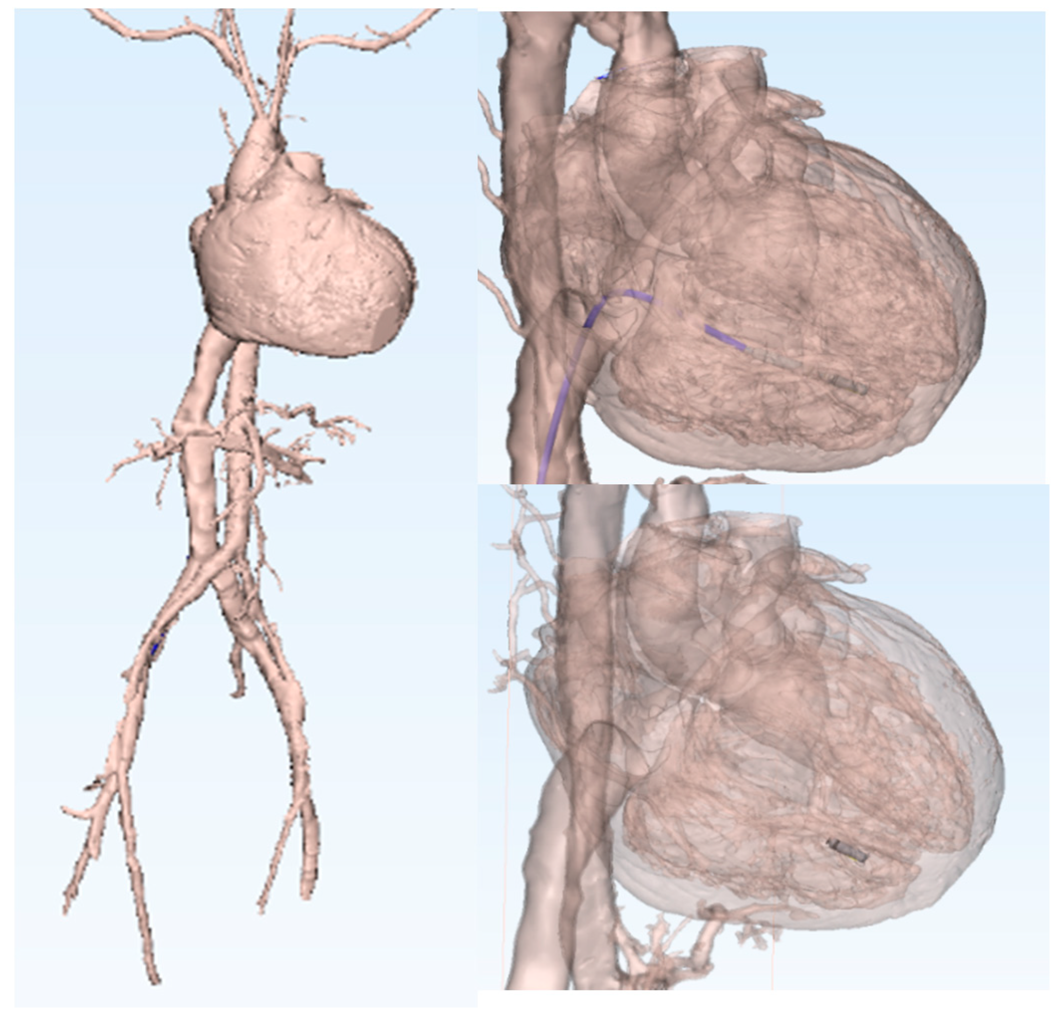
Figure 5.
3D human heart model (HH229) with computationally added vasculature. A MicraTM transcatheter pacing system delivery catheter and a MicraTM were computationally implanted in the right ventricular apex.
Figure 5.
3D human heart model (HH229) with computationally added vasculature. A MicraTM transcatheter pacing system delivery catheter and a MicraTM were computationally implanted in the right ventricular apex.

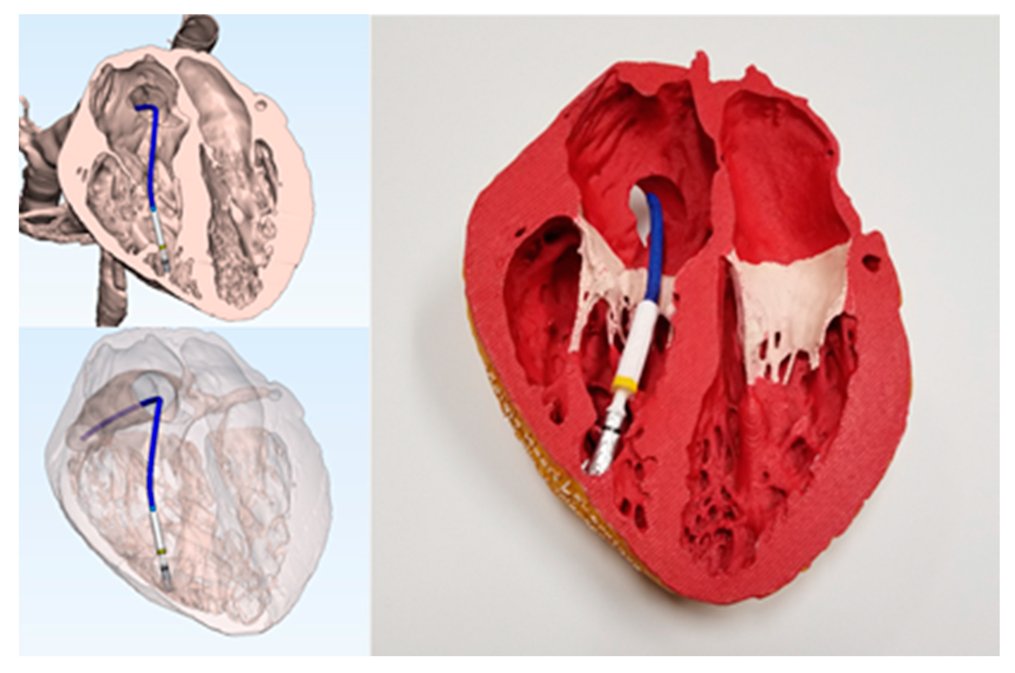
Figure 6.
3D models and 3D print of the posterior half of a human heart (HH229) with a computationally placed MicraTM transcatheter pacing system (TPS) and delivery catheter. The printed heart and MicraTM TPS were hand painted to highlight device–tissue interfaces.
Figure 6.
3D models and 3D print of the posterior half of a human heart (HH229) with a computationally placed MicraTM transcatheter pacing system (TPS) and delivery catheter. The printed heart and MicraTM TPS were hand painted to highlight device–tissue interfaces.

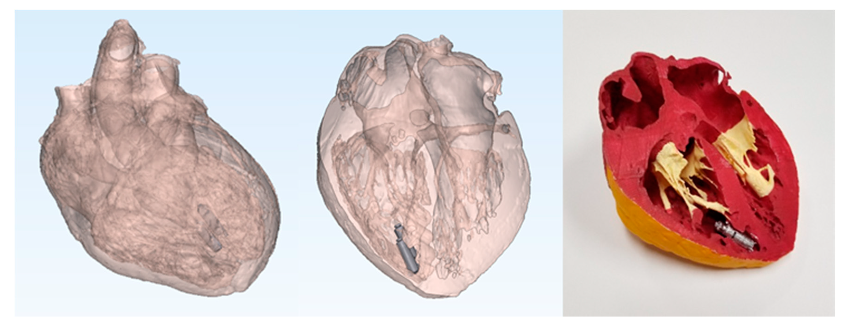
Figure 7.
Multiple MicraTM transcatheter pacing systems computationally implanted in the right ventricular apex of a 3D human heart model (HH229; left) and resulting 3D print that was hand painted to study device–issue interfaces (right).
Figure 7.
Multiple MicraTM transcatheter pacing systems computationally implanted in the right ventricular apex of a 3D human heart model (HH229; left) and resulting 3D print that was hand painted to study device–issue interfaces (right).

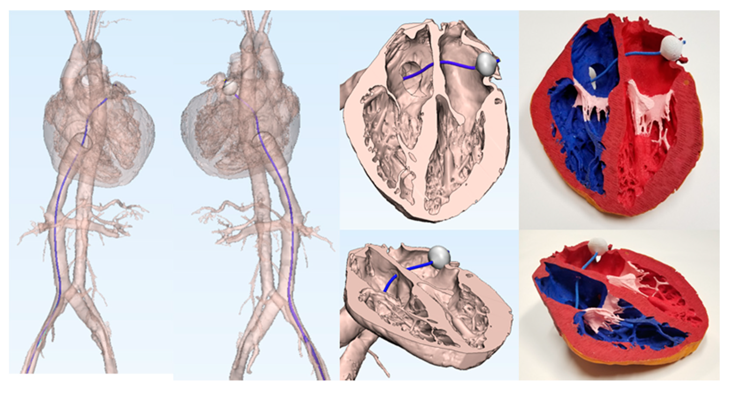
Figure 8.
Human heart (HH229) and vasculature model simulating the delivery pathway for a computationally placed Arctic Front catheter and cryoballoon in the left superior pulmonary vein ostia.
Figure 8.
Human heart (HH229) and vasculature model simulating the delivery pathway for a computationally placed Arctic Front catheter and cryoballoon in the left superior pulmonary vein ostia.


Table 1.
Human heart and patient information.
| Heart Number | Age | Gender | Body Weight (kg) | Body Height (cm) | Heart Weight (g) | Cardiac Medical History |
|---|---|---|---|---|---|---|
| 102 | 14 | F | 79.8 | 142 | 333.1 | None known |
| 229 | 44 | F | 83.8 | 163 | 394 | Hypertension |
| 248 | 64 | F | 105.6 | 178 | 441.4 | Hypertension |
| 311 | 20 | F | 38.6 | 142 | 161 | None known |
© 2019 by the authors. Licensee MDPI, Basel, Switzerland. This article is an open access article distributed under the terms and conditions of the Creative Commons Attribution (CC BY) license (http://creativecommons.org/licenses/by/4.0/).
Share and Cite
MDPI and ACS Style
Deakyne, A.J.; Iles, T.L.; Mattson, A.R.; Iaizzo, P.A. Virtual Prototyping: Computational Device Placements within Detailed Human Heart Models. Appl. Sci. 2020, 10, 175. https://doi.org/10.3390/app10010175
AMA Style
Deakyne AJ, Iles TL, Mattson AR, Iaizzo PA. Virtual Prototyping: Computational Device Placements within Detailed Human Heart Models. Applied Sciences. 2020; 10(1):175. https://doi.org/10.3390/app10010175
Chicago/Turabian StyleDeakyne, Alex J., Tinen L. Iles, Alexander R. Mattson, and Paul A. Iaizzo. 2020. "Virtual Prototyping: Computational Device Placements within Detailed Human Heart Models" Applied Sciences 10, no. 1: 175. https://doi.org/10.3390/app10010175
Note that from the first issue of 2016, this journal uses article numbers instead of page numbers. See further details here.