Design of Soft Origami Mechanisms with Targeted Symmetries
by
 ,
,
Andrew Gillman
1,2 ,
,
Gregory Wilson
3,
Kazuko Fuchi
4,5,
Darren Hartl
3,
Alexander Pankonien
5 and
Philip Buskohl
2,* 1
UES, Inc., Dayton, OH 45432, USA
2
Materials and Manufacturing Directorate, Air Force Research Laboratory, Wright-Patterson Air Force Base, OH 45433, USA
3
Department of Aerospace Engineering, Texas A&M University, College Station, TX 77843, USA
4
University of Dayton Research Institute, Dayton, OH 45469, USA
5
Aerospace Systems Directorate, Air Force Research Laboratory, Wright-Patterson Air Force Base, OH 45433, USA
*
Author to whom correspondence should be addressed.
Actuators 2019, 8(1), 3; https://doi.org/10.3390/act8010003
Submission received: 16 November 2018
/
Revised: 19 December 2018
/
Accepted: 20 December 2018
/
Published: 24 December 2018
(This article belongs to the Special Issue New Materials and Designs for Soft Actuators)
Abstract
:The integration of soft actuating materials within origami-based mechanisms is a novel method to amplify the actuated motion and tune the compliance of systems for low stiffness applications. Origami structures provide natural flexibility given the extreme geometric difference between thickness and length, and the energetically preferred bending deformation mode can naturally be used as a form of actuation. However, origami fold patterns that are designed for specific actuation motions and mechanical loading scenarios are needed to expand the library of fold-based actuation strategies. In this study, a recently developed optimization framework for maximizing the performance of compliant origami mechanisms is utilized to discover optimal actuating fold patterns. Variant patterns are discovered through exploring different symmetries in the input and output conditions of the optimization problem. Patterns designed for twist (rotational symmetry) yield significantly better performance, in terms of both geometric advantage and energy requirements, than patterns exhibiting vertical reflection symmetries. The mechanical energy requirements for each design are analyzed and compared for both the small and large applied displacement regimes. Utilizing the patterns discovered through optimization, the multistability of the actuating arms is demonstrated empirically with a paper prototype, where the stable configurations are accessed through local vertex pop-through instabilities. Lastly, the coupled mechanics of fold networks in these actuators yield useful macroscopic motions and can achieve stable shape change through accessing the local vertex instabilities. This survey of origami mechanisms, energy comparison, and multistability characterization provides a new set of designs for future integration with soft actuating materials.
1. Introduction
Soft actuating materials and mechanisms are key to the broad adoption of soft robotics, haptics, and man–machine interface concepts. Recent research has demonstrated significant gains in the actuation strain [1], cyclic frequency [2], and specific work [3], providing an array of soft actuating materials for use in specific applications [4,5]. The potential of these materials is compounded through the design of novel kinematic mechanisms and actuator placement schemes, which amplify the motion and transform a simple linear actuation into a complex 3D motion. Origami, the art of paper folding, has provided a rich source of fold-based mechanisms that demonstrate the impact of coupling actuating materials with structural reconfiguration for robotics systems [6]. For example, the spherical waterbomb pattern was combined with a coiled shape memory alloy to produce a variable radius soft robotic wheel [7,8]. Origami patterns have also been used to embed mechanologic properties in humidity-responsive films, highlighting how shape change and mechanical compliance can provide more than just locomotive properties [9]. Acoustic metamaterials [10], tunable anisotropy [11], and actuators with mechanical bandgaps [12] are further examples of the capability origami concepts can bring to soft robotics design and performance challenges.
By definition, origami mechanisms reduce 3D shape change into a series of folding operations. Although the fold topology and sequencing of the origami structure can remain complex, the actuation of an individual fold is relatively straightforward and has been exploited by several active material integration strategies [6,13]. Shape memory polymers (SMP) have been demonstrated as an effective single-use fold actuator for robotic deployment [14]. Folding motions have also been demonstrated in reprogrammable SMP systems based on shifting of the polymer glass transition temperature through local protonation/de-protonation of the polymer film [15]. Reversible actuating materials, such as shape memory alloys [7,16] and liquid crystal elastomers [17,18], have also been utilized for self-folding. Hydrogel-based self-folding materials have extended origami utility into the ultrasoft regimes, as demonstrated by photo-crosslinkable hydrogel hinges with programmable swelling [19]. Self-folding has even been applied to the ultrasmall regime through the fabrication of graphene-based folds for microscopic self-assembly and robotic applications [20].
The breadth of actuating materials and self-folding integration schemes motivates the development of design tools to identify optimal fold topologies for specific functionalities. Several design tools are available for geometry-based performance criteria, such as mapping to a target 3D shape or conforming to a target surface [21,22,23]. Rigid origami design rules have been applied to mechanism design [24], including the development of a kinematic origami classification guide [25]. Rigid approaches have also been extended to accommodate the finite thickness of panels [26], and origami manufacturing design tools, such as PopUP CAD [27], help streamline the process from design to fabricated prototype. However, for many applications, including soft robotics, the role of mechanics and material compliance are important metrics for consideration when designing the fold topology. Several mechanical representations have been developed, including truss [28,29,30] and frame [31] finite element (FE) models, and shell element analysis for optimization of shape memory alloy wire networks for self-folding [16,32]. Leveraging the efficiency of the truss model, we have developed a topology optimization tool that predicts an optimal origami pattern through selectively tuning the fold stiffness of a reference grid of fold lines, developed initially for a linear truss model [33] followed by our recent work incorporating our nonlinear formulation [34]. With the mechanics embedded within the design process, stiffness, applied loads, and energy distributions are all accessible design criteria for optimization. While these initial studies focused on the formulation and algorithmic challenges of a topology optimization framework, we utilize this capability here to identify origami mechanisms with different boundary condition symmetry groups, characterize the actuator compliance, and rank their energetic efficiency. Mechanical analysis is important for soft actuator design, as the loads required to deform the structure will inform the choice of active material to operate the fold.
Origami mechanisms can also possess multiple stable configurations, due to the complex trade-off of facet (stretching/bending) and folding energies. Waitukaitis et al. demonstrated the richness of the multistability landscape in origami by exhaustively searching for stable points in a 4-fold, single vertex pattern, which could possess up to six stable configurations depending on symmetry conditions [35]. Each vertex of the Miura-ori fold pattern exhibits a bistability, characterized by a local “pop-thru” defect which can regulate the global properties of the tessellation [11]. In addition, the waterbomb [30,36] and hypar [37,38] fold patterns also exhibit bistable behavior. Switching between bistable states could be leveraged for sensing and locomotion in soft robotic systems. For this purpose, the occurrence of bistabilities in the optimized mechanism designs will also be investigated.
The design of compliant origami mechanisms for use in soft material systems is investigated in this study. Building on previous work, we utilize a nonlinear truss FE model within a gradient-based topology optimization tool to predict optimal fold patterns under a series of mechanical boundary conditions. The boundary conditions are based on vertical reflection and rotational point symmetries of the reference grid. The topologies are optimized in the small displacement regime and further studied in the large displacement regime. Gradient methods are utilized in this work for systematic study of problem setup symmetries. The mechanical energy of the actuating designs are compared in both the small and large displacement regimes, which is a useful metric for active material selection and overall energy budget considerations for a robotic system. Lastly, the stability of the designs predicted in this study are empirically investigated using paper models. By targeting specific symmetries, the modularity of origami topologies can be leveraged to create larger networks. Here, networks of the discovered origami topologies are then assembled to demonstrate how coordinated activation of the stable states can yield large reconfigurations.
2. Optimization Framework for Nonlinear Origami Mechanics
This work utilizes a recently developed topology optimization approach for discovering origami fold patterns that result in optimal out of plane motion. Evaluation of the objective function leverages a nonlinear truss-based finite element model for accurately and efficiently modeling the origami actuator motions, which exhibit highly geometric nonlinear motions.
2.1. Optimization Overview
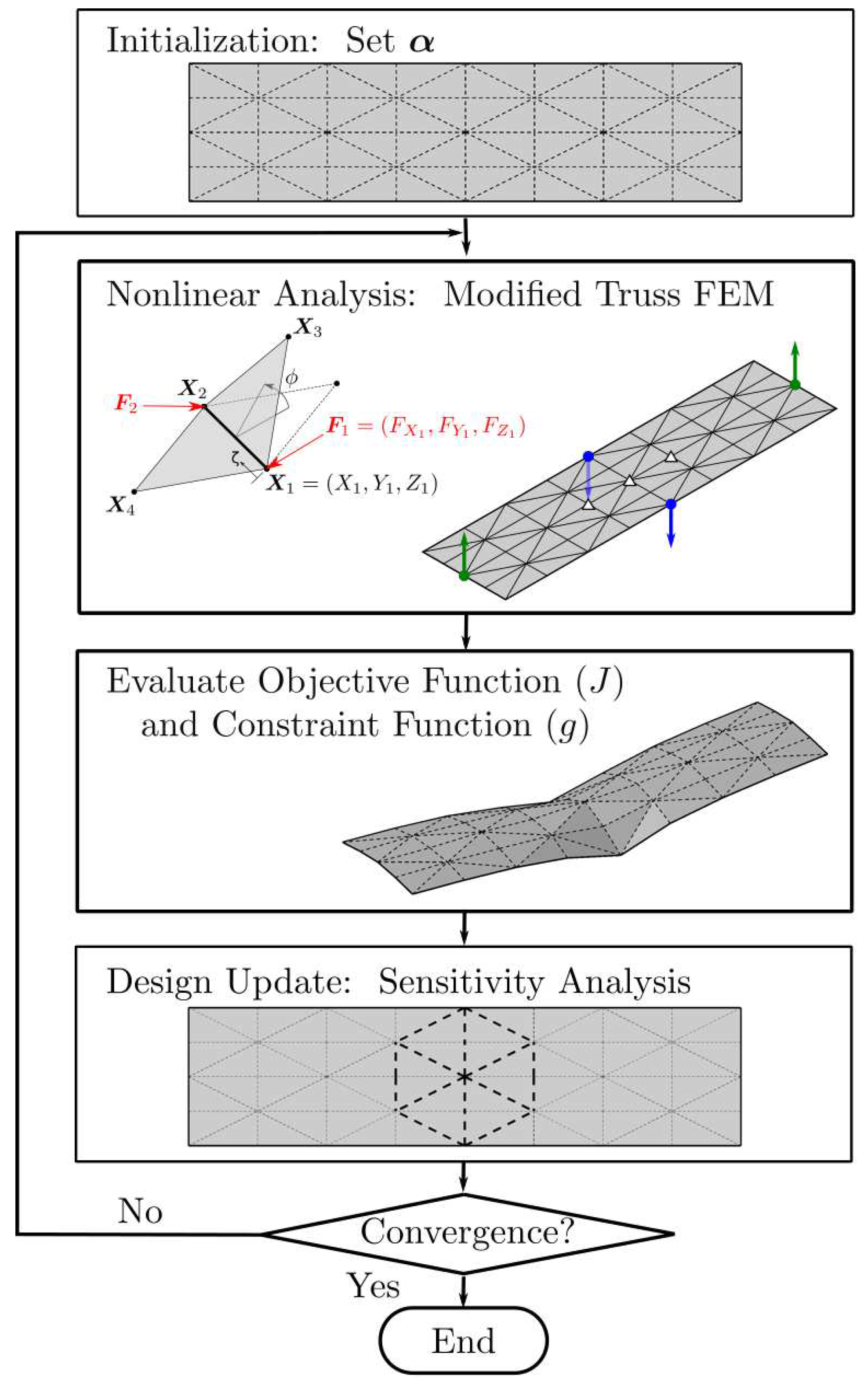
An overview of the topology optimization framework is presented in Figure 1. Details of this framework have been described in our prior work including implementations incorporating both linear [33,39] and nonlinear [34] origami mechanics models, and a concise overview of these methods is provided here.
In this work, the design objective is to find optimal origami fold patterns for actuation. For actuator design, fixed nodes, “input” nodes, and “output” nodes are prescribed on a ground structure (reference grid), and an optimal fold pattern is defined as one that enables the greatest actuation as evaluated from the perspective of the motion of select output nodes. The design variables are the fold stiffnesses at each of the internal truss elements in the ground structure. In our nonlinear mechanics model (overview provided in following subsection), the fold stiffnesses are modeled through a torsional spring with stiffness G. Soft active fold lines are given small values of G, while inactive folds are modeled as highly stiff having large values of G. The fold stiffness is represented as the continuous and differentiable function as to enable gradient based algorithms and enable graded stiffness designs. The minimum fold stiffness is therefore , while the stiffest fold line is when the design variable is constrained to the range . The actuation of the output nodes contribute to the objective function, J, through a constant vector that operates on the resulting displacements of these nodes calculated from the nonlinear mechanical analysis. The entries in this vector take on values of either 1 or –1 signifying the associated direction of optimal actuation. In this work, optimal actuation is defined as motion in the positive Z direction and at each output node. The complexity of the fold pattern is limited through a constraint on the number of allowable fold lines, . The variable represents the fraction of desired inactive fold lines from the total available in the ground structures, . ( for sheet with no fold lines and when all fold lines are active). Collectively, this optimization problem is mathematically described as follows:
where is the global displacement of all nodes in the truss structure and is defined locally for each degree of freedom as , and and are the nodal coordinates the current and reference (flat) configurations. is the residual vector at the actuated state of motion. is the total number of nodes in the truss structure.
This optimization problem is solved using sequential quadratic programming (SQP) [40] as implemented in MATLAB’s optimization toolbox [41]. In our recent work [34], it was shown that performance of gradient-based optimization algorithms in nonlinear origami mechanics is significantly hindered for large actuation due to the non-convexity of the design space. To avoid these strong non-convexities, we limit our optimization problems here to small displacements. In gradient methods, the components of the design variable vector, , can vary continuously in while the inequality constraint, , is enforced. At the end of each nonlinear simulation, these gradient-based methods require derivatives of the objective function with respect to the design variables. This sensitivity problem is stated as follows:
For the displacement-based objective function presented here, as J does not explicitly depend on , and the partial derivative is found directly by differentiating the objective function. Meanwhile, the term cannot be obtained analytically for the FEM implementation described below but is determined using the direct method in solving the following system of equations:
2.2. Nonlinear Origami Truss Model
To evaluate the objective function of an actuated fold pattern at each iteration of the design problem, a nonlinear mechanics simulation is performed using our in-house MATLAB origami mechanics code. Details of this model are described in [30], and an overview of this model is provided here for completeness. This model is the nonlinear extension of a truss-based model for linear origami mechanics introduced by Shenk and Guest [28], and our nonlinear model is a modified form of the positional finite element truss model proposed by Greco et al. [42] through inclusion of the torsional spring around the truss elements to model the fold stiffness between adjacent facets.
The base truss element of the formulation is shown in an inset image of the optimization flowchart presented in Figure 1, where the fold angle is defined by the relative positions of two adjacent triangular truss networks. In the following, the energy and solution method associated with a single element is introduced, and these methods are naturally extensible to an entire truss/origami framework through proper assembly. The total energy, , of a single truss element is
or the difference in the potential and external energy, and P. The potential energy of the truss element is
where E and A are the Young’s modulus and cross sectional area of the truss, and is the torsional spring constant (per unit length), controlled by the design variable, , of our optimization framework that corresponds to the fold stiffness of an origami structure. The deformation is quantified by the axial strain, , and the rotation of the spring, . A linear constitutive model is assumed for both the axial and torsional deformation. However, both and are formulated in terms of the global position and naturally capture the geometric nonlinearity of the motion: and , where and are the stress-free length and angle, respectively. The fold angle is a nonlinear function defined from the global positions of the two triangular truss element networks adjacent to the truss element under consideration, and this angle is formulated through the function with separate arguments to ensure function and derivative continuity for angles ranging from , i.e., full range of actuation with corresponding to a flat open fold. A discontinuity in the atan2 function does exist at , and a penalty function is introduced to avoid this singularity and to emulate local contact of the two triangle facets. Finally, the external energy is defined as
where the forces at the ends of the truss element are multiplied by the displacement of the global nodes. The energy of a single element presented above is formulated from the perspective of the truss between points and with facets being formed through triangles composed of additional truss elements. When assembling the system of equations globally, elements lying on the boundary are simply modeled as trusses with no folding energy () and are not considered as design variables.
The principle of minimum potential energy, , is utilized to determine the equilibrium state of the structure, and the resulting nonlinear system of equations are solved numerically via Newton’s Method. Linearizing through a Taylor’s series expansion yields
where , , is the tangent stiffness, and . The index i and l iterate through all components in the set . This system of equations is solved in an iterative manner until equilibrium is ensured (). Furthermore, increments of load and/or position allow for following complex nonlinear loading behavior. In this work, displacement control (prescribed displacement increments) is employed to handle multi-valued states for a given load.
3. Optimization Results
The nonlinear topology optimization framework described above is employed for origami actuator design while exploring multiple symmetry groups. Enforcement of symmetry enables modularity for networking the discovered topologies together, thus forming tessellations. Optimization is performed for small displacement to limit nonconvexity in the design space. Following the optimization runs, discovered topologies are analyzed in the large actuation/large displacement regime.
3.1. Problem Setup
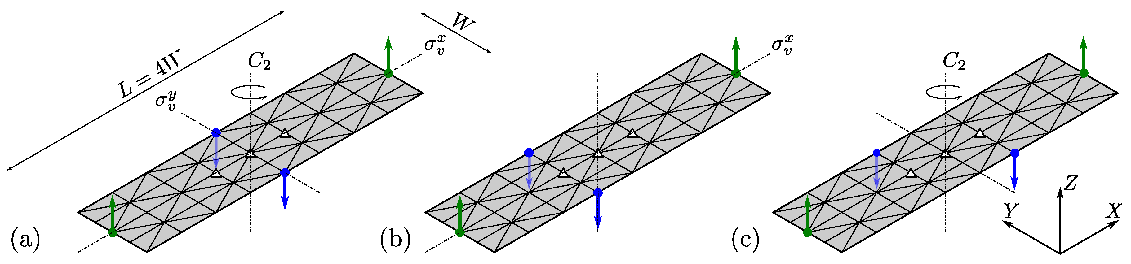
The problem setup for the optimization runs is illustrated in Figure 2, where the common ground structure contains 108 truss elements, of which 84 correspond to fold lines (design variables). The fixed nodes (white triangles) in the ground structure are kept constant across all problems. Green circles and arrows designate the output nodes that are associated with a target/optimal positive Z direction on the same two nodes for each problem, and the Z component is set to 1 in the corresponding component of the vector in J. Two input nodes on the sides of the structure, marked with blue circles and arrows, exist for all problems, where a simple out of plane displacement in the negative Z dimension is prescribed, . The location of these nodes correspond to unique point symmetries about the principal axis of the structure, i.e., Z-axis of the center node. Vertical reflection symmetries, , and a rotational symmetry, , are considered in the three variant problems depicted in Figure 2. The first problem depicted in Figure 2a contains two vertical reflection symmetries, and , and a rotational symmetry, , while Figure 2b preserves only a single vertical reflection symmetry, . The third problem contains only a rotational symmetry, and results in a subsequent twist actuation.
For each combination of input/output nodes, the downward actuation is varied as in increments of , and the constraint on the number of fold lines is varied as in increments of 0.1. This results in 25 optimization runs for each problem (total of 75 optimization runs). For all problems, , MPa, m, N and N. This corresponds to a stiffness ratio of near unity, which we have shown in prior work [34] corresponds to modes of deformation that favor facet stretching to facet bending. This material property ratio has been shown to limit the existence of bifurcations while loading, further limiting ill-conditioned minimization problems. The degree of stiffness naturally scales to even softer materials given the consideration of only elastic deformation through both geometric and material scaling, and the preference for facet stretching at large deformation is expected to mimic origami designs incorporating elastomeric materials. While input actuation is prescribed as a downward Z displacement, a single linear actuator connecting these nodes parallel to the Y could emulate this motion in practice. All optimization runs continue until convergence, i.e., the relative change of the objective function is less than (near numerical precision), and all runs converge in less than 100 iterations.
3.2. Small Displacement Optimization Results
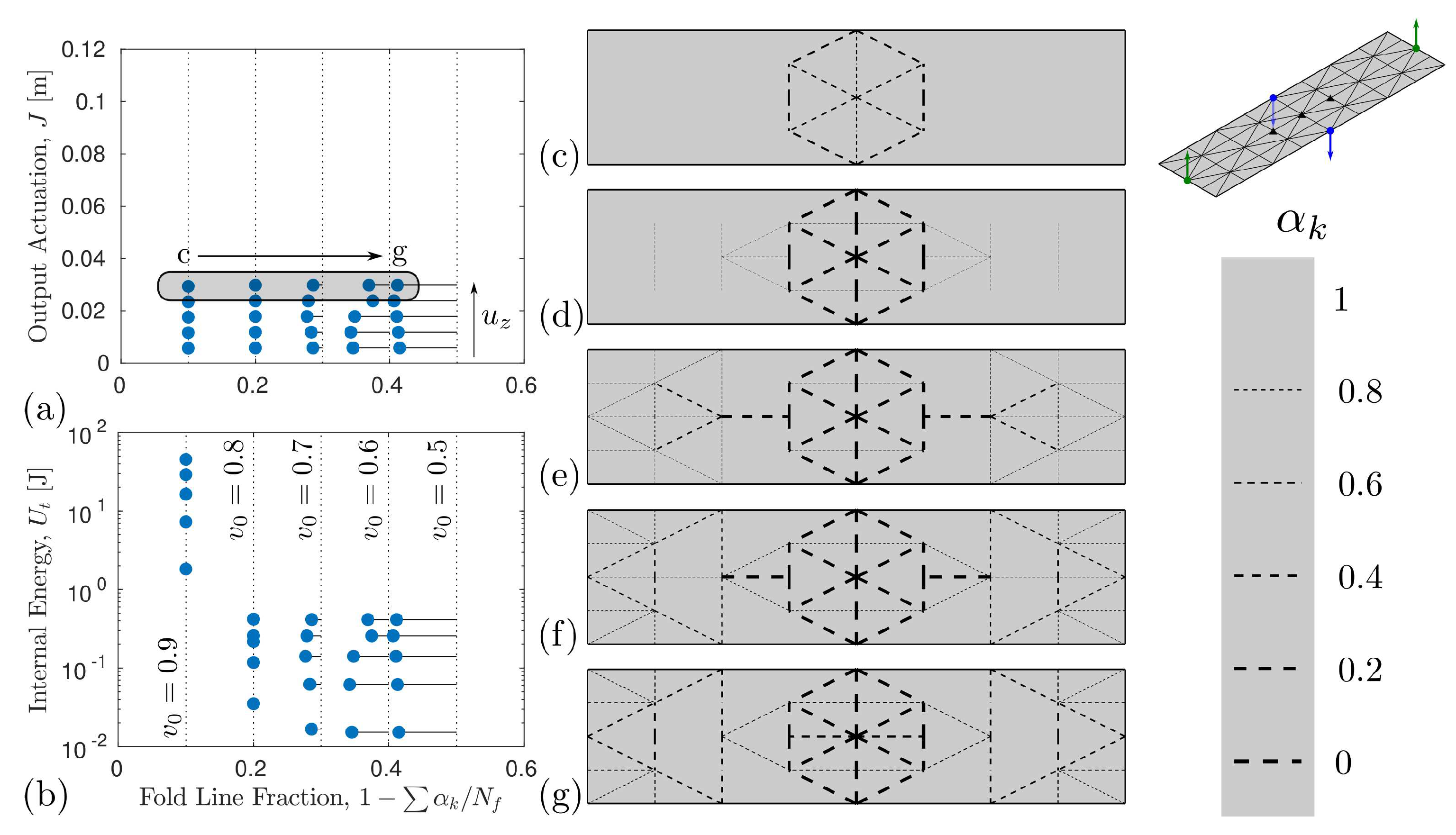
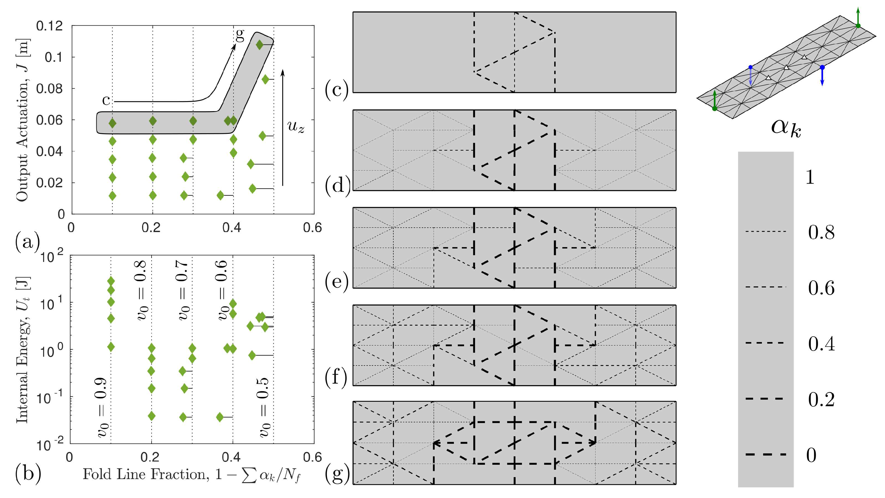
A summary of all optimization runs are presented in Figure 3, Figure 4 and Figure 5, with the amount of actuation and internal energy of the discovered pattern depicted for each run in (a and b). The resulting fold patterns for each constraint is shown in (c–g) for , as similar patterns were observed for lower . Each figure also contains a scale bar depicting the correlation between line thickness/dash length in each fold stiffness distribution pattern in (c–g) and the design variable, , in each truss element.
The optimization results for the problem with a rotational and two vertical reflection symmetries (problem setup in Figure 2a) is shown in Figure 3. A similar symmetric hexagonal pattern reflecting all symmetry groups is found in each of the optimized topologies (see Figure 3c–g). This common inner actuator component results in a similar performance as is increased as demonstrated by the near horizontal alignment of the output actuation as the number of fold lines increases. Figure 3a shows similar performance despite soft fold lines being added outside of the inner hexagonal pattern. A significant energy decrease does occur as the number of allowable fold lines is increased, changing from 0.9 to 0.8. Recall the fold fraction constraint is defined as , and the fraction of fold lines for a given topology is . There are 16 truss elements in the hexagonal pattern. Each fold stiffness/design variable cannot fully approach with () as the fold line constraint equals when all 16 truss elements are softened completely. Therefore, the internal energy of the patterns optimized with are higher due to the higher fold stiffnesses. The optimized designs with more restrictive constraints on the number fold lines (higher and smaller fold line fraction) are near the boundary of the constraint function g, while the patterns resulting when was set lower do not reach the constraint boundary. The constraint boundary for each set of problem is designated with the vertical dotted lines in Figure 3a,b. This has been observed in our prior optimization work with linear origami truss models [33,39].
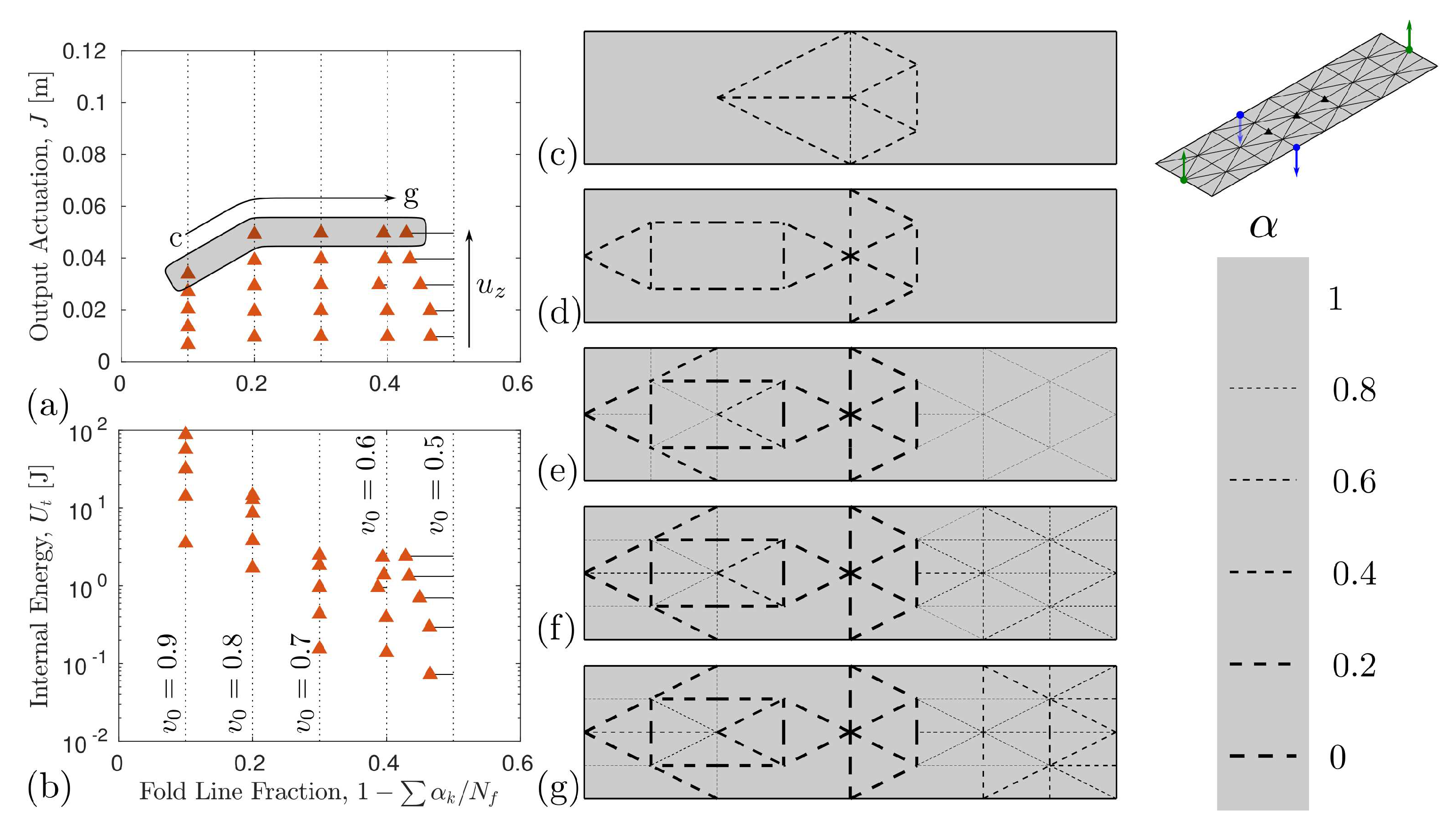
When one of the vertical reflection symmetries and the rotational symmetry are removed due to offset of the input actuation nodes for the problem depicted in Figure 2b, the resulting pattern respects the single vertical reflection symmetry, , and results in asymmetry due to the input actuation offset. The resulting patterns and summary of results for this case are presented in Figure 4. In contrast to the prior example where the core pattern in the center of the design was preserved as more folds are added to the design, the core topologies change as decreases. This transition also results in a more gradual decrease in the internal energy as fraction of fold lines increases (see Figure 4b). This also corresponds to varying performance changes as the fold line complexity constraint is relaxed (note kink in output actuation in Figure 4a).
For the last problem considered, a fold pattern with only the rotational symmetry, , results in a twist motion. The corresponding fold patterns discovered are depicted in Figure 5. Similar to the results with the single vertical reflection symmetries (Figure 4), the discovered patterns with rotational symmetry have a changing inner actuator topology as the fraction of fold lines increases. For the system with the largest number of active fold lines, the objective has a significant improvement in the output actuation objective, but at the cost of increases in the internal energy (see rightmost data points in Figure 5a,b). Additionally, a sharp decrease in the internal energy is observed when decreases from 0.9 to 0.8 (fold line fraction of ∼0.1 and ∼0.2, respectively), as there are 14 fold lines in the common fold lines and results in when these common fold lines are all fully soft ().
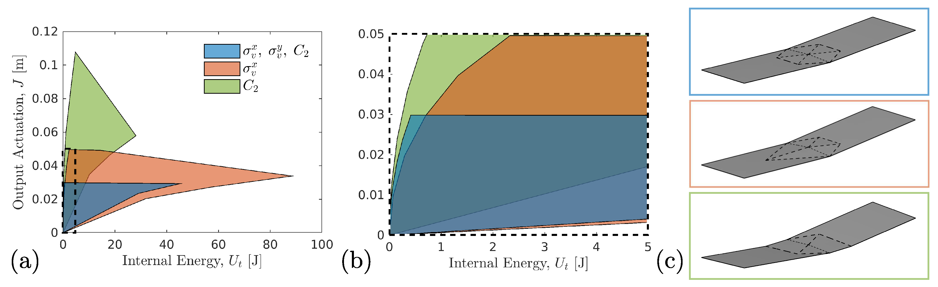
To compare all optimized fold patterns, all data is projected into the energy/output actuation performance space and compared in Figure 6. Optimal performance is considered the upper left quadrant of Figure 6a, where the fold topologies produce larger actuation at lower energy cost. The patterns with only rotational symmetry (green patch) result in the optimal performance followed by the patterns with a single vertical symmetry (red patch) and then the hexagonal pattern containing two vertical reflection and rotational symmetries (blue patch). The actuated patterns from the optimization runs with the most restrictive fold line complexity constraint () are shown in Figure 6c, where the largest upward actuation of the actuator arms is seen for the twist actuator pattern. When zoomed into the projected performance space with lowest energies (see Figure 6b), there is a regime where the symmetric hexagonal family of patterns outperforms the asymmetric patterns with only a single vertical reflection symmetry.
This study illustrates that the symmetries in the mechanics of the problem setup are reflected in the optimized result. This follows a mathematical proof by Guo et al. [43], where topology symmetries matched mechanical and objective function symmetries with gradient based approaches for convex problems. While only mechanical symmetries (actuated input conditions) were considered in the presented examples, we have confirmed that the twist pattern obtained with a rotational symmetry in the input can also be obtained if the symmetry is reflected in only the objective function. While the gradient-based results here are not guaranteed to to find the optimal performing patterns given the apparent non-convexity of the problem, the symmetries of the problem can be leveraged to meet the actuation requirement of an actuating compliant mechanism. Consideration of both the kinematics and energy of the designs from high-throughput optimization studies, as conducted here, allows for design of compliant mechanisms with varying degrees of complexity, and information about the energetics and motions during design selection can be simultaneously leveraged given the operational goal of the actuator.
3.3. Large Displacement Analysis
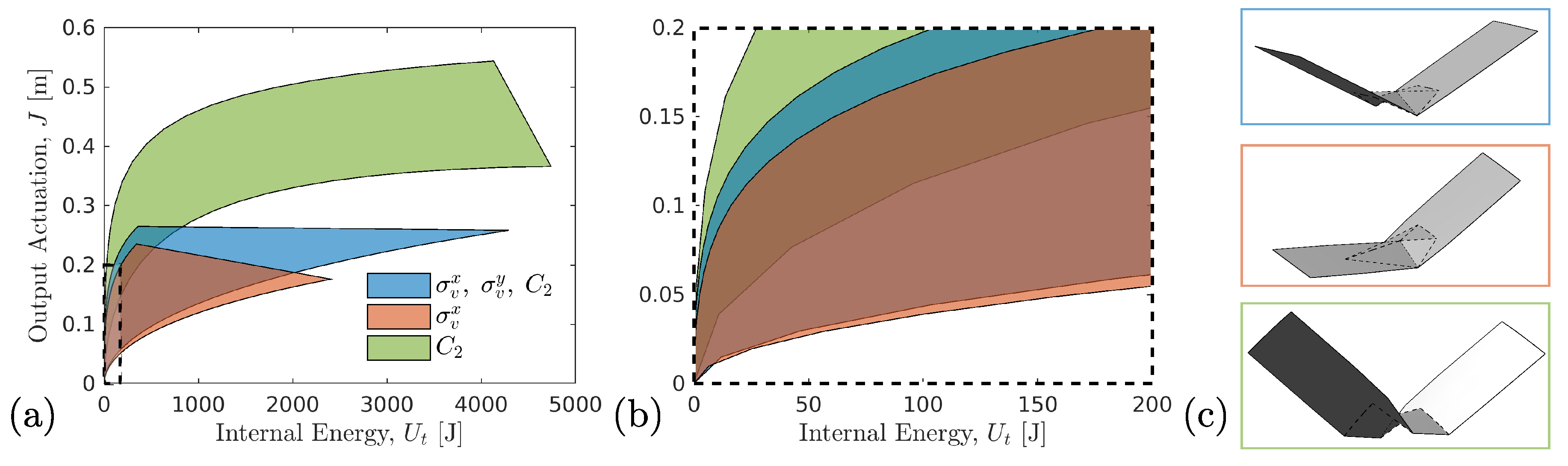
To determine the performance of the optimized topologies at larger rotations and displacements, all optimized fold patterns from the prior subsection are then analyzed considering actuation up to , or ten times more than the small displacement optimization runs. The entire nonlinear loading paths are then projected into the same energy/output actuation performance space as in Figure 6. The resulting projections in Figure 7 similarly show that the twist actuator has optimal performance but by an even greater margin. The superior performance is clearly seen in the depictions of select patterns in Figure 7c. However, patterns preserving both vertical and rotational symmetries show more efficient performance relative to the patterns with only a single vertical reflection symmetry in contrast with the small displacement behavior exhibited in Figure 6. The material property selection in this work results in fold patterns that are dominated by folding/facet bending energy in small displacement regimes, while the stretching energy becomes the dominant deformation mechanism at large deformation. All analysis in these optimization runs has been conducted with a single material property selection. However, expanding the parameter exploration space to different material deformation modes will naturally expand these performance regimes and yield further tuning of the material behavior. Based on our recent work [34], it is expected that materials with stiffer facets would yield improved performance, and the optimal fold line topologies are likely to change. While stretchable facets such as the ones considered may limit performance benefits of stiff faceted systems, the compliance allows for improved tolerance given uncertainties in external loading conditions.
4. Multistability of Unit Actuators
In our optimization analysis, the flat state corresponds to a single equilibrium state. It is a rich design space reference point for thin sheets as there are numerous bifurcating fold paths that often intersect at the flat state. However, by creating a non-flat equilibrium state after folding, either through introducing plastic deformation in the material or tuning the reference angle of the torsion spring in an assembled device, there are often local instabilities that can access additional stable states. One of the simplest well-studied vertex inversion instabilities in origami is the snap-through bifurcation of the waterbomb structure. The nonlinear mechanics and mechanisms for actuating this structure through external gradient fields (humidity, thermal, magnetic, etc.) is provided in many works [9,30,36,44]. In light of this knowledge, we probe the fundamental actuating fold patterns discovered here for additional stable states after folding.
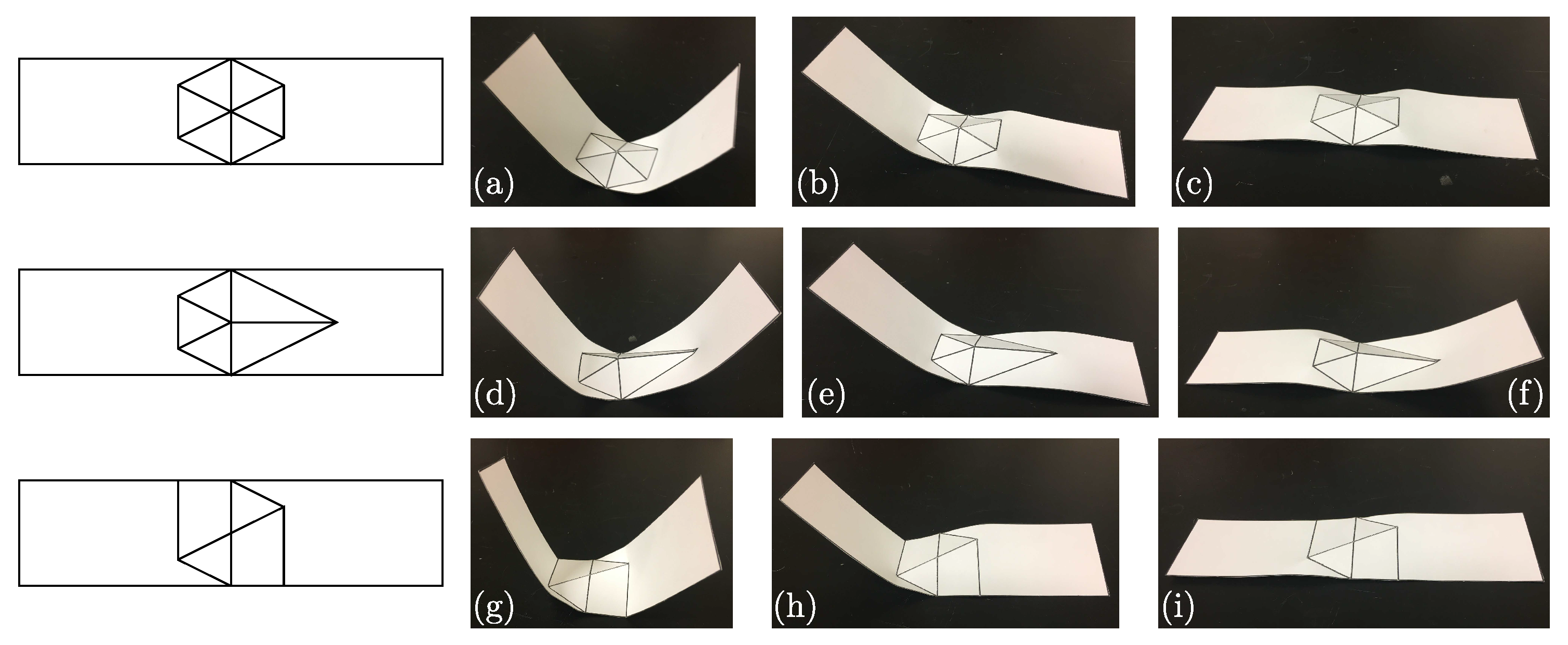
The simplest actuating mechanisms discovered in Section 3.2 with the least number of fold lines were formed into physical prototypes using 80 lb. cardstock, where scoring with a sharp blade along the fold lines enables accurate representation of the folding behavior. The scoring effectively both softens the material through material thinning and concentrates the plastic deformation during folding to the fold line. After scoring, these patterns were manually folded to qualitatively match the actuated shape observed in the nonlinear simulation. The resulting folded structures are depicted in Figure 8, with the equilibrium state after folding shown in Figure 8a,d,g, respectively, for each fold pattern. For all patterns, each side or arm of the structure has a local snap-through instability that can be accessed through a small mechanical perturbation, resulting in multiple stable configurations. These stable configurations are depicted in the additional sub-figures of Figure 8 and can be used to achieve macroscopic shape change, which is demonstrated in the following section. These vertex inversion instabilities can be accessed by concentrating active material at the fold line/vertex that undergoes inversion to overcome the energy barrier and snap to the additional stable state.
5. Networks of Unit Actuators
One of the appealing aspects of origami is the inherent modularity of certain patterns given the natural symmetries and tessellations that occur. As for the ground structures considered in our optimization runs, this modularity is preserved and enables the study of networks of these discovered patterns. The networked behavior of select origami patterns are explored through demonstration in cardstock using fabrication methods described in the prior section.
Figure 9 describes the shape change and multistable configurations possible for a continuous looped network of the fold pattern containing both reflection and rotation symmetries. Figure 9a shows four units linked together, where the folding orientation (mountain-valley assignment) alternates between up and down (marked blue and green in schematic) to form a cyclic network. The equilibrium configuration exhibits a dumbbell like shape. When networked together, the local instabilities demonstrated in Figure 8b,c can be triggered to transform the configuration. When the nodes marked I are inverted (instability demonstrated in Figure 8c), the dumbbell expands to an oval with less curvature variation. Meanwhile, nodes marked can be triggered to the instability shown in Figure 8b to create a rectangular shape. This demonstration shows that these fold patterns provide utility beyond simple actuation, as it can be networked to drive macroscopic shape change through triggering local snap-through instabilities. In addition to shape change, the networked system can also be actuated at nodes I to create a different mode of macroscopic motion for the closed loop network, as demonstrated in Figure 9d. The mode of deformation does not lead to an additional equilibrium state but provides a motion that could be controlled through a simple linear actuator placed with nodes marked I joined at the center, i.e., driven by a single degree of freedom. This expansion is also observed for larger networks as demonstrated by the six units in a connected loop with alternating mountain/valley orientation in Figure 9e.
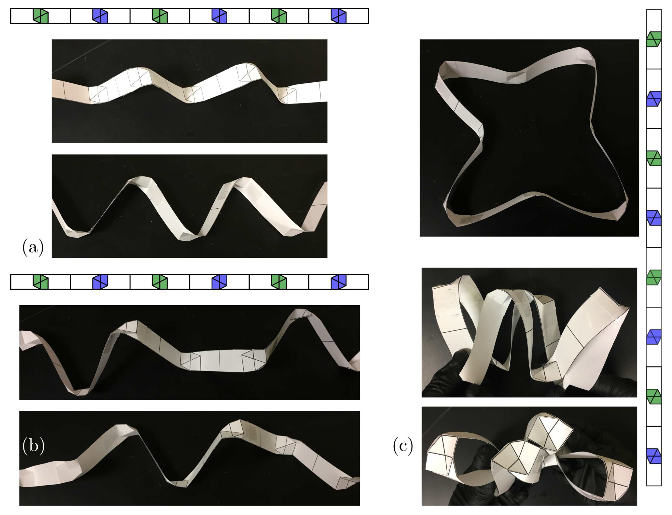
Networks composed of the twist design (pattern optimized with rotational symmetry) offer additional modes of actuation. This pattern, given its rotational symmetry, allows more variant combinations as both the mountain valley orientation and the fold pattern orientation to be arranged can be arranged uniquely. Simple linear actuation of two different orientations are demonstrated in Figure 10a,b. The linear network in Figure 10a creates a linear actuating motion with an offset displacement perpendicular to the networked dimension. Meanwhile, when the fold pattern is also alternated, a twisting motion is achieved (see Figure 10b). When a cycle of this fold pattern is formed as shown in Figure 10c, the network can move from an in-plane loop to a compact configuration where the arms of the pattern align in the perpendicular direction. The networks depicted in Figure 9 and Figure 10 represent a subset of the actuator connectivities and stable configuration combinations possible. The diverse modularity of these origami actuators presents an opportunity to tune the network for robotics needs, such as specific 3D motions and the energetics of the specific equilibrium states.
6. Conclusions
Through topology optimization, fold patterns of compliant origami mechanisms for amplification of a simple input motion were discovered. It was observed that symmetries in the problem setup were reflected in the optimized result, which enables targeted design for soft actuator applications. In this study, multiple vertical reflection and rotational symmetries in the problem were explored. Performance maps in both the small and large actuation regimes were created to illustrate the energetic and performance trade-off of each design. Patterns exhibiting a twist motion through enforcement of rotational symmetry exhibited superior performance in both the small and large displacement (actuation) regime. The material properties explored here considered systems showing preference toward facet stretching over facet bending in the large displacement regime. However, the framework enables substantial tuning of material properties for a given material system. Tuning the material to promote facet bending is likely to increase the actuator performance. The number of accessible instabilities may increase when allowing facet bending, which leads to a challenging optimization problem with many bifurcating load paths. While increasing the design space complexity through addition of bifurcation paths could lead to improved performance, additional parameters need to be introduced as design variables for controlling the instabilities in manufactured systems to ensure that optimal paths are consistently followed.
After exploring optimal fold patterns through topology optimization, select designs were fabricated and experimentally studied for existence of multistable configurations. All patterns studied here exhibited multistable configurations that could be accessed via local snap-through instabilities of select folds/vertices. Origami unit cells have demonstrated the ability to perform complex motions and actions in actuating systems including grippers, stent deployment, and linear snake-like motion, just to name a few, and the multistable nature increases their utility. The unit cells discovered here add to this database of actuating fold patterns, and initial demonstrations show the ability to achieve macroscopic shape change. Beyond utilizing the multistable states for large and quick reconfigurations, these multistabilities can be leveraged as a mechanism for storing information locally within the material for mechano-logic applications [9]. Combined with environmentally responsive materials, e.g., light, heat, humidity, etc., these actuating networks could respond to changes in the surroundings and/or communicate this information throughout a complex structure for adaptive automated response.
Soft robotics applications will continue to increase in number and utility as the material sets and actuation design tools for them broaden. The origami mechanisms and targeted symmetry design methodology presented in this study provides an initial assessment of origami actuator classes and provides a framework for the discovery of future soft, actuating mechanisms.
Author Contributions
Conceptualization and supervision of study by P.B., A.P., and D.H.; Optimization studies and analysis performed by A.G. and G.W.; Sample preparation and experimental demonstration by A.G.; All authors contributed to manuscript preparation and editing.
Funding
A.G., K.F., A.P. and P.B. acknowledge funding support from the Air Force Office of Scientific Research (AFOSR) under contract LRIR 16RXCOR319. G.W. and D.H. acknowledge funding support from the National Science Foundation (NSF) and AFOSR under grant EFRI-ODISSEI 1240483. A portion of computations was enabled through Ohio Supercomputing Center allocation.
Conflicts of Interest
The authors declare no conflict of interest.
References
- Miriyev, A.; Stack, K.; Lipson, H. Soft material for soft actuators. Nat. Commun. 2017, 8, 596. [Google Scholar] [CrossRef]
- Li, T.; Li, G.; Liang, Y.; Cheng, T.; Dai, J.; Yang, X.; Liu, B.; Zeng, Z.; Huang, Z.; Luo, Y.; et al. Fast-moving soft electronic fish. Sci. Adv. 2017, 3, e1602045. [Google Scholar] [CrossRef] [PubMed] [Green Version]
- Guin, T.; Settle, M.J.; Kowalski, B.A.; Auguste, A.D.; Beblo, R.V.; Reich, G.W.; White, T.J. Layered liquid crystal elastomer actuators. Nat. Commun. 2018, 9, 2531. [Google Scholar] [CrossRef] [PubMed]
- Polygerinos, P.; Correll, N.; Morin, S.A.; Mosadegh, B.; Onal, C.D.; Petersen, K.; Cianchetti, M.; Tolley, M.T.; Shepherd, R.F. Soft robotics: Review of fluid-driven intrinsically soft devices; manufacturing, sensing, control, and applications in human-robot interaction. Adv. Eng. Mater. 2017, 19, 1700016. [Google Scholar] [CrossRef]
- Culbertson, H.; Schorr, S.B.; Okamura, A.M. Haptics: The Present and Future of Artificial Touch Sensation. Ann. Rev. Control Robot. Auton. Syst. 2018, 1, 385–409. [Google Scholar] [CrossRef]
- Rogers, J.; Huang, Y.; Schmidt, O.G.; Gracias, D.H. Origami mems and nems. Mrs Bull. 2016, 41, 123–129. [Google Scholar] [CrossRef]
- Lee, D.Y.; Kim, J.S.; Kim, S.R.; Koh, J.S.; Cho, K.J. The deformable wheel robot using magic-ball origami structure. In Proceedings of the ASME 2013 International Design Engineering Technical Conferences and Computers and Information in Engineering Conference, Portland, OR, USA, 4–7 August 2013; p. V06BT07A040. [Google Scholar]
- Lee, D.Y.; Kim, S.R.; Kim, J.S.; Park, J.J.; Cho, K.J. Origami wheel transformer: A variable-diameter wheel drive robot using an origami structure. Soft Robot. 2017, 4, 163–180. [Google Scholar] [CrossRef]
- Treml, B.; Gillman, A.; Buskohl, P.; Vaia, R. Origami mechanologic. Proc. Natl. Acad. Sci. USA 2018, 115, 6916–6921. [Google Scholar] [CrossRef]
- Babaee, S.; Overvelde, J.T.; Chen, E.R.; Tournat, V.; Bertoldi, K. Reconfigurable origami-inspired acoustic waveguides. Sci. Adv. 2016, 2, e1601019. [Google Scholar] [CrossRef] [Green Version]
- Silverberg, J.L.; Evans, A.A.; McLeod, L.; Hayward, R.C.; Hull, T.; Santangelo, C.D.; Cohen, I. Using origami design principles to fold reprogrammable mechanical metamaterials. Science 2014, 345, 647–650. [Google Scholar] [CrossRef]
- Filipov, E.T.; Tachi, T.; Paulino, G.H. Origami tubes assembled into stiff, yet reconfigurable structures and metamaterials. Proc. Natl. Acad. Sci. USA 2015, 112, 12321–12326. [Google Scholar] [CrossRef] [PubMed]
- Peraza-Hernandez, E.A.; Hartl, D.J.; Malak, R.J., Jr.; Lagoudas, D.C. Origami-inspired active structures: A synthesis and review. Smart Mater. Struct. 2014, 23, 094001. [Google Scholar] [CrossRef]
- Tolley, M.T.; Felton, S.M.; Miyashita, S.; Aukes, D.; Rus, D.; Wood, R.J. Self-folding origami: shape memory composites activated by uniform heating. Smart Mater. Struct. 2014, 23, 094006. [Google Scholar] [CrossRef]
- Kohlmeyer, R.R.; Buskohl, P.R.; Deneault, J.R.; Durstock, M.F.; Vaia, R.A.; Chen, J. Shape-reprogrammable polymers: Encoding, erasing, and re-encoding. Adv. Mater. 2014, 26, 8114–8119. [Google Scholar] [CrossRef] [PubMed]
- Peraza-Hernandez, E.; Hartl, D.; Galvan, E.; Malak, R. Design and optimization of a shape memory alloy-based self-folding sheet. J. Mech. Des. 2013, 135, 111007. [Google Scholar] [CrossRef]
- Plucinsky, P.; Kowalski, B.A.; White, T.J.; Bhattacharya, K. Patterning nonisometric origami in nematic elastomer sheets. Soft Matter 2018, 14, 3127–3134. [Google Scholar] [CrossRef] [PubMed] [Green Version]
- Fuchi, K.; Ware, T.H.; Buskohl, P.R.; Reich, G.W.; Vaia, R.A.; White, T.J.; Joo, J.J. Topology optimization for the design of folding liquid crystal elastomer actuators. Soft Matter 2015, 11, 7288–7295. [Google Scholar] [CrossRef]
- Na, J.H.; Evans, A.A.; Bae, J.; Chiappelli, M.C.; Santangelo, C.D.; Lang, R.J.; Hull, T.C.; Hayward, R.C. Programming reversibly self-folding origami with micropatterned photo-crosslinkable polymer trilayers. Adv. Mater. 2015, 27, 79–85. [Google Scholar] [CrossRef]
- Miskin, M.Z.; Dorsey, K.J.; Bircan, B.; Han, Y.; Muller, D.A.; McEuen, P.L.; Cohen, I. Graphene-based bimorphs for micron-sized, autonomous origami machines. Proc. Natl. Acad. Sci. USA 2018, 115, 466–470. [Google Scholar] [CrossRef]
- Demaine, E.D.; Tachi, T. Origamizer: A practical algorithm for folding any polyhedron. In Proceedings of the the 33rd International Symposium on Computational Geometry, Brisbane, Australia, 4–7 July 2017; Volume 77. [Google Scholar]
- Tachi, T. Simulation of rigid origami. Origami 2009, 4, 175–187. [Google Scholar]
- Lang, R.J. Treemaker 4.0: A Program for Origami Design. Available online: http://www.langorigami.com/wp-content/uploads/2015/09/TreeMkr40.pdf (accessed on 16 November 2018).
- Evans, T.A.; Lang, R.J.; Magleby, S.P.; Howell, L.L. Rigidly foldable origami gadgets and tessellations. R. Soc. Open Sci. 2015, 2, 150067. [Google Scholar] [CrossRef] [PubMed] [Green Version]
- Bowen, L.A.; Grames, C.L.; Magleby, S.P.; Howell, L.L.; Lang, R.J. A classification of action origami as systems of spherical mechanisms. J. Mech. Des. 2013, 135, 111008. [Google Scholar] [CrossRef]
- Chen, Y.; Peng, R.; You, Z. Origami of thick panels. Science 2015, 349, 396–400. [Google Scholar] [CrossRef] [PubMed]
- Aukes, D.M.; Goldberg, B.; Cutkosky, M.R.; Wood, R.J. An analytic framework for developing inherently-manufacturable pop-up laminate devices. Smart Mater. Struct. 2014, 23, 094013. [Google Scholar] [CrossRef]
- Schenk, M.; Guest, S.D. Origami folding: A structural engineering approach. In Origami 5: Fifth International Meeting of Origami Science, Mathematics, and Education; CRC Press: Boca Raton, FL, USA, 2011; pp. 291–304. [Google Scholar]
- Filipov, E.; Liu, K.; Tachi, T.; Schenk, M.; Paulino, G. Bar and hinge models for scalable analysis of origami. Int. J. Solids Struct. 2017, 124, 26–45. [Google Scholar] [CrossRef] [Green Version]
- Gillman, A.; Fuchi, K.; Buskohl, P. Truss-based nonlinear mechanical analysis for origami structures exhibiting bifurcation and limit point instabilities. Int. J. Solids Struct. 2018, 147, 80–93. [Google Scholar] [CrossRef]
- Fuchi, K.; Buskohl, P.R.; Joo, J.J.; Reich, G.W.; Vaia, R.A. Numerical analysis of origami structures through modified frame elements. In Origami6; Miura, K., Kawasaki, T., Tachi, T., Uehara, R., Lang, R.J., Wang-Iverson, P., Eds.; American Mathematical Society: Providence, RI, USA, 2015; pp. 385–395. [Google Scholar]
- Hernandez, E.A.P.; Hartl, D.J.; Malak, R.J.; Akleman, E.; Gonen, O.; Kung, H.W. Design tools for patterned self-folding reconfigurable structures based on programmable active laminates. J. Mech. Robot. 2016, 8, 031015. [Google Scholar] [CrossRef]
- Fuchi, K.; Buskohl, P.R.; Bazzan, G.; Durstock, M.F.; Reich, G.W.; Vaia, R.A.; Joo, J.J. Origami actuator design and networking through crease topology optimization. J. Mech. Des. 2015, 137, 091401. [Google Scholar] [CrossRef]
- Gillman, A.; Fuchi, K.; Buskohl, P. Discovering sequenced origami folding through nonlinear mechanics and topology optimization. J. Mech. Des. 2018. [Google Scholar] [CrossRef]
- Waitukaitis, S.; Menaut, R.; Chen, B.G.; van Hecke, M. Origami multistability: From single vertices to metasheets. Phys. Rev. Lett. 2015, 114, 055503. [Google Scholar] [CrossRef]
- Hanna, B.H.; Lund, J.M.; Lang, R.J.; Magleby, S.P.; Howell, L.L. Waterbomb base: a symmetric single-vertex bistable origami mechanism. Smart Mater. Struct. 2014, 23, 094009. [Google Scholar] [CrossRef]
- Demaine, E.D.; Demaine, M.L.; Hart, V.; Price, G.N.; Tachi, T. (Non) existence of pleated folds: How paper folds between creases. In Graphs and Combinatorics; Springer: Berlin, Germany, 2011; Volume 27, pp. 377–397. [Google Scholar]
- Dudte, L.H.; Vouga, E.; Tachi, T.; Mahadevan, L. Programming curvature using origami tessellations. Nat. Mater. 2016, 15, 583. [Google Scholar] [CrossRef] [PubMed]
- Fuchi, K.; Buskohl, P.R.; Bazzan, G.; Durstock, M.F.; Reich, G.W.; Vaia, R.A.; Joo, J.J. Design Optimization Challenges of Origami-Based Mechanisms With Sequenced Folding. J. Mech. Robot. 2016, 8, 051011. [Google Scholar] [CrossRef]
- Gill, P.; Murray, W.; Wright, M. Numerical Linear Algebra and Optimization; Addison Wesley: Boston, MA, USA, 1991. [Google Scholar]
- MATLAB. Version 9.1.0 (R2016b), The MathWorks Inc.: Natick, MA, USA, 2016.
- Greco, M.; Gesualdo, F.; Venturini, W.; Coda, H. Nonlinear positional formulation for space truss analysis. Finite Elem. Anal. Des. 2006, 42, 1079–1086. [Google Scholar] [CrossRef]
- Guo, X.; Ni, C.; Cheng, G.; Du, Z. Some symmetry results for optimal solutions in structural optimization. Struct. Multidiscip. Optim. 2012, 46, 631–645. [Google Scholar] [CrossRef]
- Bowen, L.; Springsteen, K.; Feldstein, H.; Frecker, M.; Simpson, T.W.; von Lockette, P. Development and validation of a dynamic model of magneto-active elastomer actuation of the origami waterbomb base. J. Mech. Robot. 2015, 7, 011010. [Google Scholar] [CrossRef]
Figure 1.
Overview of optimization framework. Inset images in flowchart (from top to bottom) show the initialization of the ground structure with uniform fold stiffness, unit truss element formulation and boundary conditions described on the ground structure, actuated design where objective function and constraints are evaluated, and design update on the fold topology through fold stiffness changes as determined from the sensitivity analysis.

Figure 2.
Optimization problem setup for ground structure with different symmetries: (a) two vertical reflection symmetries, and , and a rotational symmetry, ; (b) single vertical reflection symmetry, , (c) rotational symmetry, . The vertical reflection symmetry, refers to symmetry about the X–Z plane, the vertical reflection symmetry, , refers to symmetry about the Y–Z plane, and the rotational symmetry, refers to the rotational operation about the Y–Z plane. White triangles refer to fixed nodes in the structure, blue arrows/circles refer to actuated nodes, and green arrows/circles refer to output nodes in objective function. Actuation and output directions are in the Z dimension.

Figure 3.
Summary of optimization results for patterns with a rotational and two vertical reflection symmetries (see problem setup in top right of figure). (a) resulting objective function value of optimized patterns for varying fold line complexity and input actuation ; (b) internal energy of optimized patterns. Resulting fold patterns from optimization runs for largest input displacement considered are depicted in (c–g), (c) , (d) , (e) , (f) , and (g) . Fold topologies shown correspond to optimization runs highlighted by gray box in (a). Scale bar depicts correlation of line thickness/dash length to design variable , where corresponds to a soft hinge (fold line, ) and to a stiff hinge ().

Figure 4.
Summary of optimization results for patterns with single vertical reflection symmetry, , (see problem setup in top right of figure). (a) Resulting objective function value of optimized patterns for varying fold line complexity and input actuation . (b) Internal energy of optimized patterns. Resulting fold patterns from optimization runs for largest input displacement considered are depicted in (c–g), (c) , (d) , (e) , (f) , and (g) . Fold topologies shown correspond to optimization runs highlighted by gray box in (a). Scale bar depicts correlation of line thickness/dash length to design variable , where corresponds to a soft hinge (fold line, ) and to a stiff hinge ().

Figure 5.
Summary of optimization results for patterns with rotational symmetry (see problem setup in top right of figure). (a) resulting objective function value of optimized patterns for varying fold line complexity and input actuation ; (b) internal energy of optimized patterns. Resulting fold patterns from optimization runs for largest input displacement considered are depicted in (c–g), (c) , (d) , (e) , (f) , and (g) . Fold topologies shown correspond to optimization runs highlighted by gray box in (a). Scale bar depicts correlation of line thickness/dash length to design variable , where corresponds to a soft hinge (fold line, ) and to a stiff hinge ().

Figure 6.
Summary of optimized fold pattern performance from results in Figure 3, Figure 4 and Figure 5. (a) performance map of all optimized designs in actuation-energy space; (b) zoomed view of (a); (c) actuated designs for . The optimized designs with only rotational symmetry (green patch) have the optimal amount of actuation with lower energy cost.

Figure 7.
Results of large displacement analysis for fold patterns optimized via small displacement analysis. (a) performance map of all optimized designs in actuation-energy space; (b) zoomed-in view of (a); (c) actuated designs for . The rotational symmetry optimized designs (green patch) have the optimal amount of actuation with lower energy cost. The patterns with all symmetries (blue patch) have more optimal performance relative to the designs with only a single vertical reflection symmetry, which is in contrast to small displacement actuation results in Figure 6.

Figure 8.
Multistable configurations of core actuating topologies from Section 3. (a) equilibrium folded state corresponding to symmetric actuator with a rotational and two vertical reflection symmetries; (b,c) stable pop-through instabilities exist for each arm in the pattern; (d) equilibrium folded state corresponding to asymmetric actuator with single vertical reflection symmetry and asymmetric actuation of each arm; (e,f) stable pop-through instabilities exist for each arm in the pattern; (g) equilibrium folded state corresponding to an actuator with only rotational symmetry resulting in twist motion; (h,i) stable pop-through instabilities exist for each arm in the pattern.

Figure 9.
Shape change and actuation of networks composed of symmetric actuator result from Figure 3c. (a) loop network of four actuators with alternating orientations; (b) expanded oval shape from (a) accessed through symmetric pop-through instability (see Figure 8c) of nodes labeled I; (c) expanded rectangular shape accessed through asymmetric pop-through instability (see Figure 8b) of nodes labeled II; (d) actuating mechanism for 4-unit network shown in (a); (e) actuating mechanism for 6-unit network. The networks in (d,e) are accessed through actuation of the center elements.

Figure 10.
Linear actuator networks and loops composed of twist actuator with rotational symmetry. (a) linear actuating network where fold patterns are aligned but orientation of folds are alternating. This results in an offset linear motion when the network is stretched/compressed; (b) linear actuator with alternating orientation of fold pattern. The rotated fold patterned results in a twisting motion when linearly stretched/compressed; (c) actuation of loop network of twist actuators. This looped network is composed of alternating pairs with the same fold pattern and alternating orientation. With actuation of every other unit, the shape is contracted and reoriented (bottom) into the direction perpendicular to the equilibrium expanded state (top).

© 2018 by the authors. Licensee MDPI, Basel, Switzerland. This article is an open access article distributed under the terms and conditions of the Creative Commons Attribution (CC BY) license (http://creativecommons.org/licenses/by/4.0/).
Share and Cite
MDPI and ACS Style
Gillman, A.; Wilson, G.; Fuchi, K.; Hartl, D.; Pankonien, A.; Buskohl, P. Design of Soft Origami Mechanisms with Targeted Symmetries. Actuators 2019, 8, 3. https://doi.org/10.3390/act8010003
AMA Style
Gillman A, Wilson G, Fuchi K, Hartl D, Pankonien A, Buskohl P. Design of Soft Origami Mechanisms with Targeted Symmetries. Actuators. 2019; 8(1):3. https://doi.org/10.3390/act8010003
Chicago/Turabian StyleGillman, Andrew, Gregory Wilson, Kazuko Fuchi, Darren Hartl, Alexander Pankonien, and Philip Buskohl. 2019. "Design of Soft Origami Mechanisms with Targeted Symmetries" Actuators 8, no. 1: 3. https://doi.org/10.3390/act8010003
Note that from the first issue of 2016, this journal uses article numbers instead of page numbers. See further details here.