 Sheikh Mohammad Shavik
 Zhenxiang Jiang
 Seungik Baek
 Lik Chuan Lee
- Department of Mechanical Engineering, Michigan State University, East Lansing, MI, United States
While it has long been recognized that bi-directional interaction between the heart and the vasculature plays a critical role in the proper functioning of the cardiovascular system, a comprehensive study of this interaction has largely been hampered by a lack of modeling framework capable of simultaneously accommodating high-resolution models of the heart and vasculature. Here, we address this issue and present a computational modeling framework that couples finite element (FE) models of the left ventricle (LV) and aorta to elucidate ventricular—arterial coupling in the systemic circulation. We show in a baseline simulation that the framework predictions of (1) LV pressure—volume loop, (2) aorta pressure—diameter relationship, (3) pressure—waveforms of the aorta, LV, and left atrium (LA) over the cardiac cycle are consistent with the physiological measurements found in healthy human. To develop insights of ventricular-arterial interactions, the framework was then used to simulate how alterations in the geometrical or, material parameter(s) of the aorta affect the LV and vice versa. We show that changing the geometry and microstructure of the aorta model in the framework led to changes in the functional behaviors of both LV and aorta that are consistent with experimental observations. On the other hand, changing contractility and passive stiffness of the LV model in the framework also produced changes in both the LV and aorta functional behaviors that are consistent with physiology principles.
Introduction
The heart and vasculature are key components of the cardiovascular system that operate in tandem to deliver oxygen and nutrients to the human body. Physiological adaptation, deterioration, and/or malfunctioning of one component often affects the operation of the other. Indeed, optimal ventricular-arterial interaction (or coupling) is critical to the normal functioning of the cardiovascular system. Any deviations from optimal ventricular-arterial interaction in the cardiovascular system (as indexed by the ratio between arterial stiffness and ventricular elastance) are usually associated with heart diseases (Borlaug and Kass, 2011). In the pulmonary circulatory system, interactions between the right ventricle and the pulmonary vasculature are key determinants of the clinical course of pulmonary hypertension (Naeije and Manes, 2014), specifically, in the transition from compensated to decompensated remodeling. Similarly, in the systemic circulatory system, heart failure with preserved ejection (HFpEF) has been associated with a progressively impaired ventricular-arterial interaction between the left ventricle (LV) and the systemic arteries (Kawaguchi et al., 2003; Borlaug and Kass, 2011). Ventricular-arterial interaction is also reflected at the microstructural level. In particular, remodeling of the vasculature found in these diseases (e.g., smooth muscle hypertrophy/proliferation and deposition of the collagen) (Shimoda and Laurie, 2013; Giamouzis et al., 2016) are often accompanied by similar remodeling in the heart (e.g., myocyte hypertrophy and cardiac fibrosis) (Rain et al., 2013; Hill et al., 2014; Su et al., 2014).
Computational modeling is particularly useful for understanding ventricular-arterial interaction, especially as there are potentially many parameters that can affect this interaction bi-directionally. While ventricular-arterial interactions may be described using electrical analog (or lumped parameter) models of the cardiovascular system (Smith et al., 2004; Arts et al., 2005), the heart and vasculature in such models are represented using highly idealized electrical circuit elements such as resistor, capacitor, and voltage generator. It is difficult, if not impossible, to separate or distinguish between geometrical, material, and microstructural changes from the parameters of these electrical elements. Previous finite element (FE) modeling efforts of the cardiovascular system, however, have focused on either the heart or the vasculature. Specifically, FE models of the heart were developed either in isolation (Wenk et al., 2011; Lee et al., 2013; Gao et al., 2014; Genet et al., 2014), or coupled to an electrical analog of the circulatory system in open (Usyk et al., 2002; Trayanova et al., 2011; Wall et al., 2012; Lee et al., 2016; Xi et al., 2016) or closed loop fashions (Kerckhoffs et al., 2007; Shavik et al., 2017). In an open-loop circulatory modeling framework, the FE ventricular model is generally coupled to a Windkessel model via outlet boundary conditions to simulate the ejection of blood, while the filling and isovolumic phases are, respectively, simulated by increasing and constraining the ventricular cavity volume. Parameters in the modeling framework are then adjusted so that the four distinct cardiac phases form a closed pressure-volume loop. On the other hand, coupling the FE ventricular model to a closed loop circulatory modeling framework is (arguably) more physical since the total blood volume is naturally conserved in the cardiovascular system. Simulation of multiple cardiac cycles is required, however, to obtain a steady state solution. Conversely, FE models of the vasculature were developed either in isolation (Hsu and Bazilevs, 2011; Zeinali-Davarani et al., 2011) or coupled to simplified representation of the heart based on a time-varying elastance function (Kim et al., 2009; Lau and Figueroa, 2015). Although able to describe the heart or vasculature in greater details, these FE modeling frameworks cannot be used to simulate detailed bidirectional ventricular-arterial interactions e.g., how changes in the vasculature mechanical properties affect the deformation and function of the heart and vice versa.
To overcome these limitations, we describe here a novel computational framework that is capable of coupling high spatial resolution FE models of both the vasculature and the heart to describe bidirectional ventricular-arterial coupling in the systemic circulation. Using realistic geometries and microstructure of the LV and aorta, we show that the framework is able to reproduce features that are consistent with measurements made in both compartments. We also performed a parameter study to show how mechanical and geometrical changes in the aorta affect the heart function and vice versa.
Methods
Closed-Loop Systemic Circulatory Model
Finite element models of the aorta and LV were coupled via a closed-loop modeling framework describing the systemic circulatory system. Other components of the circulatory system were modeled using electrical analogs (Figure 1A). Mass of blood was conserved by the following equations relating the rate of volume change in each storage compartment of the circulatory system to the inflow and outflow rates
where VLA, VLV, Vart, and Vven are volumes of each compartment, and qven, qmv, qao, and qper are flow rates at different segments (Figure 1A). Flowrate at different segments of the circulatory model depends on their resistance to flow (Rao, Rper, Rven, and Rmv) and the pressure difference between the connecting storage compartments (i.e., pressure gradient). The flow rates are given by
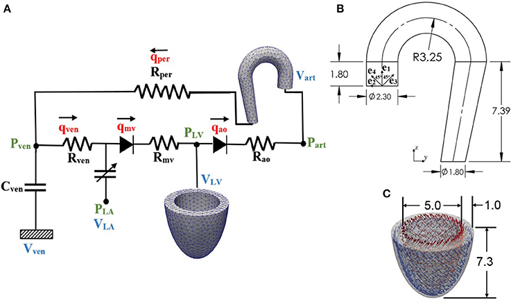
Figure 1. (A) Schematic diagram of the ventricular-arterial modeling framework; the LV and aorta were modeled using FE models, rest of the systemic circulation compartments were modeled using their electrical analog. (B) unloaded aorta geometry with ek (k = 1–4) showing the directions of the four collagen fiber families, (C) unloaded LV geometry with fiber directions varying from 60° at the endocardium to −60° at the epicardium wall (all dimensions are in cm).
Pressure in each storage compartment is a function of its volume. A simplified pressure volume relationship,
was prescribed for the veins, where Vven, 0 is a constant resting volume of the veins and Cven is the total compliance of the venous system. On the other hand, pressure in the left atrium PLA(t) was prescribed to be a function of its volume VLA(t) by the following equations that describe its contraction using a time-varying elastance function e(t):
where
and,
In Equations (5a,b), Ees, LA is the end-systolic elastance of the left atrium, V0, LA is the volume axis intercept of the end-systolic pressure volume relationship (ESPVR), and both ALA and BLA are parameters of the end-diastolic pressure volume relationship (EDPVR) of the left atrium. The driving function e(t) is given in Equation (5c) in which tmax is the point of maximal chamber elastance and τ is the time constant of relaxation. The values of Ees, LA, V0, LA, ALA, BLA, tmax, and τ are listed in Table 1.
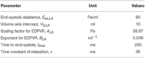
Table 1. Parameters of time varying elastance model for the left atrium.
Finally, pressure in the other two storage compartments, namely, LV and aorta, depends on their corresponding volume through non-closed form functions
The functional relationships between pressure and volume in the LV and aorta were obtained using the FE method as described in the next section.
Finite Element Formulation of the Left Ventricle and Aorta
Finite element formulation of the other two storage compartments can be generalized from the minimization of the following Lagrangian functional with the subscript k = LV denoting the LV and k = art denoting the aorta
In the above equation, uk is the displacement field, Pk, cav is the Lagrange multiplier to constrain the cavity volume Vk, cav(uk) to a prescribed value Vk (Pezzuto and Ambrosi, 2014), pk is a Lagrange multiplier to enforce incompressibility of the tissue (i.e., Jacobian of the deformation gradient tensor Jk = 1), and both c1, k and c2, k are Lagrange multipliers to constrain rigid body translation (i.e., zero mean translation) and rotation (i.e., zero mean rotation) (Pezzuto et al., 2014). The functional relationship between the cavity volumes of the LV and aorta to their respective displacement fields is given by
where Ωinner is the volume enclosed by the inner surface Γinner and the basal surface at z = 0, and nk is the outward unit normal vector.
Pressure-volume relationships of the LV and aorta required in the lumped parameter circulatory model [i.e., Equations (6, 7)] were defined by the solution obtained from minimizing the functional. Taking the first variation of the functional in Equation (8) leads to the following expression:
In Equation (10), Pk is the first Piola Kirchhoff stress tensor, Fk is the deformation gradient tensor, δuk, δpk, δPk, cav, δc1, k, δc2, k are the variation of the displacement field, Lagrange multipliers for enforcing incompressibility and volume constraint, zero mean translation and rotation, respectively. The Euler-Lagrange problem then becomes finding that satisfies
and uk.nk|base = 0 (for constraining the basal deformation to be in-plane) ∀ δuk δ
An explicit time integration scheme was used to solve the ODEs in Equation (1). Specifically, compartment volumes (VLA, VLV, Vart, Vven) at each timestep ti was determined from their respective values and the segmental flow rates (qven, qmv, qao, qper) at previous timestep ti−1 in Equation (1). The computed compartment volumes at ti were used to update the corresponding pressures (PLA, PLV, Part, Pven). Pressures in the left atrium (PLA) and veins (Pven) were computed from Equations (4) and (3), respectively. On the other hand, pressures in the LV (PLV,cav) and aorta (Part, cav) were computed from the FE solutions of Equation (11) (for k = LV and art) with the volumes (VLV, Vart) at timestep ti as input. We note here that (PLV,cav, Part, cav) are scalar Lagrange multipliers in the FE formulation for constraining the cavity volumes to the prescribed values (VLV, Vart). The computed pressures at timestep ti were then used to update the segmental flow rates in Equation (2) that will be used to compute the compartment volumes at timestep ti+1 in the next iteration. Steady-state pressure-volume loop was established by running the simulation over several cardiac cycles, each with a cycle time of 800 ms (equivalent to 75 bpm). All the parameter values used in the circulatory model are listed in Table 2.
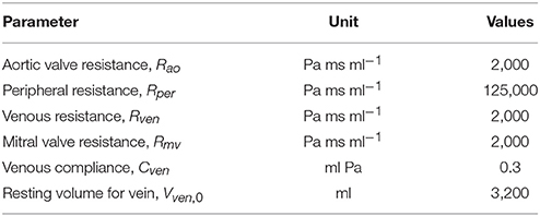
Table 2. Parameters of the closed loop lumped parameter circulatory framework.
Geometry and Microstructure of the LV
The LV geometry was described using a half prolate ellipsoid that was discretized with 1325 quadratic tetrahedral elements. The helix angle associated with the myofiber direction ef0 was varied with a linear transmural variation from 60° at the endocardium to −60° at the epicardium in the LV wall based on previous experimental measurements (Streeter et al., 1969) (Figure 1C).
Constitutive Law of the LV
An active stress formulation was used to describe the LV's mechanical behavior in the cardiac cycle. In this formulation, the stress tensor PLV can be decomposed additively into a passive component PLV,p and an active component PLV,a (i.e., PLV=PLV,a+PLV,p). The passive stress tensor was defined by PLV,p=dWLV/dFLV, where WLV is a strain energy function of a Fung-type transversely-isotropic hyperelastic material (Guccione et al., 1991) given by
where,
In Equation (12), Eij with (i, j) ϵ (f, s, n) are components of the Green-Lagrange strain tensor ELV with f, s, n denoting the myocardial fiber, sheet and sheet normal directions, respectively. Material parameters of the passive constitutive model are denoted by C, bff, bxx, and bfx.
The active stress PLV,a was calculated along the local fiber direction using a previously developed active contraction model (Guccione et al., 1993; Dang et al., 2005),
In the above equation, ef and ef0 are, respectively, the local vectors defining the muscle fiber direction in the current and reference configurations, Tmax is the isometric tension achieved at the longest sarcomere length and Ca0 denotes the peak intracellular calcium concentration. The length dependent calcium sensitivity ECa50 and the variable Ct are given by
In Equation (14a), B is a constant, (Ca0)max is the maximum peak intracellular calcium concentration and l0 is the sarcomere length at which no active tension develops. The variable ω in Equation (14b) is given by
In the above equation, t0 is the time taken to reach peak tension and tr is the duration of relaxation that depends linearly on the sarcomere length l by
where m and b are constants. The sarcomere length l can be calculated from the myofiber stretch λLV by
In Equation (17a), is the right Cauchy-Green deformation tensor and lr is the relaxed sarcomere length. Parameter values associated with the LV model are tabulated in Table 3.
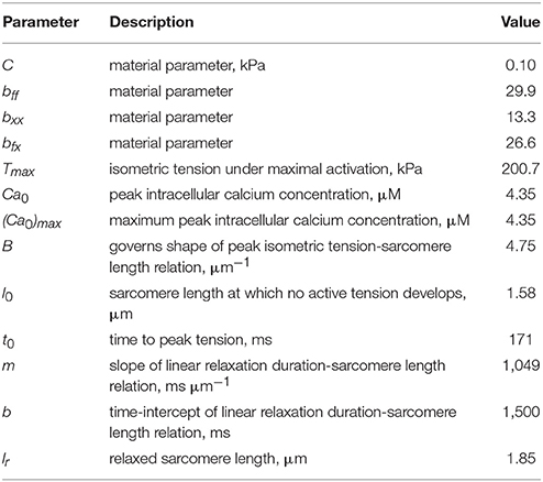
Table 3. Parameters of the LV model.
Geometry and Microstructure of the Aorta
An idealized geometry of the aorta extending from the heart to the thoracic region from a previous study (Vasava et al., 2012) was used here. The geometry was discretized using 1020 quadratic tetrahedral elements. The aorta diameter was assumed to be constant in the first segment starting from the aortic root to the middle of the aortic arch, and then gradually decreased toward the thoracic region. Aortic wall thickness was kept constant (Figure 1B).
Constitutive Law of the Aorta
Stress tensor in the aortic wall was defined by Part=dWart/dFart, where Wart is the sum of the strain energy functions associated with those from the key tissue constituents, namely, elastin-dominated matrix We, collagen fiber families Wc, k and vascular smooth muscle cells (SMC) Wm (Baek et al., 2007; Zeinali-Davarani et al., 2011), i.e.,
Strain energy function of the elastin-dominated amorphous matrix is given by
where Me is the mass per unit volume of the elastin in the tissue, c1 is a material parameter and, is the right Cauchy-Green deformation tensor associated with the aorta.
Four collagen fiber families were considered here. The first and second families of collagen fibers (k = 1 and 2) were oriented in the longitudinal and circumferential directions, whereas the third and fourth families of collagen fibers (k = 3 and 4) were oriented, respectively, at an angle α = 45° and −45° with respect to the longitudinal axis (Figure 1B). We assumed the same strain energy function for all the families of collagen fibers that is given by
In Equation (20), Mk is the mass per unit volume of kth family of collagen fibers, λk is the corresponding stretch of those fibers, and both c2 and c3 are the material parameters. The stretch in the kth family of collagen fibers was defined by where ek0 is the local unit vector defining the corresponding fibers orientation.
Strain energy function of the smooth muscle cells Wm was additively decomposed into one describing its passive mechanical behavior Wm, p and one describing its active behavior Wm, a(i.e., Wm = Wm, p+Wm, a). The passive strain energy function is given by
Here, Mm is the mass per unit volume of the smooth muscle in the tissue, λm is the stretch of the smooth muscle, whereas c4 and c5 are the material parameters. The smooth muscle cells were assumed to be perfectly aligned in the circumferential direction. Its stretch is therefore equivalent to that of the second family of collagen fibers, i.e., λm = λ2. We used the following strain energy function (Zeinali-Davarani et al., 2011) to describe the active tone of vascular smooth muscle,
In Equation (22), Sm is the stress at maximum contraction, ρ is the density of the tissue, λM is the prescribed stretch at which the contraction is maximum and λ0 is the prescribed stretch at which active force generation ceases. Mass per unit volume for the different constituents were calculated using following relations
where ϕe, ϕm, and ϕk denote the mass fraction for elastin, smooth muscle cells and kth family of collagen fibers. It was assumed that 20% of the total collagen mass was distributed equally toward the longitudinal and circumferential fiber families and the remaining 80% was distributed equally to the α = 45° and −45° fiber families. Constitutive parameters, mass fraction of each constituents and other parameters of the aorta model are listed in Table 4.
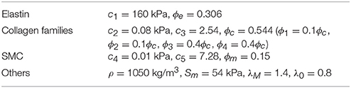
Table 4. Parameters of the aorta model.
The coupled LV-aorta modeling framework, including the solving of FE equations associated with the LV and aorta models, was implemented using the open-source FE library FEniCS (Alnæs et al., 2015).
Results
A baseline case was established using the LV-aorta coupling framework so that LV pressure-volume loop and aorta pressure-diameter curve were consistent with measurements in the normal human systemic circulation under physiological conditions. Specifically, model prediction of the LV ejection fraction (EF) was 56%, which is within the normal range in humans (Figure 2B). Similarly, end-diastolic (ED) and end-systolic (ES) diameters of the aorta in the baseline case (Figure 2C) were comparable to in-vivo measurements (Greenfield and Patel, 1962; Muraru et al., 2014). We note here that diameter of the aorta mentioned in subsequent text refers to its inner diameter. Pressure waveforms of the LV, aorta, and LA (Figure 3) in the baseline case were also within the normal range with an aortic pulse pressure of 50 mmHg (systolic: 128 mmHg, diastolic: 78 mmHg).
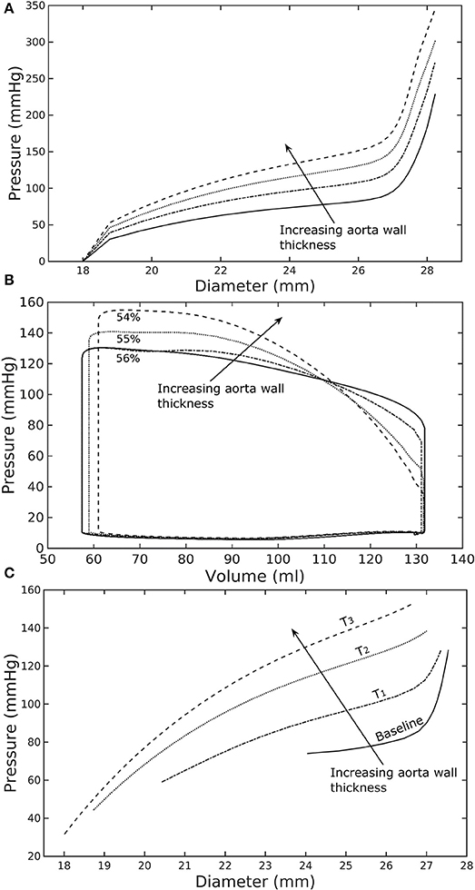
Figure 2. Effects of a change in aorta wall thickness on (A) its ex-vivo pressure–diameter relationship, (B) LV pressure–volume loop and (C) pressure—diameter both operating in-vivo.
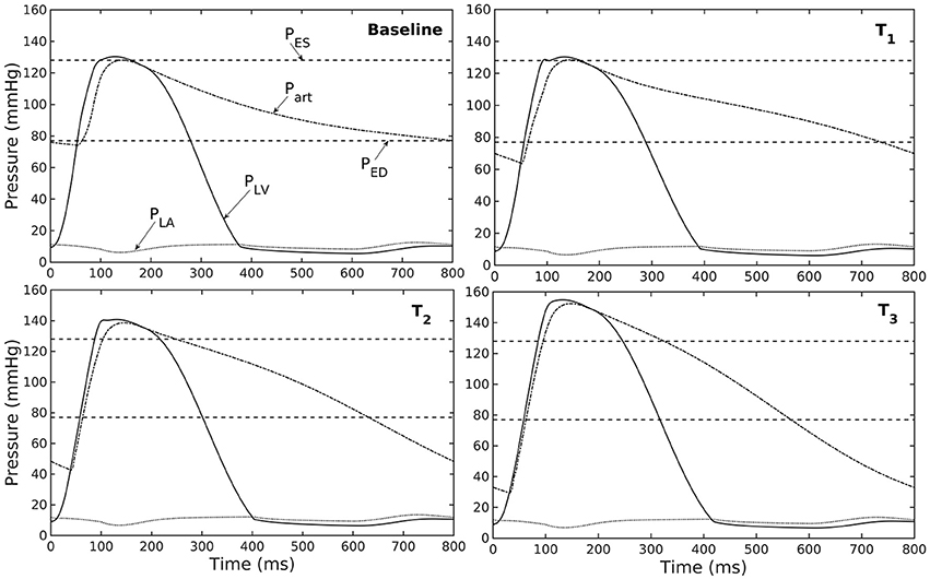
Figure 3. Pressure in LV, aorta, and LA during cardiac cycle with increasing aorta wall thickness in ascending order from the Baseline to T3 case (PES and PED are respectively, the end-systolic and end-diastolic pressure for the baseline case).
Effects of a Change in Aorta Wall Thickness
Varying the wall thickness in the aorta model led to changes in not only the aorta mechanical behavior but also the LV function (Figure 2). The aorta became stiffer (less compliant) with increasing wall thickness as reflected by an increase in the slope of the pressure-diameter curves (Figure 2A). When operating in vivo as simulated in the LV-aorta coupling framework, increasing the aorta wall thickness led to a lower LV EF, a higher peak systolic pressure of the LV (Figure 2B) and a leftward shift in the aorta pressure—diameter relationship with smaller diameter at ED and ES (Figure 2C). Specifically, an increase in aorta ED wall thickness from 1.8 mm (baseline) to 5.4 mm (T3 case) was accompanied by an increase in pulse pressure from 50 mmHg (in the baseline case) to 120 mmHg. In comparison, the mean aortic pressure changed by only about 10 mmHg (decreased from 102 to 93 mm Hg) for the same increase in wall thickness.
Effect of Changes in Mass Fractions of the Aorta Constituents
Similarly, varying mass fraction of the constituents in the aorta wall (see Table 5 for the different cases) also led to changes in both the aorta and LV functions. Increasing collagen mass fraction with a corresponding decrease in SMC and elastin mass fractions (case M1) led to a predominantly exponential pressure - diameter response of the aorta that became extremely steep at larger diameter (i.e., >28 mm) (Figure 4A). This is because the collagen fibers are stiffer than other constituents at large strain. Under in vivo operating condition (as simulated in the LV-aorta coupling framework), an increase in collagen mass fraction resulted in a higher peak systolic pressure and a reduced LV EF (Figure 4B). The exponential mechanical response (shown in Figure 4A) of the aorta with higher collagen mass fraction was also reflected in the ejection phase of the LV pressure-volume loop, where the pressure-volume curve became steeper toward end-of-systole. With a higher collagen mass fraction, the aorta also operated at a larger diameter than the baseline in vivo (Figure 4C). Pulse pressure in the aorta with higher collagen mass fraction was much higher and decayed more rapidly when compared to the baseline case (Figure 5).
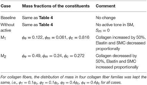
Table 5. Mass fractions of the aorta constituents for different cases investigated in the study.
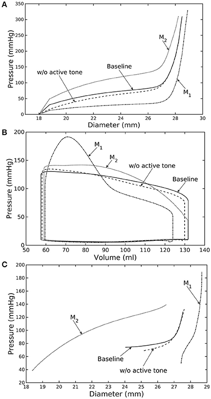
Figure 4. Effects of active tone and aorta constituent mass fractions on (A) its ex-vivo pressure–diameter relationship, (B) LV pressure–volume loop and (C) pressure—diameter both operating in-vivo. (Refer to Table 5 for cases).
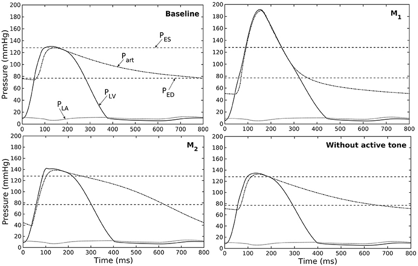
Figure 5. Pressure in LV, aorta, and LA during cardiac cycle for different aorta constituent mass fractions and active tone (PES and PED are respectively, the end-systolic and end-diastolic pressure for the baseline case).
Conversely, reducing collagen mass fraction and increasing elastin and SMC mass fraction proportionally (case M2) led to a dominant neo-Hookean type pressure - diameter behavior, particularly, at smaller diameter (<25 mm). Under in vivo operating condition, the peak pressure increased slightly but EF remained nearly unchanged in the LV (Figure 4B). The aorta also appeared to be more compliant in vivo with a larger change in aortic diameter (~8.1 mm), especially when compared to case M1 that has a higher collagen mass fraction (~1.3 mm) (Figure 4C). On the other hand, the aorta also operated at smaller ED and ES diameters than the baseline. Pressure waveforms of the aorta, LV, and LA were not significantly changed compared to the baseline (Figure 5).
In the absence of SMC's active tone, the aorta became slightly more compliant than the baseline at diameter smaller than 27 mm (Figure 4A). Thus, for a given pressure, the diameter was larger than the baseline. Under in vivo operating condition, this change led to a slight increase in the LV and aorta pressure at ES than the baseline (Figures 4B,C). On the other hand, LV and aorta pressure at ED decreased without the active tone (Figures 4B,C), resulting in an increase in the aortic pulse pressure compared to baseline (Figure 5).
Effects of a Change in LV Contractility
Reducing LV contractility (Tmax) led to a decrease in its peak systolic pressure, end systolic volume and EF (Figure 6A). Pressure also dropped accordingly (Figure 6B) in the aorta together with the peak stress (Figure 6C). With a reduction in LV contractility by 50% (from 200.7 to 100.4 kPa), aorta peak stress was reduced by about 50% compared to the baseline case (from 214 to 110 kPa). The stress was calculated as a root of the sum of the square of all components of the Cauchy stress tensor. Reducing LV contractility also led to changes in the aorta diameter. As a result of lower LV contractility, the aortic pressure decreased that led to less expansion and a decrease in both its ED (from 24.0 mm in baseline to 22.5 mm in case C2) and ES diameter (from 27.5 mm in baseline to 27.0 mm in case C2).
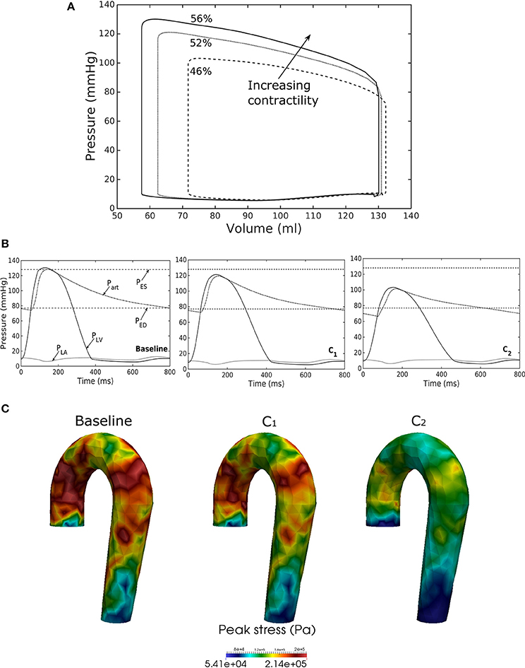
Figure 6. Effects of changes in LV contractility on (A) pressure-volume loop, (B) pressure waveform in LV, aorta, and LA during cardiac cycle, and (C) peak stress in aorta. Contractility decreases in the following order: Baseline, C1, C2.
Effects of a Change in LV Passive Stiffness
Increasing the LV passive stiffness (parameter C) in Equation (12a) led to a stiffer end diastolic pressure—volume relationship that was accompanied by a reduction in preload, peak systolic pressure, and EF (as end systolic volume remained nearly unchanged) in the chamber (Figure 7A). These changes were translated to a decrease in aortic pressure and peak stress (Figures 7B,C) as well as a reduction in its ED (from 24.0 mm in baseline to 22.4 mm in case P2) and ES (from 27.5 mm in baseline to 27.1 mm in case P2) diameters.
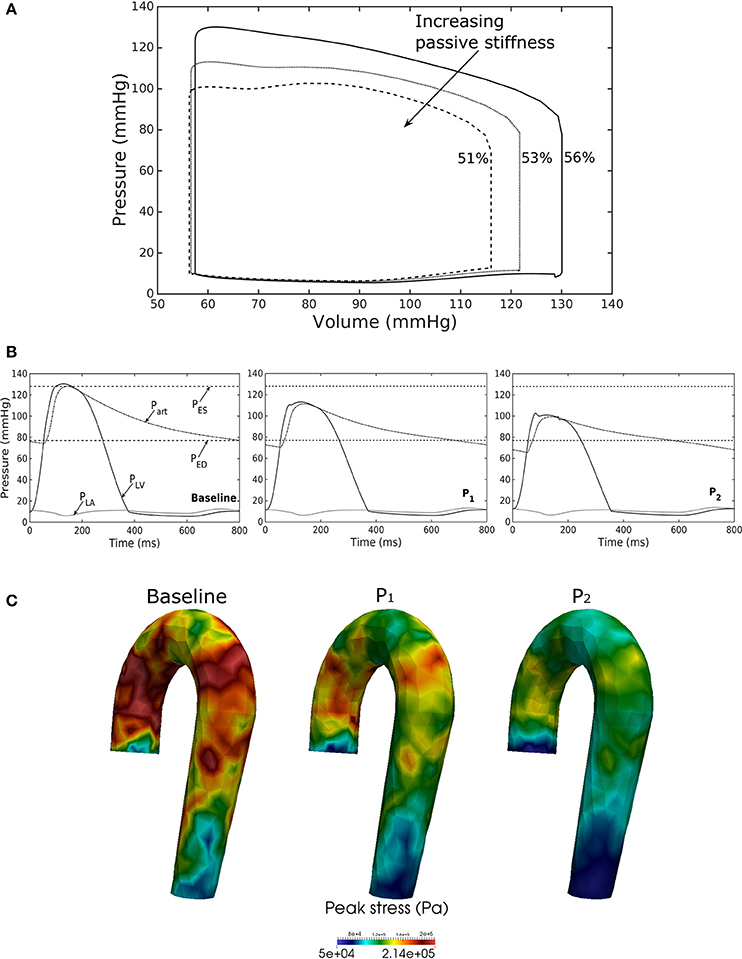
Figure 7. Effects of changes in LV passive stiffness on (A) pressure-volume loop, (B) pressure waveform in LV, aorta, and LA during cardiac cycle, and (C) peak stress in aorta. Passive stiffness increases in the following order: Baseline, P1, P2.
Discussion
Finite element models of the LV have been widely used in the literature to study its mechanics as well as organ-scale physiological behaviors in the cardiac cycle (Usyk et al., 2002; Kerckhoffs et al., 2007; Lee et al., 2016; Xi et al., 2016; Shavik et al., 2017). In these models, the aorta is usually represented within the lumped parameter circulatory model by its electrical analog, which cannot separate the effects its geometry, microstructure, and constituents' mechanical behavior have on the LV's operating behavior in vivo and vice versa. To the best of our knowledge, this is the first computational modeling framework in which FE models of the aorta and LV are coupled in a closed-loop fashion. This framework enables us to take into detailed account of the geometrical, microstructural, and mechanical behavior of the LV and aorta. We have shown here that the coupled LV—aorta FE framework is able to capture physiological behaviors in both the LV and aorta that are consistent with in vivo measurements. We also showed that the framework can reasonably predict the effects of changes in geometry and microstructural details the two compartments have on each other over the cardiac cycle.
Using a detailed FE model of the aorta has enabled us to separate the contributions of the key load bearing constituents (elastin, collagen fibers, and SMCs) have on its mechanical behavior. The aorta FE model predicted a pressure—diameter response in which the mechanical behavior of each constituent is clearly detectable (Figure 2A). For instance, mechanical behavior of aorta at lower diameter range (low stretch) is relatively compliant as it is largely endowed by elastin, but exhibits a very stiff behavior at the higher diameter range (high stretch) when more collagen fibers are recruited. The behavior is consistent with previous experimental studies (Roach and Burton, 1957; Schriefl et al., 2012; Kohn et al., 2015). The pressure—diameter relationship predicted by our model (Figure 2A) resembled a S-shaped curve with a very stiff response after the inflection point that is a typical feature of large proximal arterial vessels (Bader, 1967; Towfiq et al., 1986).
Our model predicted that an increase in aortic wall thickness led it to become more constricted with smaller ED and ES diameter under in vivo operating conditions when coupled to the LV in our modeling framework (Figure 2C). Systolic blood pressure and pulse pressure in the aorta increased as a result, and was accompanied by a reduction in stroke volume and an increase in LV peak systolic pressure (Figure 2B). Although previous vascular studies suggest that an increase in arterial wall thickness (that may be accompanied by an increase in stiffness) is a result from an increase blood pressure during aging, more recent evidence have suggested that stiffening is a cause for the increase in blood pressure in which a positive feedback loop between them proceeds gradually (Humphrey et al., 2016). These features are consistent with those found in clinical and experimental studies. Specifically, it has been found that the mean aortic wall thickness increases with age (Li et al., 2004; Rosero et al., 2011) in human, which increases the risk of hypertension and atherosclerosis. Similarly, our model predicted that an increase in aortic wall thickness by 70% elevates the aortic pressure over the hypertensive range (>140 mmHg) (Figure 3).
Changes in the aorta microstructure is a feature of pathological remodeling as well as aging. In the systemic vasculature, the proximal aorta has a compliant behavior that helps to keep the systolic blood pressure down. With aging, however, elastin degenerates and is replaced (i.e., compensated) by collagen in the aorta wall (Schlatmann and Becker, 1977; Tsamis et al., 2013; Kohn et al., 2015). Consequently, the collagen fibers bear more of the load that substantially increases the aorta wall stiffness, especially at high stretch. A stiffer aorta leads to many adverse effects including elevated systolic and pulse pressure during ejection, faster decay in the aortic pressure waveform during diastole, and an increase in ventricular afterload that reduces the LV EF (Borlaug and Kass, 2011). These behaviors are all captured in our framework when collagen and elastin mass fractions were increased and decreased, respectively. Specifically, these microstructural changes led to a reduction in EF (Figure 4B) and an increase in the aortic systolic and pulse pressure with a faster decay of aortic pressure waveform (Figure 5). Our framework also predicted that the aorta underwent more expansion in vivo and have a larger operating diameter when collagen mass fraction increases (Figure 4C), which is another key characteristic of aging (Bader, 1967; Mao et al., 2008; Craiem et al., 2012). Interestingly, changes in the aorta collagen mass fraction (that lead to it stiffen at high stretch) also affects the shape of the LV pressure volume loop (Figure 4B, case M1). Specifically, a rapid steepening of the LV pressure-volume curve near end-of-systole is predicted by our model when collagen mass fraction is increased. This result suggests that the shape of the LV pressure-volume loop may also reflect, to some extent, the accumulation of collagen fibers in the aorta during remodeling.
Our framework also predicted how changes in the contractility and passive stiffness of the LV affects the aorta function. A decrease in LV contractility led to lower LV EF, lower aortic systolic and pulse pressures, as well as a reduction in the aorta peak stress during the cardiac cycle (Figure 6). A change in contractility (or inotropic state of the myocardium) produced expected changes (Katz, 1988; Burkhoff, 2005) in the LV pressure—volume loop and aortic pulse pressure. Similarly, the model predicted results from a change in the LV passive stiffness that are consistent with experimental observations (Figure 7). With increasing passive stiffness, LV EF decreases and is accompanied by a corresponding decrease in aortic systolic and pulse pressure, as well as peak stress. A change in the passive stiffness of LV (due to such as an alteration in lusitropy), also shows similar changes in the LV pressure—volume loops (Katz, 1988; Burkhoff, 2005) as well as the aortic pressure.
Most clinical studies focus either on the behavior of the LV or aorta. While a number of studies have investigated ventricular—arterial coupling (Kawaguchi et al., 2003; Borlaug and Kass, 2011; Antonini-Canterin et al., 2013; Ky et al., 2013), simplified indices (such as the ratio of end-systolic volume to stroke volume) were used in them to describe this coupling. It is, however, impossible to separate the contribution of microstructure, mechanical behavior, and geometry of the aorta (e.g., diameter or thickness) and LV to any changes in ventricular—arterial coupling. The framework described here helps overcome this limitation and may be useful for developing more insights of the ventricular—arterial interaction. This framework will be extended in future to include the pulmonary vasculature for a more complete understanding of the interactions between the heart and vasculature under different physiological or pathological conditions.
Model Limitations
We have shown that our coupled LV-aorta FE modeling framework is capable of predicting behaviors that are consistent with measurements. There are, however, some limitations associated with our model. First, idealized geometries were used to represent the aorta and LV models. The idealized half-prolate geometry of the LV used here neglected any asymmetrical geometrical features while the aorta geometry was also simplified and had uniform wall thickness. Because wall thickness decreases slightly along the aorta (Mello et al., 2004), its displacement with the given material parameters may be under-estimated. Second, we have assumed homogeneous material properties in our models. Given that studies have suggested that the mechanical properties may be inhomogeneous in the aorta (Kermani et al., 2017) and LV (Khokhlova and Iribe, 2016), the prescribed material parameters are bulk quantities. While thoracic aortic wall thickness and its stiffness varies, previous experimental studies reported that the aortic structural stiffness (product of intrinsic stiffness and aortic wall thickness) is relatively uniform in the circumferential and longitudinal directions (Kim and Baek, 2011; Kim et al., 2013). Third, the dynamical behavior of fluid and its interaction with the vessel wall were neglected here, and as such, the framework did not take into account the spatial variation of pressure waveform along the aortic tree and shear stress on the luminal surface of the vessel. However, we do not expect this limitation to severely affect our result because wall shear stress in the human aorta (~50 dyn/cm2 or 0.037 mmHg) (LaDisa et al., 2011) is substantially lower than the pressure (normal stress) (60–120 mm Hg), and the arterial pressure increases by only about 10% from the ascending to the abdominal aorta (Smulyan and Safar, 1997). Fourth, a rule based myofiber orientation in which the helix angle varies linearly across the myocardial wall was used to describe the LV microstructure. Fifth, remodeling of the aorta and LV was simulated by directly manipulating the parameters without consideration of any growth and remodeling mechanisms. Last, we have considered only systemic circulation in this model and ignored the presence of the right ventricle and pulmonary circulatory system that may affect LV and aorta mechanics.
Author Contributions
SMS and LCL developed the theoretical formulation and computational framework of the model. ZJ and SB helped on the development of the theoretical formulation. SMS carried out the simulations for different cases and prepared the results. All authors helped in interpretation of the results and contributed to the final manuscript.
Funding
This work was supported by American Heart Association (AHA) grant 17SDG33370110 (LCL), NIH R01 HL134841 (LCL), and NIH U01 1HL135842 grant (SB and LCL).
Conflict of Interest Statement
The authors declare that the research was conducted in the absence of any commercial or financial relationships that could be construed as a potential conflict of interest.
References
Alnæs, M., Blechta, J., Hake, J., Johansson, A., Kehlet, B., Logg, A., et al. (2015). The FEniCS project version 1.5. Arch. Numer. Softw. 3, 9–23. doi: 10.11588/ans.2015.100.20553
Antonini-Canterin, F., Poli, S., Vriz, O., Pavan, D., Bello, V. D., and Nicolosi, G. L. (2013). The ventricular-arterial coupling: from basic pathophysiology to clinical application in the echocardiography laboratory. J. Cardiovasc. Echography 23:91. doi: 10.4103/2211-4122.127408
Arts, T., Delhaas, T., Bovendeerd, P., Verbeek, X., and Prinzen, F. (2005). Adaptation to mechanical load determines shape and properties of heart and circulation: the circadapt model. Am. J. Physiol. Heart Circ. Physiol. 288, 1943–1954. doi: 10.1152/ajpheart.00444.2004
Bader, H. (1967). Dependence of wall stress in the human thoracic aorta on age and pressure. Circ. Res. 20, 354–361.
Baek, S., Valentín, A., and Humphrey, J. D. (2007). Biochemomechanics of cerebral vasospasm and its resolution: iconstitutive relations, i., and model simulations. Ann. Biomed. Eng. 35, 1498–1509. doi: 10.1007/s10439-007-9322-x
Borlaug, B. A., and Kass, D. A. (2011). Ventricular-vascular interaction in heart failure. Cardiol. Clin. 29, 447–459. doi: 10.1016/j.ccl.2011.06.004
Burkhoff, D. (2005). Assessment of systolic and diastolic ventricular properties via pressure-volume analysis: a guide for clinical, translational, and basic researchers. Am. J. Physiol. Heart Circ. Physiol. 289, H501–H512. doi: 10.1152/ajpheart.00138.2005
Craiem, D., Casciaro, M. E., Graf, S., Chironi, G., Simon, A., and Armentano, R. L. (2012). Effects of aging on thoracic aorta size and shape: a non-contrast ct study. Conf. Proc. IEEE. Eng. Med. Biol. Soc. 2012, 4986–4989. doi: 10.1109/EMBC.2012.6347112
Dang, A. B., Guccione, J. M., Mishell, J. M., Zhang, P., Wallace, A. W., Gorman, R. C., et al. (2005). Akinetic myocardial infarcts must contain contracting myocytes: finite-element model study. Am. J. Physiol. Heart Circ. Physiol. 288, H1844–H1850. doi: 10.1152/ajpheart.00961.2003
Gao, H., Wang, H., Berry, C., Luo, X., and Griffith, B. E. (2014). Quasi-Static image-based immersed boundary-finite element model of left ventricle under diastolic loading. Int. J. Numer. Method. Biomed. Eng. 30, 1199–1222. doi: 10.1002/cnm.2652
Genet, M., Lee, L. C., Nguyen, R., Haraldsson, H., Acevedo-Bolton, G., Zhang, Z., et al. (2014). Distribution of normal human left ventricular myofiber stress at end diastole and end systole: a target for in silico design of heart failure treatments. J. Appl. Physiol. 117, 142–152. doi: 10.1152/japplphysiol.00255.2014
Giamouzis, G., Schelbert, E. B., and Butler, J. (2016). Growing evidence linking microvascular dysfunction with heart failure with preserved ejection fraction. J. Am. Heart Assoc. 5:e003259. doi: 10.1161/JAHA.116.003259
Greenfield, J. C., and Patel, D. J. (1962). Relation between pressure and diameter in the ascending aorta of man. Circ. Res. 10, 778–781. doi: 10.1161/01.RES.10.5.778
Guccione, J. M., McCulloch, A. D., and Waldman, L. K. (1991). Passive material properties of intact ventricular myocardium determined from a cylindrical model. J. Biomech. Eng. 113, 42–55. doi: 10.1115/1.2894084
Guccione, J. M., Waldman, L. K., and McCulloch, A. D. (1993). Mechanics of active contraction in cardiac muscle: part ii–cylindrical models of the systolic left ventricle. J. Biomech. Eng. 115, 82–90. doi: 10.1115/1.2895474
Hill, M. R., Simon, M. A., Valdez-Jasso, D., Zhang, W., Champion, H. C., and Sacks, M. S. (2014). Structural and mechanical adaptations of right ventricle free wall myocardium to pressure overload. Ann. Biomed. Eng. 42, 2451–2465. doi: 10.1007/s10439-014-1096-3
Hsu, M. C., and Bazilevs, Y. (2011). Blood vessel tissue prestress modeling for vascular fluidstructure interaction simulation. Finite Elem. Anal. Design 47, 593–599. doi: 10.1016/j.finel.2010.12.015
Humphrey, J. D., Harrioson, D. G., Figueroa, C. A., Lacolley, P., and Laurent, S. (2016). Central artery stiffness in hypertension and aging: a problem with cause and consequence. Circ. Res. 118, 379–381. doi: 10.1161/CIRCRESAHA.115.307722
Katz, A. M. (1988). Influence of altered inotropy and lusitropy on ventricular pressure-volume loops. J. Am. Coll. Cardiol. 11, 438–445. doi: 10.1016/0735-1097(88)90113-1
Kawaguchi, M., Hay, I., Fetics, B., and Kass, D. A. (2003). Combined ventricular systolic and arterial stiffening in patients with heart failure and preserved ejection fraction: implications for systolic and diastolic reserve limitations. Circulation 107, 714–720. doi: 10.1161/01.CIR.0000048123.22359.A0
Kerckhoffs, R. C. P., Neal, M. L., Gu, Q., Bassingthwaighte, J. B., Omens, J. H., and McCulloch, A. D. (2007). Coupling of a 3D finite element model of cardiac ventricular mechanics to lumped systems models of the systemic and pulmonic circulation. Ann. Biomed. Eng. 35, 1–18. doi: 10.1007/s10439-006-9212-7
Kermani, G., Hemmasizadeh, A., Assari, S., Autieri, M., and Darvish, K. (2017). Investigation of inhomogeneous and anisotropic material behavior of porcine thoracic aorta using nano-indentation tests. J. Mech. Behav. Biomed. Mater. 69, 50–56. doi: 10.1016/j.jmbbm.2016.12.022
Khokhlova, A. D., and Iribe, G. (2016). Transmural differences in mechanical properties of isolated subendocardial and subepicardial cardiomyocytes. Bull. Exp. Biol. Med. 162, 48–50. doi: 10.1007/s10517-016-3542-8
Kim, H. J., Vignon-Clementel, I. E., Figueroa, C. A., Ladisa, J. F., Jansen, K. E., Feinstein, J. A., et al. (2009). On coupling a lumped parameter heart model and a three-dimensional finite element aorta model. Ann. Biomed. Eng. 37, 2153–2169. doi: 10.1007/s10439-009-9760-8
Kim, J., Hong, J. W., and Baek, S. (2013). Longitudinal differences in the mechanical properties of the thoracic aorta depend on circumferential regions. J. Biomed. Mater. Res. A 101, 1525–1529. doi: 10.1002/jbm.a.34445
Kim, J., and Baek, S. (2011). Circumferential variations of mechanical behavior of the porcine thoracic aorta during the inflation test. J. Biomech. 44, 1941–1947. doi: 10.1016/j.jbiomech.2011.04.022
Kohn, J. C., Lampi, M. C., and Reinhart-King, C. A. (2015). Age-related vascular stiffening: causes and consequences. Front. Genet. 6:112. doi: 10.3389/fgene.2015.00112
Ky, B., French, B., Khan, A. M., Plappert, T., Wang, A., Chirinos, J. A., et al. (2013). ventricular-arterial coupling, remodeling, and prognosis in chronic heart failure. J. Am. Coll. Cardiol. 62, 1165–1172. doi: 10.1016/j.jacc.2013.03.085
LaDisa, J. F., Dholakia, R. J., Figueroa, C. A., Vignon-Clementel, I. E., Chan, F. P., Samyn, M. M., et al. (2011). Computational simulations demonstrate altered wall shear stress in aortic coarctation patients treated by resection with end-to-end anastomosis. Congenit. Heart Dis. 6, 432–443. doi: 10.1111/j.1747-0803.2011.00553.x
Lau, K. D., and Figueroa, C. A. (2015). simulation of short-term pressure regulation during the tilt test in a coupled 3D−0D closed-loop model of the circulation. Biomech. Model. Mechanobiol. 14, 915–929. doi: 10.1007/s10237-014-0645-x
Lee, L. C., Wenk, J. F., Zhong, L., Klepach, D., Zhang, Z., Ge, L., et al. (2013). analysis of patient-specific surgical ventricular restoration: importance of an ellipsoidal left ventricular geometry for diastolic and systolic function. J. Appl. Physiol. 115, 136–144. doi: 10.1152/japplphysiol.00662.2012
Lee, L. C., Sundnes, J., Genet, M., Wenk, J. F., and Wall, S. T. (2016). An integrated electromechanical-growth heart model for simulating cardiac therapies. Biomech. Model. Mechanobiol. 15, 791–803. doi: 10.1007/s10237-015-0723-8
Li, A. E., Kamel, I., Rando, F., Anderson, M., Kumbasar, B., Lima, J. A. C., et al. (2004). Using MRI to assess aortic wall thickness in the multiethnic study of atherosclerosis: distribution by race, sex, and age. Am. J. Roentgenol. 182, 593–597. doi: 10.2214/ajr.182.3.1820593
Mao, S. S., Ahmadi, N., Shah, B., Beckmann, D., Chen, A., Ngo, L., et al. (2008). Normal thoracic aorta diameter on cardiac computed tomography in healthy asymptomatic adults. Acad. Radiol. 15, 827–834. doi: 10.1016/j.acra.2008.02.001
Mello, J. M., de Orsi, A. M., and Padovani, C. R. (2004). Structure of the aortic wall in the guinea pig and rat. Braz. J. Morphol. 21, 35–38.
Muraru, D., Maffessanti, F., Kocabay, G., Peluso, D., Dal Bianco, L., Piasentini, E., et al. (2014). Ascending aorta diameters measured by echocardiography using both leading edge-to-leading edge and inner edge-to-inner edge conventions in healthy volunteers. Eur. Heart J. Cardiovasc. Imaging 15, 415–422. doi: 10.1093/ehjci/jet173
Naeije, R., and Manes, A. (2014). The right ventricle in pulmonary arterial hypertension. Eur. Respir. Rev. 23, 476–487. doi: 10.1183/09059180.00007414
Pezzuto, S., and Ambrosi, D. (2014). Active contraction of the cardiac ventricle and distortion of the microstructural architecture. Int. J. Numer. Method. Biomed. Eng. 30, 1578–1596. doi: 10.1002/cnm.2690
Pezzuto, S., Ambrosi, D., and Quarteroni, A. (2014). An orthotropic active-strain model for the myocardium mechanics and its numerical approximation. Eur. J. Mech. A Solids 48, 83–96. doi: 10.1016/j.euromechsol.2014.03.006
Rain, S., Handoko, M. L., Trip, P., Gan, C. T., Westerhof, N., Stienen, G. J., et al. (2013). Right ventricular diastolic impairment in patients with pulmonary arterial hypertension. Circulation 128, 2016–2025, 1–10. doi: 10.1161/CIRCULATIONAHA.113.001873
Roach, M. R., and Burton, A. C. (1957). The reason for the shape of the distensibility curves of arteries. Can. J. Biochem. Physiol. 3568, 1–90. doi: 10.1139/o57-080
Rosero, E. B., Peshock, R. M., Khera, A., Clagett, P., Lo, H., and Timaran, C. H. (2011). Sex, race, and age distributions of mean aortic wall thickness in a multiethnic population-based sample. J. Vasc. Surg. 53, 950–957. doi: 10.1016/j.jvs.2010.10.073
Schlatmann, T. J.M., and Becker, A. E. (1977). Histologic changes in the normal aging aorta: implications for dissecting aortic aneurysm. Am. J. Cardiol. 39, 13–20. doi: 10.1016/S0002-9149(77)80004-0
Schriefl, A. J., Zeindlinger, G., Pierce, D. M., Regitnig, P., and Holzapfel, G. A. (2012). Determination of the layer-specific distributed collagen fibre orientations in human thoracic and abdominal aortas and common iliac arteries. J. R. Soc. Interface 9, 1275–1286. doi: 10.1098/rsif.2011.0727
Shavik, S. M., Wall, S. T., Sundnes, J., Burkhoff, D., and Lee, L. C. (2017). Organ-level validation of a cross-bridge cycling descriptor in a left ventricular finite element model: effects of ventricular loading on myocardial strains. Physiol. Rep. 5:e13392. doi: 10.14814/phy2.13392
Shimoda, L. A., and Laurie, S. S. (2013). Vascular remodeling in pulmonary hypertension. J. Mol. Med. 91, 297–309. doi: 10.1007/s00109-013-0998-0
Smith, B. W., Chase, J. G., Nokes, R. I., Shaw, G. M., and Wake, G. (2004). Minimal haemodynamic system model including ventricular interaction and valve dynamics. Med. Eng. Phys. 26, 131–139. doi: 10.1016/j.medengphy.2003.10.001
Smulyan, H., and Safar, M. E. (1997). Systolic blood pressure revisited. J. Am. Col. Cardiol. 29, 1407–1413. doi: 10.1016/S0735-1097(97)00081-8
Streeter, D. D., Spotnitz, H. M., Patel, D. P., Ross, J., and Sonnenblick, E. H. (1969). Fiber orientation in the canine left ventricle during diastole and systole. Circ. Res. 24, 339–347. doi: 10.1161/01.RES.24.3.339
Su, M. Y., Lin, L. Y., Tseng, Y. H., Chang, C. C., Wu, C. K., Lin, J. L., et al. (2014). CMR-verified diffuse myocardial fibrosis is associated with diastolic dysfunction in HFpEF. JACC Cardiovasc. Imaging 7, 991–997. doi: 10.1016/j.jcmg.2014.04.022
Towfiq, B. A., Weir, J., and Rawles, J. M. (1986). Effect of age and blood pressure on aortic size and stroke distance. Br. Heart J. 55, 560–568. doi: 10.1136/hrt.55.6.560
Trayanova, N. A., Constantino, J., and Gurev, V. (2011). Electromechanical models of the ventricles. Am. J. Physiol. Heart Circ. Physiol. 301, H279–H286. doi: 10.1152/ajpheart.00324.2011
Tsamis, A., Krawiec, J. T., and Vorp, D. A. (2013). Elastin and collagen fibre microstructure of the human aorta in ageing and disease: a review. J. R. Soc. Interface 10:20121004 doi: 10.1098/rsif.2012.1004
Usyk, T. P., LeGrice, I. J., and McCulloch, A. D. (2002). Computational model of three-dimensional cardiac electromechanics. Comput. Vis. Sci. 4, 249–257. doi: 10.1007/s00791-002-0081-9
Vasava, P., Jalali, P., Dabagh, M., and Kolari, P. J. (2012). Finite element modelling of pulsatile blood flow in idealized model of human aortic arch: study of hypotension and hypertension. Comput. Math. Methods Med. 2012:861837. doi: 10.1155/2012/861837
Wall, S. T., Guccione, J. M., Ratcliffe, M. B., and Sundnes, J. S. (2012). Electromechanical feedback with reduced cellular connectivity alters electrical activity in an infarct injured left ventricle: a finite element model study. Am. J. Physiol. Heart. Circ. Physiol. 302, H206–H214. doi: 10.1152/ajpheart.00272.2011
Wenk, J. F., Sun, K., Zhang, Z., Soleimani, M., Ge, L., Saloner, D., et al. (2011). Regional left ventricular myocardial contractility and stress in a finite element model of posterobasal myocardial infarction. J. Biomech. Eng. 133:44501. doi: 10.1115/1.4003438
Xi, C., Latnie, C., Zhao, X., Tan, J. L., Wall, S. T., Genet, M., et al. (2016). Patient-specific computational analysis of ventricular mechanics in pulmonary arterial hypertension. J. Biomech. Eng. 138:111001. doi: 10.1115/1.4034559
Keywords: left ventricle, finite element modeling, ventricular-arterial coupling, arterial mechanics, cardiac mechanics, systemic circulation
Citation: Shavik SM, Jiang Z, Baek S and Lee LC (2018) High Spatial Resolution Multi-Organ Finite Element Modeling of Ventricular-Arterial Coupling. Front. Physiol. 9:119. doi: 10.3389/fphys.2018.00119
Received: 25 November 2017; Accepted: 05 February 2018;
Published: 02 March 2018.
Edited by:
Timothy W. Secomb, University of Arizona, United StatesReviewed by:
Jacopo Biasetti, Johns Hopkins University, United StatesVicky Yang Wang, University of Auckland, New Zealand
Copyright © 2018 Shavik, Jiang, Baek and Lee. This is an open-access article distributed under the terms of the Creative Commons Attribution License (CC BY). The use, distribution or reproduction in other forums is permitted, provided the original author(s) and the copyright owner are credited and that the original publication in this journal is cited, in accordance with accepted academic practice. No use, distribution or reproduction is permitted which does not comply with these terms.
*Correspondence: Lik Chuan Lee, lclee@egr.msu.edu