Monitoring beam charge during FLASH irradiations
 Borivoj Vojnovic
 Iain D. C. Tullis
 Robert G. Newman1
  Kristoffer Petersson
- 1Department of Oncology, Oxford Institute for Radiation Oncology, University of Oxford, Oxford, United Kingdom
- 2Department of Haematology, Oncology, and Radiation Physics, Skåne University Hospital, Lund University, Lund, Sweden
In recent years, FLASH irradiation has attracted significant interest in radiation research. Studies have shown that irradiation at ultra-high dose rates (FLASH) reduces the severity of toxicities in normal tissues compared to irradiation at conventional dose rates (CONV), as currently used in clinical practice. Most pre-clinical work is currently carried out using charged particle beams and the beam charge monitor described here is relevant to such beams. Any biological effect comparisons between FLASH and CONV irradiations rely on measurement of tissue dose. While well-established approaches can be used to monitor, in real time, the dose delivered during CONV irradiations, monitoring FLASH doses is not so straightforward. Recently the use of non-intercepting beam current transformers (BCTs) has been proposed for FLASH work. Such BCTs have been used for decades in numerous accelerator installations to monitor temporal and intensity beam profiles. In order to serve as monitoring dosimeters, the BCT output current must be integrated, using electronic circuitry or using software integration following signal digitisation. While sensitive enough for FLASH irradiation, where few intense pulses deliver the requisite dose, the inherent insensitivity of BCTs and the need for a wide detection bandwidth makes them less suitable for use during CONV “reference” irradiations. The purpose of this article is to remind the FLASH community of a different mode of BCT operation: direct monitoring of charge, rather than current, achieved by loading the BCT capacitively rather than resistively. The resulting resonant operation achieves very high sensitivities, enabling straightforward monitoring of output during both CONV and FLASH regimes. Historically, such inductive charge monitors have been used for single pulse work; however, a straightforward circuit modification allows selective resonance damping when repetitive pulsing is used, as during FLASH and CONV irradiations. Practical means of achieving this are presented, as are construction and signal processing details. Finally, results are presented showing the beneficial behaviour of the BCT versus an (Advanced Markus) ionisation chamber for measurements over a dose rate range, from <0.1 Gys−1 to >3 kGys−1.
1 Introduction
The study of ultra-high dose rate (FLASH) irradiation using charged particle beams has attracted significant recent interest. A number of studies have demonstrated that FLASH irradiation reduces the severity of toxicities in normal tissues compared to irradiation at conventional dose rates (CONV), as currently used in clinical practice [1–8]. The mechanism responsible for reduced tissue toxicity following FLASH radiotherapy has not yet been elucidated and it is likely that both basic and pre-clinical work will proceed for some time to come. Understanding the FLASH effect in multiple tissue sites and species will be essential before widely applying the technique in clinical studies [9–15].
One of the major factors limiting the preclinical use of FLASH RT is the difficulty in obtaining accurate dosimetry and in measuring FLASH irradiation parameters (such as dose, mean and instantaneous dose rate, dose per pulse, etc.) using well-established, conventional radiation detectors [16, 17]. The ability to monitor and control the output of radiation source during both FLASH and reference CONV scenarios is particularly desirable. Commonly, radiation must be monitored in real time. For CONV irradiations, transmission ionisation chambers in the head of an electron linear accelerator or within the output beam lines of a charged ion installation can be used. The transmission chambers can be used to monitor dose, dose rate, beam flatness, beam symmetry, and so on, in real time as the beam traverses the chamber. In the case of FLASH irradiations, the accuracy of transmission ionisation chambers suffers because of saturation effects caused by the high dose per pulse conditions present during FLASH18. Several publications have noted the difficulties associated with accurate dosimetry [18, 19] when dose rates in the range of 30 Gy s−1 to several MGy s−1, delivered in multiple or single pulses are to be monitored. Ion recombination and other effects in ionisation chambers will preclude their use at these high dose rates [20–24] unless they are operated at very high bias voltages and appropriate corrections are applied. Hence, off-line dosimeters like alanine and radio-chromic film are the preferred dosimeters [25–27]; other approaches are reviewed by [28]. To date, most preclinical work has been performed using electron beams generated by linear accelerators (linacs) of energies 4–20 MeV [29–31]. The use of protons for FLASH irradiation, or other hadron beams [32, 33] has also been investigated and it may be possible to adapt the approach described here to such studies.
Maximising the output beam current is usually required for FLASH work, and the extent to which this can be achieved in a given linac design, assuming that beam current is available from the gun, is determined by the available radio frequency (RF) power and other accelerator design parameters, such as the shunt resistance and quality factor of the accelerating waveguide. Typical peak beam currents of 10 mA to 1 A, over pulse widths ranging from 1–4 μs are used for FLASH work, at repetition rates of several hundred macro-pulses per second. CONV irradiations are often performed at similar or lower repetitions rates (10–200 Hz) and lower peak beam currents, or performed with shorter-lasting macro-pulses. In addition to the need to perform dosimetry, it is often useful to be able to return to specific previously used beam characteristics and to have the ability to check performance: an on-line beam charge monitor is thus essential, providing the ability to monitor each output macro-pulse during the irradiation sequence. Indeed, for clinical applications, such monitors are mandatory [34].
2 Materials and methods
2.1 Non-intercepting beam charge monitoring
Beam current transformers (BCTs) are non-intercepting, inductive current monitors that have shown promise for real-time monitoring of electron FLASH beams [35, 36]. These devices are toroidal inductive sensors where the moving electron charge forms a primary turn that induces a voltage in the secondary toroidal winding. BCTs are based on well-established current transformer design approaches [37] that can be used even at picosecond times [38]. They offer unique advantages whenever time-varying electrical currents (in conductors or in beams) are to be measured. No direct connection to the measured circuit is necessary, ensuring isolation and relative freedom from spurious ground currents.
For a given irradiation geometry and with a given beam energy, measurement of beam charge has been found by others to correlate well with delivered dose [35, 36], as would be expected. We have successfully used, for many years, inductive non-intercepting charge monitoring as a surrogate indicator of dose. It is noted that such monitors are only able to measure the charge pulses leaving the accelerator and not charge pulses impinging on the tissue or target of interest. Such devices must thus be independently calibrated in order to provide a (surrogate) dose readout, and re-calibrated when the working distance is changed [39, 40], or beam scattering [41–43] introduced.
Wide bandwidths (typically 5–20 MHz) are required to monitor microsecond wide pulses that are usually associated with rise/fall times of tens to hundreds of nanoseconds. Means of constructing and analysing such devices have been described [44, 45], where resonances in the secondary winding due to capacitance between the core winding and electrical shields are appropriately damped.
The electron beam can be assumed to be a current filament moving through the axis of a toroidally wound coil of
where
For a pulsed electron linear accelerator in the mega-electron voltage (MeV) range, the voltage induced at the output of a BCT can be readily approximated as a function of the electron density of the pulse and the cross-sectional area of the BCT [46]. Using BCTs to measure the output of FLASH beams is useful because the beam(s) can be monitored in real time with negligible perturbation and, just as importantly, without saturation effects [35]. However, because of the necessary load resistance must have a low value in order to achieve a suitably low minimum frequency, their sensitivity, for CONV beams in particular, can be limiting. This does not imply that BCTs cannot be used to monitor CONV irradiations, but the signal levels are low and electrical interference from the accelerator and from other sources make their design and implementation challenging.
However, such transformers can be made to operate in a distinctly different manner that permits direct integration of the current pulse; these devices will be termed Beam Current Integrating Transformers (BCITs). A readout of the integrated pulse current is preferred when a readout proportional to beam charge is required. The charge per pulse is proportional to dose delivered by the beam and dose monitoring is of interest during FLASH and CONV irradiations. This integrating mode is achieved by simply loading the secondary coil capacitively and by using a high load resistance: assuming negligible core and loading losses, a resonant circuit is formed, resulting in an oscillating output voltage,
Where
It is highlighted that this resonant mode of operation is not particularly novel; such devices were extensively used with low repetition rate accelerators (or single-shot machines) [47–50]. Nevertheless, it has become clear to the authors that BCITs have been largely “forgotten” by the FLASH community and our intention is to stimulate renewed interest in these simple, effective and useful dose monitoring devices. What is novel here is the use of a differential arrangement that allows effective damping of the oscillation initiated by a given charge pulse, in readiness for the “next” pulse charge to be observed. This arrangement can handle very high repetition rates, such as occur during FLASH, while also providing the requisite sensitivity for CONV irradiations.
This resonant operation mode has significant advantages. The voltage across C is proportional to the beam pulse charge, rather than to the peak pulse current. For dosimetry purposes, if beam energy and irradiation geometry are invariant, charge measurement is what is needed. If observation of the temporal pulse profile is needed, a current monitoring device is required. This resonant mode offers technical advantages as compared to the (low) resistive load operation: the electronic system for the signal detection is significantly simpler since only low-frequency components are needed. Furthermore, measurement of the resonant peak voltage can be performed at some time after the radiation has ended. Any electromagnetic interference resulting from the accelerator’s modulator and radiofrequency system thus does not contribute to the measurement. Finally, the output voltage is significantly higher than that of resistively-loaded BCTs since the resonant circuit operates into a high load resistance. This could be considered as a disadvantage as the circuit loading must be minimised, potentially increasing the likelihood of unwanted electrostatic coupling into the device. However, electrostatic shielding is straightforward to implement.
Any oscillating tuned circuit involves the transfer of energy between inductor and capacitor. This exchange will persist as long as the circuit losses allow; in the devices discussed here, oscillations can last for many hundreds of microseconds or longer. This feature appears unattractive when high pulse repetition rates need to be monitored. After the measurement of the pulse charge, this energy transfer must be damped in readiness for the “next” charge pulse. The simple solution is to introduce, post-pulse-measurement, a significantly lower load resistance that will damp down tuned circuit oscillation: a switched load resistance is suggested. Such switching inevitably introduces additional unwanted charge into the circuit through switch charge transfer processes; this in turn limits the highest output sensitivity that can be reached.
A very simple modification to the basic BCIT is to operate it in a balanced or differential mode by introducing a centre-tap into the inductor, and sensing the output voltage with a differential or instrumentation amplifier. Damping resistors are then switched in at both ends of the centre-tapped inductor at the time the resonance is to be damped. Since these introduce equal and opposite charges, they no longer contribute to spurious signals and sensitivity is maintained. The ultimate sensitivity has been shown [51] to be limited by the band-limited noise introduced by the tuned circuit shunt resistance. With careful design, the sensitivity can reach 10–11 coulombs for short-lasting pulses. For microsecond long pulses from typical electron linacs, there is little point in aiming for sensitivities much better than 10–10 coulombs per pulse (e.g., peak current of 25 μA for 4 µs): the radiofrequency-induced dark current associated most linacs used for radiobiological studies is well above this peak current. BCITs even with sensitivity near to 10–9 coulombs per pulse can thus be considered to be near-perfect charge monitoring devices for use with electron linacs.
Differences between BCT, BCIT and differential BCIT operating modes are illustrated in Figure 1. A conventional BCT is shown in the top left panel. The temporal pulse shape of the electron pulse is reproduced by the wideband amplifier and this must be integrated in subsequent circuitry or software to provide an output proportional to beam pulse charge. A BCIT is outlined in Figure 1, lower left panel: the secondary inductance resonates with the load capacitance
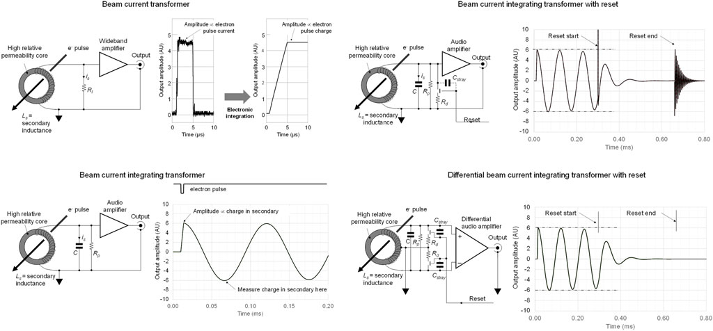
FIGURE 1. Top left: conventional beam current transformer with secondary current is flows through load resistor Rl; the electron pulse waveform is reproduced and may be integrated in subsequent electronic processing. Bottom left: conventional beam current integrating transformer where is initiates a resonance. Top right: beam current integrating transformer with damping, where artefacts from reset switch charge feedthrough through Cstray result in spurious signal that may interfere with subsequent processing of signals. Bottom right: differential beam current integrating transformer, where all reset artefacts are suppressed, leaving the system ready for the ‘next’ electron pulse.
A switched damping resistor,
In practice, even though the inductor responds to magnetic fields only, some electric field coupling takes place since the cores tend to be physically large in order to allow beam traversal. A differential arrangement is much less prone to such interferences. An electrostatic shield can be placed around the inductor to further eliminate any such unwanted signals.
It is noted that the switched damping resistor could also be replaced by using a soft, slow release that allows the shunting impedance to rise slowly. This approach has been exploited [48] using a field-effect transistor operated as a voltage-controlled resistance, driven by an exponentially decaying shorting waveform. Such an approach would still require time to complete the reset process. When used with high repetition rate machines, the differential approach presented here offers a fast-acting and easy-to-implement solution.
2.2 BCT and BCIT output comparison
It is constructive to compare the performance of BCTs, BCITs and differential BCITs and examine practical requirements. While the BCT signal is clearly simpler to ‘understand’, describing the pulse amplitude, shape and width, the BCIT signal carries information only about pulse-integrated charge. Attempts to derive other pulse characteristics as provided by the BCT from a BCIT signal, through differentiation of the leading edge, would result in comparable or worse signal-to noise ratios than what BCTs provide.
Both high and low frequency specification of BCTs needs to be considered. For typical 1–4 μs wide linac macro-pulses, a decay time constant of at least ×102 to ×103 higher is required if the pulse is to be faithfully reproduced. While BCTs with responses down to DC have been developed [52, 53], the decay time constant in simple single-winding BCTs is determined by the secondary inductance Ls and the load resistance,
Typical inductances of 100 mH are necessary when
In the case of BCITs, the resonance frequency,
Similar limitations to those associated with BCT inductance apply to BCITs in order to ensure that charge pulses are integrated with minimal error. It can be shown [48, 49] that the percentage error
For a <1% integration error, a resonant frequency of <∼22.2 kHz should be attained. Using the same inductance as in the BCT (100 mH), this suggests a ∼500 pF integrating capacitor.
In the above example (100 turns) a typical FLASH electron pulse current of 50 mA peak (200 nC in 4 µs) will thus result in a secondary current of 0.5 mA peak. A peak output voltage of 25 mV across a 50 Ω load will be obtained using a BCT.
The output voltage of a BCIT, for the same charge and number of turns can be calculated using equation (2) and found to be 4 V, a factor of 160x higher, clearly demonstrating the superior output afforded by the use of a BCIT. Furthermore, a BCT output would need to be boosted by a high bandwidth amplifier, of bandwidth >5 MHz for typical slow rise/fall times present in a linac output pulse. In the case of a BCIT, subsequent processing bandwidths need not exceed a few tens of kHz.
The minimum charge detectable by a BCT depends on the noise voltage generated by a load resistor and by current noise performance of any subsequent amplifier. When the load is, e.g., 50 Ω, the resulting thermal noise is ≈ 2 μV over a 5 MHz bandwidth and at room temperature, as derived from the usual thermal noise relation:
Where
In order to perform a comparison, it will be assumed that the gain of the subsequent amplifier is 160x, and that a well-designed voltage amplifier would have a noise voltage density of ∼1–2 nV Hz-1/2, resulting in a total input-referred noise voltage of ∼500 μV. The rms signal-to-noise ratio (SNR), for a 200 nC charge, in this example is 50:1. Of course once the BCT output is integrated in a subsequent signal processing system, the Signal to Noise Ratio (SNR) improves as the measurement bandwidth is reduced.
In the case of the BCIT the noise performance is determined by (a) the thermal noise of the real part of the effective source impedance, (b) the noise generated by the amplifier input current flowing across
where
The value of
The rms SNR in a BCIT, for a 200 nC charge, is thus >> 104:1 and this is achieved without any signal processing. In the case of the differential BCIT, it would not be expected that this SNR would reduce significantly, since the amplifier noise contribution would remain small.
If we were to integrate the BCT output for, say ∼100 µs, (a typical time similar to when a BCIT reading would be obtained) its SNR would improve to ∼2000:1; this is still worse that what can be achieved with a BCIT.
However, the noise performance of the BCT can be improved substantially by increasing the core permeability and achieving the required inductance using fewer turns and hence providing a higher is. Furthermore, as the pulse width is reduced, the BCT’s SNR for a constant charge pulse improves. A significantly better approach is to increase the BCT Ls/
Whichever approach is used, a BCT always operates as an alternating current transformer and cannot transmit a direct current component: the transformer output voltage must have positive and negative portions of equal area [47]. This implies that there is a need for some form of baseline restoration to be applied. In addition, the winding resistance places a limit on the highest Ls/
The use of BCIT is generally advantageous as large signals can be readily obtained for typical linac macro-pulses used during both FLASH and CONV irradiations, using cores of even moderate relative permeability. More importantly, when CONV irradiations are performed, the SNR of BCTs can all too easily become limiting. One of the specific advantages of the BCIT is that the same charge monitoring system can be used for CONV and FLASH irradiations and that measurements are acquired long after most accelerator-induced interference has elapsed.
The BCIT described here was used with an in-house developed, FLASH-optimised [13] 6 MeV nominal electron energy horizontal-firing electron linac. This is constructed around a travelling wave accelerating waveguide (type SL75TW, Elekta, Crawley, United Kingdom), an S-band (2.89 GHz) magnetron radiofrequency source (type MG5125, Teledyne e2v—United Kingdom, Chelmsford, United Kingdom) conventionally modulated by a thyratron (type CX1140, Teledyne e2v—United Kingdom, Chelmsford, United Kingdom) and a 4 μs pulse forming network. Radiofrequency, and hence electron, pulse triggering is performed by a phase-locked-loop with a 25 Hz reference (derived from 50 Hz ac mains) capable of providing pulse repetition rates in the range 25–300 Hz. Electrons are generated by a diode type of gun that is pulsed synchronously with the radiofrequency source and that can deliver any required number of pulses. The electron beam current is varied by changing the thermionic emission temperature of the gun. The BCIT is placed after the accelerating waveguide and before a thin output window (10 μm thick beryllium-copper foil); electron pulses are fired into a temperature controlled experimental area. Additional beam scattering is usually employed, provided by a titanium foil, 30 μm thick, positioned 8.5 mm downstream from the output window.
Since a travelling wave type of electron linac is used, the beam output energy can be readily varied by slight detuning of the magnetron matching network. The beam energy is monitored [62] and is maintained at a constant value irrespective of electron pulse amplitude.
2.3 A practical differential BCIT
A differential BCIT was developed around a ferrite core of 26 ± 0.8 mm thickness, 107 ± 2 mm outer diameter and 65 ± 1.3 mm internal diameter (3F3 material from Ferroxcube, Netherlands, T107 format, available at the time of writing from Farnell Ltd, Canal Rd, Armley, Leeds United Kingdom as part #2103396). The relative permeability of the 3F3 ferrite is ∼2000 at 25°C, though this value rises with temperature to ∼2,500 at 50°C. We note that this particular ferrite is far from optimal but was readily available at low cost. If required, significantly better performance can be achieved by using other core types, as listed in Supplementary Information S2.
The core was first protected with transformer tape and was wound with 2 × 70 turns using 0.55 mm diameter enamelled copper wire, spaced ∼1 mm between turns on the core inner diameter. The wound core was dipped in polyurethane varnish, dried, overwound with insulating transformer tape and again dipped in varnish. The core inductance factor is specified as 5.184 µH, suggesting that an inductance of 101.6 mH would be obtained.
The completed core is then fitted onto the accelerator output beam line, as shown in Figure 2. An earthed electrostatic screen surrounds the core, coil connections are brought out of the inner end-cheeks through low loss PTFE feedthroughs and these connect directly to a differential amplifier placed within the outer shield. This inner shield makes it easy to perform electrical calibrations without risk of interference injection. The outer shield is only connected to the beam line and serves to provide a return path for the electron pulse back to the accelerator.
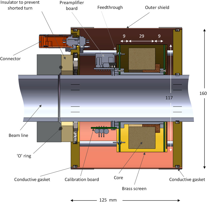
FIGURE 2. Construction of BCIT around a 50.8 mm diameter beam line. The wound core is enclosed in an electrostatic shield fashioned from copper-clad FR4 printed circuit board end cheeks a brass screen cover; a break in the board copper ensures that a shorted turn is not formed. The electron beam return path is ensured by using an outer shield made from brass end-plates and a copper outer cover, using conductive gaskets to ensure good electrical continuity. An insulating portion on the beam line prevents the formation of a shorted turn in this outer metalwork. A differential preamplifier board and a calibration board are fitted on either side of the beam line is fitted next to the wound core as is a calibration board.
Other construction methods can also be used without significant changes in performance; the approach described here was appropriate for our installation. It is, of course, essential that no shorted turns are accidentally formed; it is also important that the whole system is made mechanically rigid so as to prevent induction of signals from external magnetic fields. Furthermore, since stray capacitance is always present, a rigid mechanical construction ensures stable sensitivity.
The differential BCIT was simulated using LTspice XVII® [63] and the circuit was excited with pulses of different charge. The simulation was performed using measured inductance, capacitance and core parameter values; the resonance damping resistors, Rd, were 2 × 15 kΩ and 3 pF switch feedthrough capacitance was assumed. Following resonance excitation and a few cycles of oscillation, a reset pulse (∼360 μs wide) was simulated. The differential outputs, shown in the top panels of Figure 3, show the expected response and clean damping of the resonance. The lower panels of Figure 3 show the single-ended responses at either end of the transformer. It is clear that as the input charge is reduced, artefacts resulting from reset switch feedthrough become more prominent at the differential approach eliminates these unwanted signals.
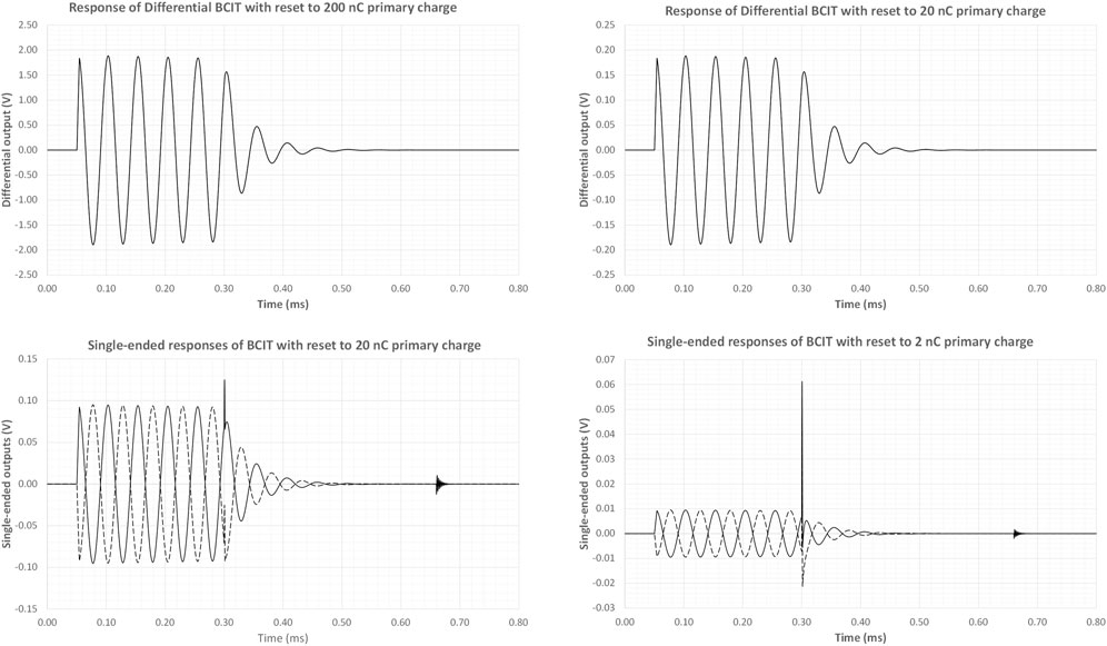
FIGURE 3. LT Spice Simulations of BCIT responses for different charge inputs. Additional charge is introduced by the leading edge of the reset pulse while the trailing edge excites a series resonance from the feedthrough capacitance and the transformer inductance. These additional charges become increasingly prominent as the primary charge is reduced, but are eliminated through differential sensing.
2.4 BCIT signal processing
The differential damping pre-amplifier is presented in Figure 4. This is based around an INA111 instrumentation amplifier, U1 in Figure 4, (Texas Instruments Inc, Dallas, Texas) that features low input bias currents and that provides negligible loading of the tuned circuit. The resonance damping was achieved by using U2 and U3 in Figure 4, a pair of field-effect opto-couplers, (type H11F1, Onsemi, Phoenix, Arizona, United States). The gain of the instrumentation amplifier is made switchable, using x1, ×10 and ×100 relative amplification factors, permitting a very wide dynamic range to be covered. Gain switching is performed with a pair of reed-relays (type 9007-12-01, Coto Technology, Tokyo, Japan) energised with a bipolar control signal through diodes D1-D4. The gain-setting resistor values shown provide the correct gain within ±0.02% and were made up using selected resistors, measured with a component bridge (model LCR400, Thurlby-Thandar Instruments Ltd. Huntingdon, Cambs., United Kingdom). The full-scale output, at a ×1 gain, corresponds to 1 μC. Should a less sensitive system be required, the value of tuned circuit capacitance (C in Figure 4) can be increased and the resonant frequency lowered. For convenience, we used a value for C such that a sensitivity of 100 nC/V was obtained: for 140 turns, 714.3 pF is required, made up from the parallel combination of a physical tuning capacitor and system stray capacitance; see Supplementary Information S3 for details.
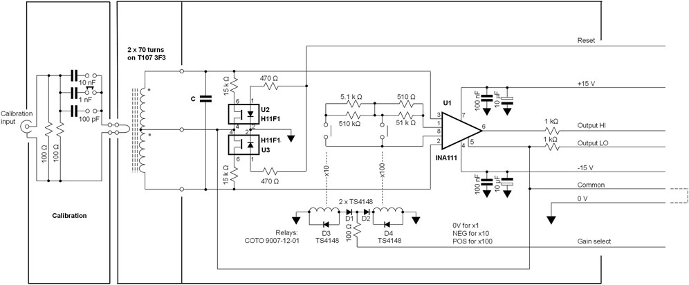
FIGURE 4. Circuit diagram of the BCIT differential preamplifier. The circuit is constructed on a double-sided printed circuit board, 85 × 25 mm.
No physical
We did not perform a detailed analysis on core losses, since the complex permeability of many commercially available soft ferrites (such as the 3F3 material used in this work) varies with frequency; nevertheless, straightforward modelling approaches are available [64] for readers who may be interested in using alternative ferrites. In this application, core losses are quite acceptable and cause a repeatable decay of <<0.5% of the integrated charge signal in the first quarter cycle of the resonance.
Photographs of the internal components of the charge monitor are presented in Figure 5. A “break” in the printed circuit board end-cheek prevents the formation of a shorted turn. No special precautions were used during construction other than ensuring that the differential amplifier input circuitry is arranged in a symmetrical manner.
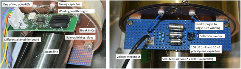
FIGURE 5. Practical details of BCIT front-end electronics. Left: the BCIT differential preamplifier board. Right: the BCIT calibration board.
Absolute charge calibration is achieved by using a single turn winding and a series capacitor across a voltage step generator. A precision polystyrene capacitor, in the range 0.1–10 nF and a known voltage step thus generate a known charge input. In our set-up we are able to choose between three capacitor values, as shown on the left of Figure 4 and on the right of Figure 5.
Although output data can be captured and analysed directly on a modern digital oscilloscopes with a deep memory, it is convenient to use a peak detector to sample the first negative peak of the differential amplifier output. This circuitry is shown in Figure 6 and is installed remotely from the charge sensor. A simple difference amplifier, U4, (type INA133, Texas Instruments Inc, Dallas, Texas, United States) takes care of any common mode voltages that may be introduced between the two locations. A conventional peak detector, formed by U5-7 and D5-6, provides the required output signal that can be subsequently sampled. The high slew rate of U5 (type ADA4637-1) copes with reverse recovery while U7 (type AD825) prevents droop on the peak-hold capacitor, 10 nF polystyrene, while the analogue switch, U6, type ADG1201 features a <1 pC charge injection. These devices are manufactured by Analog Devices Inc (Wilmington, MA, United States).
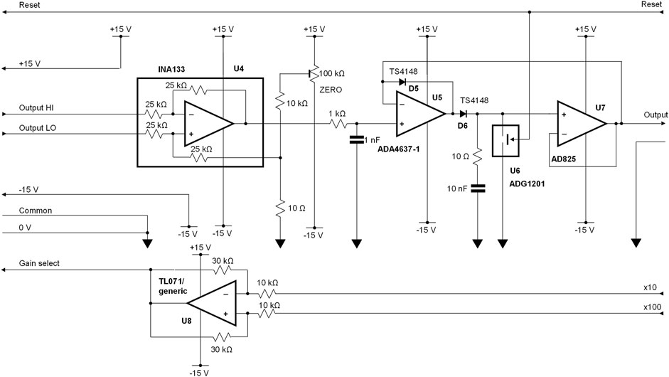
FIGURE 6. Peak detector interface between the differential amplifier and subsequent signal digitisation. For clarity, power supply decoupling components are not included in this circuit diagram.
Any small DC offsets can be corrected using a trimmer potentiometer. There is a 4% loss resulting from the use of two 1 kΩ line isolating resistors at the output of the differential amplifier. This is readily compensated for in software. Finally, a generic operational amplifier is used to drive the gain control line from logic gain-control inputs.
A transient digitiser, (PicoScope 6403, 200 MHz Bandwidth, 1 GS/s, 512 MS memory; Pico Technology, St Neots, Cambs., United Kingdom) is used to acquire charge data from the beam pulses. Alternatively, a custom-designed digitiser (Supplementary Information S4) can be used to provide statistical data of beam performance, pulse counting, etc. and to stop accelerator pulsing when the required charge or dose is delivered.
2.5 Timing
There is nothing particularly critical about timing signals required by the BCIT. While the device could be operated in a mode where a reset pulse is generated a few milliseconds after an output above, e.g., 10 mV were detected, in practice it is much simpler to use a pre-trigger pulse derived from the accelerator timing system. This pre-trigger pulse is delayed and acts as a reset pulse, e.g., <2 ms after the linac pulse. Any jitter in this pulse is not critical, provided enough time is allowed for the reset action (>0.5 ms) and for any data acquisition systems to acquire and transfer charge data. Since most linacs operate at repetition rates of <500 Hz, this requirement is easily satisfied.
2.6 Beam measurements
Dose deposition measurements were performed using solid water (15 × 15 cm2 rectangular slabs to a total of 10 cm of RW3, PTW Freiburg GmbH, Freiburg, Germany) and with radiochromic film (EBT-XD, Ashland Inc., Covington, KY, United States). The films were read out with a film scanner (Epson Perfection v850 Pro, Seiko Epson Corporation, Nagano, Japan) and analysed with ImageJ (version 1.52a, Wayne Rasband, NIH, United States). The films were previously calibrated in a 6 MeV clinical electron beam from a Varian Truebeam (Varian Medical Systems Inc., Palo Alto, CA, United States) linac at the Churchill Hospital site in Oxford, United Kingdom.
An Advanced Markus® ionisation chamber (AMC) (model 34045, PTW-Freiburg, Freiburg, Germany) was used for dose measurement in conjunction with an electrometer (UNIDOS webline, PTW-Freiburg, Freiburg, Germany). The chamber was operated at a bias voltage of −300 V.
3 Results
3.1 Charge response
The response of the calibrated differential BCIT to electrical charge pulses introduced through the single-turn calibration winding are presented in Figure 7. These data indicate a good dynamic range and acceptable readout errors in the range of 20 pC to 1 μC.
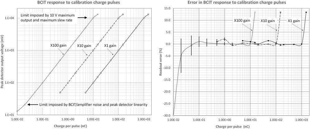
FIGURE 7. Left: Differential BCIT monitor response to electrical charge pulses introduced through the calibration single-turn winding for different gains, covering the range 20 pC/pulse to 1 μC/pulse: the charge is defined by the amplitude of a voltage step from a pulse generator and by the single-turn coupling capacitor. Right: Percentage readout errors across the same gains and the same input charge/pulse range. For clarity, error bars (±1 SEM) are only included for charges below 2 nC. Readings for 25 pulses were used to calculate SEM limits.
The plots also indicate an acceptable overlap across ranges. On the most sensitive range, differential amplifier and peak detector DC offsets were removed. It was not readily possible to estimate the absolute error as we did not have access to a step generator of adequate precision, but there is no reason to expect that this could not be calibrated out. In use, it is always preferred to use the highest gain possible, commensurate with the ∼10 V maximum output.
BCIT responses to our linac output pulses (nominally 3.8 μs wide) are summarised in Figure 8. In the top panel, the differential amplifier gain is set to unity. At the 50 μs/division timebase, not enough time has elapsed to show the start of the reset signal. The charge integration at the start of electron pulse is obvious. However, it is clear that some charge is lost, resulting from core losses, at each half-cycle subsequent to the start of the resonance. This is commensurate with the expected decay resulting from resonance curve bandwidth (Supplementary Information S3).
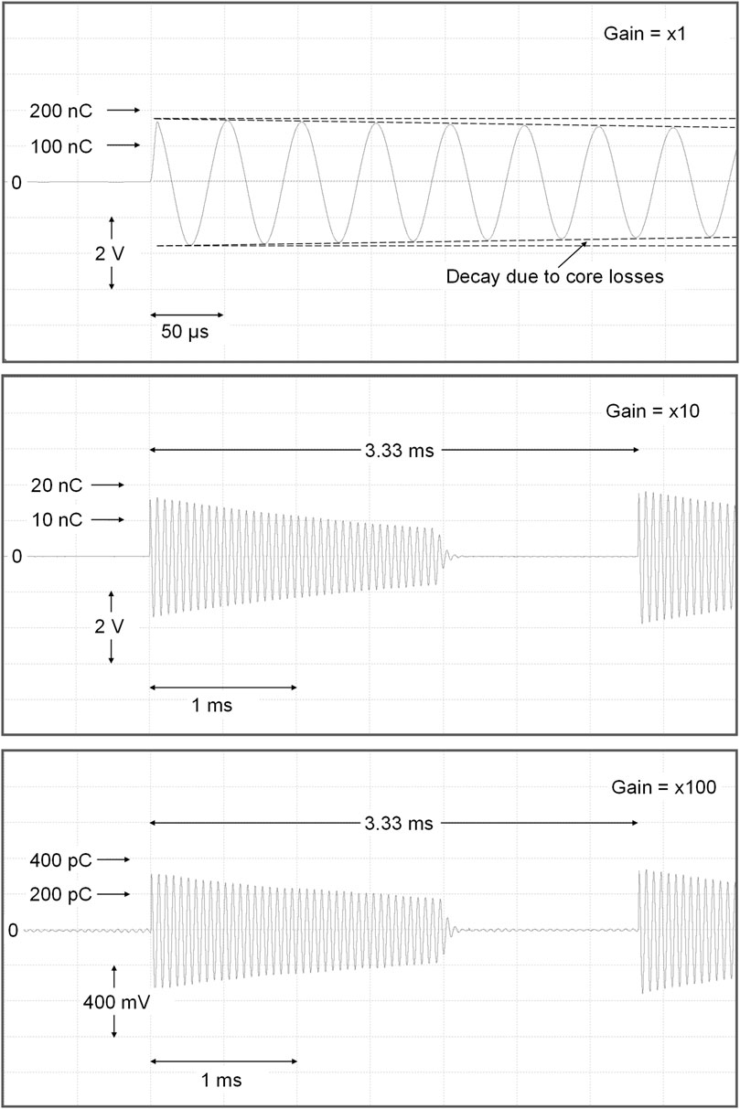
FIGURE 8. Responses of the differential BCIT to individual 3.8 μs linac electron pulses, ranging from 330 pC to 170 nC, using sensitivities of 100 nC/V (top). 10 nC/V (middle) and 1 nC/V (bottom).
In Figure 8 middle panel, the differential amplifier gain is set to x10 and the timebase of the recording instrument/display is increased to 0.5 ms/div. The linac pulse repetition frequency is 300 Hz. A clean damping of the resonance is observed starting some 2 ms after the electron pulse. Finally, in the lower panel of Figure 8, the amplifier gain is increased to x100. In this last trace, output band-limited baseline noise is observed ∼5.6 mV rms or ∼8 mV peak-peak, (equivalent to ∼8 pC peak-peak). This narrowband noise waveform is just what would be expected in a resonant system such as that used here. Inevitable mechanical vibrations of our beam line contribute to this noise, as do varying magnetic fields not related to the beam pulse. Charges per pulse of <∼20 pC on a pulse-pulse basis should be avoided, corresponding to 20 mV output (×100 gain) and ∼5 μA peak pulse current. However, since FLASH is usually performed over <200 ms, charge from ten or more pulses is summed and the noise induced errors can be considered negligible, even when lower peak currents are employed during longer-lasting CONV irradiations. The charge monitor can be used to good effect to optimise the accelerator tuning during FLASH irradiations, as shown in the Supplementary Information, Supplementary Figure S4.
3.2 Application of the differential BCIT as dose monitor
As mentioned earlier, charge and dose are distinctly different physical quantities. Nevertheless, dose can be monitored with a charge monitor when beam energy, beam position and beam scattering are kept constant. In our case, since the core was wound evenly and since the beam diameter within the monitor is small we would not expect to, and we do not, observe significant changes in response to a given charge resulting from beam movement. On the other hand, any angular beam movement is likely to affect the dose distribution at the sample.
In Figure 9, measurements of dose with radiochromic film (mean across a 5 × 5 mm2 areas in the centre of films, 23 × 34 mm) are compared with measurements of charge from the AMC and with beam charge as determined by the BCIT. Both film and the AMC were positioned in the centre of the horizontal beam, at 10 mm depth in solid water, and at a source-to-surface distance (SSD) of 50.0 cm, (see Supplementary Information S7) and measurements of charge from the BCIT, during CONV irradiations at 25 Hz pulse repetition rate and low pulse currents (left panel) and during FLASH irradiations at 300 Hz repetition rate and high pulse currents (right panel). The charge per pulse was varied by adjusting the beam injection at the accelerator’s gun and all data at a given charge per pulse were acquired simultaneously. Our installation includes an energy monitor [62] and the data presented in Figure 9 have been acquired under conditions where the energy has been maintained constant (at 6 MeV).
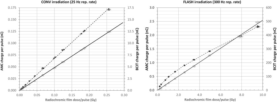
FIGURE 9. Left panel: Response of AMC (dotted line and filled circles) and BCIT (solid line and open triangles) dose monitors during CONV irradiation performed with low peak current, (∼25 μA - 1 mA) low repetition rate (25 Hz) electron pulses. Right panel: Response of AMC (dotted line and filled circles) and BCIT (solid line and open triangles) dose monitors during FLASH irradiation performed with high peak current, (∼1–>100 mA) high repetition rate (300 Hz) electron pulses. In both panels, the error bars correspond to a 2% uncertainty in dose measurement with radiochromic films.
While the BCIT can readily monitor dose per pulse ranging from <<2 cGy/pulse to over >>5 Gy/pulse, many older linacs, such as ours, are subject to beam loading effects [65, 66] that inevitably result in changes of beam energy at very high charges per pulse. More modern linac designs are less prone to such effects, and BCITs can then operate as excellent dose monitors well above several tens of Gy/pulse.
At low charges per pulse, the readout from the AMC is linear and dose monitoring can be performed successfully, as would be expected, as shown on the left panel of Figure 9.
However, at high charges per pulse, and doses per pulse above 0.2–0.5 Gy, the AMC output is no longer proportional to dose per pulse or charge per pulse: the AMC’s ion collection efficiency decreases as the dose per pulse increases [18, 67, 68], in accordance with Boag theory, extended to include a free electron component [69, 70] as well as other experimentally derived corrections [24, 71]. Linearity is, however, preserved in the BCIT’s response, as shown in the right panel of Figure 9, up to at least ∼10 Gy per pulse. The relationship between beam charge and dose is, of course dependent on the irradiation geometry.
In its current state, our accelerator provides only nominal 3.8 μs wide pulses as the short-pulsing driver has been de-commissioned. Many other installations reduce the pulse width for CONV irradiations. We reduce the pulsing repetition rate, down to 25 Hz, from 300 Hz used during FLASH irradiations. The expected variation when shorter pulses are used are presented in Supplementary Information S8. It is clear that the charge monitor, when used for monitoring dose, can provide similar information to “Monitor units (MUs)” conventionally employed [72] for dose delivery monitoring. The long-term (6 months) absolute stability of the calibration of the device has been found to be ±5% (SD) for doses of the order of a few Gy/pulse and ±2.6% (SD) for doses of the order of a few mGy/pulse. These errors include errors resulting from potential beam misalignment. The device can thus provide an indication of dose delivered to a particular sample geometry in real time. Long-term electrical calibrations (i.e., determined by introducing known voltage steps through the calibration winding and capacitor) have been found to be <±0.5% (SD).
4 Discussion
A non-intercepting beam charge monitor that can be used for dose monitoring has been presented. It is noted that even though this device is far from optimal, its simplicity and performance make it particularly suitable for use during both FLASH and CONV irradiations. The device is based on a resonant toroidal transformer, arranged in a balanced configuration in order to permit fast damping of the resonance in between electron pulses, a requirement for use with high pulse repetition rates. In principle, with appropriate changes in reset timing, pulse repetition rates in excess of several thousand pulses per second could be handled.
The magnetic performance of the core can be improved substantially by using more stable, higher permeability materials, as described in Supplementary Information S2. The particular core used is, however, readily available at low cost. This charge monitor was installed in 2015 and has operated without problems since that time. We have not observed any radiation-induced damage to the electronics. One potential disadvantage of the approach presented here is that the differential amplifier has to be mounted physically close to the toroidal winding and is thus not readily radiation shielded. Nevertheless, no obvious radiation damage has been observed after several years’ operation. The simplicity, immunity from accelerator induced noise and low cost of signal processing are all considered be advantageous.
We have presented results here using nominal 3.8 μs electron pulse width. However, the same device has been used without problems with much shorter electron pulses, down to ∼15 ns and below, using a now de-commissioned short pulse driver. Our intention was to highlight operation for commonly used 4 μs linac macro-pulses, where the BCITs offer significant advantages over BCTs that have attracted recent attention when used for FLASH. Although we used a peak detector to provide a charge-pulse readout, software peak detection could also be exploited.
The device described here is appropriate for pulsed electron beams. In principle a lower sensitivity version of the same could be used for emerging photon FLASH sources [73, 74], although the sensitivity of BCTs is likely to be adequate for such work, when intense electron pulses are used on a photon-generating target. Many specialised electron linacs that are used for electron irradiation also generate pulses in the 1–4 μs region and charges in the range 4 nC to ∼2.50 μC [75, 76]. Similar beams are generated by FLASH and intraoperative radiotherapy (IORT) machines. For FLASH, typical maximum charges/pulse of 400 nC are used, delivered at 100 mA peak and 4 μs pulse width (corresponding to ∼2.5 × 10¹² electrons). Our monitor readily monitors charge per pulse in this range, with an upper limit of ∼1 μC/pulse for a 10 V output signal. For other pulsed charge monitoring applications, charges/pulse ∼20 pC can be measured with repetitive sources when much of the BCIT/amplifier noise is subtracted out, corresponding to peak currents of ∼5 μA. Though unnecessary for work with linacs, this lower limit can be readily extended by using higher permeability, lower loss cores, as outlined in the Supplementary Information S2, down to a few picocoulombs.
Our results clearly show the benefit of using BCIT to monitor dose delivery during FLASH studies, as the BCIT response is linear with dose (as measured with film) over the dose rate range tested (0.1 Gys−1–3 kGys−1). Measurements with an ionisation chamber (AMC) in the same dose rate range shows a loss of linearity above 0.2–0.5 Gy per pulse, due to decrease in ion collection efficiency with increasing dose per pulse (Figure 9).
Neither BCTs or BCITs are able to provide beam cross-section and spatial distribution information since they are only sensitive to the beam charge passing through them. Other approaches must be used for determination of beam dimensions, flatness, symmetry energy and other parameters [77, 78].
The BCIT described here is mainly aimed at work with electron macro-pulses generated by electron linacs; dose monitoring must be provided in such machines used clinically, where the IEC 60601-2-1 Medical electrical equipment standard applies [34], in conjunction with IEC 60976 [76]. While a BCT can be used to monitor temporal variations of instantaneous beam current, it requires a large signal processing bandwidth and its output must be digitised, baseline-restored, and integrated in software in order to derive a value for beam pulse charge. Integration is inherent in a BCIT and it does not require a large measurement bandwidth. The sensitivity possible with a BCIT is therefore excellent. While there are few fundamental reasons why a BCT system of comparable sensitivity cannot be developed, practical realisations with BCTs tend to be complex. BCTs demand the use of a few turns in order to provide good sensitivity, and the core must therefore have a very high permeability in order to provide enough inductance to support the pulse width. BCTs can also be constructed in a balanced arrangement in order to provide adequate rejection of accelerator-induced electrical noise [79]. Charge calibration is also much simplified in BCITs compared to BCTs.
BCTs provide information on temporal pulse profiles. In most machines, instantaneous dose rate changes within the pulse are minimised. Nevertheless, the output pulses are rarely associated with a flat ‘top’ and are often associated with overshoots and undershoots/oscillations during the pulse. Although the FLASH phenomenon is dose-rate dependent, it is unlikely that such dose rate variations within the pulse are responsible for the biological findings and in all published work to date with BCTs, the current pulse is integrated in software.
Other similar machines developed for FLASH work [80–82] and linear induction accelerators [73] provide beams appropriate for monitoring with the device described here. The optimum resonant frequency, for lowest narrowband noise, is ∼50–60 kHz and macro-pulses would then be limited to ∼1–2 μs. The use of lower number of turns, e.g., 2 × 5–10 turns on very high permeability cores will always be beneficial, provided the resonant frequency is appropriate for the pulse width utilised.
For protons or hadron FLASH irradiations, where charges per pulse are lower and pulse structures are varied [83, 84], the challenges are distinctly different [85]. More complex inductive monitoring such as parametric beam monitors [52, 86] that can operate down to DC or synchronous beam monitors [87] would perhaps be better suited, while other types of monitoring can also be used [88].
5 Conclusion
Key information for the design of a beam charge integrating transformer that exploits resonance to achieve a high sensitivity has been presented. Simple additions to permit use of such resonant transformer with high repetition rate pulsed electron beams have been described. Such non-intercepting beam charge monitors can be used to monitor dose delivery during both CONV and FLASH irradiations, or indeed when single, individual, pulses are used. A wide dynamic range can be readily handled. They are not susceptible to saturation effects and can thus be used for high charge/pulse FLASH beams. However, the charge in CONV beams can be also monitored with the same device, as a result of their good sensitivity.
Although resistively-loaded beam current transformers have gained recent popularity for use during electron FLASH measurement, their sensitivity, particularly for long pulses, is often not optimal. Furthermore, such transformers require wide bandwidths, hardware- or software-based integration along with baseline correction. One of our aims in presenting this work was to bring to the foreground resonant inductive beam sensors that inherently integrate the beam charge per pulse and offer far greater versatility during radiobiology experiments using electron pulses. Physicists are interested in temporal pulse profiles, and rightly so. Dose per pulse, however, is of greater immediate interest to radiobiologists. The low electrical bandwidths of BCITs and almost perfect immunity from accelerator-generated noise provides a significant advantage in work involving charge pulses acquired over a wide dynamic range, including when low doses/pulse need to be monitored. The charge measurement is performed several hundred microseconds after the electron pulse and is thus free of any interference generated by the linac modulator and radiofrequency system. It is hoped that these versatile devices will gain wider acceptance by the electron FLASH community.
Data availability statement
The original contributions presented in the study are included in the article/Supplementary Material, further inquiries can be directed to the corresponding author.
Author contributions
All the authors substantial contributions to conception and use of the device, designed by BV and IT, who also performed electrical data acquisition while RN performed all electronic construction. KP and IT acquired all dosimetry data. All authors contributed to the article and approved the submitted version.
Funding
Past financial support of Cancer Research UK and current financial support Cancer Research UK—RadNet (C6078/A28736) is gratefully acknowledged. We thank the Medical Research council for providing funds towards the linac shielding and for current financial support through a programme grant (MR/X006611/1). We also thank the National Cancer Institute/NIH/DHHS for their support towards this work (1P01CA257904).
Acknowledgments
The contribution of the Department of Oncology Mechanical Workshop has been essential for the completion of this work: thanks go to John Prentice, Kyle Hallett, and Gerald Shortland for their patience in machining disparate materials that fitted together just as our mechanical models predicted they would!
Conflict of interest
The authors declare that the research was conducted in the absence of any commercial or financial relationships that could be construed as a potential conflict of interest.
Publisher’s note
All claims expressed in this article are solely those of the authors and do not necessarily represent those of their affiliated organizations, or those of the publisher, the editors and the reviewers. Any product that may be evaluated in this article, or claim that may be made by its manufacturer, is not guaranteed or endorsed by the publisher.
Supplementary material
The Supplementary Material for this article can be found online at: https://www.frontiersin.org/articles/10.3389/fphy.2023.1185237/full#supplementary-material
References
1. Favaudon V, Caplier L, Monceau V, Pouzoulet F, Sayarath M, Fouillade C, et al. Ultrahigh dose-rate FLASH irradiation increases the differential response between normal and tumor tissue in mice. Sci Transl Med (2014) 6(245):245ra93. doi:10.1126/scitranslmed.3008973
2. Loo BW, Schuler E, Lartey FM, Rafat M, King JG, Trovati S, et al. P003) Delivery of ultra-rapid flash radiation therapy and demonstration of normal tissue sparing after abdominal irradiation of mice. Int J Radiat Oncol Biol Phys (2017) 98:E16. doi:10.1016/j.ijrobp.2017.02.101
3. Montay-Gruel P, Petersson K, Jaccard M, Boivin G, Germond J-F, Petit B, et al. Irradiation in a flash: Unique sparing of memory in mice after whole brain irradiation with dose rates above 100 Gy/s. Radiother Oncol (2017) 124:365–9. doi:10.1016/j.radonc.2017.05.003
4. Bourhis J, Montay-Gruel P, Gonçalves Jorge P, Bailat C, Petit B, Ollivier J, et al. Clinical translation of FLASH radiotherapy: Why and how? Radiother Oncol (2019) 139:11–7. doi:10.1016/j.radonc.2019.04.008
5. Bourhis J, Jeanneret Sozzi W, Gonçalves Jorge P, Gaide O, Bailat C, Duclos F, et al. Treatment of a first patient with FLASH-radiotherapy. Radiother Oncol (2019) 139:18–22. doi:10.1016/j.radonc.2019.06.019
6. Montay-Gruel P, Meziani L, Yakkala C, Vozenin M. Expanding the therapeutic index of radiation therapy by normal tissue protection. Br J Radiol (2019) 92:20180008. doi:10.1259/bjr.20180008
7. Vozenin M-C, De Fornel P, Petersson K, Favaudon V, Jaccard M, Germond J-F, et al. The advantage of FLASH radiotherapy confirmed in mini-pig and cat-cancer patients. Clin Cancer Res (2019) 25:35–42. doi:10.1158/1078-0432.CCR-17-3375
8. Wardman P. Radiotherapy using high-intensity pulsed radiation beams (FLASH): a radiation-chemical perspective. Radiat Res (2020) 194:607–17. doi:10.1667/RADE-19-00016
9. Adrian G, Konradsson E, Lempart M, Bäck S, Ceberg C, Petersson K. The FLASH effect depends on oxygen concentration. Br J Radiol (2020) 93:20190702. doi:10.1259/bjr.20190702
10. Wilson JD, Hammond EM, Higgins GS, Petersson K. Ultra-high dose rate (FLASH) radiotherapy: silver bullet or fool’s gold? Front Oncol (2020) 9:1563. doi:10.3389/fonc.2019.01563
11. Maxim PG, Keall P, Cai J. FLASH radiotherapy: Newsflash or flash in the pan? Med Phys (2019) 46(10):4287–90. [published online ahead of print 2019/06/28]. doi:10.1002/mp.13685
12. Friedl AA, Prise KM, Butterworth KT, Montay-Gruel P, Favaudon V. Radiobiology of the FLASH effect. Med Phys (2022) 49:1993–2013. doi:10.1002/mp.15184
13. Ruan J-L, Lee C, Wouters S, Tullis IDC, Verslegers M, Mysara M, et al. Irradiation at ultra-high (FLASH) dose rates reduces acute normal tissue toxicity in the mouse gastrointestinal system. Int J Radiat Oncol Biol Phys (2021) 111(5):1250–61. doi:10.1016/j.ijrobp.2021.08.004
14. Okoro CM, Schüler M, Taniguchi CM. The therapeutic potential of FLASH-RT for pancreatic cancer. Cancers (Basel) (2022) 14(5):1167. [published online ahead of print 2022/03/11]. doi:10.3390/cancers14051167
15. Wu Y, No HJ, Breitkreutz DY, Mascia AE, Moeckli R, Bourhis J, et al. Technological basis for clinical trials in FLASH radiation therapy: A review. Appl Rad Oncol (2021) 2:6–14. doi:10.37549/aro1280
16. Schuler E, Acharya M, Montay-Gruel P, Loo BW, Vozenin M-C, Maxim PG. Ultra high dose rate electron beams and the FLASH effect: From preclinical evidence to a new radiotherapy paradigm. Med Phys (2022) 49:2082–95. doi:10.1002/mp.15442
17. Ashraf MR, Rahman M, Zhang R, Williams BB, Gladstone DJ, Pogue BW, et al. Dosimetry for FLASH radiotherapy: A review of tools and the role of radioluminescence and cherenkov emission. Front Phys-lausanne (2020) 8:328. doi:10.3389/fphy.2020.00328
18. Petersson K, Jaccard M, Germond J-F, Buchillier T, Bochud F, Bourhis J, et al. High dose-per-pulse electron beam dosimetry - a model to correct for the ion recombination in the advanced Markus ionization chamber. Med Phys (2017) 44:1157–67. doi:10.1002/mp.12111
19. Gonçalves Jorge P, Jaccard M, Petersson K, Gondré M, Durána MT, Desorgher L, et al. Dosimetric and preparation procedures for irradiating biological models with pulsed electron beam at ultra-high dose rate. Radiother Oncol (2019) 139:34–9. doi:10.1016/j.radonc.2019.05.004
20. Konradsson E, Ceberg C, Lempart M, Blad B, Bäck S, Knöös T, et al. Correction for ion recombination in a built-in monitor chamber of a clinical linear accelerator at ultra-high dose rates. Radiat Res (2020) 194:580–6. doi:10.1667/RADE-19-00012
21. Boag JW. Ionization measurements at very high intensities: I. Pulsed radiation beams. Br J Radiol (1950) 23:601–11. doi:10.1259/0007-1285-23-274-601
22. Boag JW, Currant J. Current collection and ionic recombination in small cylindrical ionization chambers exposed to pulsed radiation. Br J Radiol (1980) 53:471–8. doi:10.1259/0007-1285-53-629-471
23. Gotz M, Karsch L, Pawelke J. A new model for volume recombination in plane-parallel chambers in pulsed fields of high dose-per pulse. Phys Med Biol (2017) 62:8634–54. doi:10.1088/1361-6560/aa8985
24. Di Martino F, Giannelli M, Traino AC, Lazzeri M. Ion recombination correction for very high dose-per-pulse high-energy electron beams. Med Phys (2005) 32:2204–10. doi:10.1118/1.1940167
25. Fainstein C, Winkler E, Saravi M. ESR/Alanine gamma-dosimetry in the 10–30 Gy range. Appl Radiat Isot (2000) 52:1195–6. doi:10.1016/s0969-8043(00)00070-1
26. Hayes RB, Haskell EH, Wieser A, Romanyukha AA, Hardy BL, Barrus JK. Assessment of an alanine EPR dosimetry technique with enhanced precision and accuracy. Nucl Instrum Methods Phys Res A (2000) 440:453–61. doi:10.1016/S0168-9002(99)00957-2
27. Arjomandy B, Tailor R, Zhao L, Devic S. EBT2 film as a depth-dose measurement tool for radiotherapy beams over a wide range of energies and modalities. Med Phys (2012) 39:912–21. doi:10.1118/1.3678989
28. Karsch L, Beyreuther E, Burris-Mog T, Kraft S, Richter C, Zeil K, et al. Dose rate dependence for different dosimeters and detectors: TLD, OSL, EBT films, and diamond detectors. Med Phys (2012) 39:2447–55. doi:10.1118/1.3700400
29. Schüler E, Trovati S, King G, Lartey F, Rafat M, Villegas M, et al. Experimental platform for ultra-high dose rate FLASH irradiation of small animals using a clinical linear accelerator. Radiat Oncol Biol Phys (2017) 97:195–203. doi:10.1016/j.ijrobp.2016.09.018
30. Jaccard M, Durán MT, Petersson K, Germond J-F, Liger P, Vozenin M-C, et al. High dose-per-pulse electron beam dosimetry: Commissioning of the Oriatron eRT6 prototype linear accelerator for preclinical use. Med Phys (2018) 45:863–74. doi:10.1002/mp.12713
31. Lempart M, Blad B, Adrian G, Bäck S, Knöös T, Ceberg C, et al. Modifying a clinical linear accelerator for delivery of ultrahigh dose rate irradiation. Radiother Oncol (2019) 139:40–5. doi:10.1016/j.radonc.2019.01.031
32. Patriarca A, Fouillade C, Auger M, Martin F, Pouzoulet F, Nauraye C, et al. Experimental set-up for FLASH proton irradiation of small animals using a clinical system. Int J Radiat Oncol Biol Phys (2018) 102:619–26. doi:10.1016/j.ijrobp.2018.06.403
33. Diffenderfer ES, Verginadis II, Kim MM, Shoniyozov K, Velalopoulou A, Goia D, et al. Design, implementation, and in vivo validation of a novel proton FLASH radiation therapy system. Int J Radiat Oncol Biol Phys (2019) 106:440–8. doi:10.1016/j.ijrobp.2019.10.049
34. International Electrotechnical Commission. As defined by IEC 60601-2-1: Medical electrical equipment - Part 2-1: Particular requirements for the basic safety and essential performance of electron accelerators in the range 1 MeV to 50 MeV (2020).
35. Oesterle R, Gonçalves Jorge P, Grilj V, Bourhis J, Vozenin M-C, Germond J-F, et al. Implementation and validation of a beam current transformer on a medical pulsed electron beam LINAC for FLASH-RT beam monitoring. J Appl Clin Med Phys (2021) 22:165–71. doi:10.1002/acm2.13433
36. Gonçalves Jorge P, Grilj V, Bourhis J, Vozenin C-M, Germond JF, Bochud F, et al. Technical note: Validation of an ultrahigh dose rate pulsed electron beam monitoring system using a current transformer for FLASH preclinical studies. Med Phys (2022) 49:1831–8. doi:10.1002/mp.15474
37. Webber RC. Tutorial on beam current monitoring. AIP Conf Proc (2000) 546:83. doi:10.1063/1.1342580
38. Simmons RH, Ng JST. A toroidal charge monitor for high-energy picosecond electron beams. Nucl Instr Meth Phys Res A (2007) 575:334–42. doi:10.1016/j.nima.2007.03.002
39. ICRU. Radiation dosimetry: Electron beams with energy between 1 and 50 MeV). ICRU report no. 35 (1985). Med. Phys. 12, 813.
40. Klevenhagen SC. Physics of electron beam therapy medical Physics handbook. Boston: Adam Hilger Ltd (1985). p. 13.
41. Berger MJ, Seltzer SM. The Influence of scattering foils on absorbed dose distributions from electron beams NBSIR 78-1552 (1978). Available at: https://doi.org./10.6028/nbs.ir.78-1552.
42. Patil BJ, Bhoraskar V, Dhole SV. Optimization of dual scattering foil for 6-20 MeV electron beam radiotherapy. In: PAC-2011-THP010 Proc. 2011 Particle Accelerator Conf 110328; March 28-April 1, 2011; New York, NY, USA (2011). p. 2157–9.
43. Jeong DH, Lee M, Lim H, Kang SK, Lee J, Kim HC, et al. Electron beam scattering device for FLASH preclinical studies with 6-MeV LINAC. Nucl Eng Technol (2021) 53:1289–96. doi:10.1016/j.net.2020.09.019
44. Anderson JM. Wide frequency range current transformers. Rev Scientific Instr (1971) 42:915–26. doi:10.1063/1.1685307
45. Kondrath N, Kazimierczuk MK. Bandwidth of current transformers. IEEE Trans Instrum Meas (2009) 58:2008–16. doi:10.1109/TIM.2008.2006134
46. Leggieri A, Passi D, di Paolo F, Ciccotelli A, De Stefano S, Marangoni F, et al. Real-time beam monitor for charged particle medical accelerators. IEEE Trans Nucl Sci (2016) 63(2):869–77. doi:10.1109/TNS.2015.2504403
47. Pruitt JS. Electron beam current monitoring system. Nucl Instr Meth (1971) 92:285–97. doi:10.1016/0029-554X(71)90206-0
48. Steiner R, Merle K, Andresen HG. A high-precision ferrite-induction beam-current monitoring system. Nucl Instr Meth (1975) 127:11–5. doi:10.1016/0029-554X(75)90295-5
49. Zimek Z. A single-pulse toroidal coil beam-charge monitor. Radiat Phys Chem (1978) 11:179–81. doi:10.1016/0146-5724(78)90080-8
50. Vojnovic B. A sensitive single-pulse beam charge monitor for use with charged particle accelerators. Radiat Phys Chem (1984) 24:517–22. doi:10.1016/0146-5724(84)90187-0
51. Dolbilkin BS, Kondratev RL, Lisin VP, Polonsky AL. The choice of optimum parameters of a toroidal charge monitor for precision measurements. Nucl Instrum Meth.Physics Res (1984) 226:271–80. doi:10.1016/0168-9002(84)90041-X
52. Unser K. Beam current transformer with DC to 200 MHz range. IEEE Trans Nucl Sci (1969) 16:934–8. doi:10.1109/TNS.1969.4325406
53. Sharp JB. The induction type beam monitor for the PS: Hereward transformer MPS-Int-CO-62-15. CERN-MPS-Int-CO-62-15 (1962).
54. Telcon Ltd. Toroidal cores (2013). Lowfield Heath, Crawley, West Sussex, United Kingdom, RH11 0PR; Available at: http://www.telcon.co.uk/Toroidal%20Cores.html (Accessed July 23, 2022).
55. AguileraOdier SP, Ruffieux R. Magnetic materials for current transformers. In: Proceedings of the 2nd International Beam Instrumentation Conference; 16 - 19 Sep 2013; Oxford, UK (2013). ISBN 978-3-95450-127-4 pp263-266.
56. Mag-Inc. Magnetics, 110 delta drive, Pittsburgh, PA 15238-0428 (2018). Available at: https://www.mag-inc.com/Products/Tape-Wound-Cores/Supermalloy (Accessed July 23, 2022).
57. Lahaye C, Fontbonne J-M, Salvador S. Low noise optimization of an electron beam current transformer for conventional radiotherapy up to ultra high dose rate irradiations. J Instrumentation (2022) 17:P08018. doi:10.1088/1748-0221/17/08/P08018
58. Boriskin VN, Gurin VA, Dovbnya AN, Popenko VA, Reprintsev LV, Savchenko AN, et al. Magnetic induction monitor measurements of beam spatial characteristics in technological electron linear accelerators. Proc 2001 Part. Accelerator Conf (2001) 2:1336–8. doi:10.1109/PAC.2001.986672
59. Vojnovic B. Sensitive long pulse beam charge monitor for use with charged particle accelerators. Int J Radiat App Instrum C Radiat Phys.Chem (1987) 29:409–13. doi:10.1016/1359-0197(87)90015-4
60. Dewa H, Iwashita Y, Fujita H, Ikegami M, Inoue M, Kakigi S, et al. Pulsed Beam Current monitor with a toroidal core. In: Proceedings of the 1994 International Linac Conference; 21 - 26 August 1994; Tsukuba, Japan (1994).
61. Larky A. Negative-impedance converters. IRE Trans Circuit Theor (1957) 4:124–31. doi:10.1109/TCT.1957.1086360
62. Berne A, Petersson K, Tullis IDC, Newman RG, Vojnovic B. Monitoring electron energies during FLASH irradiations. Phys Med Biol (2021) 66:045015. doi:10.1088/1361-6560/abd672
63. Analog. LTspice version XVII downloaded from (2023). Available at: https://www.analog.com/en/design-center/design-tools-and-calculators/ltspice-simulator.html Win10 64 bit version (Accessed July 23, 2022).
64. WilsonRoss PRJN, Brown AD. Modeling frequency-dependent losses in ferrite cores. IEEE Trans Mag (2004) 40:1537–41. doi:10.1109/TMAG.2004.826910
65. Arai S, Katayama T, Tojyo E, Yoshida K. Beam loading effects in a standing wave accelerator structure. Part Accel (1980) 11:103–11.
66. Arai S, Kobayashi K, Toio E, Yoshida K. Detuning effect in a travelling-wave accelerator structure due to beam loading. Part Accel (1984) 15:99–114.
67. Gotz M, Karsch L, Pawelke J. A new model for volume recombination in plane-parallel chambers in pulsed fields of high dose-per-pulse. Phys Med Biol (2017) 62(22):8634–54. doi:10.1088/1361-6560/aa8985
68. Kranzer R, Poppinga D, Weidner J, Schuller A, Hackel T, Looe HK, et al. Ion collection efficiency of ionization chambers in ultra-high dose-per-pulse electron beams. Med Phys (2021) 48(2):819–30. doi:10.1002/mp.14620
69. Boag JW, Hochhauser E, Balk OA. The effect of free-electron collection on the recombination correction to ionization measurements of pulsed radiation. Phys Med Biol (1996) 41:885–97. doi:10.1088/0031-9155/41/5/005
70. Di Martino F, Del Sarto D, Barone S, Giuseppina Bisogni M, Capaccioli S, Galante F, et al. A new calculation method for the free electron fraction of an ionization chamber in the ultra-high-dose-per-pulse regimen. Phys Med (2022) 103:175–80. doi:10.1016/j.ejmp.2022.11.001
71. Laitano RF, Guerra AS, Pimpinella M, Caporali C, Petrucci A. Charge collection efficiency in ionization chambers exposed to electron beams with high dose per pulse. Phys Med Biol (2006) 51:6419–36. doi:10.1088/0031-9155/51/24/009
72. Gibbons JP, Antolak JA, Followill DS, Huq MS, Klein EE, Lam KL, et al. Monitor unit calculations for external photon and electron beams: Report of the AAPM therapy Physics committee task group No. 71. Med Phys (2014) 41:031501. doi:10.1118/1.4864244
73. Sampayan SE, Sampayan KC, Caporaso GJ, Chen Y-J, Falabella S, Hawkins SA, et al. Megavolt bremsstrahlung measurements from linear induction accelerators demonstrate possible use as a FLASH radiotherapy source to reduce acute toxicity. Sci Rep (2021) 11:17104. doi:10.1038/s41598-021-95807-9
74. Esplen N, Egoriti L, Paley B, Planche T, Hoehr C, Gottberg A, et al. Design optimization of an electron-to-photon conversion target for ultra-high dose rate x-ray (FLASH) experiments at TRIUMF. Phys Med Biol (2022) 67:105003. doi:10.1088/1361-6560/ac5ed6
75. Ticoş D, Scurtu A, Oane M, Diplaşu C, GiubegaI G, Călina I, et al. Complementary dosimetry for a 6 MeV electron beam. Results Phys (2019) 14:102377. doi:10.1016/j.rinp.2019.102377
76. Schüller A, Illemann J, Renner F, Makowski C, Kapsch R-P. Traceable charge measurement of the pulses of a 27 MeV electron beam from a linear accelerator. J Instrum (2017) 12:P03003. doi:10.1088/1748-0221/12/03/P03003
77. Podgorsak EB. Radiation oncology Physics: a handbook for teachers and students. Vienna: International Atomic Energy Agency (2005). Sponsored by IAEA 2005. STI/PUB/1196. ISBN 92–0–107304–6.
78. International Electrotechnical Commission. IEC 60976 Medical electrical equipment – Medical electron accelerators – functional performance characteristics, 2007 describes the tests to be performed (2007).
79. Williams AJ, Mcewen MR, Burns DT. A new beam current monitor for the NPL linear accelerator facility. NPL Technical Report number: CIRM(EXT)12, National Physical Laboratory Teddington, Middlesex, UK, TWII OLW, ISSN1369-6793 (1998).
80. Faillace L, Barone S, Battistoni G, Di Francesco M, Felici G, Ficcadenti L, et al. Compact S-band linear accelerator system for ultrafast, ultrahigh dose-rate radiotherapy. Phys Rev Accel Beams (2021) 24:050102. doi:10.1103/PhysRevAccelBeams.24.050102
81. Jaccard M, Duran MT, Petersson K, Germond JF, Liger P, Vozenin MC, et al. High dose-per-pulse electron beam dosimetry: Commissioning of the Oriatron eRT6 prototype linear accelerator for preclinical use. Med Phys (2018) 45(2):863–74. doi:10.1002/mp.12713
82. Moeckli R, Gonçalves Jorge P, Grilj V, Oesterle R, Cherbuin N, Bourhis J, et al. Commissioning of an ultra-high dose rate pulsed electron beam medical LINAC for FLASH RT preclinical animal experiments and future clinical human protocols. Med Phys (2021) 48(6):3134–42. doi:10.1002/mp.14885
83. Darafsheh A, Hao Y, Zwart T, Wagner M, Catanzano D, Williamson JF, et al. Feasibility of proton FLASH irradiation using a synchrocyclotron for preclinical studies. Med Phys (2020) 47:4348–55. doi:10.1002/mp.14253
84. Nesteruk KP, Psoroulas S. FLASH irradiation with proton beams: Beam characteristics and their implications for beam diagnostics. Appl Sci (2021) 11:2170. doi:10.3390/app11052170
85. Vignati A, GiordanengoFausti SF, Villarreal OAM, Mas Milian F, Mazza G, Shakarami Z, et al. Beam monitors for tomorrow: The challenges of electron and photon FLASH RT. Front Phys (2020) 8:375. doi:10.3389/fphy.2020.00375
86. Unser KB. The parametric current transformer, a beam current monitor developed for LEP. AIP Conf.Proc. (1992) 252:266. Published Online: 02 June 2008. doi:10.1063/1.42124
87. Covo MK. Nondestructive synchronous beam current monitor. Rev Sci Instr (2014) 85:125106. doi:10.1063/1.4902903
Keywords: FLASH, LINAC, radiobiology, electron beam charge, dosimetry, pre-clinical irradiation, pre-clinical radiotherapy
Citation: Vojnovic B, Tullis IDC, Newman RG and Petersson K (2023) Monitoring beam charge during FLASH irradiations. Front. Phys. 11:1185237. doi: 10.3389/fphy.2023.1185237
Received: 13 March 2023; Accepted: 21 August 2023;
Published: 11 September 2023.
Edited by:
Fabio Di Martino, Pisana University Hospital, ItalyReviewed by:
Giuseppe Felici, Sordina IORT Technologies S.p.A., ItalyAnna Vignati, University of Turin, Italy
Copyright © 2023 Vojnovic, Tullis, Newman and Petersson. This is an open-access article distributed under the terms of the Creative Commons Attribution License (CC BY). The use, distribution or reproduction in other forums is permitted, provided the original author(s) and the copyright owner(s) are credited and that the original publication in this journal is cited, in accordance with accepted academic practice. No use, distribution or reproduction is permitted which does not comply with these terms.
*Correspondence: Kristoffer Petersson, kristoffer.petersson@oncology.ox.ac.uk