A Comprehensive Comparison and Analysis of Several Intensity Modulations Based on the Underwater Photon-Counting Communication System
 Xiaotian Han1,2
  Peng Li1 Chang Chang1 Duorui Gao1 Dongquan Zhang1 Peixuan Liao1 Wei Wang1* Xiaoping Xie1,2*
- 1State Key Laboratory of Transient Optics and Photonics, Xi’an Insitute of Optics and Precision Mechanics, Chinese Academy of Science, Xi’an, China
- 2School of Future Technology, University of Chinese Academy of Science, Beijing, China
Underwater wireless optical communication is facing absorption, scattering problems, which, in principle, can be greatly resolved by underwater photon-counting communication (UPCC) technology that exhibits high-sensitivity communication characteristics in long-range underwater wireless optical communication. Recent studies on UPCC are mainly focused on a single intensity modulation such as on–off keying (OOK) and pulse position modulation (PPM) technologies, and the comprehensive analysis of communication performance combing OOK modulation and digital pulse modulations remains a lack. To this, by using a UPCC system based on a single-photon avalanche diode, we reveal the communication performances of OOK, PPM, differential pulse interval modulation (DPIM), differential pulse position modulation (DPPM), and dual-header pulse interval modulation, and find that (1) the PPM has the longest transmission distance at the same bit error ratio when M > 2, but the lowest communication rate under identical modulation bandwidth and average transmit power; and (2) the DPPM and DPIM perform the optimum communication performance at the fixed communication rate when M = 8. We thus conclude that the DPPM and DPIM have advantages of low modulation bandwidth and long time slot time compared with PPM, indicating the significance of reducing the difficulty of signal synchronization and the complexity of the underwater photon-counting system accordingly.
Introduction
Lasers, since their invention, have been widely used in the fields of sensing [1], communication [2], and measurement [3] because of their special characteristics such as high directionality, high brightness, monochromaticity, and good coherence. Especially in recent years, with the increase in comprehensive ocean observations in scientific, industrial, and military activities, building efficient, flexible, and reliable marine environmental sensing networks is becoming urgent and important [4]. In fact, any sensors need to be linked to each other in some way of communication, so there is great interest around how to communicate between marine mobile sensing devices in a high-speed and reliable way [5]. For underwater wireless communication, the existing communication methods mainly include hydroacoustic communication, microwave communication, optical communication, and so on [6]. Underwater wireless optical communication (UWOC) is a technology that uses the blue/green light in the visible spectrum as the information carrier for signal transmission in water [7] and has the advantages of high data transmission rate, low latency, high bandwidth, low power consumption, and so on, compared with the hydroacoustic communication and microwave communication [8]. However, achieving long-range, high-speed underwater wireless optical transmission still faces challenges due to the existence of severe water attenuation and the bandwidth limitations of blue–green wavelength devices [9]. This makes high-speed signal modulation and demodulation techniques and high-sensitivity reception techniques an important research topic in the field of UWOC. Currently, the main modulation methods include intensity modulation (IM) [10], nonlinear frequency conversion [11], subcarrier modulation [12], higher-order modulation, signal multiplexing [13], and so on. The nonlinear frequency conversion technique can generate high-speed blue–green light signals with the help of mature 1,064-nm high-power devices, but the coherence of the optical signal is demanded in the frequency doubling process that high-energy consumption is needed because of the low electro-optical conversion efficiency. Although subcarrier modulation, higher-order modulation, and signal multiplexing techniques can significantly increase the data transmission rate of the system, they require high water quality and system stability and are applicable only to the laboratory technology research stage; the adaptability of these modulation techniques to the underwater channel needs further verification. In practical engineering applications, the IM techniques represented by on–off keying (OOK) are still the preferred choice. However, the high requirements for transmitting optical power for long-range underwater communications make OOK modulation unsuitable for applications on energy-limited underwater platforms. Thus, it is necessary to study the channel suitability of IM techniques with high-power utilization efficiency for underwater channels.
High-energy utilization modulation technologies represented by pulse position modulation (PPM) and high-sensitivity reception technology represented by photon-counting have become hot topics to improve power efficiency and achieve long-distance transmission. Theoretically, Hiskett et al. [14]first proposed to apply the photon-counting reception technology into underwater communication. Mao et al. [15] formulated the output characteristics of the single-photon avalanche diode (SPAD) as an ideal Poisson model and investigated the communication performance of long-range underwater photon-counting communication (UPCC) system applied with OOK modulation. Wang [16] established a long-distance underwater visible light communication system with a two-term exponential channel model and a SPAD receiver, and the arrived link distance in pure seawater can be extended to 500 m by proposing the SPAD detection algorithm. Sarbazi et al. [17] investigated the bit error performance of the receiver based on SPAD array with OOK modulation in various array sizes, dead time, and background count rate. Experimentally, Rao et al. [18] demonstrated a multirate UPCC system at data rates up to 10.416 Mbps over a 9.1-m tap water channel. Hu et al. [19] achieved a PMT-based UPCC system using a 256-PPM; the length of channel and communication sensitivity are 120 m and 3.32 bits/photon in Jerlov II water. Chen et al. [20] used a 520-nm laser diode modulation to generate the OOK signal, whereas a high-sensitivity silicon photomultiplier was used at the receiver side to achieve an attenuation length of more than 14 at a communication rate of 20 Mbps.
By and large, in the reported research articles about UPCC systems, the research and analysis are based on a single IM such as OOK or PPM. It is well known that the OOK is one of the simplest IM techniques with high bandwidth utilization, but low power utilization makes the signal transmission distance limited. For PPM, the high-power utilization makes the signal transmission distance much higher, but low bandwidth utilization leads to a short bit duration, making it difficult for signal synchronization. Furthermore, digital pulse modulation techniques including differential pulse position modulation (DPPM), differential pulse interval modulation (DPIM), and dual-header pulse interval modulation (DH-PIM), combining both bandwidth utilization and power utilization, are expected to be a good alternative modulation technique for UPCC system in some application scenarios. Therefore, a comparative analysis of the communication performance of OOK modulation and various digital pulse modulations is not only important for optimizing the performance of the UPCC system, but also an important guide for the design of communication systems. Of course, as far as modulations are concerned, similar comparisons have been made by numerous researchers, but mostly based on positive–intrinsic–negative (PIN) and avalanche photodiode (APD) receivers. However, single-photon detector-based receivers differ from conventional PIN and APD-based receivers in terms of the statistical model of the signal output [21]. Therefore, it is significant to compare the performance of multiple IM schemes based on the photon counting receiver model.
In this article, an underwater photon counting system is built based on IM and direct detection (IM/DD) photon counting reception technique. First, this article introduces the bit-symbol mapping principles of OOK, PPM, DPPM, DPIM, and DH-PIM; the seawater channel model; the statistical model of the output of the SPAD under the influence of dead time; and the minimum error judgment criterion to obtain the expressions for the bit error ratio (BER) calculation. Second, the performance parameters of a commonly used UWOC system and a commercially available SPAD detector are selected to analyze and compare the communication performance of different IM methods in a pure seawater channel. For one thing, the article compares the variation of BER with a transmission distance of communication system for different modulation schemes when modulation bandwidth is fixed. For another thing, the same analysis is done under a fixed communication rate. Finally, the simulation results are shown and discussed.
UPCC System Modeling
The system architecture of UPCC, as shown in Figure 1, is composed of two parts: IM and DD photon-counting receiver. As demonstrated in Figure 1, the source bit is encoded and modulated into the optical carrier; the optical signal is transmitted through the underwater channel and degraded by the absorption, scattering, and turbulence effects of the medium. At the receiver, the photon-counting receiver that uses a SPAD working in counting mode is used to receive and process single-photon signals. When the receiver works, the SPAD detects the weak photon signal to generate a single electrical pulse signal, and a large number of noise pulses are introduced due to SPAD dark counts and background noise. For these reasons, a screener is used to extract useful information by rejecting noisy count pulses regarding the synchronous clock. Finally, the count module counts the signal pulses within a certain period, and counted signal pulses are used to restore the initial code stream signal by comparing it with the threshold value. In addition, to increase the reliability of data transmission, communication systems often use channel coding and equalization, and so on. It should be noted that it is assumed that the UPCC system has been clock synchronized at both the transceiver side in this study.
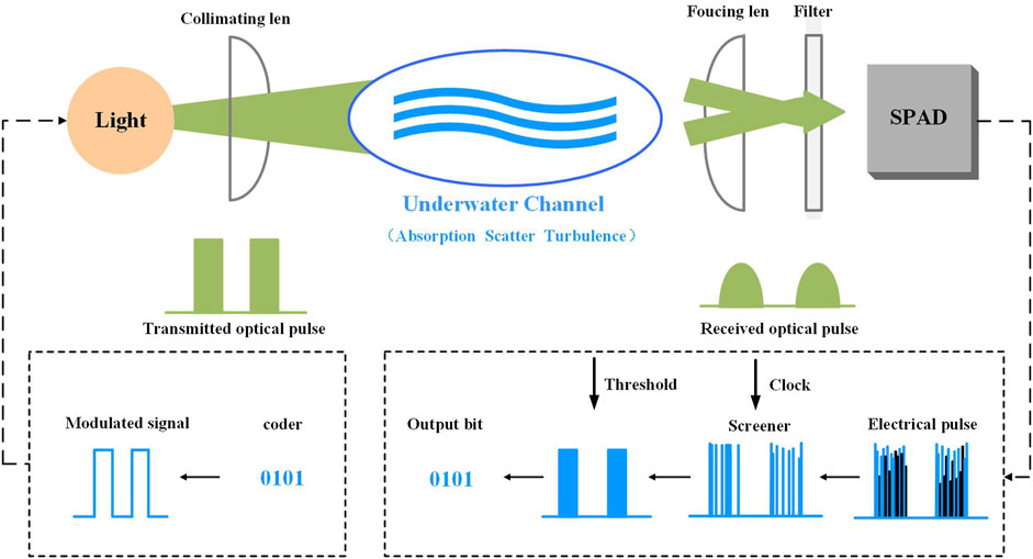
FIGURE 1. The conceptual diagram of underwater photon-counting communication (UPCC) system. The system consists of two parts: intensity modulation and direct detection photon-counting receiver. The information bits are encoded and modulated into an optical signal; the optical signal is transmitted through the underwater channel, and only a few photons are received. The photons are then received by a single-photon avalanche diode (SPAD) and converted into electrical pulses that are synchronized, counted, and demodulated to recover the original bits.
The Modulation Schemes for OOK and Digital Pulse Modulations
In the UPCC system with IM/DD, OOK and PPM are the commonly used IM schemes. Compared with OOK modulation, PPM has higher power utilization efficiency but lower bandwidth utilization [22], which is often used in photon-counting communication systems to improve sensitivity. To optimize the bandwidth utilization of PPM, many digital pulse modulation schemes have been developed, such as DPPM, DPIM, DPIM, and DH-PIM. OOK modulation uses one optical pulse to represent a 1-bit signal, whereas digital pulse modulations decompose a signal symbol into multiple time slots; the position of the optical pulse within a symbol is used to represent multiple bits, with the remaining slots being empty. DPPM removes the redundant time slots that exist in PPM. For DPIM, each symbol begins with a slot-duration pulse, followed by a series of empty data slots, the number of which depends on the decimal value of the encoded M-bit data stream. To mitigate intersymbol interference degradation of the signal, a guard slot consisting of one or more empty slots is added after the pulse. Compared with PPM, DPPM, and DPIM, DH-PIM not only removes the redundant time slots that follow the pulse in the PPM and but also reduces the average symbol length compared with DPIM. The time-domain waveforms of OOK and several digital pulse modulation schemes are shown in Figure 2 [23]. As shown in the figure, to have the same data throughout as OOK, the slot duration time
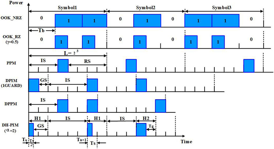
FIGURE 2. Time waveforms for OOK, DPIM, PPM, DPIM, DPPM, DH_PIM (
For IMs, the digital signal is loaded into the carrier wave by modulating the intensity and position of a light wave. The biggest difference between these modulations is the number of slots in a single symbol, which influences directly the transmit optical power per ON slot. The more slots, the higher transmit optical power per ON slot when the average optical transmit power keeps fixed; the relation between the mean transmit power per symbol and optical power per ON slot can be expressed as
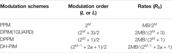
TABLE 1. The modulation orders and the communication rates for different modulation schemes under a given B and M [23].
Underwater Channel Model
The absorption and scattering of the light by the seawater will cause the attenuation of the energy of the optical signal, especially when the turbidity of seawater is high; the signal quality will also deteriorate. The extinction coefficient
In the formula, the units of the three parameters are
The coefficients
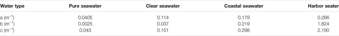
TABLE 2. Absorption, scattering, and extinction coefficient for the Pure seawater and three Petzold water types.
Many channel models of UWOC can be obtained from [25, 28–31]. When an optical beam is transmitting in the pure seawater and clear seawater, the temporal spread of the optical pulse can be neglected. Geometric Beer’s Law (GBL) can be applied to these two water types to calculate the geometric attenuation since the beam spreading and alignment error [32]. In this article, we consider the line-of-sight communication link model. In this scenario, the light beam is directed from a transmitter into a receiver; both telescope gain and loss are taken into account, the optical signal reaching the receiver is obtained by [25]:
where
Underwater Turbulence Model
In the practical application of UWOC, considering aperture average effect, received optical power under the influence of underwater optical turbulence can be represented by log-normal distribution from weak to strong turbulence condition, which has been validated by a large number of field experiments. The probability density function (PDF)
where
where
where
SPAD Photon-Counting Receiver Model
When the UWOC works, assume the average signal photon rate reaching the front end of the detector is the constant
where
where h is the Planck constant, and
We assume the sampling rate of SPAD is very high compared with the dead time so that the counting losses due to finite sampling rate can be negligible. If the dead time of SPAD is the constant
Bit Error Ratio Calculation
For OOK modulation, based on the principle of threshold test, the bit error ratio (BER) can be given as [37]:
where
For PPM, DPIM, DMMP, and DH-PIM symbol, the symbol error ratio (SER) for a continuous output L-order digital pulse modulation signal is [38]:
The SER can be converted into BER by:
Based on the principle of minimum error probability [39], by solving the following Eq. 13, we can get the optimum threshold
where P(0) and P(1) are a prior probability of time slot detection.
Numerical Results and Discussion
In this research, with the assumption of negligible delay spread, based on the GBL model and SPAD photon-counting receiver model, we establish the relationship between the BER and attenuation length on the underwater wireless UPCC system in the pure seawater. The effect of M on various IM schemes is also investigated. The parameters of the UWOC system are listed in Table 3. In the following discussion, the specifications of the SPCM20A from Thorlabs [40] have been applied to this simulation. The values of other parameters characterize the classical channel of the UWOC system. According to [41], the attenuation length, which is defined as the multiple of the transmission distance and attenuation coefficient, is used to represent the link transmission distance to remove the ambiguity of distance and various water conditions. In addition, with the assumption of negligible slot time delay spread, the degradation of signal bandwidth and the intersymbol caused by channel transmission can be ignored. Therefore, the mathematical relationship between data rate and modulation bandwidth in Table 1 [23] can be used in this article.
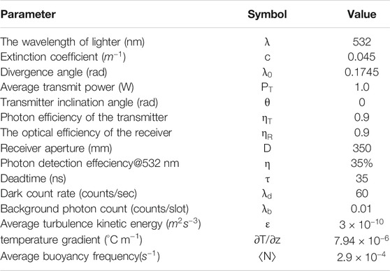
TABLE 3. Parameters of UPCC system.
On the one hand, BERs for OOK, PPM, DPIM, DPPM, and DH-PIM as the function of attenuation length when
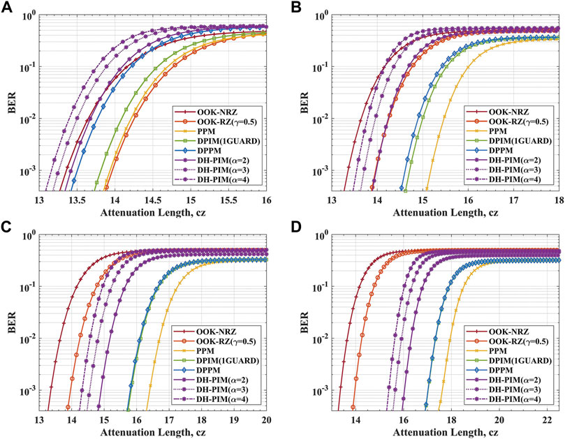
FIGURE 3. The BER against the attenuation length for UPCC system in the pure seawater channel when
DH-PIM is one of the digital pulse modulations. Compared with PPM and PIM, DH_PIM not only removes the redundant time slots that follow the pulse in the PPM but also reduces the average symbol length compared with PIM [46]. In DH-PIM, the nth symbol starts with a header duration and follows with a sequence of
As the results of the above analysis, increasing the value of the M for the same modulation bandwidth significantly improves the power utilization of the digital pulse modulation so that the attenuation length of the system increases. However, M is related to the bandwidth utilization, which decides the transmission rate of a communication system. The higher transmission rate means the higher bandwidth utilization for the same M. We limit the BER simulation results to below the FEC limit; the transmission rates and attenuation lengths of a system for DH-PIM, PPM, DPPM, and DPIM under the different M are shown in Figure 4. This figure clearly shows the trade-off between transmission rate and attenuation length. For PPM, DPIM, and DPPM systems, the attenuation length increases with M, but the transmission rate decreases accordingly. This is because for digital pulse modulation schemes, when the modulation bandwidth is fixed, the power utilization is proportional to the value of M, and the bandwidth utilization is inversely proportional to M. For DPIM with a guard slot, the transmission rate and attenuation length of the system are almost the same for M = 6 and M = 8. Comparing the performance of DPIM with a guard slot and PPM, the system for the PPM scheme can achieve a longer transmission length, but the transmission rate is lower than the DPIM system at a certain value of M. For DH-PIM, the bandwidth utilization efficiency is the highest of all digital pulse modulations, and it is evident that there is the highest point of transmission rate for DH-PIM when M = 4.
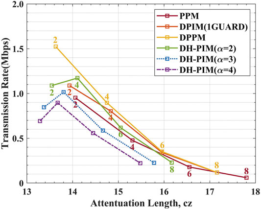
FIGURE 4. The rate versus the attenuation length for BER is
On the other hand, to do a fair comparison between the different IM schemes, the communication performance of the UPCC system under the various IM schemes is compared when the data rate and average transmit optical power are fixed. As shown in Figure 5, setting the bit rate to 50 Kbps, the value of M is 2, 4, 6, 8 in sequence. When M = 2 and BER is the FEC limit, the minimum attenuation length that DH-PIM (
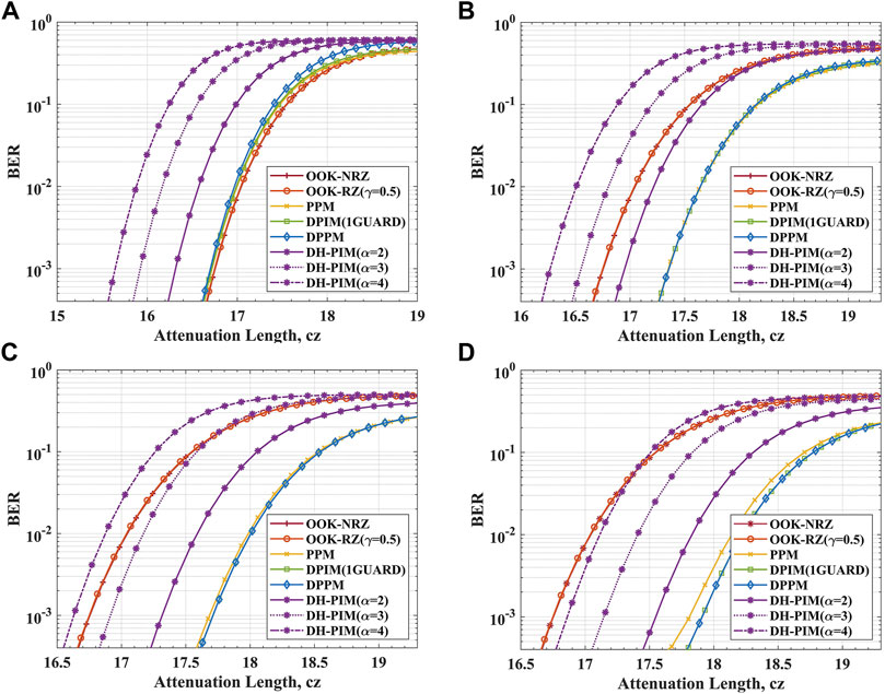
FIGURE 5. The BER against the attenuation length for UPCC system in the pure seawater channel when the bit rate is 50 Kbps. The communication performance of UPCC systems under several modulation schemes when (A) M = 2 and (B) M = 4, (C) M = 6, (D) M = 8, respectively.
Conclusion
In this article, a UPCC system model based on IM and DD photon counting reception techniques is built. The article compares the variation of BER with a transmission distance of communication system for OOK, PPM, DPIM, DPPM, and DH-PIM under the same modulation bandwidth. From our analysis, we conclude that the PPM has the longest transmission distance at the same BER when M > 2, but the lowest communication rate. Transmission distance gets farther, and the communication rate gets lower as M increases. In addition, the same analysis is done under a fixed communication rate. It is concluded that the DPPM and DPIM have the optimum communication performance at the same communication rate when M = 8. As the modulation bandwidth is lower and the time slot time is longer for DPPM and DPIM than PPM when the communication rate is the same, long slot time will help reduce the difficulty of signal synchronization and hence the complexity of the underwater photon counting system. The simulation and analysis in this article are based on published theoretical models, and the results concluded can be referenced for real transmission communication.
Data Availability Statement
The original contributions presented in the study are included in the article/supplementary material, further inquiries can be directed to the corresponding authors.
Author Contributions
XX, WW, and XH conceived the idea of the study; XH and PL analyzed the data, interpreted the results, and wrote the article; all authors discussed the results and revised the manuscript.
Funding
Program Name: Deep-sea Omni-directional High-speed Long-distance Optical. (Strategic Pioneer Science and Technology Special Project of Chinese Academy of Sciences(Class A)) Funder: Chinese Academy of Sciences Grant number: XDA22030203 Program Name: Ministry of Science and Technology Key R&D Program. Grant number: 2018YFC0307904.
Conflict of Interest
The authors declare that the research was conducted in the absence of any commercial or financial relationships that could be construed as a potential conflict of interest.
Publisher’s Note
All claims expressed in this article are solely those of the authors and do not necessarily represent those of their affiliated organizations, or those of the publisher, the editors and the reviewers. Any product that may be evaluated in this article, or claim that may be made by its manufacturer, is not guaranteed or endorsed by the publisher.
References
1. Qiao S, Ma Y, He Y, Patimisco P, Sampaolo A, Spagnolo V. Ppt Level Carbon Monoxide Detection Based on Light-Induced Thermoelastic Spectroscopy Exploring Custom Quartz Tuning forks and a Mid-infrared QCL. Opt Express (2021) 29(16):25100–8. doi:10.1364/OE.434128
2. Gao D, Xie Z, Ma R, Wang W, Bai Z, Jia S, et al. Analysis of the Current Situation and Trends in the Development of Satellite Laser Communications (Invited). J Photon (2021) 50(04):9–29. doi:10.3788/gzxb20215004.0406001
3. Lang Z, Qiao S, He Y, Ma Y. Quartz Tuning fork-based Demodulation of an Acoustic Signal Induced by Photo-Thermo-Elastic Energy Conversion. Photoacoustics (2021) 22:100272. doi:10.1016/j.pacs.2021.100272
4. Ali MF, Jayakody DNK, Chursin YA, Affes S, Dmitry S. Recent Advances and Future Directions on Underwater Wireless Communications. Arch Computat Methods Eng (2020) 27(5):1379–412. doi:10.1007/s11831-019-09354-8
5. Kodama T, Arai K, Nagata K, Nakamura K, Hanawa M. Underwater Wireless Optical Access Network with OFDM/SBMA System: Concept and Demonstration. In: Proceeding of the 2019 24th OptoElectronics and Communications Conference (OECC) and 2019 International Conference on Photonics in Switching and Computing (PSC); 2019 July 7-11; Fukuoka, Japan. IEEE (2019). p. 18957302. doi:10.23919/ps.2019.8817754
6. Ooi BS, Kong M, Ng TK. Underwater Wireless Optical Communications: Opportunity, Challenges and Future Prospects Commentary on “Recent Progress in and Perspectives of Underwater Wireless Optical Communication”. Prog Quan Electronics (2020) 73:100275. doi:10.1016/j.pquantelec.2020.100275
7. Duntley SQ. Light in the Sea*. J Opt Soc Am (1963) 53(2):214–33. doi:10.1093/icb/26.2.38910.1364/josa.53.000214
8. Sun X, Kang CH, Kong M, Alkhazragi O, Guo Y, Ouhssain M, et al. A Review on Practical Considerations and Solutions in Underwater Wireless Optical Communication. J Lightwave Technol (2020) 38(2):421–31. doi:10.1109/jlt.2019.2960131
9. Saeed N, Celik A, Al-Naffouri TY, Alouini M-S. Underwater Optical Wireless Communications, Networking, and Localization: A Survey. Ad Hoc Networks (2019) 94:101935. doi:10.1016/j.adhoc.2019.101935
10. Matthews W, Ahmed Z, Ali W, Collins S. A 3.45 Gigabits/s SiPM-Based OOK VLC Receiver. IEEE Photon Technol Lett (2021) 33(10):487–90. doi:10.1109/LPT.2021.3069802
11. Hanson F, Radic S. High Bandwidth Underwater Optical Communication. Appl Opt (2008) 47(2):277–83. doi:10.1364/AO.47.000277
12. Du J, Wang Y, Fei C, Chen R, Zhang G, Hong X, et al. Experimental Demonstration of 50-M/5-Gbps Underwater Optical Wireless Communication with Low-Complexity Chaotic Encryption. Opt Express (2021) 29(2):783–96. doi:10.1364/OE.416117
13. Tsai W-S, Lu H-H, Wu H-W, Tu S-C, Huang Y-C, Xie J-Y, et al. 500 Gb/s PAM4 FSO-UWOC Convergent System with a R/G/B Five-Wavelength Polarization-Multiplexing Scheme. IEEE Access (2020) 8:16913–21. doi:10.1109/ACCESS.2020.2967856
14. Hiskett PA, Struthers RA, Tatton R, Lamb R. A Photon-Counting Optical Communication System for Underwater Data Transfer. In: Proceeding of the Electro-Optical Remote Sensing, Photonic Technologies, and Applications VI; 2021 Nov. 19; Edinburgh, United Kingdom. Edinburgh, UK: International Society for Optics and Photonics (2012). p. 854214. doi:10.1117/12.974938
15. Mao T, Wang Z, Wang Q. Receiver Design for SPAD-Based VLC Systems under Poisson-Gaussian Mixed Noise Model. Opt Express (2017) 25(2):799–809. doi:10.1364/OE.25.000799
16. Wang C, Yu H-Y, Zhu Y-J. A Long Distance Underwater Visible Light Communication System with Single Photon Avalanche Diode. IEEE Photon J. (2016) 8(5):1–11. doi:10.1109/JPHOT.2016.2602330
17. Sarbazi E, Safari M, Haas H. The Bit Error Performance and Information Transfer Rate of SPAD Array Optical Receivers. IEEE Trans Commun (2020) 68(9):5689–705. doi:10.1109/TCOMM.2020.2993374
18. Rao HG, DeVoe CE, Fletcher AS, Gaschits ID, Hakimi F, Hamilton SA. A Burst-Mode Photon Counting Receiver with Automatic Channel Estimation and Bit Rate Detection. In: SPIE Proceedings Free-Space Laser Communication and Atmospheric Propagation XXVIII; 2016 April 13; San Franciso, California, United States. San Franciso, CA: SPIE (2016). p. 9739. International Society for Optics and Photonics. doi:10.1117/12.2222885
19. Hu S, Mi L, Zhou T, Chen W. 3588 Attenuation Lengths and 332 Bits/photon Underwater Optical Wireless Communication Based on Photon-Counting Receiver with 256-PPM. Opt Express (2018) 26(17):21685–99. doi:10.1364/oe.26.021685
20. Chen Z, Tang X, Sun C, Li Z, Shi W, Wang H, et al. Experimental Demonstration of over 14 AL Underwater Wireless Optical Communication. IEEE Photon Technol Lett (2021) 33(4):173–6. doi:10.1109/LPT.2020.3048786
21. Gabriel C, Khalighi M-A, Bourennane S, Léon P, Rigaud V. Investigation of Suitable Modulation Techniques for Underwater Wireless Optical Communication. In: Proceeding of the 2012 International Workshop on Optical Wireless Communications (IWOW); 2012 Oct. 22-22; Pisa, Italy. IEEE (2012). p. 113–4. doi:10.1109/IWOW.2012.6349691
22. Wang X, Wang Y, Yao Z, Chen X, Zhu X, Zhang X. Timing Offset Estimation of PPM Signal for Deep Space Optical Communications. In: Signal and Information Processing, Networking and Computers: Proceedings of the 6th International Conference on Signal and Information Processing, Networking and Computers (ICSINC). Xi'an China: Springer Nature (2020). p. 444–52. doi:10.1007/978-981-15-4163-6_53
23. Ghassemlooy Z, Popoola W, Rajbhandari S. Optical Wireless Communications: System and Channel Modelling with Matlab®. New York, USA: CRC Press (2019). p. 204–309.
24. Sato K, Asatani K. Speckle Noise Reduction in Fiber Optic Analog Video Transmission Using Semiconductor Laser Diodes. IEEE Trans Commun (1981) 29(7):1017–24. doi:10.1109/TCOM.1981.1095084
25. Gabriel C, Khalighi M, Bourennane S, Leon P, Rigaud V. Channel Modeling for Underwater Optical Communication. In: Proceeding of the 2011 IEEE GLOBECOM Workshops (GC Wkshps); 5-9 Dec. 2011; Houston, Tx USA. IEEE (2011). p. 6162571. doi:10.1109/GLOCOMW.2011.6162571
26. Arnon S, Kedar D. Non-line-of-sight Underwater Optical Wireless Communication Network. J Opt Soc Am A (2009) 26(3):530–9. doi:10.1364/JOSAA.26.000530
27. Cochenour BM, Mullen LJ, Laux AE. Characterization of the Beam-Spread Function for Underwater Wireless Optical Communications Links. IEEE J Oceanic Eng (2008) 33(4):513–21. doi:10.1109/JOE.2008.2005341
28. Tang S, Dong Y, Zhang X. Impulse Response Modeling for Underwater Wireless Optical Communication Links. IEEE Trans Commun (2014) 62(1):226–34. doi:10.1109/TCOMM.2013.120713.130199
29. Akhoundi F, Salehi JA, Tashakori A. Cellular Underwater Wireless Optical CDMA Network: Performance Analysis and Implementation Concepts. IEEE Trans Commun (2015) 63:882–91. doi:10.1109/TCOMM.2015.2400441
30. Zhang H, Dong Y. Impulse Response Modeling for General Underwater Wireless Optical MIMO Links. IEEE Commun Mag (2016) 54:56–61. doi:10.1109/MCOM.2016.7402261
31. Li Y, Leeson MS, Li X. Impulse Response Modeling for Underwater Optical Wireless Channels. Appl Opt (2018) 57(17):4815–23. doi:10.1364/AO.57.004815
32. Huang J, Wen G, Dai J, Zhang L, Wang J. Channel Model and Performance Analysis of Long-Range Deep Sea Wireless Photon-Counting Communication. Opt Commun (2020) 473:125989. doi:10.1016/j.optcom.2020.125989
33. Andrews LC, Phillips RL, Hopen CY. Laser Beam Scintillation with Applications. Bellingham, Washington USA: SPIE press (2001). p. 112–5.
34. Cheng X, Qu F, Yang L. Single Carrier FDMA over Underwater Acoustic Channels. In: Proceeding of the 2011 6th International ICST Conference on Communications and Networking in China (CHINACOM); 17-19 Aug. 2011; Harbin. IEEE (2011). p. 6158311.
35. Weng Y, Guo Y, Alkhazragi O, Ng TK, Guo J-H, Ooi BS. Impact of Turbulent-Flow-Induced Scintillation on Deep-Ocean Wireless Optical Communication. J Lightwave Technol (2019) 37(19):5083–90. doi:10.1109/JLT.2019.2928465
36. Sarbazi E, Safari M, Haas H. Statistical Modeling of Single-Photon Avalanche Diode Receivers for Optical Wireless Communications. IEEE Trans Commun (2018) 66(9):4043–58. doi:10.1109/TCOMM.2018.2822815
37. Popoola W, Ghassemlooy Z, Awan MS, Leitgeb E. Atmospheric Channel Effects on Terrestrial Free Space Optical Communication Links3rd International Conference on Computers and Artificial Intelligence (ECAI 2009). Pites ti: Citeseer (2009).
39. Kay SM. Fundamentals of Statistical Signal Processing. Detection Theory, Volume Ii. New York: Printice Hall PTR (1998). p. 435–7.
40.Thorlabs. V21 Catalog (2011). Available at: https://www.thorlabs.com/NewGroupPage9_PF.cfm?ObjectGr oup_ID=5255 (Accessed September 15, 2021).
41. Zhang L, Tang X, Sun C, Chen Z, Li Z, Wang H, et al. Over 10 Attenuation Length Gigabits Per Second Underwater Wireless Optical Communication Using a Silicon Photomultiplier (SiPM) Based Receiver. Opt Express (2020) 28(17):24968–80. doi:10.1364/OE.397942
42. Wang J, Lu C, Li S, Xu Z. 100 M/500 Mbps Underwater Optical Wireless Communication Using an NRZ-OOK Modulated 520 Nm Laser Diode. Opt Express (2019) 27(9):12171–81. doi:10.1364/OE.27.012171
43. Tang X, Kumar R, Sun C, Zhang L, Chen Z, Jiang R, et al. Towards Underwater Coherent Optical Wireless Communications Using a Simplified Detection Scheme. Opt Express (2021) 29(13):19340–51. doi:10.1364/OE.426820
44. Fei C, Hong X, Zhang G, Du J, Gong Y, Evans J, et al. 166 Gbps Data Rate for Underwater Wireless Optical Transmission with Single Laser Diode Achieved with Discrete Multi-Tone and post Nonlinear Equalization. Opt Express (2018) 26(26):34060–9. doi:10.1364/OE.26.034060
45.ITU. ITU-T Fecfhb-rDss (ITU, 2004) (2021). Available: http://www.itu.int/rec/T-REC-G.97 5.1-200402-I/en (Accessed December 15, 2021).
Keywords: underwater wireless optical communication (UWOC), intensity modulation (IM), direct detection (DD), digital pulse modulation, photon counting, channel model
Citation: Han X, Li P, Chang C, Gao D, Zhang D, Liao P, Wang W and Xie X (2022) A Comprehensive Comparison and Analysis of Several Intensity Modulations Based on the Underwater Photon-Counting Communication System. Front. Phys. 9:815343. doi: 10.3389/fphy.2021.815343
Received: 15 November 2021; Accepted: 14 December 2021;
Published: 31 January 2022.
Edited by:
Yufei Ma, Harbin Institute of Technology, ChinaReviewed by:
Heping Zeng, East China Normal University, ChinaShuangyi Yan, University of Bristol, United Kingdom
Copyright © 2022 Han, Li, Chang, Gao, Zhang, Liao, Wang and Xie. This is an open-access article distributed under the terms of the Creative Commons Attribution License (CC BY). The use, distribution or reproduction in other forums is permitted, provided the original author(s) and the copyright owner(s) are credited and that the original publication in this journal is cited, in accordance with accepted academic practice. No use, distribution or reproduction is permitted which does not comply with these terms.
*Correspondence: Wei Wang, wangwei2012@opt.ac.cn; Xiaoping Xie, xxp@opt.ac.cn