Dual Hydrogen- and Oxygen-Transport Membrane Reactor for Solar-Driven Syngas Production
 Maria Tou
  Brendan Bulfin
- Department of Mechanical and Process Engineering, ETH Zürich, Zürich, Switzerland
A novel thermochemical dual-membrane reactor is considered with the goal of efficiently converting CO2 to fuels using concentrated solar energy as the process heat source. In contrast to the temperature-swing redox cycle, in this isothermal system the thermolysis of H2O at above 1,800 K is assisted by removal of O2 across an oxygen-permeable membrane and of H2 across a hydrogen-permeable membrane. The latter is consumed by a stream of CO2 via the reverse water-gas shift reaction to re-form H2O and continuously generate CO. The net reaction is the splitting of CO2 to CO and
Introduction
Liquid hydrocarbon fuels are convenient energy carriers because of their high volumetric energy density, storability, and transportability with the existing global infrastructure. To that end, the formation of CO and H2 (syngas) would be valuable as a feedstock for several established liquid fuel synthesis processes, such as Fischer-Tropsch or methanol synthesis. Research on various solar-driven approaches to convert CO2 and H2O to syngas has grown steadily as calls to reduce carbon emissions in the transportation and energy sector have intensified (Lewis, 2016). While solar photovoltaics combined with electrolysis offers one commercialized option for producing H2 from H2O, an economically competitive solar technology to liquid fuels production from H2O and CO2 is still missing (Tuller, 2015).
The solar thermochemical approach to dissociate CO2 and H2O is promising because it utilizes the entire solar spectrum in the form of high-temperature process heat and, thus, enables thermodynamically favorable reactions and the potential of reaching high energy conversion efficiencies (Romero and Steinfeld, 2012). Specifically, a thermochemical membrane reactor suggests a path to isothermal and continuous splitting of CO2 and H2O, reactions described by
In membrane-assisted thermolysis, one of the products is removed across a selective membrane to boost reaction conversion and prevent recombination. The idea to apply this concept to solar fuel production was pioneered by Fletcher and co-workers in the late 1970s (Fletcher and Moen, 1977; Noring et al., 1981). The first studies on solar thermal membrane reactors were theoretical in nature and focused on splitting H2O (Fletcher and Moen, 1977; Noring et al., 1981; Kogan, 1997), and the vast majority of previous work has focused on oxygen-transport membranes (Franca et al., 2012; Muhich et al., 2013; Wang et al., 2015). This is because high-temperature oxygen-ion conducting materials are reasonably common, and their development has been propelled by applications in sensors, air separation (Sunarso et al., 2008; Geffroy et al., 2013), and solid-oxide fuel cells (Kharton et al., 2004; Garagounis et al., 2011). Recently, we have experimentally demonstrated the use of ceria-based oxygen-transport membranes in a solar cavity-receiver splitting CO2 (Tou et al., 2017), and co-splitting CO2 and H2O simultaneously (Tou et al., 2019). However, the extent of H2O and CO2 thermolysis, even when enhanced by an oxygen-transport membrane, is impractically low at the required operating temperatures, typically in the range 1,500–2,000 K (Ermanoski et al., 2014; Li et al., 2019). For example, at a temperature of 2,000 K and a pressure of 1 bar, with oxygen extracted at a partial pressure of 3 × 10⁻⁵ bar, the thermodynamic limit for conversion of H2O to H2 is still only 5%.
The development of suitable hydrogen-permeable materials could improve the prospects of membrane reactor technology. In a 1981 study by Noring et al. (1981), a water-splitting reactor with two membranes, one each for oxygen and hydrogen removal was proposed. This combination significantly increases the driving force for thermolysis of H2O and thus the theoretical fuel yield. Another benefit is the 100% purity of each product stream provided both membranes are perfectly selective. Nevertheless, the idea remained dormant for over three decades because the state-of-the-art could not supply stable materials at the temperatures required. Noring et al.’s concept applies uniquely to H2O thermolysis because there has not been any research on CO-selective membranes that operate at and above 1,500 K to the knowledge of the authors. However, such a dual-membrane reactor (DMR) could still be useful for CO2 splitting. The reactor system proposed by Noring et al. (1981) needs only a minor but nevertheless crucial modification: a feed of CO2 introduced to the hydrogen chamber. Then, in addition to the thermolysis of H2O in the steam chamber, CO2 can react simultaneously with H2 via the reverse water-gas shift (RWGS) reaction to produce CO:
Both reactions in Eqs 2 and 3 are enhanced by the transfer of H2 across the membrane, and, in turn, drive further transport as they proceed. The net reaction is CO2 splitting, as given in Eq. 1. To the authors’ knowledge, such a membrane reactor concept is novel and could potentially become a breakthrough in this emerging field. Here we present a comparative thermodynamic analysis to understand how this DMR could work and to assess its performance potential. We also discuss the material challenges which researchers face to test this concept experimentally.
We select three representative configurations of a membrane reactor that could achieve the net reduction of CO2: the DMR and two reference systems with a single membrane. For the sake of elucidating the key thermodynamics, the configurations are set up as three simple thought experiments as shown in Figure 1. In all cases, a closed volume is divided into chambers by semi-permeable boundaries—the membranes. Each chamber is filled with an initial amount of gases at set temperature T and pressure p. The system is then allowed to equilibrate at constant T and p. The walls are movable such that volumes can adjust freely as the number of molecules in each chamber changes (indicated by the spring symbol in Figure 1).
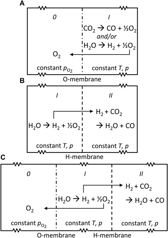
FIGURE 1. Schematics of three configurations for the net thermochemical splitting of CO2 to CO and O2: (A) oxygen-membrane reactor, (B) hydrogen-membrane reactor, and (C) dual-membrane reactor. A spring symbol is used to indicate the free adjustment of volume in each chamber to maintain constant p.
The first configuration is depicted in Figure 1A. Let’s call the system the oxygen-membrane reactor (OMR). The simplest configuration of the three to be analyzed, the OMR contains two chambers, 0 and I, separated by an oxygen-permeable membrane. In chamber 0 a constant low value of
The second configuration, shown in Figure 1B, follows the same principles as the first. Let’s call it the hydrogen-membrane reactor (HMR). The HMR consists of two chambers, I and II, separated by a hydrogen-permeable membrane. Initially, chamber I contains H2O and chamber II contains CO2. T and p are controlled in each chamber. At these conditions, H2O undergoes thermolysis like in the OMR. In this case, the equilibrium is shifted by the removal of H2 as it diffuses to chamber II. Unlike the OMR,
The third configuration combines the OMR and HMR concepts to harness a dual driving force. The DMR shown in Figure 1C has three chambers, 0, I, and II, demarcated by two membranes, one oxygen-selective and one hydrogen-selective. Each component behaves like its counterpart in the previous two configurations. However, now the thermolysis of H2O in chamber I is enhanced by both the O2 removal into chamber 0 and H2 removal into chamber II, driven by differences in partial pressure of the respective species. The RWGS reaction consumes H2 from chamber I to drive formation of CO in chamber II. At equilibrium,
Thermodynamic Model
The thermodynamic limits of the membrane reactor are governed by mass conservation and equilibrium relations, which, in turn, are dependent on the initial feed, temperature, total chamber pressures, and partial pressures of the components. We assume:
• closed system
• constant and uniform temperature and pressure in each chamber
• ideal gases
• well-mixed reactor chambers
• perfectly selective membranes
• thermodynamic equilibrium
The system as a whole is closed and at constant temperature and pressure, so that equilibrium will be the state with minimum Gibbs free energy, subject to mass balance constraints which are set by the initial conditions and the allowed chemical reactions. The Gibbs free energy is given by G = ∑μini, where μi and ni are the chemical potential and number of moles of species i. Because the system is isothermal and the species are modeled as ideal gases, we can use
where
Therefore, a second approach is implemented using thermodynamic software to account for all reactions possible starting from the initial composition. Cantera, a toolkit for chemical kinetics, thermodynamics, and transport problems, and its GRI-Mech 3.0 database (consisting of 53 species and 325 reactions detailing the natural gas combustion mechanism, including thermodynamic data for all species in the membrane reactor system) is called from Python and used for equilibrium composition calculations (Goodwin et al., 2009). To find the minimum Gibbs free energy we allow each chamber to go to chemical equilibrium separately, satisfying ΔG ≤ 0, and then check if there is a difference in chemical potential (partial pressure) of hydrogen across the hydrogen membrane and/or of oxygen across the oxygen membrane. If there is a difference, some of the membrane selective species Δni is transferred from higher to lower chemical potential so that ΔG = ΔμiΔni ≤ 0, where Δμi is the drop in chemical potential of the hydrogen or oxygen across the membrane. Each chamber is again allowed to go to equilibrium separately, and the process is repeated iteratively. In this way, we can converge on equilibrium in a finite number of steps, all of which satisfy ΔG ≤ 0, so that the entire process can proceed spontaneously.
Because the OMR and HMR serve as references for the DMR, and to avoid repetition, the OMR and HMR models are described in Supplementary Figures S1,S2 and Supplementary Tables S1,S2 and only the DMR model is detailed here. The model inputs are T, p,
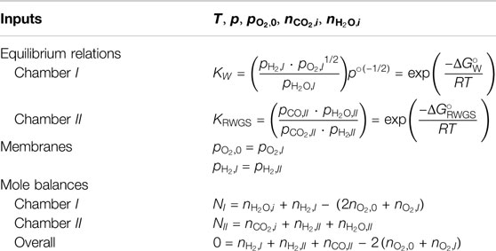
TABLE 1. System of equations for the dual-membrane reactor.
Figure 2 depicts the DMR model flow. Because there are two membranes, two sets of nested iterations are needed to determine the equilibrium state for the entire system. First, the reaction conditions and the initial feed are defined. Chambers I and II are equilibrated and the resulting
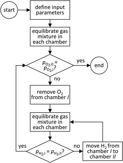
FIGURE 2. A flowsheet illustrating the logic applied in the dual-membrane reactor equilibrium model.
The model outputs are the equilibrium mole amounts of every species in each chamber, from which performance indicators can be calculated. The first is the mole fraction of fuel in the product mixture, which for the HMR and DMR is given by
For the HMR and DMR, xfuel indicates the purity of the fuel produced, after condensation of the steam out of the syngas. For the OMR the fuel fraction is simply given by the mole fraction of CO or H2, (e.g.,
In the DMR, both H2 and O2 are removed from chamber I and conversion of H2O could theoretically reach 100%. This implies that the number of moles in chamber I could approach zero. Because values close to zero cause numerical issues, a tolerance was set in the model to avoid infinite iteration. Another consequence of full conversion of H2O is that it could limit the RWGS reaction in chamber II. That is, the equilibrium state has been reached for the given conditions and initial feed, but if there were additional H2O relative to the CO2 available, CO2 would react further, and a different equilibrium composition would result. This means that there exists a minimum H2O:CO2 feed ratio to reach “unconstrained” equilibrium in the DMR. This dependence on H2O:CO2 is shown in Supplementary Figure S6.
Theoretical Energy Efficiency Analysis
Another critical performance indicator is the solar-to-fuel energy efficiency of the reactor, ηsolar-to-fuel. Here, ηsolar-to-fuel is defined as the heating value of the fuel produced divided by the total heat input,
where the numerator is calculated using the appropriate higher heating value based on the amounts of CO and H2 produced at equilibrium, and Qin represents all heat and work heat-equivalents entering the solar reactor cavity. To define Qin, a few assumptions must be made about the process, which is diagrammed with all possible process units in Figure 3. Thus, the solar-to-fuel energy efficiency is not a pure thermodynamic property. First, only solar radiation entering through the cavity’s aperture is accounted for. That is, heliostat field losses are not included. The solar cavity-receiver is assumed to be a perfectly insulated blackbody absorber. Re-radiation losses from the cavity are included, but conductive and convective losses are neglected. It is assumed that the membrane reactor is operated in continuous parallel-flow mode and heat recovery from the exiting gases pre-heats the incoming streams. Low
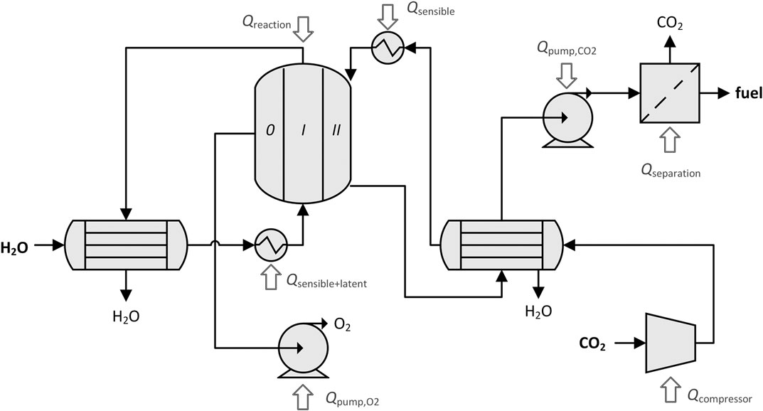
FIGURE 3. Process diagram of the dual-membrane reactor including process units and heat inputs. Different subsets of these process units are applicable for different membrane configurations and operating conditions.
The cavity absorption efficiency, ηabs, is only applied on the inputs added to the system in the form of concentrated solar heat: reaction enthalpy, Qreaction; sensible heating of gases, Qsensible; and latent heat of vaporization of steam, Qlatent. The other inputs are work penalties converted to heat: heat equivalent to pump O2 out of chamber 0,
As a blackbody absorber, re-radiation from the solar cavity is characterized by (Steinfeld and Palumbo, 2001):
where σ is the Stefan-Boltzmann constant, I is the direct normal solar irradiation (DNI = 1 kW/m2), and C is the solar concentration ratio. The reaction enthalpy is calculated for each reaction as
where χfeed and nfeed are the conversion and the initial number of moles, respectively, νi is the stoichiometric coefficient of species i, and hf,i is the molar heat of formation of species i at T. The feed species refers to CO2 or H2O, depending on the reaction. The sum of Qreaction for each reaction in the system defines the total. Without heat recovery, heating is required to bring the feed species from ambient T0 to reaction temperature T. The sensible portion is the total change in enthalpy less the latent heat of vaporization, if applicable:
For H2O streams, the latent heat requirement is then:
With heat recovery, some fraction of the heat available in the outlet streams preheats the inlet to Tx, as determined by the heat recovery efficiency (Bader et al., 2013; Ermanoski et al., 2014; Venstrom et al., 2014; Bulfin et al., 2015):
where the denominator sums the change in enthalpy of each species in the outlet stream. Then, the sensible heating requirement is reduced to
For an H2O stream, we assume that the heat exchanger is used for latent heating first, and so this modification of Qsensible only applies if
In general, a heat input may not be negative, it may only be reduced to zero. Because the DMR has two gas streams, there are two possible arrangements for the two heat exchangers. In one, each outlet stream preheats its own inlet, as shown in Figure 3. In the other, streams are crossed in the heat exchangers so that one outlet stream preheats the opposite inlet and vice versa. Depending on the operating conditions, one of the arrangements may be favorable to maximize the amount of recovered heat.
The magnitude of the energy penalties in Qin depend strongly on the assumptions made respecting the efficiency of their processes. Therefore, two cases are presented: the ideal case marking the thermodynamic limit and the more realistic case considering real processes and empirically observed efficiencies.
For vacuum pumping of a chamber to vacuum pressures, as done to control
where npumped is the amount of gas pulled through the vacuum pump (
where ηpump is determined by an envelope function fit to the empirical efficiency of vacuum pumps reported by Brendelberger et al. (2017). If CO2 is fed at elevated pressure, the idealized heat equivalent for the pumping work is based on isentropic compression, because most compressors in industry are designed to run adiabatically (Campbell, 2014):
where Cp is the heat capacity of CO2 and R is the ideal gas constant.
Thermolysis reactions suffer from low molar conversions at insufficiently high T. Therefore, the gas mixture exiting the reactor may need purification. H2O can be separated via condensation at low T and requires no additional work. CO2 removal, on the other hand, requires an additional process. The minimum work to separate CO2 from fuel in the product gas mixture is the difference in Gibbs free energy of mixing between the reactor outlet composition and the desired purity. Assuming any H2O present in the product stream is previously removed, the gas mixture is treated as a binary mixture of fuel and CO2:
where xfuel and N are the mole fraction of fuel and total number of moles in the dehydrated product, respectively, and
It is worth noting that the heating value of CO is 283 kJ/mol, which is the same order of magnitude as qscrubber. Thus, Qseparation,real can already be anticipated to have a large impact on ηsolar-to-fuel.
Results and Discussion
The thermodynamic equilibrium models and energy efficiency analysis form the basis of parametric studies to compare the DMR configuration to the single-membrane configurations and identify the operating conditions needed for best performance. The baseline values of the input parameters are summarized in Table 2, distinguishing between idealistic and realistic assumptions, where applicable. The chosen parameter sweep range is broad enough to demonstrate trends while simultaneously reflecting realistically attainable conditions. High T is needed to drive highly endothermic reactions, but the maximum T is limited by the solar concentration ratio (Steinfeld and Palumbo, 2001) and material stability considerations (Noring et al., 1981; Kalogirou, 2004). Therefore, here we focus on the range 1,500–2,000 K. For studies at constant T, 1800 K is used, considered the highest realistic operating T (Ermanoski et al., 2014; Marxer et al., 2017). Low
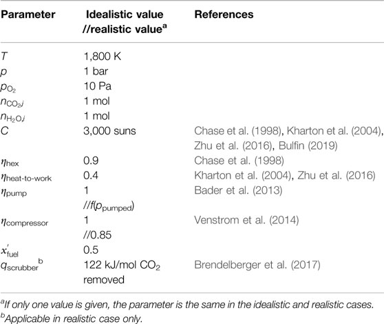
TABLE 2. Baseline parameters used in thermodynamic efficiency analysis.
Both thermodynamic modeling approaches yielded equivalent results, indicating that neglecting side reactions was justified. Details of the comparison of the two approaches are given in the Supplementary Material and Supplementary Table S3. Figure 4 compares the OMR, HMR, and DMR on the basis of (A) xfuel and (B) ηsolar-to-fuel under realistic assumptions, as functions of T. Note that if H2O is fed to the OMR, the net reaction is water splitting, not CO2 splitting. All chambers containing a chemical reaction are set to 1 bar total pressure. For the OMR and DMR,
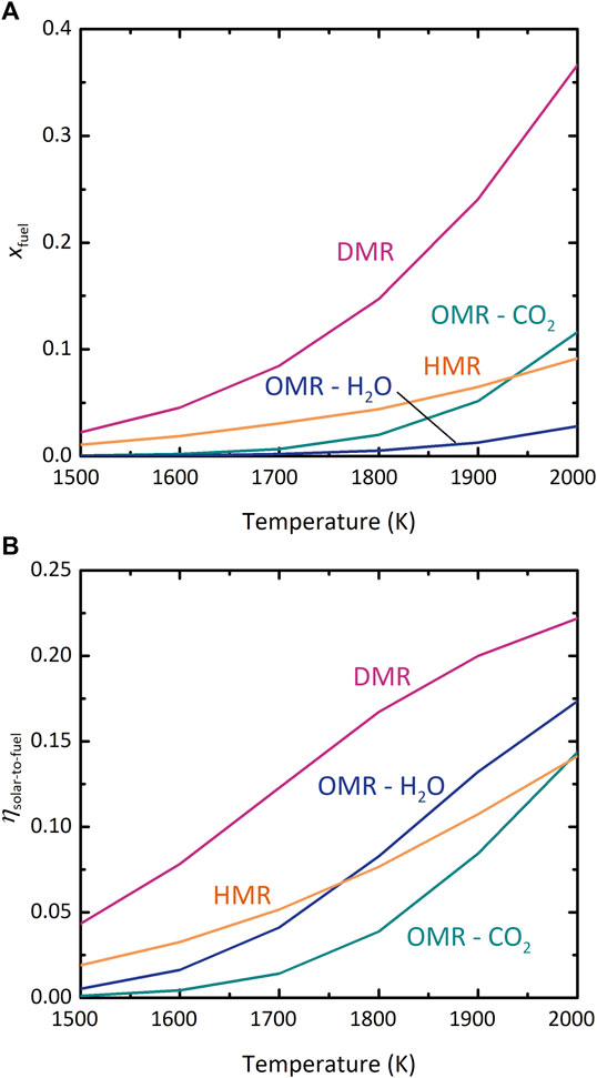
FIGURE 4. Comparison of the oxygen-membrane reactor (OMR), hydrogen-membrane reactor (HMR), and dual-membrane reactor (DMR) configurations. (A) xfuel vs. T, (B) ηsolar-to-fuel vs. T. pI, pII = 1 bar, where applicable.
In Figure 4A, xfuel in the DMR is higher than in the other configurations over the entire range of T. This result could be expected because the OMR and HMR each depend on a driving force across a single membrane, whereas the DMR benefits from the combined driving force of both membranes. Furthermore, effectiveness of each single membrane can be evaluated by comparing the “HMR” and “OMR–CO2” curves. At most T, driving the CO2-splitting reaction with
Figure 4B shows that the DMR also outperforms the OMR and HMR in terms of ηsolar-to-fuel. Furthermore, in the OMR the realistic efficiency of H2O splitting exceeds CO2 splitting, a reversal from the results for xfuel. Thermolysis of CO2 is thermodynamically more favorable than of H2O at these high temperatures, leading to higher xfuel, but the greater energetic cost of separating unreacted CO2 from the CO/CO2 mixture relative to condensing steam out of the H2/H2O mixture counteracts this benefit, resulting in lower ηsolar-to-fuel. This effect is also why a higher T is needed before the “OMR–CO2” efficiency curve overtakes that of the HMR relative to Figure 4A. As expected, the DMR exhibits advantages over the single-membrane OMR and HMR designs. The rest of this work examines the behavior of the DMR more closely; results of the individual analyses of the OMR and HMR are available in the Supplementary Material and Supplementary Figures S1–S5.
Figure 5 shows the detailed contributions to Qin at the maximum ηsolar-to-fuel for four scenarios. In case 1, pI and pII are equal at 1 bar. In case 2, pI is 10 bar and pII is 0.1 bar. The “X” applied to each case designates the alternative heat exchanger arrangement described in the efficiency analysis. Both case 1 and 1X include a large contribution for Qseparation, more than one-third of the total heat required, because xfuel is not high enough at these conditions. Case 2 and 2X do not incur any separation energy penalty, because xfuel is greater than the minimum specified in Table 2. Due to the higher conversion in case 2, Qreaction increases. The amount of O2 removed is also higher, leading to a significantly higher proportion of heat input going to
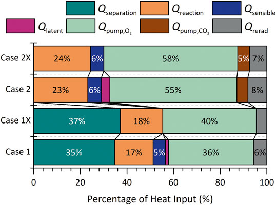
FIGURE 5. Distribution of the components of Qin for the dual-membrane reactor. Case 1: pI = pII = 1 bar. Case 2: pI = 10 bar, pII = 0.1 bar. The suffix “X” denotes the cross-stream arrangement of heat exchangers, whereas in the standard arrangement the inlet and outlet of the same stream exchange heat. T = 1,800 K and
Figure 6 shows the dependence in the DMR of xfuel and ηsolar-to-fuel on T at various
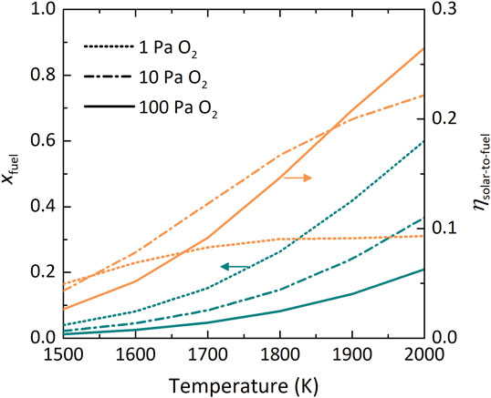
FIGURE 6. Dual-membrane reactor performance indicators xfuel (teal) and ηsolar-to-fuel (orange) as a function of T at various
Figure 7 shows the effect of the ratio of pressures in chambers I and II on the three performance indicators: (A) xfuel, (B) H2:CO molar ratio, and (C) ηsolar-to-fuel. T and
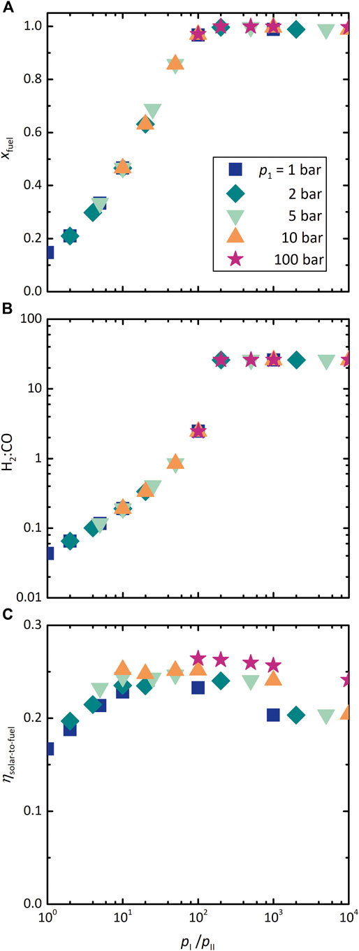
FIGURE 7. Effect of the dual-membrane reactor chamber pressure ratio, pI:pII, on (A) xfuel, (B) H2:CO molar ratio, and (C) ηsolar-to-fuel at various values of pI. T = 1,800 K and
Materials Outlook
Although the values of process parameters used here were chosen to be as realistic as possible, there are nevertheless many idealistic assumptions in this theoretical analysis. The most optimistic assumption is that materials for such high-temperature, selective membranes exist. To test the actual capabilities and limitations of the membrane reactor, functional membranes are first necessary. Kinetics, material stability, and membrane selectivity will affect the performance of a physical system. Oxygen-conducting membranes based on nonstoichiometric ceria have been characterized and demonstrated for solar-driven thermolysis of CO2 and H2O (Tou et al., 2017; Tou et al., 2019). The analog for hydrogen at these operating conditions has not emerged, but some insight may be gained from neighboring fields.
Hydrogen-conducting membrane materials have been studied in the context of sensors, hydrogen fuel cells, electrolyzers, and (de)hydrogenation reactions (Liu et al., 2006). Dense metallic membranes show high conductivity and selectivity of H+, but are limited to operation below 1,000 K. Furthermore, they are often Pd-based, which is expensive and impractical at the industrial scale (Tao et al., 2015). Considering the small size of H2, selective transport based on molecular sieving through micropores has also been suggested (Fletcher and Moen, 1977; Kogan, 1997; Tao et al., 2015). Here, controlling pore size and stability is a challenge, and perfect selectivity impossible (Kogan, 1998). Dense ceramics have also been shown to conduct H+, and are the only class of hydrogen-conductors stable at 1,800 K. Despite their own set of challenges, these mixed protonic-electronic conducting (MPEC) materials appear the most promising for hydrogen-conducting membranes.
Research has focused on perovskites, many of which are oxygen ion conductors. The compositions of perovskites that conduct hydrogen are limited, most often with Ba or Sr on the A site and Ce or Zr on the B site of the characteristic ABO3 structure (Iwahara et al., 1982; Fabbri et al., 2010; Dong et al., 2011). Several studies identified BaCe0.2Zr0.7Y0.1O3 (BCZY27) to be a promising composition (Dippon et al., 2016). Ba-based perovskites have the highest proton conductivities, but their electron conductivity tends to limit the overall transfer of hydrogen (Fabbri et al., 2010). For better electron conductivity, the B site is often doped with a trivalent dopant such as Y (Dong et al., 2011). Due to tradeoffs in protonic and electronic mobility, the optimal temperature range for proton conduction in MPECs is about 673–873 K (Bonanos and Poulsen, 1999; Fabbri et al., 2010). Even then, the flux of hydrogen through these materials is considered impractically low and requires membrane thicknesses on the μm-scale (Phair and Badwal, 2006; Dong et al., 2011). Furthermore, studies have found that Ba-based perovskites also conduct O2− at high temperatures, which is detrimental for our desired application in H2O thermolysis (Fabbri et al., 2010).
To check the behavior of an MPEC material at temperature conditions needed for membrane-assisted thermolysis, we prepared tubular BCZY27 membranes and tested them in a set of simple permeation experiments (experimental details in the Supplementary Material). Figures 8A,B show a photograph and a scanning electron microscopic image of representative membranes. As shown in Figure 8C, BCZY27 indeed conducts O2−, and in fact the measured flux of O2− is higher than H+ in the relevant range tested 1,073–1,773 K. Although the membrane thickness (∼800 μm) likely limited hydrogen diffusion, more importantly, these experiments revealed a critical lack of selectivity. In sum, the practicality of the DMR depends on the development of hydrogen-selective, high-temperature membranes, and more materials science research to this end is still necessary.
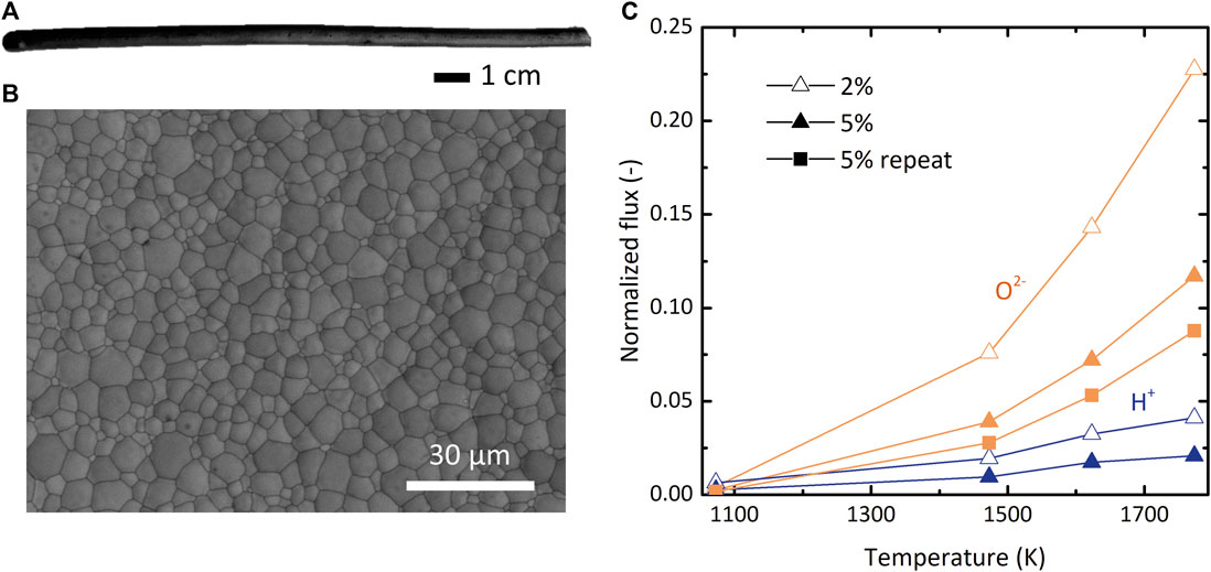
FIGURE 8. (A) Photograph of a representative BCZY27 membrane, which were tubular and closed on one end. (B) Scanning electron microscopic image of the inner surface of a BCZY27 membrane. (C) Normalized ionic flux of H+ (blue) and O2− (orange) at the respective H2 or O2 feed gas concentrations of 2% (hollow) and 5% (solid) through a BCZY27 membrane as a function of T. A repetition of 5% O2 feed with a different membrane is shown with square symbols.
Summary and Conclusions
We examined the concept of a thermochemical membrane reactor to split CO2 and produce solar fuels from a thermodynamic perspective for three configurations: a single oxygen-permeable membrane (OMR), a single hydrogen-permeable membrane (HMR), and an oxygen-permeable and hydrogen-permeable dual-membrane (DMR) configuration. The theoretical solar-to-fuel energy efficiency calculations for all configurations assumed thermodynamic equilibrium and made realistic process assumptions to highlight process limitations. Low product purity in the OMR at all realistic operating conditions leads to low ηsolar-to-fuel of CO2 thermolysis. The performance of the HMR depends on the choice of feed ratio, H2O:CO2, and values of xfuel and ηsolar-to-fuel are expected to be below 15%. As expected, the DMR outperformed the OMR and HMR. The thermodynamic model identified non-unique operating conditions where
Data Availability Statement
All datasets presented in this study are included in the article/supplementary material.
Author Contributions
MT wrote the manuscript, and developed the model together with her colleagues. She also performed the experimental work. AG did his master’s thesis with MT, working on the thermodynamic models discussed in the manuscript. ArS, performed experimental work on membranes and assisted with the modeling work. BB formulated the approach to the modeling together with MT, and assistant in writing the manuscript. AlS co-supervised the work and assisted in writing the manuscript. RM co-supervised the work and assisted in writing the manuscript.
Funding
This work was funded by the Swiss National Science Foundation (Ambizione Energy Grant No. 166883).
Conflict of Interest
The authors declare that the research was conducted in the absence of any commercial or financial relationships that could be construed as a potential conflict of interest.
Acknowledgments
We thank Noah Oswald and Severin Kull for helping develop the experimental procedure.
Supplementary Material
The Supplementary Material for this article can be found online at: https://www.frontiersin.org/articles/10.3389/fenrg.2020.570884/full#supplementary-material
References
Bader, R., Venstrom, L. J., Davidson, J. H., and Lipiński, W. (2013). Thermodynamic analysis of isothermal redox cycling of ceria for solar fuel production. Energy Fuels 27 (9), 5533–5544. doi: 10.1021/ef400132d.
Bonanos, N., and Poulsen, F. W. (1999). Considerations of defect equilibria in high temperature proton-conducting cerates. J. Mater. Chem. 9, 431–434. doi: 10.1039/a805150j.
Brendelberger, S., von Storch, H., Bulfin, B., and Sattler, C. (2017). Vacuum pumping options for application in solar thermochemical redox cycles – assessment of mechanical-, jet- and thermochemical pumping systems. Solar Energy 141, 91–102. doi: 10.1016/j.solener.2016.11.023.
Bulfin, B. (2019). Thermodynamic limits of countercurrent reactor systems, with examples in membrane reactors and the ceria redox cycle. Phys. Chem. Chem. Phys. 21, 2186–2195. doi: 10.1039/c8cp07077f.
Bulfin, B., Call, F., Lange, M., Lübben, O., Sattler, C., Pitz-Paal, R., et al. (2015). Thermodynamics of CeO2 thermochemical fuel production. Energy Fuels 29 (2), 1001–1009. doi: 10.1021/ef5019912.
Campbell, J. M. (2014). Gas conditioning and processing: the equipment modules. 9th Edn. Editors R. Hubbard and K. Snow-McGregor (Norman, OK: Campbell Petroleum Series), Vol. 2.
Chase, M. W., Davies, C. A., Downey, J. R., Frurip, D. J., McDonald, R. A., and Syverud, A. N. (1998). NIST-JANAF thermochemical tables: NIST standard reference database 13. Standard reference data program. National Institute of Standards and Technology.
Dippon, M., Babiniec, S. M., Ding, H., Ricote, S., and Sullivan, N. P. (2016). Exploring electronic conduction through BaCexZr0.9−xY0.1O3−d proton-conducting ceramics. Solid State Ion. 286, 117–121. doi: 10.1016/j.ssi.2016.01.029.
Dong, X., Jin, W., Xu, N., and Li, K. (2011). Dense ceramic catalytic membranes and membrane reactors for energy and environmental applications. Chem. Commun. 47 (39), 10886–10902. doi: 10.1039/c1cc13001c.
Ermanoski, I., Miller, J. E., and Allendorf, M. D. (2014). Efficiency maximization in solar-thermochemical fuel production: challenging the concept of isothermal water splitting. Phys. Chem. Chem. Phys. 16 (18), 8418–8427. doi: 10.1039/c4cp00978a.
Evdou, A., Nalbandian, L., and Zaspalis, V. (2008). Perovskite membrane reactor for continuous and isothermal redox hydrogen production from the dissociation of water. J. Membr. Sci. 325 (2), 704–711. doi: 10.1016/j.memsci.2008.08.042.
Fabbri, E., Pergolesi, D., and Traversa, E. (2010). Materials challenges toward proton-conducting oxide fuel cells: a critical review. Chem. Soc. Rev. 39 (11), 4355–4369. doi: 10.1039/b902343g.
Fletcher, E. A., and Moen, R. L. (1977). Hydrogen and oxygen from water. Science 197 (4308), 1050–1056. doi: 10.1126/science.197.4308.1050
Franca, R. V., Thursfield, A., and Metcalfe, I. S. (2012). La0.6Sr0.4Co0.2Fe0.8O3−δ microtubular membranes for hydrogen production from water splitting. J. Membr. Sci. 389, 173–181. doi: 10.1016/j.memsci.2011.10.027.
Garagounis, I., Kyriakou, V., Anagnostou, C., Bourganis, V., Papachristou, I., and Stoukides, M. (2011). Solid electrolytes: applications in heterogeneous catalysis and chemical cogeneration. Ind. Eng. Chem. Res. 50 (2), 431–472. doi: 10.1021/ie1001058.
Geffroy, P.-M., Fouletier, J., Richet, N., and Chartier, T. (2013). Rational selection of MIEC materials in energy production processes. Chem. Eng. Sci. 87, 408–433. doi: 10.1016/j.ces.2012.10.027.
Goodwin, D. G., Moffat, H. K., and Speth, R. L. (2009). Cantera: an object-oriented software toolkit for chemical kinetics, thermodynamics, and transport processes. Pasadena, CA: Caltech.
Iwahara, H., Uchida, H., and Maeda, N. (1982). High temperature fuel and steam electrolysis cells using proton conductive solid electrolytes. J. Power Sources 7, 293–301. doi: 10.1016/0378-7753(82)80018-9.
Kalogirou, S. A. (2004). Solar thermal collectors and applications. Prog. Energy Combust. Sci. 30 (3), 231–295. doi: 10.1016/j.pecs.2004.02.001.
Kharton, V., Marques, F., and Atkinson, A. (2004). Transport properties of solid oxide electrolyte ceramics: a brief review. Solid State Ion. 174 (1–4), 135–149. doi: 10.1016/j.ssi.2004.06.015.
Kogan, A. (1997). Direct solar thermal splitting of water and on site separation of the products – I. Theoretical evaluation of hydrogen yield. Int. J. Hydrogen Energy 22 (5), 481–486. doi: 10.1016/s0360-3199(96)00125-5.
Kogan, A. (1998). Direct solar thermal splitting of water and on-site separation of the products – II. Experimental feasibility study. Int. J. Hydrogen Energy 23 (2), 89–98. doi: 10.1016/s0360-3199(97)00038-4.
Leckel, D. (2009). Diesel production from Fischer-Tropsch: the past, the present, and new concepts. Energy Fuels 23, 2342–2358. doi: 10.1021/ef900064c.
Lewis, N. S. (2016). Research opportunities to advance solar energy utilization. Science 351 (6271), aad1920. doi: 10.1126/science.aad1920.
Li, S., Kreider, P. B., Wheeler, V. M., and Lipiński, W. (2019). Thermodynamic analyses of fuel production via solar-driven ceria-based nonstoichiometric redox cycling: a case study of the isothermal membrane reactor system. J. Sol. Energy Eng. 141 (2), 021012. doi: 10.1115/1.4042228.
Liu, Y., Tan, X., and Li, K. (2006). Mixed conducting ceramics for catalytic membrane processing. Catal. Rev. 48 (2), 145–198. doi: 10.1080/01614940600631348.
Marxer, D., Furler, P., Takacs, M., and Steinfeld, A. (2017). Solar thermochemical splitting of CO2 into separate streams of CO and O2 with high selectivity, stability, conversion, and efficiency. Energy Environ. Sci. 10 (5), 1142–1149. doi: 10.1039/c6ee03776c.
Muhich, C. L., Evanko, B. W., Weston, K. C., Lichty, P., Liang, X., Martinek, J., et al. (2013). Efficient generation of H2 by splitting water with an isothermal redox cycle. Science 341, 540–542. doi: 10.1126/science.1239454.
Noring, J. E., Diver, R. B., and Fletcher, E. A. (1981). Hydrogen and oxygen from water – V. The ROC system. Energy 6, 109–121. doi: 10.1016/0360-5442(81)90131-6.
Phair, J. W., and Badwal, S. P. S. (2006). Review of proton conductors for hydrogen separation. Ionics 12 (2), 103–115. doi: 10.1007/s11581-006-0016-4.
Rochelle, G., Chen, E., Freeman, S., Van Wagener, D., Xu, Q., and Voice, A. (2011). Aqueous piperazine as the new standard for CO2 capture technology. Chem. Eng. J. 171 (3), 725–733. doi: 10.1016/j.cej.2011.02.011.
Romero, M., and Steinfeld, A. (2012). Concentrating solar thermal power and thermochemical fuels. Energy Environ. Sci. 5 (11), 9234–9245. doi: 10.1039/c2ee21275g.
Schulz, H. (1999). Short history and present trends of Fischer–Tropsch synthesis. Appl. Catal. A Gen. 186 (1), 3–12. doi: 10.1016/s0926-860x(99)00160-x.
Steinfeld, A., and Palumbo, R. (2001). “Solar thermochemical process technology,” in Encyclopedia of physical science and technology (Cambridge, MA: Academic Press), 237–256.
Sunarso, J., Baumann, S., Serra, J. M., Meulenberg, W. A., Liu, S., Lin, Y. S., et al. (2008). Mixed ionic–electronic conducting (MIEC) ceramic-based membranes for oxygen separation. J. Membr. Sci. 320, 13–41. doi: 10.1016/j.memsci.2008.03.074.
Tan, X., and Li, K. (2007). Oxygen production using dense ceramic hollow fiber membrane modules with different operating modes. AIChE J. 53 (4), 838–845. doi: 10.1002/aic.11116.
Tao, Z., Yan, L., Qiao, J., Wang, B., Zhang, L., and Zhang, J. (2015). A review of advanced proton-conducting materials for hydrogen separation. Prog. Mater. Sci. 74, 1–50. doi: 10.1016/j.pmatsci.2015.04.002.
Tou, M., Jin, J., Hao, Y., Steinfeld, A., and Michalsky, R. (2019). Solar-driven co-thermolysis of CO2 and H2O and in-situ oxygen removal across a non-stoichiometric ceria membrane. React. Chem. Eng. 4, 1431–1438. doi: 10.1039/C8RE00218E.
Tou, M., Michalsky, R., and Steinfeld, A. (2017). Solar-driven thermochemical splitting of CO2 and in situ separation of CO and O2 across a ceria redox membrane reactor. Joule 1 (1), 146–154. doi: 10.1016/j.joule.2017.07.015.
Tuller, H. L. (2015). Solar to fuels conversion technologies. An MIT Future of Solar Energy Study Working Paper, Massachusetts Institute of Technology.
Venstrom, L. J., De Smith, R. M., Hao, Y., Haile, S. M., and Davidson, J. H. (2014). Efficient splitting of CO2 in an isothermal redox cycle based on ceria. Energy Fuels 28 (4), 2732–2742. doi: 10.1021/ef402492e.
Wang, H., Hao, Y., and Kong, H. (2015). Thermodynamic study on solar thermochemical fuel production with oxygen permeation membrane reactors. Int. J. Energy Res. 39 (13), 1790–1799. doi: 10.1002/er.3335.
Keywords: solar fuels, thermolysis, membrane reactor, solar syngas, reverse water gas shift
Citation: Tou M, Grylka A, Schuller A, Bulfin B, Steinfeld A and Michalsky R (2020) Dual Hydrogen- and Oxygen-Transport Membrane Reactor for Solar-Driven Syngas Production. Front. Energy Res. 8:570884. doi: 10.3389/fenrg.2020.570884
Received: 09 June 2020; Accepted: 17 August 2020;
Published: 02 September 2020.
Edited by:
Maurizio Troiano, University of Naples Federico II, ItalyReviewed by:
Qinghua He, Auburn University, United StatesLigang Wang, École Polytechnique Fédérale de Lausanne, Switzerland
Copyright © 2020 Tou, Grylka, Schuller, Bulfin, Steinfeld and Michalsky. This is an open-access article distributed under the terms of the Creative Commons Attribution License (CC BY). The use, distribution or reproduction in other forums is permitted, provided the original author(s) and the copyright owner(s) are credited and that the original publication in this journal is cited, in accordance with accepted academic practice. No use, distribution or reproduction is permitted which does not comply with these terms.
*Correspondence: Ronald Michalsky, ronald.michalsky@gmail.com