Abstract
Oxygen solubility is the rate-determining step (RDS) for the reduction reaction on the cathodes of molten carbonate fuel cells (MCFCs), especially at low operating temperatures below 600°C. The poor wetting property of the mixed ionic and electronic conductor (MIEC) coating, such as BYS (Bi1.5Y0.3Sm0.2O3-δ) on the NiO cathode, to the liquid electrolyte creates openings where oxygen absorption and dissociation take place to provide more oxide ionic species to electrochemical reaction sites (ERSs). Therefore, poor wetting MIEC-coated cells showed a much higher power density compared to standard cells, with a factor of 1.4 at the low operating temperature of 550°C. Long-term operation of 2500 hours with a low voltage loss of 9 mV suggests that BYS is a promising alternative cathode material for molten carbonate fuel cells.
Export citation and abstract BibTeX RIS

This is an open access article distributed under the terms of the Creative Commons Attribution Non-Commercial No Derivatives 4.0 License (CC BY-NC-ND, http://creativecommons.org/licenses/by-nc-nd/4.0/), which permits non-commercial reuse, distribution, and reproduction in any medium, provided the original work is not changed in any way and is properly cited. For permission for commercial reuse, please email: oa@electrochem.org.
Due to a significantly high ionic conducting property, molten carbonate is widely applied in many fields, with applications such as a high energy storage device molten air battery,1 electro-catalyst to enhance the oxygen reduction reaction (ORR) rate of low temperature hybrid MCFC/SOFC,2,3 and especially as an electrolyte for MCFCs.4 Lower operating temperature is one effective way to extend the lifetime of the MCFC stack because corrosion and electrolyte loss issues can be reduced significantly.5 However, low operating temperatures for MCFCs results in a high polarization of the cathode because of both slow gas diffusivity in electrolytes and sluggish reduction reaction rates.5–7 With the electrolyte diffusion problem, a common effective way to increase the oxygen solubility is to add additives to the molten salt mixture, such as lanthanum oxide material, or Rb2CO3 and Cs2CO3 into the mixture of Li/K carbonate.8,9 Nitrate or nitrite salts used as catalysts in molten carbonate are also used to increase the oxygen reduction reaction rates.10 However, abnormal corrosion on cell frames and current collectors with different types of electrolytes are disadvantageous from an economic point of view. Therefore, modification by coating a highly conductive material on the cathode surface is a simpler and more effective way to reduce cathode polarization. Many attempts have been made to accomplish this; for instance, coating the cathode with noble metal (silver)11 or mixed ionic electronic conductors (MIECs) (for example LSCF, LSC, GSC).12,13 However, it seems that the performance of the coated cells is not high or equivalent to standard cells, even though good MIEC materials were used as a coating, especially at low operating temperatures less than 600°C. These findings raise interesting questions for researchers in the molten carbonate field. We supposed that the low cathode performance of MIEC materials below 600°C is related to the wettability of the MIEC materials to the liquid electrolyte.
The effect of wetting on electrochemical performance has been studied under various conditions of different electrolyte compositions, temperatures and applied voltages.14 The electrochemical reaction occurring at triple phase boundaries (TPBs) refers to the current production at the wetted agglomerate surface. The surface tension of the solid/liquid (S/L) interaction is more important in determining the meniscus height of the molten salt on the material surface.15,16 Wetting is also an important phenomenon in material design for improving cell performance of the MCFC.14,17 Moreover, the TPBs can also be enlarged by using a low wetting material coated on the cathode, which creates a repelling effect on the molten salt to give more electrochemical reaction sites at a thinner electrolyte film.18
In this study, we used various materials, including metals and MIECs with different wetting ability to the liquid molten carbonate electrolyte, to determine the relationship between electrochemical cathode reactions and wettability changes. Bismuth oxide-based materials could be good candidates for this experiment. For example, bismuth oxide-based material is a popular electrolyte material for SOFCs because of its excellent oxygen-ion (O2−) conductivity.19 The delta phase of bismuth oxide (Bi2O3), a well-known phase of O2− conductivity, is easily stabilized at room temperature with the addition of Y or Eb to replace Bi sites.20,21 The low solubility of bismuth oxide in a molten medium over the course of the immersion time have been evaluated.22 However, bismuth oxide-based materials exhibit low wetting properties in ternary molten salts such as (Li/K/Na)2CO3.23,24 Recently, yttrium stabilized bismuth oxide or yttrium samarium stabilized bismuth oxide has been applied as both a membrane thickness controlling factor and an ionic conductor in high temperature carbon dioxide separation membranes, although the material stability in molten salt has not yet been proved. Therefore, stable bismuth oxide-based material with high mixed ionic and electronic properties and low wettability to the liquid electrolyte is the most suitable candidate for this experiment to understand the relationship between electrochemical cathode reactions and wettability changes.
Here, we systematically study coating materials on the cathodes of molten carbonate fuel cells in terms of durability and cell performance, and we investigate the reaction mechanism at low operating temperatures. Bismuth oxide-based materials coated on the cathode surface of molten carbonate give significantly high performance at the low operating temperature of 550°C. The ORR mechanism of coated cells was studied on symmetrical cells.
Experimental
Bismuth yttrium samarium oxide (BYS) and bismuth samarium oxide (BSO) are fabricated by the citrate method.25 The starting materials of Bi(NO3)3.5H2O, Y(NO3)3.5H2O, Sm(NO3)3.6H2O ( Sigma Aldrich, analysis type) were dissolved in diluted nitric acid solution ( 10 vol%) with the stoichiometric ratio. After stirring during heating, citric acid was added with a ratio of 2:1 as a chelating agent. The polymerization reaction was maintained at 100°C and stirred for at least 3 hours. The clear solution was continuously stirred on a hot plate at 80°C before being put it into the oven for drying overnight. The self-ignition process was conducted at 400°C before sintering green powder at 800°C for 3 hours. When the fabrication was finished, samples were characterized by X-ray diffraction (XRD, mini flex II, Rigaku). The sintered powder was ball- milled in 24 hours with ethanol as a solvent. Then, the dried powder was crushed by mortar and pestle. The uniform particle size (1–2 μm) was molded and pressed to make pellets under 2 tons. The pellets were sintered at 1100°C for 5 hours to ensure dense pellet formation. The wetting test was studied on an optical contact angle (OCA) system (Data Physics) with different temperature and gas compositions. The BYS coating solution was prepared by mixing BYS powder, 3 wt% BYK-190 (BYK-Chemie, Germany) as a dispersant in ethanol followed sonic scattering for 0.5 hour before coating the cathode. This solution was coated on a porous nickel plate (c.a. 80 % in porosity and 10 μm average pore size) by an infiltration method on different amounts of BYS powder from 1 to approximately 20 wt% before drying at 150°C for 20 min. The coating process was repeated until all BYS solution infiltrated the porous cathode. Finally, after drying overnight at 150°C, the BYS coated cathodes were ready for a single cell test.
Single cells using a modified cathode with an effective area of 100 cm2 were operated at 550°C. A Ni-based alloy anode, α-LiAlO2 matrices with a thickness of 1.5 mm, and (Li0.7/K0.3)2CO3 electrolyte sheets prepared by the tape casting method were used. A mixture of Air: CO2 = 70:30 was supplied as the cathode gas, and a mixture of H2:CO2:H2O = 72:18:10 was used as the anode gas. The H2O content in the anode gas was supplied using a humidifier at 50°C. The flow rate of the reaction gas was fixed to maintain the fuel and air utilization at 0.4. The open-circuit voltage (OCV), current density-voltage (I-V) characteristics, ohmic resistance and amount of nitrogen cross-over were measured to evaluate the performance of the single cell. The cell performances were evaluated by measuring the cell voltage at various current densities. A DC current was applied to the cell using an electric loader (ELTO DC Electronics Co., ESL300Z). To analyze the electrode polarization and ohmic resistance, an electro-chemical impedance analysis (EIS) was carried out in the open circuit voltage condition (OCV) using the Solatron S1287 and 1255B. The frequency range of the present EIS experiment was from 104 to 10−2 Hz.
Results
BYS coating on cathode morphology
The main phases of BYS powder were identified by X-ray diffraction characterization. Figure 1 shows the two main phases of bismuth samarium oxide and bismuth yttrium oxide. When compared with the X-ray diffraction pattern reference,25 the good fitting of the main peaks shows successful material fabrication. The microstructure of porous cathodes is an important factor that strongly affects the electrolyte distribution and the gas-phase diffusion in pore walls.26 Figure 2 shows the morphology of different coating amounts of BYS on the cathode. The coated cathodes exhibit uniformly dispersed BYS material with a particle size of 1–2 μm on macro and micro-pores of the cathode (Figure 2a, 2b). However, the covering effect of the coating powder to the porous cathode is shown on Figure 2c. In fact, porosity of the coated cathodes listed in Table I show that higher amounts of coating BYS material reduces the cathode porosity. After the lithiated process in a single test, the cathode porosity decreases due to volume expansion of the oxidation Ni base. The EIS spectra on Figure 3 show total polarization of 19.7 wt%, much higher than other coating samples. The significant increase in impedances in the low frequency range of 1 Hz to 0.01 Hz closely relates to gas-phase diffusion resistance.26,27 The increase in impedances means insufficient porosity for gas diffusion because small pore sizes result in high diffusion resistance. Therefore, in this study, the highest suitable coating amount is approximately 10 wt% of cathode weight.
Table I. Porosity of the modified cathode measured by ASTM 373–88.
| Sample | Porosity,% | ||
|---|---|---|---|
| Non-coated | 80 | ||
| 3 wt% BYS | 78 | ||
| 9.5 wt% BYS | 75 | ||
| 19.7 wt% BYS | 50 |

Figure 1. X-ray patterns of Samarium-doped Yttrium Bismuth oxide (BYS) sintered at 800°C for 3 hours.
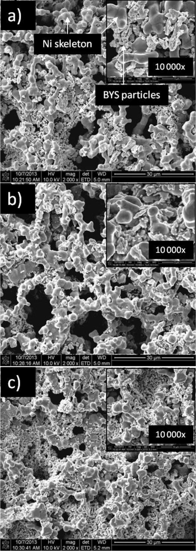
Figure 2. Morphologies of porous nickel cathodes with different a) 1.4 wt%; b) 9.5 wt%; c) 19.7 wt% BYS coating
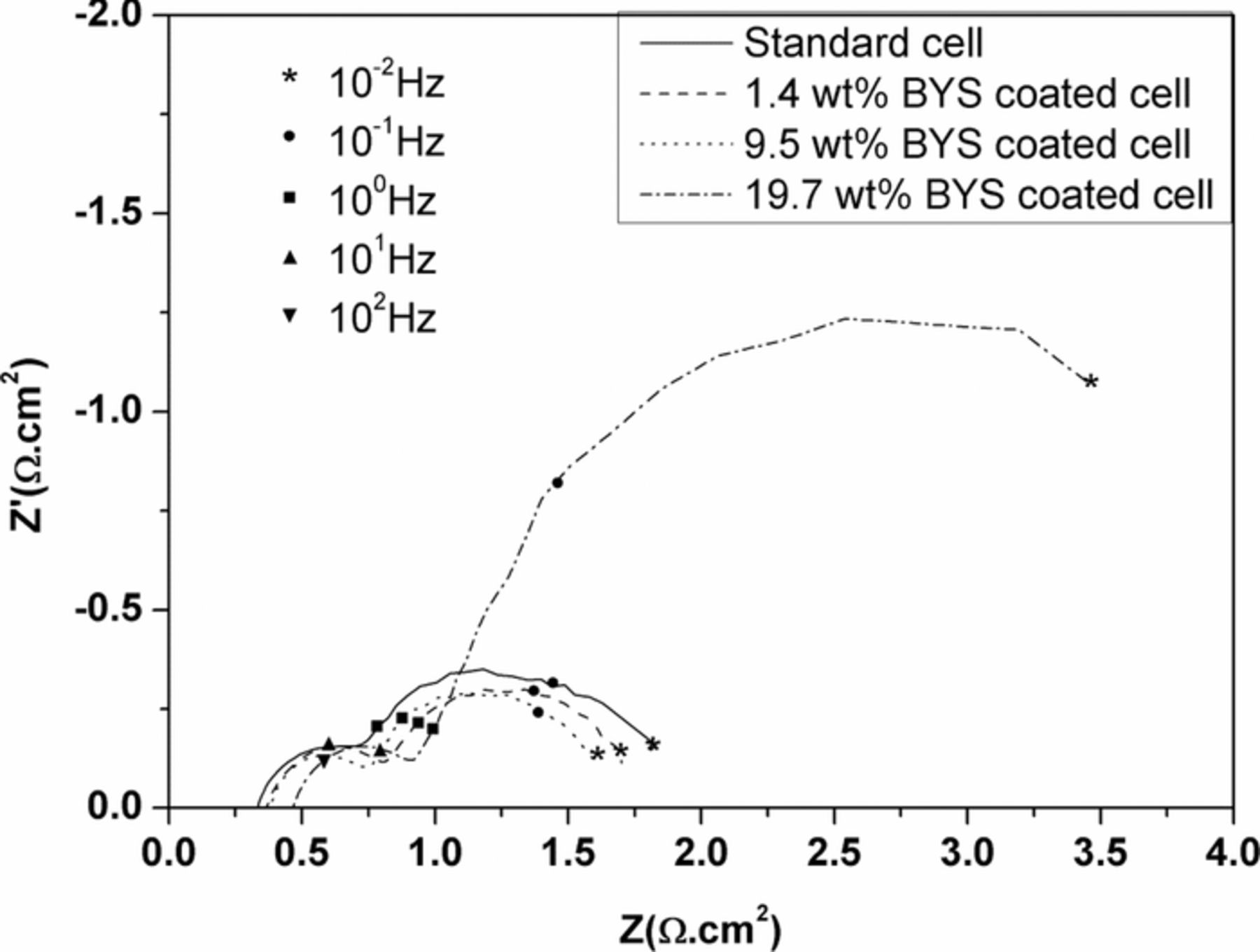
Figure 3. Impedance spectra of BYS-coated cells with various coating amount operated at 650°C after 200 hours.
Effect of BYS coating on cell performance
The power densities of the modified cells in Figure 4 appear higher compared to the power density of the standard cells in three different temperature ranges. The amounts of BYS powder loaded on the cathode are proportional to the obtained power densities in Figure 4a. With a BYS loading amount of 9.5 wt%, the highest power densities are 182, 160, 130 mW.cm−2 at 650°C, 600°C and 550°C, respectively. It is interesting that the power density of a standard cell at 550°C is only 90 mW.cm−2 lower than the power density of a 9.5 wt% BYS coated cell. The cell performance of 9.5 wt% Bi2O3 and 9.8 wt% BSO coated cells at different temperatures in Figure 4b show higher power densities than the standard cell even at a very low temperature of 500°C. The cell performance of Bi2O3 is lower than the BSO coated cell and BYS coated cell. The detail interpretation is mentioned in a later section.

Figure 4. a) Power densities of BYS-coated cells at different operating temperature of 550°C, 600°C and 650°C after 300 hours. b) Power densities of Bi2O3-, BSO- and BYS-coated cells at different operating temperature of 500°C, 550°C and 600°C after 300 hours.
Comparison of electrode resistances at low temperatures and long-term operation of the coated cells
Generally, the EIS curve usually shows two semi-circles: the first, at high frequencies relates to charge-transfer resistance (R2) and the second, at low frequencies relates to mass-transfer resistance (R3), such as gas diffusion in a porous structure and gas solubility into molten salt and gas diffusion through electrolyte film.28 Because the cathode microstructure of both cases is similar in porosity and pore size, similar gas-phase diffusion resistance should certainly be obtained. We replaced the different diffusing species of N2 with He on cathode gas of the standard full cell in order to identify the gas-phase diffusion reactions; Figure 5 shows the overlap of two impedance spectra and only separates at low frequency of 1 Hz. The different magnitude of two impedances, however, is very small, which means that gas phase diffusion has almost no effect on diffusion resistance. This result is in good agreement with Yuh and Selman's conclusion when they studied the effect of gas-phase diffusion.29,30 Therefore, the effect of gas diffusion through a porous cathode is possibly negligible when using the modified cathode with coatings below 9.5 wt% BYS. The electrode resistance at high frequency (R2) and electrode resistance at low frequency (R3) are shown in Figure 6, which were calculated by equivalent circuit of nonlinear least square fitting methods. The ohmic resistance (Ro) of standard cell shown in Figure 6a increased with lower temperatures and obtained similar value on both cells. The calculated value from the equivalent circuit shows a total polarization of BYS-coated cells smaller than the standard cell. Figure 6b shows the low frequency resistance (R3) is the rate-determining step at a temperature of 650°C and shifts to mixed control of R2 and R3 at a lower temperature of 600°C on both cells. However, it is interesting that R3 is more dominant from 550°C to 500°C on the standard cell, while on a BYS-coated cell, mixed control is still dominant at 550°C and slowly converts to mass-transfer control (R3) from 520°C to 500°C. Figure 6c shows the magnitudes of R2 of all cell loops are smaller than standard cells in the temperature range of 500°C to 650°C; the reduction reaction rate on the BYS-coated cell most likely was faster than the standard one and the main difference was a much smaller magnitude of R3 at the BYS-coated cell, especially at temperatures below 600°C.
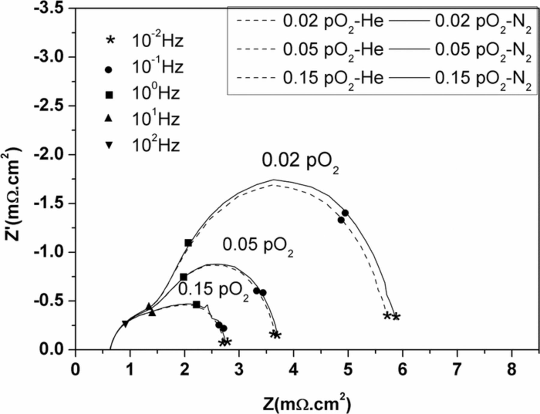
Figure 5. Effect of gas-phase diffusion on impedance of standard cell at 650°C.
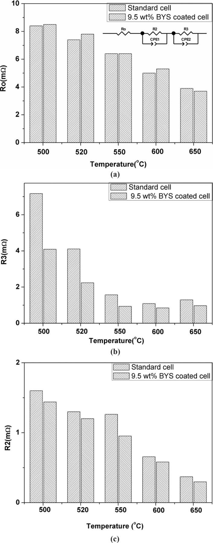
Figure 6. a) Comparison of ohmic-resistance (Ro) of standard cell and coated cell at various opereating temperatures. b)Comparison of mass-transfer resistance (R3) of standard cell and coated cell at various opereating temperatures. c) Comparison of charge-transfer resistance (R2) of standard cell and coated cell at various opereating temperatures.
Long-term operation of the BYS-coated cell shows stable performance during more than 2500 hours at a low operating temperature of 620°C in Figure 7. The cell voltage of the 9.5 wt% BYS-coated cell was stable and above 0.8 V at a current density of 150 mA.cm−2, with a voltage loss of 9 mV per 1000 hours of confirmed material stability in a molten salt environment.
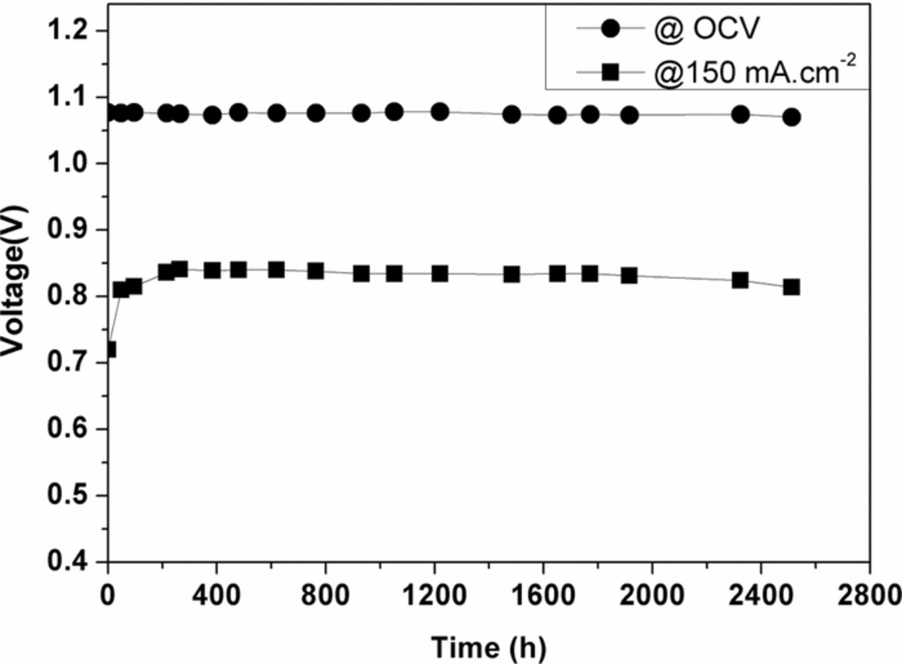
Figure 7. Long-term operation of BYS-coated cell at 620°C under current loading of 150 mA.cm−2.
Discussion
Mass-transfer resistance in molten carbonate fuel cell (R3, < 100Hz)
The separation of the He-curve and the N2-curve, at a low frequency of 1 Hz on impedance spectra of symmetrical cells, shown in Figure 8a, reconfirms that there is no effect of gas-phase diffusion in a porous cathode. In addition, at low operating temperatures of below 600°C, a new semi-circle (R1) occurred at very high frequencies above 102 Hz to 103 Hz, which was suggested to slow O2 diffusion and chemical reaction of dissolved oxygen species with molten carbonate in literatures.31,32 However, its physical meaning is still controversial and the resistance seems very small compared to total polarization, so in this study we do not consider it as main kinetic or diffusion impedance. The total electrode polarization of the BSO-coated cell in Figure 8b shows significantly smaller than the standard cell especially at low operating temperatures below 550°C. The R3 of the standard cell in Figure 9a shows much higher than the R3 of the BSO-coated cell in Figure 10a especially at the temperatures of below 600°C suggests higher O2 solubility to molten salt or additional O2 transport in other pathways to electrolyte film. Figure 9 and Figure 10 show gas dependencies of standard and BSO-coated cells in log-log plots. The pO2 dependencies of R3 of the standard cell range from -1 to -0.85 (Figure 9a) and CO2 dependencies of R3 range from 0.09 to -0.27 (Figure 9b) at low temperature ranges from 500°C to 550°C. The pO2 dependencies of ∼ -1.0 suggest physical solubility of oxygen molecules in molten salt, which are in good agreement with literature.33,34 Small pCO2 dependencies of R3 can be explained by low oxygen solubility because the electrochemical reactions involve both CO2 and O2, simultaneously. Therefore, both O2 and CO2 gases follow the rate-determining step of physical solubility in molten carbonate at low operating temperatures below 600°C. At higher temperatures above 600°C, highly soluble CO2 molecules to molten salt is observed with higher pCO2 dependencies, while pO2 dependencies of R3 are approximately -0.64; thus, O2 possibly follows a chemical dissolution pathway.33,35 The higher pCO2 dependencies is because a high O2 solubility results in a large amount of O2 molecules in the liquid electrolyte, enough to react with CO2 at over 600°C. Thus, we can see the strong pCO2 dependencies in these high temperature ranges.

Figure 8. Impedance of symmetrical a) standard cell; b) BSO-coated cell operated under 50 % pCO2 and 2 % pO2 with balancing gases of N2 and He at different operating temperatures.

Figure 9. a) Oxygen dependency to impedance at different temperature of standard symmetrical cell. b) Carbon dioxide dependency to impedance at different temperature of standard symmetrical cell.

Figure 10. a) Oxygen dependency to impedance at different temperature of BSO coated symmetrical cell. b) Carbon dioxide dependency to impedance at different temperature of BSO coated symmetrical cell.
However, the pO2 dependencies of R3 on the BSO-coated cells show values near -0.5, suggesting different O2 solubility mechanisms shown in Figure 10a. It is impossible to dissolve oxygen molecules into molten carbonate to create oxide ions except for peroxide, superoxide or perhaps peroxocarbonate ions.35 The coated cells showed similar behavior of pCO2 dependencies of R3 in Figure 10b. Therefore, the different pO2 dependencies of R3 between the standard cells and the BSO-coated cells suggest different electrochemical reactions regarding oxygen reduction reactions.
Charge-transfer resistance in molten carbonate fuel cells (R2, 102H z ∼101Hz)
The pO2 dependencies of R2 on the standard cell are approximately in the range of -0.1 and -0.32 at the whole temperatures (500°C ∼ 650°C) in Figure 9a. The pO2 dependencies of R2 on the BSO-coated cell are from -0.21 to -0.34 (Figure 10a) at the same temperatures. Both the standard cell and the BSO-coated cell show little or no pCO2 dependencies of R2 in the whole temperature ranges from 500°C to 650°C as shown in Figure 9b and Figure 10b. Compared to the reaction orders listed in Table II, the pO2 dependencies of R2 (∼ -0.3) above 600°C are close to the theoretical value of 0.375 (peroxide mechanism, peroxycarbonate mechanism, and oxygen mechanism II) and no pO2 dependencies of R2 data matching the theoretical values are observed at low temperatures below 550°C. These results may be the result of the lack of oxygen molecules at the electrochemical reaction sites due to mass-transport resistance predominance.
Table II. Reaction mechanism pathways at the cathodes of molten carbonate fuel cells.29–31
| Reaction mechanism | Reaction steps | Exchange current density |
|---|---|---|
| The peroxide mechanism | 1. O2 + 2CO32 −↔2O22 − + 2CO2 | i = iop0.375O2p− 1.25CO2 |
| 2. O22 −+e−↔O2 −+O−(RDS) | ||
| 3.O− + e−↔O2 − | ||
| 4. O2 − + CO2↔CO32 − | ||
| The superoxide mechanism | 1.2CO32 − + O2↔2O22 − + 2CO2 | i = iop0.625O2p− 0.75CO2 |
| 2.O2 + O22 −↔2O2− | ||
| 3.O2− + e−↔O22 −(RDS) | ||
| 4. O22 − + e−↔O2 − + O− | ||
| 5. O− + e−↔O2 − | ||
| 6. O2 − + CO2↔CO32 − | ||
| The peroxycarbonate mechanism | 1. 2CO32 − + O2↔2CO42 − | i = iop0.375O2p− 0.25CO2 |
| 2. CO42 − + e−↔CO32 − + O−(RDS) | ||
| 3. O− + e−↔O2 − | ||
| 4. O2 − + CO2↔CO32 − | ||
| The oxygen mechanism I | 1. O2(g)↔O2(e) | i = iop0.875O2p− 0.25CO2 |
| 2. O2(e) + e − ↔O2−(RDS) | ||
| 3. O2− + e−↔O22 − | ||
| 4. O22 − + e−↔O2 − + O− | ||
| 5. O− + e−↔O2 − | ||
| 6. O2 − + CO2↔CO32 − | ||
| The oxygen mechanism II | 1. O2(g)↔O2(e)− | i = iop0.375O2p− 0.25CO2 |
| 2. O2(e)↔2O (at the electrode − electrolyte interface) | ||
| 3. O + e−↔O−(RDS) | ||
| 4. O− + e−↔O2 − | ||
| 5. O2 − + CO2↔CO32 |
In this study, we cannot say what electrochemical reaction mechanism of the R2 is. But it is clear that the coated cells have similar electrochemical reactions of R2 with the standard cells and the BSO- and BYS-coatings mainly change the R3 which is strongly related to O2 solubility to molten salt or additional O2 transport in other pathways to electrolyte film.
Effect of wetting behavior on cell performance
Gas molecule diffusion through a liquid electrolyte to the electrochemical reaction sites can be improved if the electrolyte film thickness is reduced.36 The wetting properties of a material are listed in Table III. All BSO, pure Bi2O3 and BYS materials are poor wetting materials to the liquid molten carbonate, whose contact angles are above 40° compared to nickel oxide, SDC and LSCF materials, whose contact angles are less than 10°. The effect of meniscus height under OCV condition is considered by electrocapillary effect only and is not significantly affected by gas composition.15–17 Thus, when poor wetting materials were coated on the cathode, the electrolyte thickness film was changed, resulting in a reduction in diffusion resistance. To understand the effect of wetting behavior on cell performance, a lead (II) oxide coated cell is conducted. Because PbO is a non-conducting material and has poor wetting with the liquid molten salt, we can only see the wetting effects on cell performance. Figure 11a shows low performance of the PbO-coated cell compared to the standard cell performance. A very high total polarization of the PbO-coated cell with a factor of 3 compared to that of the standard cell and both large charge-transfer resistance (R2) and mass-transfer resistance (R3) are main factor especially at the low operating temperature of below 550°C (Figure 11b). It is explained by the highly soluble PbO in the carbonate and covering effect of a coating material to active electrochemical reaction sites due to a change of electrolyte properties in molten salt.22 However, the single cell performance of a pure Bi2O3-coated cell shows much higher cell performance than the others. Figure 4a, Figure 4b, and Figure 11a show that the poor wettability of coating materials to an electrolyte with an MIEC property (Bi2O3, BSO, BYS) is a possibly dominant factor in comparison with good wettability, regardless of their MIEC property (LSCF-coated cell and SDC-coated cell) or the poor wettability of a coating material without an MIEC property (PbO).
Table III. Wetting behavior of material in the cathode condition at 600°C.
| Model | Sample | Contact angle, degree |
|---|---|---|
| Model I | Good wetting, Lithiated NiO | 2.5(measured) |
| Model II | Good wetting, O2− conductor ( SDC) | 8(measured) |
| Model III | Good wetting, mixed ionic electronic conductor (LSCF) | <10(measured) |
| Model IV | Poor wetting, non-conducted material ( PbO) | 61(measured) |
| Model V | Poor wetting, noble metal, non-wetted (Pt, Au) | 30(measured) |
| Model VI | Poor wetting, MIEC ( BYS, BSO, BYO and Bi2O3) | ∼45–50(measured) |

Figure 11. a) Power densities of the cells coated with various materials after operating time of 300 hours at operating temperature of 550°C. b)Impedance spectra of symmetrical PbO-coated cell cell operated under 50 % pCO2 and 2 % pO2 with balancing gas of N2 at different operating temperatures.
Analysis of the reaction mechanism
Table IV shows similar R2 activation energy regardless of the coating and different experimental conditions. Generally, the R2 activation energy is in the range of [80-100] kJ/mol and suggests a similar reaction mechanism of the two cases.13,31,37 In the low pO2 condition (2 %), the R3 activation energy on the coated cell showed much lower values than that of the standard cell, which strongly confirms a different mechanism of oxygen reduction reactions. For the standard cell, the significantly large pO2 dependency values of R3 (∼ -1.0) at low temperature ranges (<600°C) are supposed to be related to the rate-determining step (RDS) of O2 solubility with an activation energy of 137.9 kJ/mol. Table V33,38,39 shows the calculated activation energy of reactant gas solubility and diffusivity in various electrolyte compositions below 600°C. The diffusion activation energy of O2 and CO2 through a liquid electrolyte is almost 20 kJ/mol. The activation energy of O2 solubility (160 kJ/mol in 62 mol% Li2CO3/38 mol% K2CO3), however, is much higher than that of CO2 solubility (19.8 kJ/mol in 43 mol% Li2CO3/ 32 mol% Na2CO3/ 25 mol% K2CO3). Thus, this activation energy value of the R3 (137.9 kJ/mol) of the standard cell is close to the activation energy of O2 solubility. However, the similarity of the R3 activation energy of the coated cells to O2− conductivity activation energy of 80 kJ/mol of the BYS material25 and pO2 dependencies of R3 (∼ -0.5) at low operating temperatures below 550°C suggest another pathway to transport O2− through the MIEC coating materials. In the low pCO2 condition (1%), R3' activation energy is similar with the CO2 solubility and diffusivity activation energy on the standard cell (Table V). This suggests that R3' in the low pCO2 stands for CO2 solubility or CO2 diffusivity through the electrolyte. The effect of CO2 solubility with small activation energy (∼20 kJ/mol) is not very important at normal pCO2 conditions of over 30 % and low operating temperatures below 550°C because the effect of O2 solubility with large activation energy (∼160 kJ/mol) is more predominant at these low operating temperatures.
Table IV. Activation energy of coated symmetrical cells at different gas partial pressure conditions (kJ/mol).
| 2 % pO2 | 70 % pO2 | 1 % pCO2 | 50 % pCO2 | |||||
|---|---|---|---|---|---|---|---|---|
| Sample | R2 | R3 | R2 | R3 | R2 | R3 | R2 | R3 |
| Standard cell | 79.1 | 137.9 | 106.0 | 120.3 | 97.1 | 36.8 | 103.8 | 175.1 |
| BSO coated cell | 76.0 | 90.7 | 94.4 | 110.7 | 99.6 | 21.6 | 93.5 | 119.4 |
| BYS coated cell | 69.6 | 77.3 | 90.8 | 117.3 | 94.8 | 26.6 | 89.7 | 117.2 |
Table V. Calculated activation energy of gas solubility and gas diffusivity in different molten salts in low temperature range of [500°C-550°C].33,38,39
| Diffusivity | Solubility | |||
|---|---|---|---|---|
| O2 | CO2 | O2 | CO2 | |
| (Li/K)2CO3 (50:50) | – | – | 170.3 | – |
| (Li/K)2CO3 (62:38) | 16.4 | 20.3 | 160 | – |
| Li/Na/K)2CO3 (43:32:25) | – | – | – | 19.8 |
Figure 12a describes the reaction pathways in the case of the cathode coated with good wetting materials. At operating temperatures, model I shows the oxygen molecule solutes and diffuse through electrolyte film to the active surface in step 1, then the absorbed oxygen dissociated on the surface of oxygen atoms before reacting with carbonate ions to create oxide ions (O2−, O22−, O−, O2−, etc) in step 2. After that, the electronic exchange reaction of oxide ions, such as peroxide or superoxide, with the lithiated NiO surface in step 3 occurs before the recombination reaction of the oxide ion and dissolved CO2 to create carbonate ions in the electrolyte or on the lithiated NiO surface. Especially at low operating temperature below 550°C, slow O2 dissolution kinetics is dominant at the cathode working condition, resulting in low cell performance of the standard cell. Therefore, at low operating temperatures where liquid electrolytes have very low oxygen solubility, whenever any good wetting material coated on the cathode surface with a high O2− conductor or mixed ionic electronic conductor as in model II or model III, they will become inactive areas under a molten salt film and cause the covering effect to the lithiated NiO surface, finally resulting in the high charge-transfer resistance or increased internal resistance and also high mass-transfer resistance of O2 solubility in the liquid electrolyte.
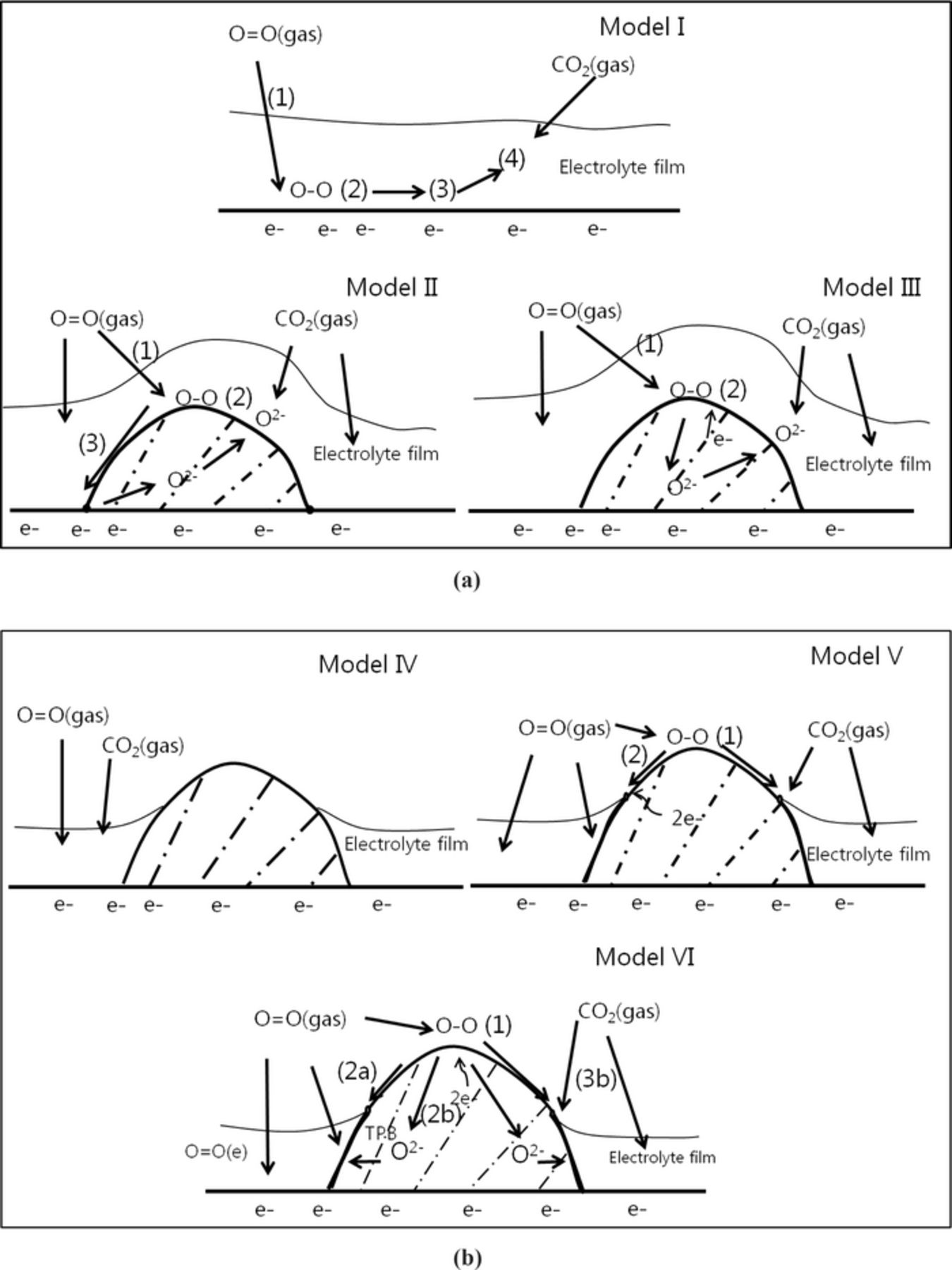
Figure 12. a)Models for reaction pathway of good wetting material coated on cathode in molten salt medium. b) Models for reaction pathway of poor wetting material coated on cathode in molten salt medium.
Model IV of Figure 12b shows the schematic diagram of a cell coated with poor wetting material which has no O2− and electron conductivities (PbO coated cell). At low temperatures 550°C, where O2 solubility is the RDS, the diffusion pathway of O2 is limited by electrolyte film thickness because no electrochemical reaction sites are on the open area. Due to non-conducting properties, however, cell performance is possibly not improved or even worse because of the covering effect to active sites on the lithiated NiO surface. In model V, for a cell coated with a poor wetting metal (non-oxygen-ion conductor, Au, Ru), the absorbed oxygen molecule is dissociated on the surface before having an electrochemical reaction nearby with triple phase points. Because of the low solubility and slow diffusivity of O2 into molten salt, there are few oxide ions on meniscus areas. Therefore, the recombination reaction of CO2 and oxide ions only occurs at the metal/gas/electrolyte triple phase boundary, and it cannot greatly improve cell performance.
However, model VI shows poor-wetted and O2− and electronic mixed conductors coated on the lithiated NiO surface. The open areas due to poor wetting to molten salt help oxygen absorption and dissociation (step 1), is confirmed by the O2 reaction order (∼0.5) of diffusion on coated cells in Figure 10a. Then, these oxygen atoms will exchange electrons to create O2−, which are diffused on the BYS surface and bulk (step 2a and 2b). Although the sintered Bi2O3 at high temperature is a p-type conductor (at 500–650°C), the existence of delta phases of Bi2O3 shows that its electronic conductivity is more dominant than ionic conductivity.40 However, BSO has better ionic conductivity than Bi2O3 because Bi sites are replaced with Sm dopants to stabilize delta phase while maintaining the electronic conductivity.41 The co-doped yttrium and samarium to Bi2O3 can enhance the O2− conductivity in addition its electronic conduction.25 Therefore, fast O2− species transport in bulk and surface to reaction areas provide lots of oxygen species at the meniscus area where it is believed to have electrochemically active areas.15,16 Thinner electrolyte films can result in easier CO2 diffusion to new active surfaces for the recombination reaction of CO2 and oxide ions in step 3b. Therefore, we have low polarization in both kinetic and diffusion resistance. Figure 13 shows impedance spectra of different coating materials on cathode cells at an operating temperature of 620°C. Noble metal (Au and Ru) coated cells show very large impedances because of a lack of reaction sites and O2− transport ability on bulk, while a good wetting material coated cell shows very similar impedance to the standard cell because coating areas are deactivated below the electrolyte film.

Figure 13. Impedance spectra of the cells coated with various materials at operating temperature of 620°C after operation of 200 hours.
Although the wetting of electrolyte depends on surface tension, transport gradient of ions to meniscus height and current loading, similar electrolyte properties and small electrode polarization because of ion transport proves that wetting properties do not undergo any significant change under loading and non-loading conditions. The reaction orders of the electrochemical reaction on the coated cells are close to 0.375, suggesting that the reaction follows the peroxide mechanism pathways in high temperature ranges of [600°C-650°C]. For the standard cells, only narrow temperature ranges show a similar mechanism. Below 600°C, it is difficult to draw conclusions about the reaction mechanism because of slow O2 solubility into molten salt. However, the exact reaction mechanism at the cathode is still doubtful because several conclusions have been claimed about the reaction mechanism at the cathode, such as the peroxocarbonate mechanism2,31 or mixed of superoxide and peroxide mechanism.9
Conclusions
Bismuth oxide-based material, MIECs, coated cells showed a significant performance increase at low operating temperatures below 600°C. This is because the poor wetting properties of bismuth oxide-based material to molten salt creates another pathway to transport O2− under the electrolyte film, providing more reaction sites, while the O2 reaction sources are limited by low O2 solubility at low operating temperatures 600°C at the standard cathodes. The reaction possibly followed one mechanism on the coated cells at the temperature ranges from 500°C to 650°C and was similar to the standard cell above 600°C. It is also difficult to understand the reaction mechanism of the standard cell at temperatures below 600°C because of mass-transport limitation by slow O2 solubility. The stability of cell performance during long-term operation of more than 2500 hours suggested the phase stability of bismuth oxide-based materials. As a result, bismuth oxide-based material such as BYS, a low wetting mixed ionic electronic conductor, is a promising alternative material for cathode surface modification to reduce the cathode polarization, especially at low operating temperatures below 600°C in molten carbonate fuel cells.
Acknowledgments
This work was supported by the In-house Program (2E24842) of the Korea Institute of Science & Technology (KIST), Republic of Korea and the Renewable Energy R&D Program of the Korea Institute of Energy Technology Evaluation and Planning (KETEP) grant funded by the Ministry of Knowledge Economy, Republic of Korea (No. 20113030030040).