Abstract
We present the first alkaline redox flow battery (a-RFB) based on the coordination chemistry of cobalt with 1-[Bis(2-hydroxyethyl)amino]-2-propanol (mTEA) and iron with triethanolamine (TEA) in 5 M NaOH. The overall redox system has a cell voltage of 0.93 V in the charged state. Importantly, the coordination compounds are negatively charged and have limited transport through the cation exchange membrane (e.g., Nafion), minimizing the extent of redox species crossover during charge-discharge cycling. Fe-TEA is electrochemically reversible and soluble up to 0.8 M, whereas Co-mTEA presents quasireversible electron transfer kinetics and can be solubilized up to 0.7 M. Cyclability was tested with a flow cell at a concentration 0.5 M up to 30 cycles using a 50 μm thick Nafion membrane, at 30 mA/cm2, with minimal crossover (less than 4% of net concentration) or evolution of gases detected.
Export citation and abstract BibTeX RIS

This is an open access article distributed under the terms of the Creative Commons Attribution 4.0 License (CC BY, http://creativecommons.org/licenses/by/4.0/), which permits unrestricted reuse of the work in any medium, provided the original work is properly cited.
The redox flow battery (RFB) has excellent potential for electrical grid energy storage. However, it has not yet been widely deployed often because of problems of stability and limited cycle life. In this report we describe the use of coordination compounds of cobalt with 1-[Bis(2-hydroxyethyl)amino]-2-propanol (mTEA, Figure 1A), and iron with triethanolamine (TEA, Figure 1B) in 5 M NaOH as a RFB. The flow battery was optimized to achieve stable cycling with 71% average energy efficiency in 30 cycles when passing 30 mA cm−2, and using a 50 μm–thick Nafion membrane as the separator, at a concentration 0.5 M. Importantly, crossover of the redox species through the membrane was below 5% of the original concentration at the end of the 30th cycle, with no evolution of gases detected during cycling.
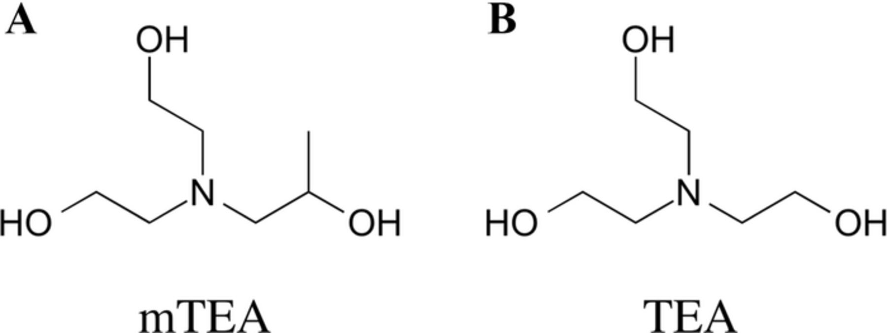
Figure 1. Ligands used in this work: 1-[Bis(2-hydroxyethyl)amino]-2-propanol (mTEA), and triethanolamine (TEA).
We developed this alkaline RFB as an alternative to state of the art RFBs, e.g., the all vanadium RFB, which are based on acidic electrolytes.1 Acidic RFBs often suffer capacity fading due to membrane crossover and the occurrence of undesired secondary reactions during battery cycling (e.g., precipitation, evolution of H2 and Cl2 gases).2 Acidic electrolytes have a high conductance, Gmax = 825 mS cm−1 for 3 M H2SO4(aq),3 but tend to be corrosive to the cell components, which translates into high operational and maintenance costs.4 In contrast, alkaline electrolytes such as NaOH have lower conductance, Gmax = 410 mS cm−1 for 3.7 M NaOH(aq)3, but are less corrosive. Alkaline electrolytes employing transition metals generally require the use of coordination compounds as redox species to prevent precipitation of the hydroxides or hydrous oxides. The net charge on these ions can be tailored by ligand selection to minimize membrane crossover with a cation exchange membrane. Moreover, different ligands can be used to tune the electrode potential of the half-cells to optimize the voltage of the battery.5
The formation of chemically stable soluble coordination compounds of cobalt and iron in 5 M NaOH is challenging because of a thermodynamic tendency to form their insoluble hydroxides. For iron(III), with a solubility product, Ksp, of the corresponding hydroxide, a strong interaction must exist between the Fe(III) ion and an organic ligand, L, so that the stability constant of the complex formed, β, is considerably larger than the Ksp of the metal hydroxide, i.e. β[L] ≫ Ksp, [OH]3. Thus log βFe(III) must be larger than about 39 for [OH-] = 5 M, [L] = 1 M, and [Fe(L)] = 1 M. We carried out experiments to find coordination compounds that were chemically stable in 5 M NaOH (with log β ≈ 39), redox active with a very negative E0' but in the potential window of the electrolyte, and that had fast heterogeneous electron transfer kinetics. This was achieved by coordination of Fe with TEA and of Co with mTEA. In previous reports, complexes of these two metal ions with amino-alcohol ligands such as TEA were successfully synthesized in base and used in analytical determinations,6–8 electrodeposition,9,10 electrochemical studies,11,12 and the reduction of dyes.13–15 The Yang group has previously proposed the use of Fe-TEA as the negative redox couple in RFB studies with the Br2/Br− as the positive one.16 However, Br2 is not stable when it contacts strong base and it is not possible to maintain and operate a RFB with different pHs on different sides of the ion exchange membrane. Thus their battery showed poor coulombic performance. This problem was addressed in the present work by finding a chemically stable positive redox couple in 5 M NaOH, Co(II/III)-mTEA. This couple is negatively charged and electrochemically quasireversible in 5 M NaOH. The coulombic efficiency of the cell was improved with better understanding the chemistry of Fe(II/III)-TEA, and with redox couples that present minimal membrane crossover.
Experimental
Synthesis of coordination compounds
A round bottom flask was filled with deionized water (20.0 mL) and bubbled with argon. After bubbling for 5 min, the required mass of FeCl3.6H2O, FeCl2.4H2O, or CoCl2 was added with stirring. To this solution, two moles of triethanolamine (TEA, with respect to moles of metal ion) were added in the case of Fe(II/III)-TEA, and one mole of 1-[bis(2-hydroxyethyl)amino]-2-propanol (mTEA) was added in the case of Co(II)-mTEA, with stirring. In a separate container, NaOH pellets (8.0 g) were dissolved in deionized water (10.0 mL). After the NaOH dissolved, the container was placed in a water bath to cool at 25°C. This NaOH solution was added dropwise to the Mn+ + ligand solutions. The volumes of all solutions were adjusted to 40 mL upon completion of the synthesis reactions. All reactions yield +95% product (complexes) as determined by the plateau current observed from steady-state voltammograms. The same procedure can be scaled to achieve concentrations up to 0.8 M Fe(III)-TEA (0.2 M higher than previously reported),16 0.65 M Fe(II)-TEA, and 0.6 M Co(II)-mTEA. The ligand-to-metal stoichiometry of all reactions is 1:1. TEA was added in excess to favor the formation of the complexes at high concentrations. Synthesis of Co(III)-mTEA (dark green) was carried out by bulk electrolysis from Co(II)-mTEA.
Instrumentation
UV-Vis spectra were acquired with a SEC2000-UV/VIS Spectrometer, using a quartz cuvette with path length l = 1 cm. Voltammetry and potential-step experiments were carried out with a CHI660D electrochemistry workstation from CH Instruments (Austin, TX). GC electrodes (dia. = 2 mm) were purchased from Princeton Applied Research (Oak Ridge, TN). The electrodes were initially polished with sand paper, and then on microcloth pads with alumina paste of different sizes (1.0 to 0.05 μm) to ensure a mirror-like finish. Soft polishing with alumina paste was also carried out between measurements. A three-electrode cell configuration was used, with GC as the working electrode, an Ag/AgCl (sat. KCl) reference electrode, and a reticulated carbon mesh (A = 1 cm2) as the counter electrode. For bulk electrolysis, a three-compartment cell with porous glass separators was used.17 Reticulated vitreous carbon was used in the electrolysis experiments. High mass transfer rates were achieved during electrolysis by sonication using a Branson B-220 Ultrasound Cleaner. All solutions were bubbled thoroughly with argon gas before experimentation and kept under a humidified argon blanket.
Flow cell construction and cycling analysis
The flow cell design used in this work was based on a previous report.18 Briefly, a commercial fuel cell from Fuel Cell Technologies (Albuquerque, NM) was modified to accept a liquid feed at both electrodes, and the superficial area of both electrodes was decreased to 3.24 cm2 (Figure S1). The RFB was assembled in a "zero-gap" configuration. A Nafion-112 membrane (50 μm thick) served as the separator. The high surface area electrodes were 10 AA carbon paper from SGL Technologies GmbH (Germany) with an uncompressed thickness of 380 ± 60 μm and area weight of 85 ± 14 g m−2. The current collectors were Poco graphite plates with machined serpentine flow channels. Contact to the current collectors was made with nickel-plated copper plates. Constant-current and current-interrupt experiments were carried out with an Autolab PGSTAT 128N in preliminary tests. Battery cycling studies were carried out with an Arbin BT2000 Battery Cycler in a two-electrode configuration. Charge-discharge curves were recorded galvanostatically, with the battery at an initial state of charge (SoC) of 0%. The SoC was calculated from the total charge collected at constant currents of 70–100 mA and Faraday's law. For example, in a battery containing 50 mM of redox couple (n = 1) in 20 mL of electrolyte, charging from 0% to 100% SoC was achieved in 1,929 s (assuming 100% current efficiency). All cycling measurements were carried out at current densities of 21–30 mA/cm2. Further, all experiments were carried out at room temperature with no active temperature control. Magnetic drive pumps from Cole Parmer (Vernon Hills, IL) were used to maintain an electrolyte flow rate of 140 mL min−1 for Co-mTEA and 200 mL min−1 for Fe-TEA during cycling unless noted otherwise. Argon purging in both reservoirs was carried out to minimize spontaneous oxidation of Fe(II)-TEA to Fe(III)-TEA by oxygen during cycling. Norprene tubing was used to connect the pumps to the flow cell and to the storage reservoirs. The current-interrupt method17 was used to determine the area specific resistance (ASR) of the cell during cycling, and an ASR = 8.3 Ω cm2 was obtained. Note. Herein, we use positive electrolyte to refer to Co(III/II)-mTEA, and negative electrolyte to refer to Fe(III/II)-TEA.
Results
Voltammetry
Figure 2 shows typical cyclic voltammograms (CVs) of 20 mM [Co(mTEA)(H2O)]− (in red) and 20 mM [Fe(TEA)(OH)]− (in blue) in 5 M NaOH, recorded at a scan rate v = 50 mV s−1. The reactions corresponding to each redox process are shown in equations 1 and 2:
![Equation ([1])](https://content.cld.iop.org/journals/1945-7111/162/3/A378/revision1/jes_162_3_A378eqn1.jpg)
![Equation ([2])](https://content.cld.iop.org/journals/1945-7111/162/3/A378/revision1/jes_162_3_A378eqn2.jpg)
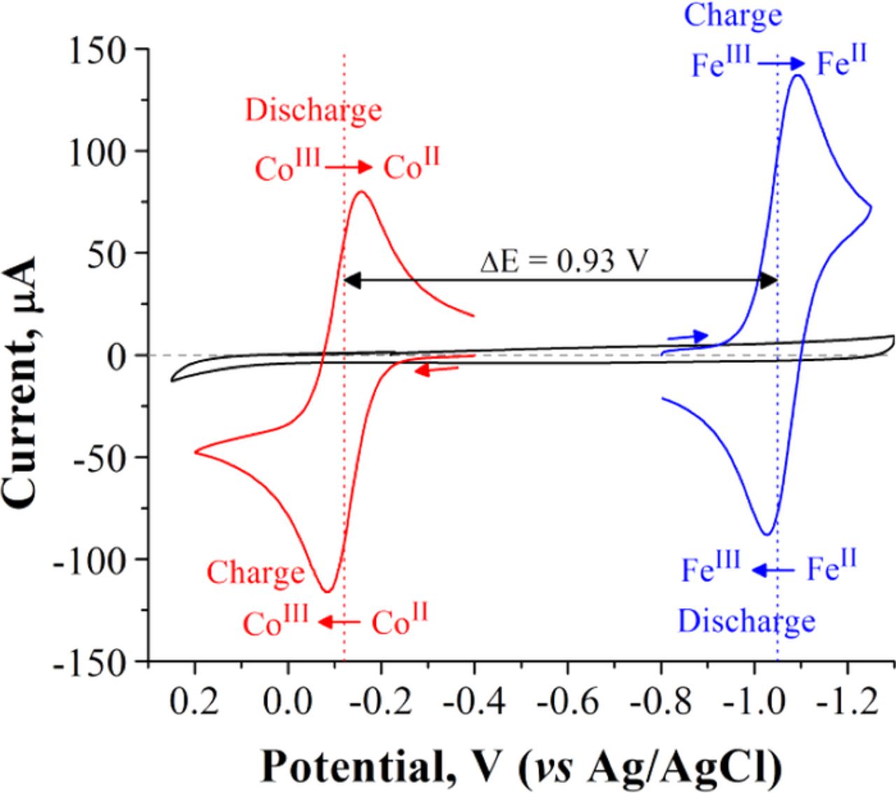
Figure 2. Cyclic voltammograms of 2 mm diameter glassy carbon electrode (black), 20 mM [Fe(TEA)(OH)]− (blue), and 20 mM [Co(mTEA)(H2O)] (red) in aqueous 5 M NaOH. The scan rate is v = 50 mV s−1. The complexes were synthesized using stoichiometric amounts of metal ion and ligand. ΔEpFe-TEA = 60 mV, ΔEpCo-mTEA = 73 mV. E0'Fe-TEA = −1.05 V and E0'Co−mTEA = −0.12 V.
The chemical formula of [Fe(TEA)(OH)]− was determined by single crystal XRD analysis and confirmed by Raman spectrometry coupled to DFT calculations. This work will be discussed in detail elsewhere.19 The chemical formula of [Co(mTEA)(H2O]− is reported from preliminary XRD analysis of a single crystal included as supporting information (Figure S2). Both reactions are diffusion controlled (see Figures S3 and S4), outer-sphere heterogeneous electron transfer processes. Reaction 1 is electrochemically reversible16 with ΔEp = 60 mV, whereas reaction 2 is quasireversible with ΔEp = 73 mV.
Bulk electrolysis
The number of electrons transferred in each reaction was determined by controlled potential coulometry, Figure 3. The electrolysis cell was calibrated using ferrocenemethanol (FeMeOH) as a standard (Figure S5). The reduction of [Fe(TEA)(OH)]−, reaction 1, carried out past the cathodic CV peak at −1.15 V showed Qexp/Qtheo = 0.98 at t = 700 s, using Qtheo = nFVC*, where n = 1 is the number of electrons, F is Faraday's constant, V is the solution volume, C* is the initial concentration of analyte, and Qexp = 4.51 C (Fig. 3A). The current decayed smoothly to the background value and a plot of log(i) vs. t yielded a straight line (Fig. 3B).20 Reverse electrolysis carried out at −0.8 V consumed approximately the same number of coulombs as the forward electrolysis (4.89 C). Such results are only valid for concentrations of [Fe(TEA)(OH)]− ≤10 mM. At concentrations higher than 10 mM, the reduction of [Fe(TEA)(OH)]− follows an EC reaction scheme:19
![Equation ([3])](https://content.cld.iop.org/journals/1945-7111/162/3/A378/revision1/jes_162_3_A378eqn3.jpg)
where kf ≈ 2.0 ± 0.8 × 10⁻⁴ M−1 s−1. The dinuclear compound produced after the condensation reaction 3 is electrochemically active at the same formal potential of [Fe(TEA)(OH)]−, but only gives one electron back:
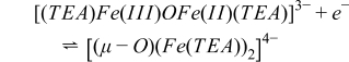
The mixed valence compound [(TEA)Fe(III)OFe(II)(TEA)]3− is the chemically stable form of the oxidation product of [(μ-O)(Fe(TEA))2]4− at concentrations ≈ 0.5 M. This indicates that at least 2 moles of Fe(II) per mole of Co(III) must be used in the battery. Oxidation of [Co(mTEA)(H2O)]−, reaction 2, was carried out past the cathodic CV peak at 0.2 V and showed Qexp/Qtheo = 1.0 at t = 427 s (Fig. 3C). The current-time curve also decayed smoothly to background and a plot of log(i) vs. t yielded a straight line (Fig. 3D). Reverse electrolysis of the solution at −0.4 V consumed the same number of coulombs as the forward electrolysis (0.52 C). These results confirmed that reactions 1 and 2 involve the transfer of one mole of electrons per mole of complex.
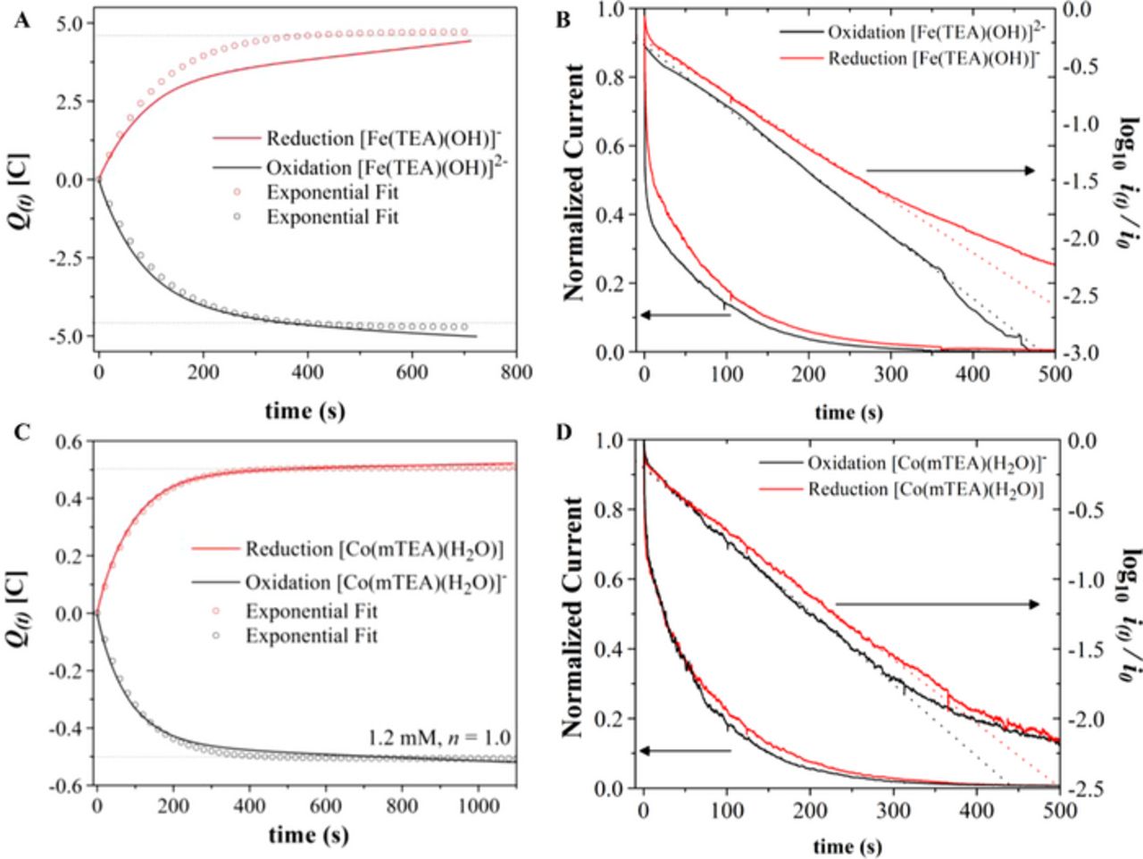
Figure 3. A, C. Plots of charge (coulombs) vs. electrolysis time constructed from the current-time curves corresponding to 10 mM [Fe(TEA)(OH)]− and 1.2 mM [Co(mTEA)(H2O)]− in aqueous 5 M NaOH. Volume = 4.5 mL. B, D. Current-time and log10 (current)-time curves during exhaustive electrolysis of the same solutions at a reticulated vitreous carbon electrode.
Solubility in 5 M NaOH
TEA is soluble in 5 M NaOH to ≥ 2.0 M, whereas mTEA was ≥ 1.5 M. Solutions of [Fe(TEA)(OH)]− can be prepared with a stoichiometric metal-to-ligand ratio of 1:1 up to 0.5 M. By adding excess ligand in ratios of 1:1.5 or higher, the solubility can be increased up to 0.8 M. Concentrations of [(μ-O)(Fe(TEA))2]4– up to 0.325 M can be achieved by maintaining a metal-to-ligand ratio of 1:2 during the synthesis. Solutions of [Co(mTEA)(H2O)]− can be prepared in a stoichiometric ratio of 1:1 up to 0.5 M. By adding excess ligand in ratios of 1:1.5 or higher, the solubility can be increased up to 0.7 M. Co(III)-mTEA was only prepared by bulk electrolysis from [Co(mTEA)(H2O)]− and is soluble at the same concentrations.
Charge-discharge cycling performance of the battery
The performance of the Co/Fe alkaline RFB was initially evaluated at low concentrations by constructing charge-discharge curves from constant-current electrolysis experiments and by analyzing the total charge electrolyzed per half-cycle. Figure 4A presents plots of charge vs. half-cycle for the cases (a), (b), and (c) described in Table I. When stoichiometric amounts of Co(II)-mTEA and Fe(III)-TEA were used as electrolytes in the battery, i.e. case (a), we obtained 95.0 C after the initial charging, then the number of coulombs abruptly decayed to 51.5 C in the following discharge (46% decay), and continued decaying in subsequent half-cycles until a steady number around 35.7 C was attained. Figure 4B shows an example of the first charge and first discharge curves obtained in case (a). Case (b) was carried out using equal concentrations of Co(III)-mTEA and Fe(II)-TEA, and achieved 45.4 ± 15 C in all half-cycles (47% of total coulombs). Interestingly, the first discharge gave 55.4 C, approximately the same number of coulombs as the first discharge in case (a). Finally, in case (c), the negative electrolyte was composed of 50 mM Fe(III)-TEA and 110 mM Fe(II)-TEA with 50 mM Co(II)-mTEA. This last experiment with a mole ratio of Fe/Co of 3.2 gave 96 ± 3 C in all 25 half-cycles.
Table I. Conditions Used for the Evaluation of Battery Performancea,b.
| Case | Volume | Positive Electrolyte | Negative Electrolyte | Coulombsc | Fe/Co |
|---|---|---|---|---|---|
| a) | 20 mL | 50 mM Co(II)-mTEA | 50 mM Fe(III)-TEA | 96.48 C | 1.0 |
| b) | 20 mL | 50 mM Co(III)-mTEA | 50 mM Fe(II)-TEA | 96.48 C | 1.0 |
| c) | 20 mL | 50 mM Co(II)-mTEA | 50 mM Fe(III)-TEA + 110 mM Fe(II)-TEA | 96.48 C | 3.2 |
| d) | 3 mL Co 6 mL Fe | 0.5 M Co(II)-mTEA | 0.25 M Fe(III)-TEA + 0.5 M Fe(II)-TEA | 144.72 C | 3.0 |
aSoC = 0% in all cases. bCurrent density japp = 21 mA cm-2 in cases (a), (b), and (c). Case (d) used japp = 30 mA cm-2. cTheoretical number of coulombs from moles of limiting reagent.
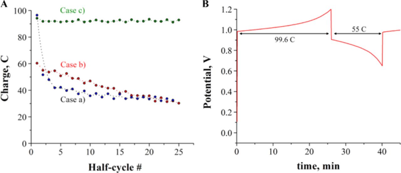
Figure 4. A. Plots of number of coulombs vs. half-cycle number extracted from constant-current electrolysis of the systems described in Table I. Initial SoC = 0%. B. Example of first charge and first discharge curves obtained in case (a). Positive electrolyte: 20 mL of 50 mM Co(II)-mTEA in 5 M NaOH; Negative electrolyte: 20 mL of 50 mM Fe(III)-TEA in 5 M NaOH; 50 μm thick Nafion membrane; flow rate: 40 mL min−1; current density: 21 mA cm−2.
Experiments carried out with concentrations 0.5 M, case (d) in Table I, are shown in Figure 5. The charge-discharge data was collected by cycling from SoC = 0% to SoC =100%. Figure 6 shows coulombic and energy efficiencies achieved every cycle in Figure 5. The efficiencies are calculated as follows:
![Equation ([4])](https://content.cld.iop.org/journals/1945-7111/162/3/A378/revision1/jes_162_3_A378eqn5.jpg)
![Equation ([5])](https://content.cld.iop.org/journals/1945-7111/162/3/A378/revision1/jes_162_3_A378eqn6.jpg)
where ηQ is coulombic efficiency, Q is charge in coulombs, ηE is energy efficiency, and  discharge and
  charge are the average voltage during discharging and charging, respectively. In Figure 5, the initial open circuit voltage (OCV) is 0.7–0.9 V. Charging at 30 mA cm−2 achieved a full cycle every 42 min, with average coulombic efficiency in any single cycle of ηQ = 99%, at a cut-off cell voltage of 1.25 V. The upper cut-off voltage was not exceeded in order to prevent deposition of magnetite10 on the carbon electrodes. The OCV at SoC ≥ 98% is 0.95 to 1.00 V. The cut-off cell voltage for the discharge was set to 0.40 V. The average energy efficiency in all cycles was ηE = 71%.
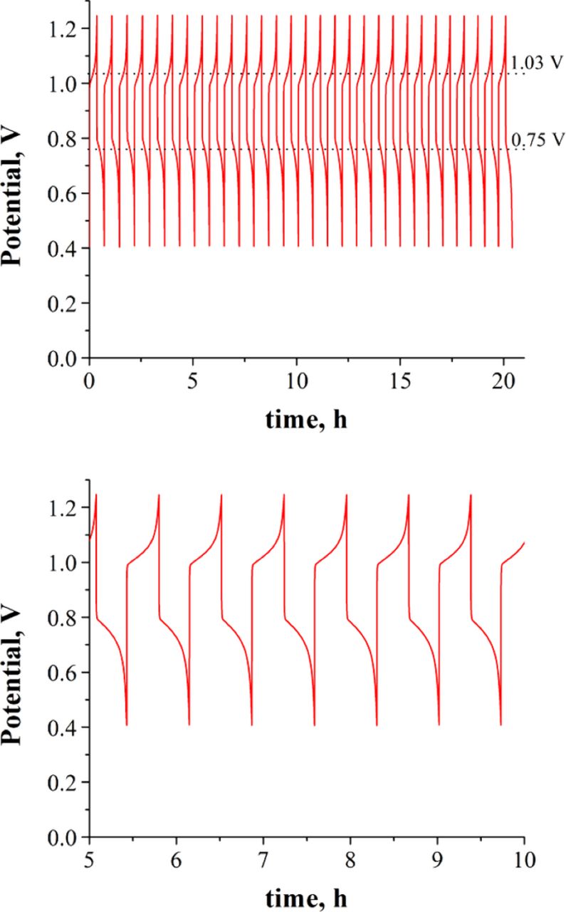
Figure 5. Top. Charge-discharge cycling curves of the Co/Fe alkaline RFB with the following conditions: Positive electrolyte: 3 mL of 500 mM Co(II)-mTEA in 5 M NaOH; Negative electrolyte: 6 mL of 500 mM Fe(II)-TEA and 250 mM Fe(III)-TEA in 5 M NaOH; 50 μm thick Nafion membrane; flow rate: 140 mL min−1 for Co-mTEA and 200 mL min−1 for Fe-TEA, current density: 30 mA cm−2. Charging from SoC = 0% to SoC =100%. Bottom. Zoomed-in region between t = 5–10 hours.
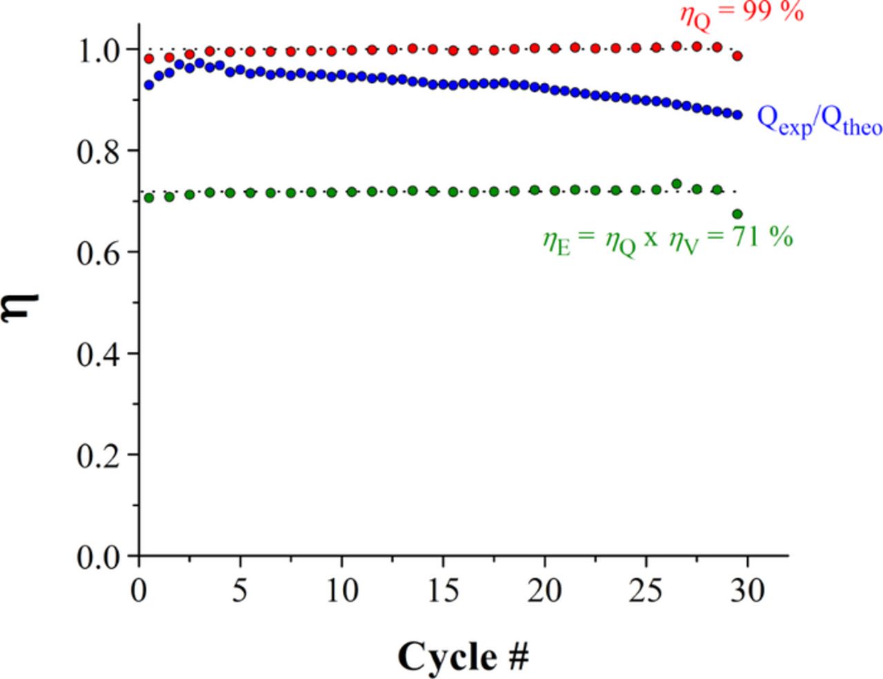
Figure 6. Plots of efficiency, η, vs. cycle number recorded from the constant-current analysis in Figure 5. Each red point corresponds to coulombic efficiency, ηQ, as calculated from equation 4. The green dots correspond to energy efficiency, ηE, calculated from equation 5. Blue dots are the ratio of experimental coulombs over theoretical coulombs.
Discussion
Solubilities in 5 M NaOH
We start our discussion by indicating that the use of excess ligand during the synthesis of the Fe-TEA and Co-mTEA complexes does not appear to change the coordination chemistry in solution (CV's are identical to 1:1 ratios, see Figure S3), but it does increase the viscosity of the electrolyte. Moreover, the synthesis of [Fe(TEA)(OH)]− consumes OH−, and TEA will deprotonate (pKa = 14.1)21,22 when coordinated with iron, further decreasing [OH−]. Hence, it is important to keep a molar excess of OH− in solution to prevent the formation of other species that are favored at pH < 14. In the case of [Fe(TEA)(OH)]2−, excess ligand is always needed to favor the complexation of Fe2+ with TEA (because βFe(II) ≪ βFe(III)).
Charge-discharge cycling performance of the battery
Based on the results presented so far, the cell notation for the charged state of the Co/Fe alkaline RFB is:
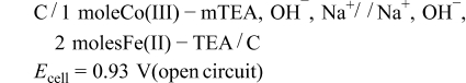
A schematic representation of the flow battery with these conditions is shown in Figure S6. In the experiments presented in Figure 5, the stoichiometric ratios between the two electrolytes were adjusted on a volume basis, using Co(II)-mTEA as the limiting reagent. We used 0.5 M Co(II)-mTEA in 3 mL as the positive electrolyte. The negative electrolyte was composed of 0.5 M Fe(II)-TEA + 0.25 M Fe(III)-TEA in 6 mL. This was done to start the cycling experiments by charging the battery. When preparing the negative electrolyte, Fe(II)-TEA and Fe(III)-TEA were prepared independently, and then added together to form the final solution. Synthesis of both complexes in the same reaction mix yields a black precipitate (iron oxides).23 Moreover, we have determined that the main source of ohmic drop in our system is the Nafion membrane, due to the poor conductivity of Na+ from the 5 M NaOH electrolyte. At a constant current density of 30 mA cm−2, the membrane resistance accounts for iR = 0.2 V during charge-discharge cycling. Such a resistance limits the overall efficiency of our battery. We plan to test other membranes in the future. Importantly, less than 5% crossover was observed at the end of the experiments (after 30 cycles, as determined by CV). To the best of our knowledge, Fe-TEA and Co-mTEA are the first chemistries to present crossover <5% in such a number of cycles. However, a decrease of 10% in the capacity of the battery was observed after the 30th cycle. The change in capacity over time is attributed to O2 leaking into the flow lines (see section S7 of supporting information), the 4% crossover, and a net change in the volume of the electrolytes equivalent to 0.04 Vinitial that diluted the Co-mTEA electrolyte. Different strategies were tested to minimize the oxidation of Fe(II)-TEA by O2, and Figures 5 and 6 show our best operating conditions. The system could be improved by replacement of the plastic tubing with other materials (like stainless steel or glass). No precipitation of products or evolution of gases was observed during charge-discharge cycling at the higher concentration conditions (>10 mM).
As a conclusion, we have introduced the first redox flow battery based on the coordination chemistry of iron and cobalt with amino-alcohol ligands in strong base. We selected the redox couples Co(III/II)-mTEA and Fe(III/II)-TEA because they can be prepared from inexpensive salts of transition metal ions and organic ligands.24 The electrochemistry of the system was characterized by voltammetry, chronoamperometry, and bulk electrolysis. The conditions of the battery were optimized to achieve energy efficiencies of 70–76% at current densities of 30 mA cm−2. More importantly, significant species crossover was not observed in up to 30 charge-discharge cycles, a significant improvement over existing commercial technologies that are known to deactivate due to crossover (e.g. vanadium systems,25 and Fe/Cr systems).
Supporting information available
Additional experimental data is provided as supporting information.
Acknowledgments
The information, data or work presented herein was funded in part by the Global Climate and Energy Project (27777240–51978A) [AJB]. We thank the Welch Foundation (F-816) and ACS-PRF (52682-ND10) for support [RAJ].
N.A.C. developed the alkaline redox flow battery. He identified the coordination compounds, carried out a systematic study of the complexes to find the most appropriate candidates for the battery, and collected all the electrochemical data. J.W.H. carried out the inorganic characterization of the complexes. He grew crystals, carried out XRD analysis of the structures and simulated Raman spectra in solution. He helped to uncover the mechanism of Fe(III)-TEA. J.E.D. assisted in the collection of electrochemical data, and carried out the UV-Vis experiments. R.A.J. and A.J.B. were the two P.I.'s involved in the project, and contributed intellectually to the development of the alkaline flow battery.
The authors declare no competing financial interests.