
Abstract
Within the research and the development of protective carrier platforms intended for oral drug delivery, polymeric microreservoir devices with sizes around 300 μm have been proposed as a delivery system capable of unidirectional drug release. So far, microreservoir devices have been fabricated with simple shapes by means of high-throughput fabrication methods. In this feasibility study, state-of-the-art micro-stereolithography 3D printing is used for the fabrication of various microreservoir geometries. Scanning electron microscopy characterization and conducted resolution tests demonstrated the capability of the used technology and unveils challenges and opportunities associated with the proposed fabrication process.
Export citation and abstract BibTeX RIS

This is an open access article distributed under the terms of the Creative Commons Attribution 4.0 License (CC BY, http://creativecommons.org/licenses/by/4.0/), which permits unrestricted reuse of the work in any medium, provided the original work is properly cited.
When administered orally, many important drugs, such as insulin, reveal poor absorption efficiencies. This problem has triggered a lot of interest within the pharmaceutical and related sciences in developing mechanisms that could help to overcome the barriers that restrict efficient oral delivery. The necessity to realize the oral administration in those cases is mainly driven by the fact that the oral route exhibits several advantages, including increased patient compliance and in general its less invasive nature, compared to alternative drug delivery methods comprising the parenteral, nasal, transdermal, pulmonary, rectal and vaginal routes. In case of inefficient oral drug delivery, the restrictions are set by the nature of the gastrointestinal system. The presence of hydrochloric acid associated with a harsh decline in pH down to 1.5, proteolytic and other digestive enzymes and finally a tightly arranged mucus-secreting epithelial cell layer prove to be very efficient barriers against the delivery and absorption of functional molecules.
Within the research areas of nano- and microtechnology, different platforms, e.g. nanoparticles, microparticles and liposomes, but also engineered microfabricated reservoir devices have been developed and tested with promising results as bioavailability-enhancing carrier systems.1,2 A carrier system ideally provides resistance against enzymes and pH-gradients, a stable and biocompatible environment, a permeability enhancing effect, a prolonged release pattern and a non-toxic/biosafe profile.3 In contrast to particulate systems, in which the drug loading efficiency also depends on the molecular interactions between the drug and encapsulating molecules, microfabricated reservoir devices represent universal carrier platforms, that can be loaded with different drugs.
Besides oral drug delivery, additive manufacturing also represents a heavily debated topic in recent time, and it is steadily gaining more popularity largely in the areas of mechanical and manufacturing engineering as well as rapid prototyping of solid three-dimensional macro parts made of various materials. However, additive manufacturing meanwhile also draws increasing interest for the fabrication of three-dimensional structures at the micro- and nanoscale.4 In this respect, additive manufacturing becomes a promising tool to be used in micro- and nanotechnology.
Microfabricated reservoir devices, intended for the oral delivery of drugs, have the advantage of an asymmetric design, which in turn allows for a unidirectional release of the loaded drug, potentially promoting increased release toward the intestinal mucosa.2
Previously, polymeric microreservoir devices, termed microcontainers, have been fabricated by lithography- or hot-embossing-based procedures, which allow for a high throughput, but which are also limited in terms of geometric freedom for container-shape.5,6 The presented work investigates the feasibility of employing additive manufacturing/3D printing technology for the microfabrication of polymeric microcontainers with various geometrical shapes. For this purpose, an Acculas BA-30 micro-stereolithography instrument was employed, thus illustrating the utilization of state-of-the-art high-resolution additive manufacturing technology.
Experimental
Generation of microcontainer designs
The topology optimized design was created by solving a heat conduction problem subject to a volume constraint as presented previously.7
All other designs were programmed in OpenSCAD open-source software.
3D printing of microcontainers
3D printing files were prepared with Magics software (Materialise NV, Belgium). The generation of support structures was omitted as all designs exhibited only short overhangs with sufficient overhang angle. This was further beneficial as post-printing support removal was considered to be difficult up to impossible at the given dimensions. All 3D prints were conducted using a D-MEC Acculas BA-30 micro-stereolithography system (D-MEC LTD., Japan) with a laser spot size and a layer thickness of each 30 μm. After completing the 3D printing procedure, printed structures were immersed in isopropanol for 5 min using a spray bottle and dried with pressurized air.
Scanning electron microscopy of samples
All microscopy was performed using a JSM-6510 Series scanning electron microscope (JEOL Ltd., Japan).
Results and Discussion
In the course of this work, the applicability of micro-stereolithography (μSLA) 3D printing for the fabrication of microcontainers for oral drug delivery was investigated. In this way, the technology was confronted with designs of varying complexity and also with different design dimensions in order to push the technology to its limit and to determine at which dimensions the smallest features can be obtained with the highest level of detail. The first section in this paper describes the fabrication of a complex microcontainer geometry which resulted after employing a topology-optimization algorithm.
Fabrication of complex three-dimensional micro-structures
A microcontainer design with everting micro-pillars from which even smaller pillars are branching out was created using a topology-optimization algorithm which solved a heat conduction problem subject to a volume constraint (Figures 1a, 1b, 1g, 1i).7 This design represented the ideal and ultimately desired geometry in this work and apart from technical limitations it should be fabricated within a size range of 300 to 500 μm in diameter. However, in this size range the smallest feature size would be around 6 μm. However, due to the laser spot size of the employed μSLA system, the possible theoretical resolution of the machine is limited to 30 μm. As a consequence, the design was scaled up to an outer container diameter of 2200 μm and the smallest feature size to approximately 30 μm as it can be noted in Figure 1i.
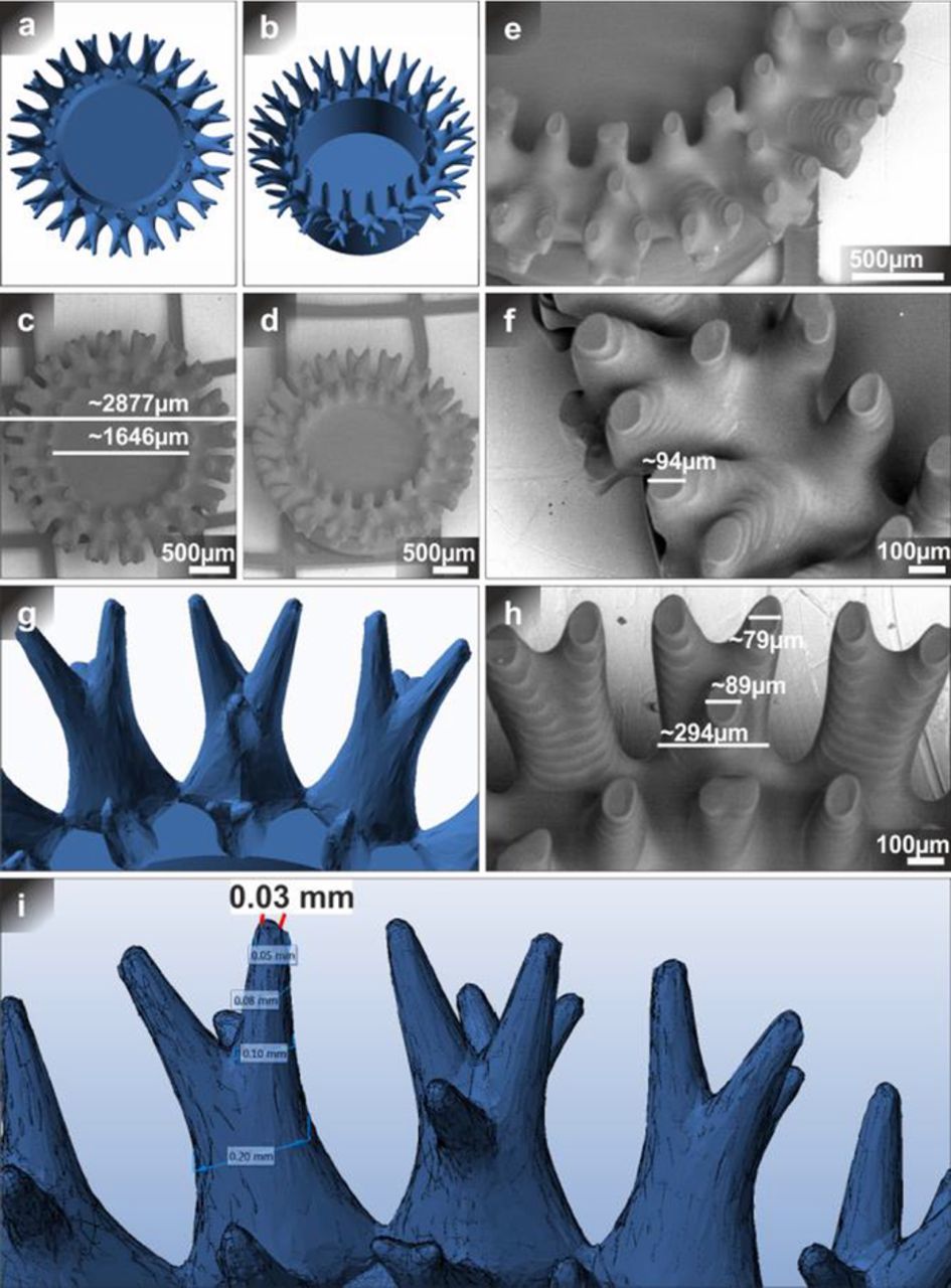
Figure 1. 3D printing of complex topology-optimized microcontainers. SEM images of 3D printed (micro-stereolithography) microcontainers (c, d, e, f, h) and STL-file (a, b, g, i) images of the corresponding complex microcontainer design with everting micro-pillars which were generated using a topology optimization algorithm. The outer diameter of the container design excluding the pillars (a, b) was 2200 μm, including the pillars 2980 μm. The inner diameter was 1800 μm and the height 1000 μm. Observed sizes are depicted in the SEM images and theoretical measurements of the micro-pillars in the STL-file are illustrated in (i). Images (d, e, f, h) were recorded at a tilted angle of 35°.
When comparing the overall appearance and dimensions of the scanning electron microscopy (SEM) images (Figures 1c, 1d, 1e, 1f, 1h) of the resulting 3D printed object, it can be recognized that the object was not fully defined and that the dimensions were deviating from the specifications given by the design. The outer diameter of the whole object was 3.5% and the inner diameter 8.6% smaller. Upon inspection of the pillars it became noticeable that single lithographic layers (Z-direction) were visible and that the pillars were not entirely printed in the object, which means that the basic structure was laid out in any case, but the smallest features were missing. This leads to the conclusion that the fabrication of the pillars stopped at some point because a threshold to what was technically possible was reached. The measurements of the tips of the pillars in comparison to the theoretical measurements in the design suggest that approximately only 80% of the pillars, up to a diameter of approximately 80 μm, were fabricated. Since in the design the pillars are directed outwards from the object, the unfinished pillars could also be an explanation for the smaller outer diameter of the object. Finally, another remarkable finding is that the reservoir of the container is not clearly recognizable and seems to be filled. This circumstance could have resulted from improper removal of excess uncured resin residue.
Fabrication of simple three-dimensional micro-structures
Since the complex microcontainer design presented in the previous section could not be 3D printed with a satisfactorily outcome, a new design with a much lower level of complexity was introduced and additively manufactured (Figure 2). In contrast to the previous design, the minimum feature size was increased to 80 μm whereas the overall size was reduced to 500 μm. Contradictory to the expectation that a simpler design and an increased minimum feature size would lead to an improved print outcome, the microcontainer depicted in Figures 3b and 3c exhibited a rather bulky appearance with a measured minimum feature size which was about 42.5% larger as specified by the design. In contrast to the complex microcontainer, no single lithographic layers could be observed. The gained findings suggest that the dimensions used in this design, especially the minimum feature sizes were too small to obtain acceptable results with the used instrument.
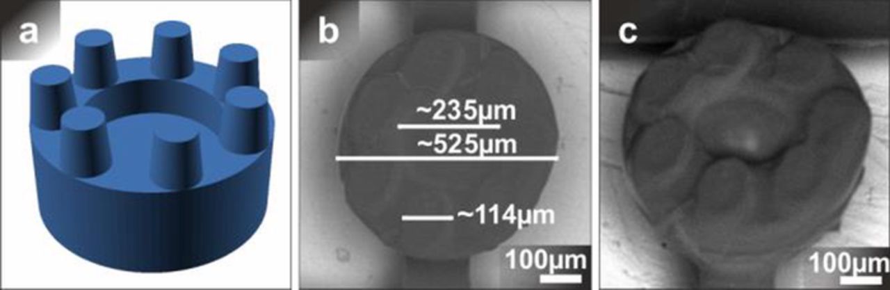
Figure 2. 3D printed simple microcontainers at small scale. SEM images of 3D printed microcontainers (b, c) and STL-file (a) images of the corresponding microcontainer design made with OpenSCAD software. The outer diameter of the container design (a) was 500 μm, the inner diameter 300 μm. The micro-pillars had a bottom diameter of 100 μm, a top diameter of 80 μm, a height of 100 μm and a pitch of 80 μm. The image (c) was taken from a 35° tilted angle.
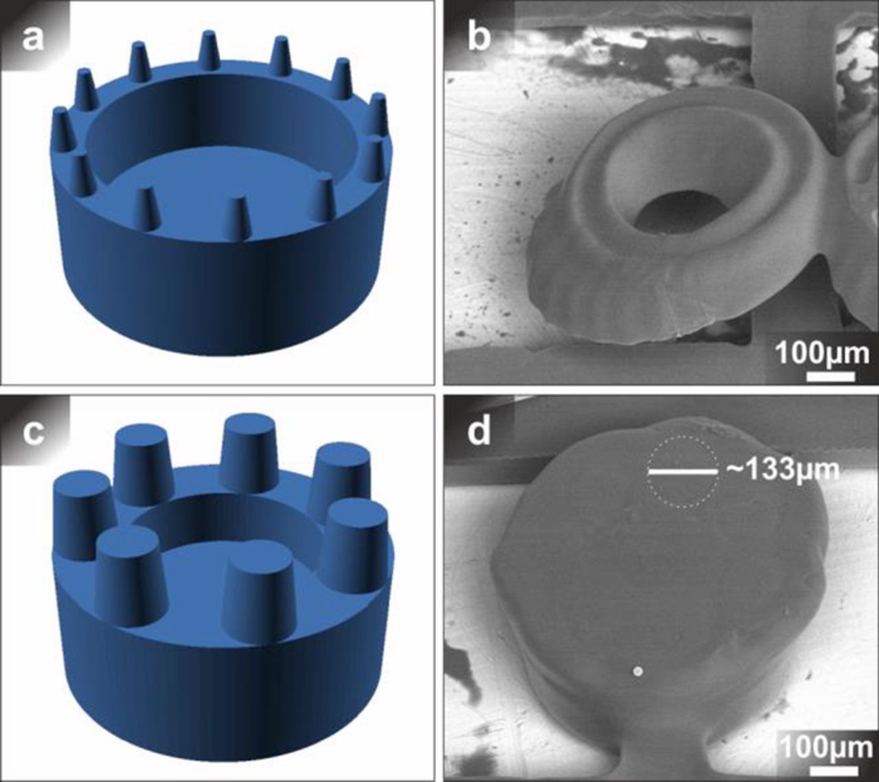
Figure 3. Simple microcontainers 3D printed with differing laser parameters. 3D representations of design-files in STL format (a, c) and SEM images (b, d) of 3D printed microcontainers, where structure (b) is corresponding to model (a) and (d) to (c), respectively. The STL-files featured dimensions of 500 μm in total diameter and pillar dimensions of 20 μm top-diameter and 40 μm base-diameter (a), as well as 80 μm top-diameter and 100 μm base-diameter (c). The height of the micro-pillars was set as 60 μm in (a) and 100 μm in (c). Structure (b) was printed using a decreased laser power of 1 mW for the outline of the object and 4 mW for the infill of the object. Contrary, the structure displayed in (d) was printed with an increased laser power of 4 mW for the outline and 8 mW for the infill. Laser power parameters used in all other experiments were 3 mW (outline) and 5 mW (infill). The SEM-images were recorded from a 35° tilted angle.
Influence of laser power on print quality
In the previous sections the 3D printing of complex and simple microcontainer designs have been described, respectively. As the printing outcome was neither satisfying in case of the complex model nor in the case of the simple model, a short test on the influence of laser power on the print quality was performed. The 3D printing instrument uses two different laser parameters. One laser power value for the outline of the printed structure and one laser power value for the infill of the printed structure. In the first test (Figures 3a, 3b), the laser power was decreased by 66% for the outline, reaching a power value of 1 mW, and by 20% for the infill, thus reaching a power value of 4 mW, when compared to the previous laser settings (outline: 3 mW; infill: 5 mW). The exemplary SEM-image reveals that the structures were not fully printed as the bottoms of the microcontainers were missing and no micro-pillars were visible. Additionally, the print obviously shifted in horizontal direction which means that the cylindrical shape of the microcontainer was distorted. In the second test (Figures 3c, 3d), the laser power was increased by 33% for the outline (4 mW) and by 60% for the infill (8 mW). In this case, the obtained microcontainers exhibited correct cylindrical shape, however, the structures had a rather bulky appearance. The reservoir of the microcontainer was not visible and shapes of micro-pillars could only be detected in a very rudimentary way.
In conclusion, these results suggest that in the first test the laser power was too low. As a consequence of this fact, the print resin was not fully cured and ultimately the structures of the object did not emerge. Contrary to this, in the second test the laser power was obviously too high so that more resin was cured than it was supposed to and then the reservoir as well as the interspace between the micro-pillars was closed. Since the 3D printer was considered to be appropriately calibrated before these tests, it was decided to use the previous laser parameters and not to focus on optimizing laser power any further. Also, in this case, no lithographic layers were visible.
Fabrication of simple but larger three-dimensional micro-structures
As described before, the 3D printing of microcontainers with highly detailed and small features could not be successfully accomplished. In order to improve the print quality, the dimensions of the design were increased, and an overhang was added so as to enlarge the available space for the placement of micro-pillars (Figure 4). In contrast to previous designs, the new design exhibited a container diameter of 1000 μm excluding and 1300 μm including the overhang, respectively, and a microcontainer height of 300 μm, which means that the size was doubled in the XY-plane. Samples denoted as (a) and (b) were manufactured. They only differed in the height of their micro-pillars which was 150 μm for (a) and 200 μm for (b), respectively.
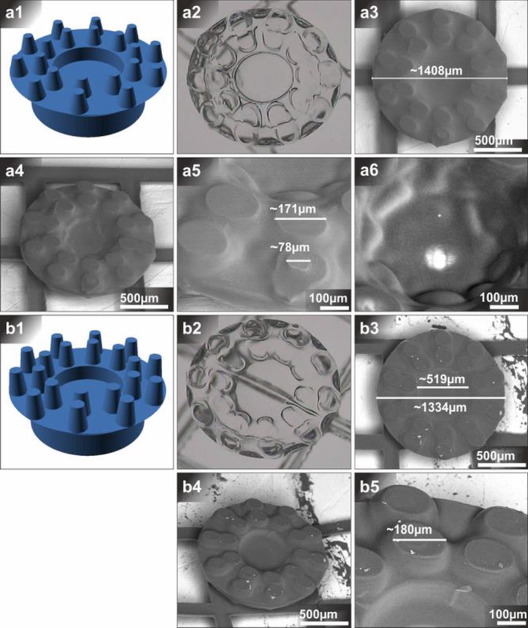
Figure 4. 3D printed micro-containers with overhang and micro-pillars. STL-file representations (a1, b1), optical microscope images (a2, b2) and SEM images of microcontainers. Images (a2) - (a6) are corresponding to model (a1) and (b2) - (b5) to model (b1). (a1) featured an overall diameter of 1000 μm in the bottom and 1300 μm including the overhang. The height of the microcontainers is 300 μm. The featured micro-pillars had a bottom diameter of 150 μm, a top diameter of 80 μm and a height of 150 μm. Model (b1) contained the same dimension parameters, only the height of the micro-pillars was increased to 200 μm. Images (a4) - (a6), (b4) and (b5) were recorded from a 35° tilted angle.
In conformity with the previous results, it can be noted that the obtained small features were larger than it was specified in the CAD model. For (a) samples, the outer diameter including the overhang was 8.3% larger than specified in the design, whereas the top diameter of the micro-pillars was 114% larger. Interestingly, a structure with a size of 78 μm could be found on one of the pillars. If this was the tip of the micro-pillar, it would fit the 80 μm given by the design very closely. However, the fact that this structure could only be found on one of the micro-pillars makes it more likely that it was a print artifact. Additionally, it can be noted that the bottom diameter of the pillars was drastically larger than the 150 μm specified by the design in any case. Other remarkable findings were related to the fact that the distance between the inner micro-pillars and the outer micro-pillars placed on the overhang was not homogenous, since some pillars seem to be connected while others seem to be clearly separated. Also, the cavity was undefined and bumpy and only showed a clear outline in the light microscopy image.
As far as the (b) samples were concerned, the outer diameter including the overhang was 2.6% larger and the top diameter of the micro-pillars was 125% larger than defined by the CAD model. The appearance of samples (b) was similar to that of (a) and the change in the micro-pillars' height showed no noticeable effect. In contrast to (a), only the outline of the cavity was more defined for (b) samples. For both types of samples, no single lithographic layers could be detected as it was the case with the two previously presented experiments.
In summary, the described samples showed that the dimensions of small features, micro-pillars in this case, highly deviated from the specifications that were given by the design parameters, while larger features (e.g. outer diameter of container) deviated less.
Resolution assays
Proceeding from the previous experiments, more systematic resolution testing was conducted. A microcontainer base structure with fixed dimensions was defined and then arrays of microcontainers with differently sized micro-pillars were additively manufactured (Figure 5). It has to be stressed that these experiments were mainly focused on the print outcome of the micro-pillars as an indication for print resolution. The basic structure consisted of a microcontainer with an outer diameter of 1300 μm including and 1000 μm excluding overhang, an inner diameter of 600 μm, a height of 500 μm and a micro-pillar height of 200 μm. The micro-pillar diameters varied from (a) to (f), starting with a top diameter of 30 μm and a bottom diameter of 80 μm for (a) and changing to values of 60/100, 80/130, 100–170,120/200, 90/200 μm for the other iterations.
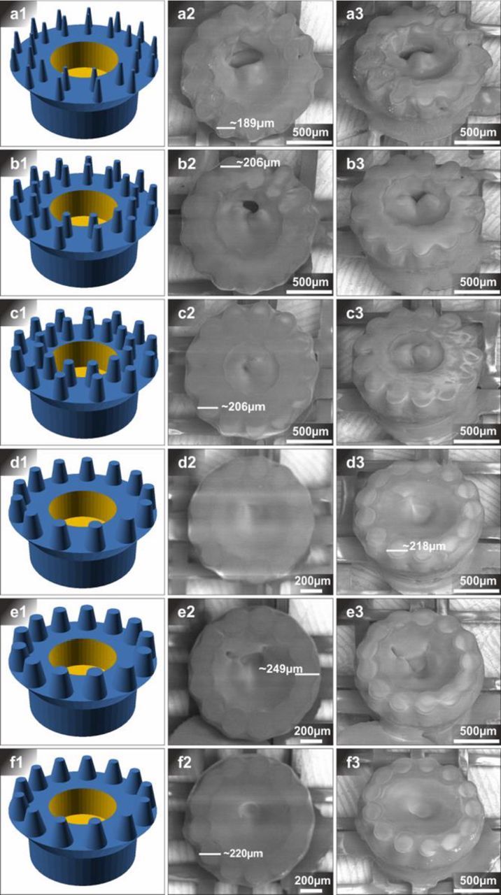
Figure 5. Resolution assay 1: effect of micro-pillar dimensions on print outcome. STL-file models (a1-f1) and SEM images (a2-f2, a3-f3) of microcontainers with differently sized micro-pillars placed on overhang. All STL-models featured an overall diameter of 1000 μm in the bottom and 1300 μm including overhang. Excluding the pillars, all microcontainers had a height of 500 μm. The dimensions of the micro-pillar top- and bottom diameters were as follows: (a1) 30 μm-80 μm, (b1) 60 μm-100 μm, (c1) 80 μm-130 μm, (d1) 100 μm-170 μm, (e1) 120 μm-200 μm and (f1) 90 μm-200 μm. The height of the micro-pillars was set to be 200 μm. SEM images (a3-f3) were recorded from a 35° tilted angle.
The SEM images of printed microcontainers showed structures that appear to be very different than the CAD models. The cavities of the microcontainers seemed to be at least partly filled and the pillars were not clearly separated. In this way, the print outcome of the first experiment reveals a very poor efficiency of the post-print cleaning process, since all containers and especially all micro-pillars and cavities were obviously covered with leftover of uncured resin material. Despite the blurry and undefined appearance, some indications on the shape of the micro-pillars could be observed. When taking these indications into account and comparing the dimensions of the probable pillar diameters with the dimensions from the CAD model, it becomes apparent that, in accordance with all previous experiments, there is a strong deviation between these dimensions, because the printed pillars were larger in all cases. Though, the extent of size deviation was dependent on the pillar size, as from smaller to larger pillars, the print outcome was 6.3 (a), 3.4 (b), 2.6 (c), 2.4 (d), 2.2 (e) and 2.1 (f) times larger. When comparing the CAD drawings with the SEM images of the printed samples it also becomes apparent that there was much less space in between the pillars and that the different samples generally looked much more similar than the CAD-drawings did. Additionally, some samples (a, e and f) show flat structures protruding out of the container base, suggesting that the print shifted in the XY-plane during the print, causing a print defect. In accordance with the previously described experiments, no single lithographic layers were visible.
In the following experiments, the influence of other single parameters on the print outcome was investigated. At first, the pillar height was increased from 200 μm to 300 μm (Figure 6). Also, in this case, the pillars and container cavities were covered with leftover resin. The overall morphologies were similar to those of the previous experiment and no effect of the increased pillar height could be noticed. The size deviation of the pillars followed the same trend as reported before, since the pillars were 6.7 (a), 3.5 (b), 2.9 (c), 2.4 (d), 2.3 (e) and 1.9 (f) times larger than the dimensions given in the CAD-model.
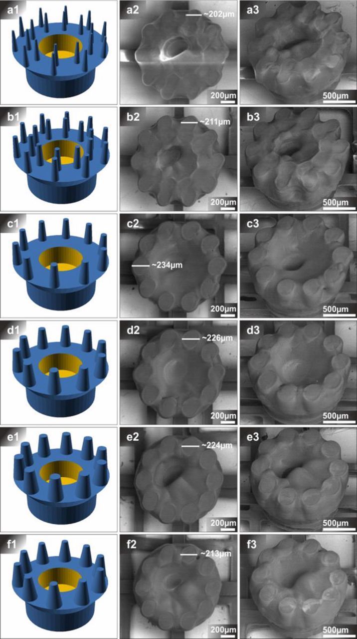
Figure 6. Resolution assay 2: effect on micro-pillar height on print outcome. STL-file models (a1-f1) and SEM images (a2-f2, a3-f3) of microcontainers with differently sized micro-pillars placed on overhang. All STL-models featured an overall diameter of 1000 μm in the bottom and 1300 μm including overhang. Excluding the pillars, all microcontainers had a height of 500 μm. The dimensions of the micro-pillar top- and bottom diameters were as follows: (a1) 30 μm-80 μm, (b1) 60 μm-100 μm, (c1) 80 μm-130 μm, (d1) 100 μm-170 μm, (e1) 120 μm-200 μm and (f1) 90 μm-200 μm. The height of the micro-pillars was set to be 300 μm. SEM images (a3-f3) were recorded from a 35° tilted angle.
In the next step, the overall container diameter was decreased from 1300 to 1000 μm including and from 1000 to 700 μm excluding overhang (Figure 7). As a consequence, the computer algorithm to generate the CAD models placed fewer micro-pillars on top of the containers and increased the space between those. The samples illustrated in (a) and (b) were covered with leftover of uncured resin as it was the case in the previous described experiments. However, in contrast to prior observations, samples (a) and (b) seemed to be covered with less resin, as the uncured material was only connecting the pillars forming a star shape and leaving surface of the microcontainer exposed. In case of the other samples (c-f) even less leftover resin could be observed. Despite the presence of leftover resin on the pillars, the shape of the top diameter could be seen as the pillars displayed a rather shiny surface in the center as compared to the edges. This could be observed best when considering the SEM images taken from an angled perspective. In accordance with prior experiments, the size deviation of the pillars followed the trend of deviating stronger at smaller dimensions, since the pillars were 5.8 (a), 2.6 (b), 3.5 (c), 3.1 (d), 2.6 (e) and 2.5 (f) times larger than given in the CAD drawing. Single lithographic layers were not detected as well. In comparison with the CAD drawings, the cavities were smaller. In case of the sample displayed in (d), the cavity was measured to be 229 μm wide while the CAD-model specified a width of 400 μm. The samples shown in (c) and (e) showed similar print defects as described earlier.
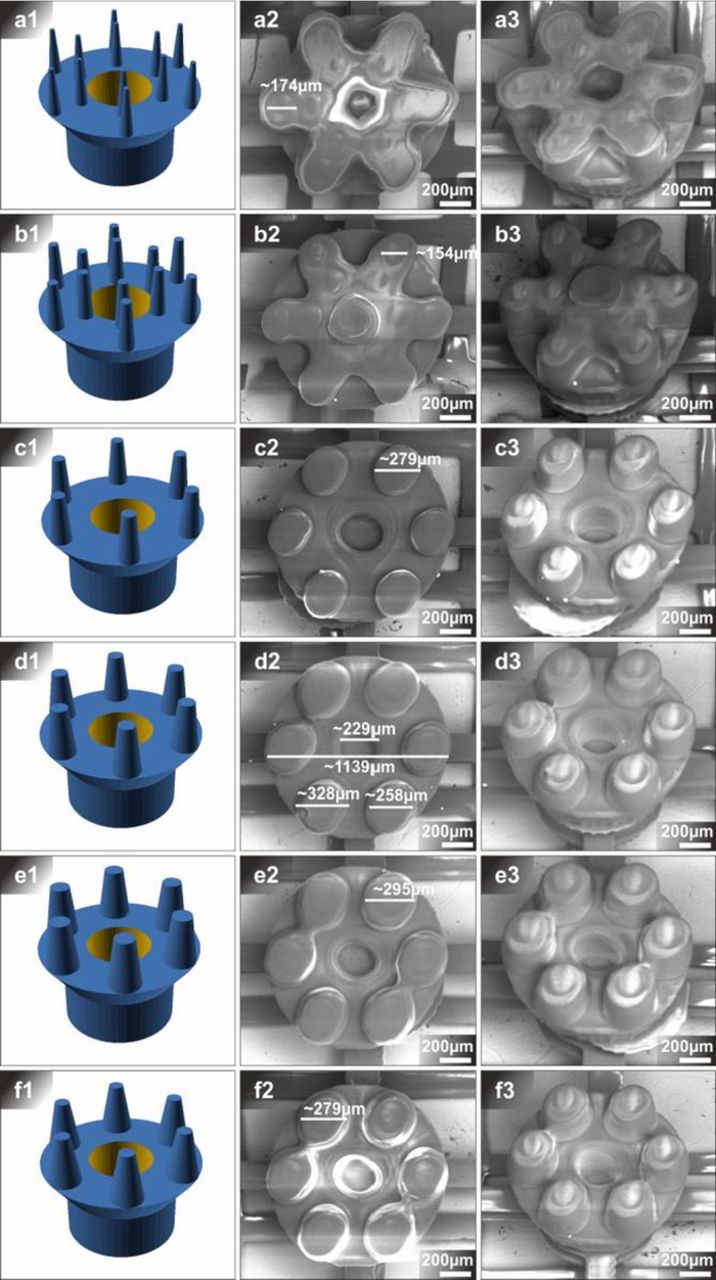
Figure 7. Resolution assay 3: decreasing microcontainer size. STL-file models (a1-f1) and SEM (a2-f2, a3-f3) of microcontainers with differently sized micro-pillars placed on overhang. In contrast to the other figures, all STL-models featured an overall diameter of 700 μm in the bottom and 1000 μm including overhang. Excluding the pillars, all microcontainers had a height of 500 μm. The dimensions of the micro-pillar top- and bottom diameters were: (a1) 30 μm-80 μm, (b1) 60 μm-100 μm, (c1) 80 μm-130 μm, (d1) 100 μm-170 μm, (e1) 120 μm-200 μm and (f1) 90 μm-200 μm. The height of the micro-pillars was set to be 300 μm. SEM images (a3-f3) were recorded from a 35° tilted angle.
In summary, it can be concluded that the change of container overall size did not deteriorate the general print outcome. In contrast, the placement of fewer pillars on top of the microcontainers facilitated a better separation of the pillars and as a consequence the post-print cleaning process probably removed more resin residue than in the other cases.
In the next experiment, the general container height was decreased from 500 to 350 μm and the height of the pillars was decreased down to 200 μm, because the change of pillar height did not show a noticeable effect in prior experiments (Figure 8). The printed microcontainers displayed similar morphologies to those of the previous experiment. In (a) and (b), the leftover resin connected the micro-pillars to form a star shape. However, in these cases the cavities of the containers did not seem to be filled with resin residue while they were still smaller as defined in the CAD models. For example, in (a) the cavity was measured to be 257 μm wide instead of 400 μm as given in the design. The morphologies were not similar with respect to the varying shine of the pillar surfaces that was mentioned earlier. For the samples at hand, no differences were visible. Therefore, close inspection revealed that single lithographic layers were visible at the sides of the micro-pillars in the case of samples (c) to (f). This can be seen best from a tilted angle. With increasing size, the pillars were 6.4 (a), 3.3 (b), 2.9 (c), 2.6 (d), 2.6 (e) and 2.3 (f) times larger than the dimensions given by the design. The differences in morphology, when comparing with previously described results, could not be considered to be associated with the reduction in container and pillar height, since they were probably related to variations in the presence of resin residue.
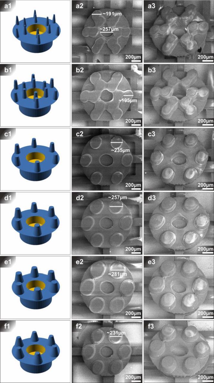
Figure 8. Resolution assay 4: effect of microcontainer height on print outcome. STL-file models (a1-f1) and SEM images (a2-f2, a3-f3) of microcontainers with differently sized micro-pillars placed on overhang. All STL-models featured an overall diameter of 700 μm in the bottom and 1000 μm including overhang. The dimensions of the micro-pillar top- and bottom diameters were: (a1) 30 μm-80 μm, (b1) 60 μm-100 μm, (c1) 80 μm-130 μm, (d1) 100 μm-170 μm, (e1) 120 μm-200 μm and (f1) 90 μm-200 μm. The height of the microcontainers excluding micro-pillars (height = 200 μm) was set to be 350 μm. SEM images (a3-f3) were recorded from a 35° tilted angle.
As a last experiment, the overall diameter of the microcontainers was increased from 1000 μm including and 700 μm excluding overhang to 2000 μm including and 1500 μm excluding overhang (Figure 9). As a consequence of this change, more pillars could be arranged on top of the microcontainer surfaces. The micro-pillars of the samples that are depicted in (a) to (d) were not separated and shared a uniform surface. However, patterns that indicated the shape of the top diameter of the pillars could be found in all cases. Apart from that, the pillars could be recognized when considering the images taken from an angle. These findings suggest that in coherence with the other results, resin residue was covering the pillar structures of the microcontainers. Upon further inspection from the tilted perspective, single lithographic layers could be recognized, not only for the pillars, but also for the container structure. Except from the pillar surfaces which were covered with resin residue, the surfaces of the microcontainers were smooth and the cavities were sharply defined. The measured dimensions of the pillar diameters which are displayed in the SEM images deviated from the dimensions that were defined in the CAD drawings. Beginning from small pillars to large pillars, they were 7.8 (a), 3.9 (b), 3.2 (c), 2.9 (d), 2.6 (e) and 2.1 (f) times larger than specified nominal dimensions. Although the size deviation of the micro-pillars could not be considered to differ a lot from the previous results, the overall print quality of the microcontainers as a whole was improved in this experiment. Additionally, less resin residue could be found.
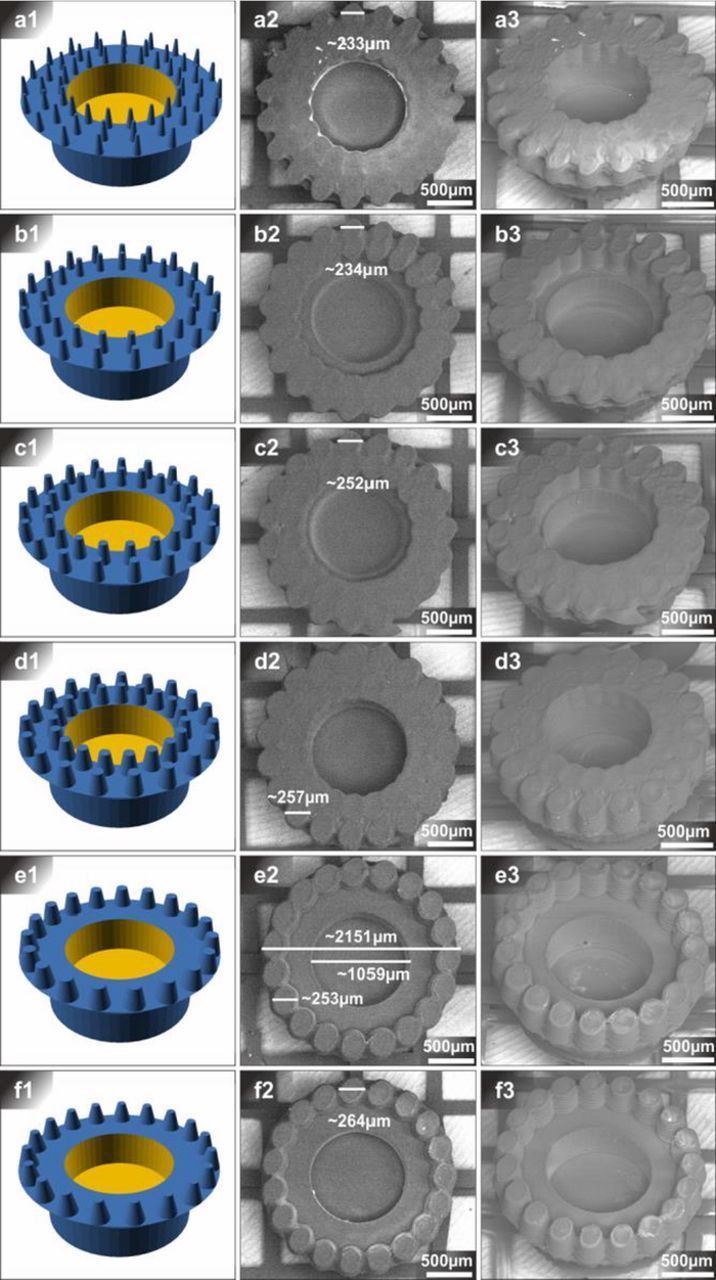
Figure 9. Resolution assay 5: increasing microcontainer overall size. STL-file models (a1-f1) and SEM images (a2-f2, a3-f3) of microcontainers with differently sized micro-pillars placed on overhang. In contrast to the other figures, all STL-models featured an overall diameter of 1500 μm in the bottom and 2000 μm including overhang. Excluding the pillars, all microcontainers had a height of 600 μm. The dimensions of the micro-pillar top- and bottom diameters were: (a1) 30 μm-80 μm, (b1) 60 μm-100 μm, (c1) 80 μm-130 μm, (d1) 100 μm-170 μm, (e1) 120 μm-200 μm and (f1) 90 μm-200 μm. The height of the micro-pillars was set to be 200 μm. SEM images (A-F3) were recorded from a 35° tilted angle.
Conclusions
In this work, challenges and opportunities of using μSLA 3D printing for the manufacturing of various microcontainer geometries were investigated. The reported results showed an obvious deviation between dimensions of the printed structures and the ones given by the CAD models. In general, it could be observed that structures with smaller dimensions deviated more from the defined target values than structures with larger dimensions, thus showing the technical limitations of the employed 3D printing system.
Moreover, it was noticeable that in all experiments, the outcome of the 3D printing was substantially affected by the presence of leftover uncured print resin. The resin filled the reservoirs of the microcontainers and the interspaces between the micro-pillars placed on the edges. While the problem of 3D printing "cups" in stereolithography is a known issue, the post processing of 3D printed structures should accommodate for the removal of excess uncured print resin.8 Under the premise that the post-treatment/cleaning protocol will necessarily need to be the subject of a thorough optimization work, this research demonstrates the feasibility of using μSLA 3D printing to fabricate microcontainers for oral drug delivery since millimeter-sized devices could be realized with this micro manufacturing technology.
From an application point of view a further problem remains. All microcontainers were additively manufactured on a likewise 3D printed grid which irreversibly connected them. However, the working principle of microcontainers for oral drug delivery relies on individually acting containers that attach to the intestinal mucosa. With the current 3D printing method, the release of individual microcontainers is not possible. Therefore, the implementation of 3D printing on a sacrificial release layer as done in micromachining is suggested.9
Acknowledgments
The authors acknowledge the Center for Intelligent Drug Delivery and Sensing Using Microcontainers and Nanomechanics (IDUN) whose research is funded by the Danish National Research Foundation (DNRF122) and Villum Fonden (grant No. 9301). This study was partly supported by the Grant-in-Aid for Scientific Research (Category A, Project no. 17H01224) from the Japan Society for the Promotion of Science (JSPS), the Centre Of Innovation (COI) program from the Japan Science and Technology Agency (JST), the Strategic Innovation Creation Project (SIP) from the New Energy and Industrial Technology Development Organization (NEDO) of Japan, and the Program on Open Innovation Platform with Enterprises, Research Institute and Academia (OPERA) from the JST. The authors would also like to thank Kyuuichiro Takamatsu for operating the 3D printer and Masato Wada for operating the scanning electron microscope.