Abstract
Ionic liquids are attractive candidates as electrolyte solvents for Li-O2 cells, primarily due to their low volatility, high anodic stability, and low flammability. Specifically, the ionic liquid 1-butyl-1-methylpyrrolidinium bis(trifluoromethanesulfonyl)imide (Pyr14TFSI) has attracted considerable attention thanks to its electrochemical and chemical stability. In this work, we demonstrate via our recently developed UV-Vis screening method that Pyr14TFSI unfortunately reacts with the superoxide radical (O• −2) which is produced during the discharge of Li-O2 cells. To clarify the reaction mechanism of O• −2 with Pyr14TFSI, we take advantage of the recently described formation of O• −2 upon contact between lithiated lithium titanate (LTO) and O2 to produce a sufficient amount of degradation products from the reaction of Pyr14TFSI with O• −2 that can be detected by NMR. Furthermore, we validate this new screening method for solvent decomposition by superoxide radicals by investigating the behavior of lithiated LTO in contact with O2 using RRDE voltammetry.
Export citation and abstract BibTeX RIS

This is an open access article distributed under the terms of the Creative Commons Attribution Non-Commercial No Derivatives 4.0 License (CC BY-NC-ND, http://creativecommons.org/licenses/by-nc-nd/4.0/), which permits non-commercial reuse, distribution, and reproduction in any medium, provided the original work is not changed in any way and is properly cited. For permission for commercial reuse, please email: oa@electrochem.org.
Ionic liquids are room-temperature molten salts that have recently attracted considerable attention as electrolyte solvents for energy related applications such as dye-sensitized solar cells, supercapacitors, actuators, thermo-electrochemical cells and batteries.1 Although the properties of ionic liquids vary with their molecular structure, a common feature is their negligible vapor pressure, leading to low flammability and thus, e.g., enhanced battery safety. Furthermore, ionic liquids are attractive due to their high ionic conductivity, low toxicity as well as their high thermal, chemical and electrochemical stability.1,2 In this last category, ionic liquids with cyclic quaternary ammonium cations such as pyrrolidinium or piperidinium have become especially popular due to their outstanding stability at reducing potentials, which renders them suitable for highly negative battery electrodes.3 Even though their cathodic stability is superior to, e.g., imidazolium-based ionic liquids, there are doubts as to whether they are indeed stable at the lithium potential. While Kroon et al.4 and Markevich et al.5 reported the instability of the 1-butyl-1-methylpyrrolidinium cation (Pyr14, often also referred to as BMP or BMPyr) employing quantum chemical calculations, GC-MS and FTIR analysis, others observed high cycling stability for lithium plating6,7 as long as the ionic liquid was sufficiently clean and dry.8,9 Fortunately, the combination with the bis(trifluoromethanesulfonyl)imide anion (TFSI, also abbreviated as (Tf)2N− or NTf2) seems to enhance the stability due to its ability to form a passivating surface film upon electroreduction in the presence of lithium cations, and additionally leads to a desired, relatively low viscosity.5
All these promising properties make Pyr14TFSI not only attractive for Li-ion batteries, but also as an electrolyte solvent for aprotic Li-air batteries, which has been the focus of many recent studies due to the high theoretical specific capacity of its oxygen cathode. It thus has raised hope for a considerable increase in battery energy density, which would enable a substantial range extension of fully-electric vehicles,10,11 a claim, however, which has been seriously questioned in a recent study comparing the energy density of battery systems rather than simply comparing that of battery cells.12 Due to the need for gas as a reactant, the low volatility of the electrolyte solvent is even more important than in conventional lithium-ion batteries. Furthermore, ionic liquids with a TFSI anion attracted early attention for use in lithium-air batteries due to their presumed hydrophobicity, which was hypothesized to decrease moisture intrusion from air to the electrodes.13,14 However, the most important requirement for an electrolyte solvent in Li-O2 cells is, next to the electrochemical stability window, its stability in the presence of oxygen reduction reaction (ORR) intermediates such as the superoxide anion radical (O• −2). This radical occurs as a discharge intermediate that, in the presence of Li+, forms LiO2, which then disproportionates and/or gets further reduced to the final discharge product Li2O2 according to reactions 1–4.15–17
![Equation ([1])](https://content.cld.iop.org/journals/1945-7111/162/6/A905/revision1/jes_162_6_A905eqn1.jpg)
![Equation ([2])](https://content.cld.iop.org/journals/1945-7111/162/6/A905/revision1/jes_162_6_A905eqn2.jpg)
![Equation ([3])](https://content.cld.iop.org/journals/1945-7111/162/6/A905/revision1/jes_162_6_A905eqn3.jpg)
![Equation ([4])](https://content.cld.iop.org/journals/1945-7111/162/6/A905/revision1/jes_162_6_A905eqn4.jpg)
The initial O• −2 has been shown to react with the carbonate-based electrolytes used in most of the Li-air literature prior to 2011,18,19 to yield various alkyl carbonates and formates instead of the desired Li2O2 obtained in reactions 3 and 4. Therefore, most researchers these days employ either ether- or DMSO-based electrolytes20 that seem to be stable against superoxide chemically produced from KO2, at least in the absence of O2 gas.21 However, these solvents suffer from a limited stability against anodic oxidation, which would be superior for several of the above discussed ionic liquids.
In view of this advantage, the suitability of different ionic liquids for metal-air battery application, as measured by their stability toward superoxide radicals, has been studied by voltammetry13,22–26 as well as by tests employing KO224,27,28 or in molecular orbital calculations.25 While imidazolium-based ionic liquids were found to react with O• −2,13,24,25,27 those with quaternary ammonium cations were found to be more stable,13,22,23,25,27,28 which interestingly correlates with their superior electrochemical stability at negative potentials. Thus, piperidinium25,29,30 and pyrrolidinium31,32 based ionic liquids have been employed as electrolyte solvents for initial cycling tests in Li-O2 cell studies. Among these, Garsuch et al. compared cells with carbonate-, imidazolium- and pyrrolidinium-based electrolyes and found that the more stable the solvent, the smaller the discharge capacity.31 This is in agreement with our observation that the discharge capacity is enhanced by adding substances in the electrolyte that are reactive toward superoxide radicals, such as water33,34 or various impurities in commercially-available glymes.21 Although Li2O2 was found to be the main discharge product in the above discussed studies29,30 implementing cyclic-ammonium-based ionic liquids, some Li2CO3 was also detected as a by-product29,30 that may arise from the decomposition of the cathode carbon support or of the electrolyte.35
In an early effort to quantify the O• −2-stability of Li-O2 battery electrolytes, our group developed a technique based on rotating ring disc electrode voltammetry (RRDE)23 that can be used to estimate the reaction rate constant by taking advantage of the diffusion delay for O• −2 produced at the disc and detected at the ring (i.e., of the so-called transient time, Ts).36 When we applied this procedure to quantify the O• −2-stability of Pyr14TFSI,23 no superoxide reaction with the electrolyte was observed within maximum achievable transient time of ≈10 s with this technique.23 Since the time scale of the discharge process in a Li-O2 cell far exceeds these few seconds, we recently developed another method to determine the long-term stability of solvents toward superoxide radicals, which is based on dissolving KO2 in DMSO, adding the solvent of choice, and following the consumption of O• −2 over time by measuring its UV absorbance.21
Motivated by the advantages of Pyr14TFSI, we wanted to unambiguously determine its long-term stability against O• −2 using the above discussed UV-Vis procedure. As will be shown, our data suggest that Pyr14TFSI is not long-term stable against O• −2. Unlike in our previous study,21 the concentration of the decomposition products was too low for detection by NMR after extended stirring of KO2 powder in Pyr14TFSI, which we ascribe to the too low solubility of KO2 resulting in too low concentrations of decomposition products. Therefore, we devised a new method which produces sufficiently high concentrations of O• −2 and thus degradation products, which we could analyze by NMR. This method is based on the reaction between lithiated lithium titanate (LTO) and O2 recently described by our group,37 which leads to the formation of O• −2 through the delithiation of the LTO. This new screening tool for solvent decomposition by superoxide radicals was further validated by investigating the behavior of lithiated LTO in contact with O2 using RRDE voltammetry.
Experimental
UV-Vis spectroscopy to determine the rate constant of the reaction of O• −2 with Pyr14TFSI
The ionic liquid 1-butyl-1-methylpyrrolidinium bis(trifluoromethanesulfonyl)imide (Pyr14TFSI, >99.5%, Iolitec, Germany) employed throughout this work was dried under dynamic vacuum at 120°C in a glass oven (Büchi, Switzerland), which led to a water concentration below the quantification limit by Karl Fischer titration (<1 ppm, Titroline KF, Schott Instruments, Germany). For the quantification of the rate constant k of the reaction of O• −2 with Pyr14TFSI, we employed the recently described UV-Vis spectroscopy screening method.21 In brief, the amount of potassium superoxide (KO2, 96.5%, Alfa Aesar, used as received) required to obtain a 3 mM solution was stirred in dimethyl sulfoxide (DMSO, 99.99%, Sigma Aldrich, dried over Sylobead MS 564C zeolites (3 Å, Grace Davison, USA)) for 90 min in an argon-filled glovebox (O2 < 0.1 ppm, H2O < 0.1 ppm, MBraun, Germany) to ensure complete dissolution. 0.7 ml of the obtained solution was pipetted into a sealed quartz cuvette (1/ST/S/Q/2 mm, Starna, Germany) that was then transferred out of the glovebox and mounted in a UV-Vis spectrometer (Lambda35, Perkin Elmer, USA) to record a spectrum to determine the absorbance of the initial KO2 solution. Then, the cuvette was transferred back into the glovebox where Pyr14TFSI was added in a 10- to 500-fold molar excess (6.45–322 μl) compared to the KO2 amount. Due to the high amount of ionic liquid added in the experiments with 300- and 500-fold excess, more concentrated KO2 solutions were prepared to obtain the same amount of KO2 while using only 0.6 ml and 0.5 ml of these KO2 solutions, respectively. The addition of ionic liquid was defined as the starting point of the reaction. Spectra were collected between 210 and 450 nm each minute during the first half hour, then every 5 min and finally every 30 min at constant temperature (25°C). The spectra were corrected with a baseline of the corresponding mixture of DMSO and the ionic liquid. To visualize the decay of the superoxide radical concentration, the absorbance at 270 nm was plotted versus time. The dilution of the DMSO due to different volume fractions of the examined solvents was arithmetically corrected.
RRDE voltammetry to examine the reactivity of O2 with lithiated LTO
All RRDE experiments were performed in pure Pyr14TFSI without further addition of a supporting electrolyte salt, using a setup similar to the one reported in our earlier work.23 In an argon-filled glovebox (O2 < 0.1 ppm, H2O < 0.1 ppm, MBraun, Germany) ≈20 ml of ionic liquid were poured into a jacketed glass cell with four necks to hold the working, reference and counter electrodes, along with a glass bubbler allowing for direct gas bubbling into the electrolyte or blanketing atop its surface.
The RRDE working electrode (Pine Research Instrumentation, USA) consisted of a PTFE-embedded, 5.0 mm diameter glassy carbon (GC) disc and a concentric gold ring of 6.5 and 7.5 mm internal and external diameters, respectively. Prior to each measurement, the GC disc was polished to a mirror-finish with a 0.05 μm alumina suspension (Buehler, Germany), sonicated in ultrapure water (18.2 MΩ cm, Merck Millipore) and assembled into the RRDE. For the experiments involving the use of LTO, unlithiated lithium titanate (LTO, Li4Ti5O12, T1 grade, SüdChemie, Germany) and PTFE binder (E-20585, 22.1 wt% raw dispersion in water, Dyneon GmbH, 3M Advanced Materials Division, Germany) were dispersed in a mixture of ultrapure water and isopropanol (99.9%, HPLC-grade, Sigma Aldrich) in a 5:100 PTFE:LTO mass ratio. The use of PTFE binder was motivated by a recent study in which it was identified as one of the few stable binders for Li-O2 cells.38 Furthermore, the PTFE dispersion used in this study did not contain any stabilizing surfactant to avoid any undesired side reactions with the O2-reduction intermediates. Following ultrasonication, the volume of the resulting ink required for an LTO-loading of ≈200 μg cm− 2disc was pipetted atop the GC disc and dried under a gentle flow of air. RRDEs prepared in this manner or with bare GC discs, i.e., without LTO, were subsequently dried overnight at 70°C under dynamic vacuum prior to their transfer to an argon-filled glovebox, where they were screwed onto a PEEK shaft including a stopper with a ceramic ball-bearing seal (Pine Research Instrumentation, USA). LTO-loaded RRDEs were then galvanostatically lithiated at ≈87.5 mA g− 1LTO (corresponding to a C-rate of C/2) in a separate, three-necked glass cell filled with Pyr14TFSI with 0.2 M lithium bis(trifluoromethanesulfonyl)imide (LiTFSI, Sigma Aldrich, 99.95% metal basis, dried overnight under dynamic vacuum at 120°C), with two pieces of lithium foil connected to nickel wires (99.8%, Advent, Great Britain) as the counter and reference electrodes. Following this Li+-insertion step, the electrode was rinsed with fresh, Li+-free Pyr14TFSI and transferred to the RRDE cell.
The counter electrode of the RRDE cell was a platinum wire (99.99+ %, Advent, Great Britain) held in a glass tube partially filled with the ionic liquid and separated from the main compartment by a #3 porous glass frit. The reference electrode (RE) consisted of a glass tube filled with 0.1 M AgNO3 (99.9999% metals basis, Sigma Aldrich) in acetonitrile (99.8% anhydrous and further dried over molecular sieves, Sigma Aldrich). Its bottom end was closed with a Vycor 7930 glass frit (Advanced Glass and Ceramics, USA), while the top was sealed with a plastic stopper with a silver wire embedded in it. Following its assembly inside the glovebox, the Ag/Ag+ RE was partially immersed into the electrochemical cell filled with Li+-free Pyr14TFSI in which the subsequent RRDE measurement was performed. The Ag/Ag+ RE was then calibrated against a piece of lithium foil (99.9%, Rockwood Lithium, USA) attached to a tungsten wire (99.95%, Advent, Oxford, Great Britain) and partially immersed into a separate compartment consisting of a glass tube closed at its bottom end with a Vycor frit and partially filled with Pyr14TFSI with 0.2 M LiTFSI. Using this configuration, the potential difference between the Ag/Ag+ RE immersed in the Li+-free Pyr14TFSI and the Vycor-separated Li/Li+ electrode (lithium metal in Pyr14TFSI with 0.2 M LiTFSI) was systematically 3.160 ± 0.002 V after 1.5 hours of equilibration and remained constant at least within the 2–3 hours required to perform the complete RRDE-measurement. This potential difference is ≈140 mV lower than the one reported earlier,23 which is due to the fact that in our older work the calibration of the same Ag/Ag+ RE in the Li+-free Pyr14TFSI was performed against a Li foil immersed directly into the Li+-free Pyr14TFSI. In this case the Li/Li+ reference potential is poorly defined, since the actual Li+ concentration is undefined and a rather arbitrary result of the lithium metal corrosion in the ionic liquid. In an effort to facilitate comparison and to correct for our previously poorly defined Li/Li+ reference potential, all potential values from that earlier study quoted herein have been transformed to the Li/Li+ scale taking into consideration the more appropriate conversion factor of 3.160 V resulting from our new calibration procedure.
Following the calibration of the Ag/Ag+ RE vs. Li/Li+ and the subsequent assembly of all other electrodes into the glass cell, the latter was transferred outside of the glovebox and its bubbler was promptly connected to a gas line providing Ar or O2 (6.0 purity, Westfalen-AG, Germany) to prevent air intrusion. The RRDE shaft was then mounted onto a rotator (Pine Research Instrumentation, USA) and the cell's jacket was connected to a calibrated thermostat (Julabo, Germany) set to 25°C. All subsequent electrochemical measurements were performed with an AFCBP1 bipotentiostat (Pine Research Instrumentation, USA) controlled with Aftermath software, which made it possible to maintain potential control over the course of the measurements. On the other hand, constrains in this bipotentiostat's internal circuitry prevented the simultaneous measurement of the disc's open-circuit voltage (OCV) and the ring's current response at a given potential. For this reason, these measurements were performed using an SP200 potentiostat (BioLogic, France) to record the disc's OCV, while one of the AFCBP1's channels was used to record the ring's current at the desired potential.
Moreover, following IUPAC recommendations39 already implemented in another recent RRDE study by our group,40 all potentials are also referred to the mean potential of the ferrocinium/ferrocene (Fc+/Fc) redox couple in cyclic voltammograms (CVs) recorded at the end of each measurement. For this purpose, the experiments were completed by re-saturating the electrolyte with argon, opening the voltammetric cell under a strong argon flow (to minimize air intrusion) and adding the amount of ferrocene (≥ 98%, synthesis grade, Merck KGaA, Germany) required for a concentration of ≈2 mM. Following the complete dissolution of this salt, the subsequently recorded CVs featured the Fc+/Fc couple systematically centered at +12 mV vs. the Ag/Ag+ RE (i.e., at ≈3.172 V vs. Li+/Li).
Preparation of lithiated LTO electrodes, cell set-up and NMR analysis to study the O• −2 reactivity with Pyr14TFSI
In order to use lithiated LTO electrodes as a source of ORR intermediates, free-standing PTFE-bonded LTO electrodes with a high loading of active material were prepared. At first, 400 mg of Super C65 carbon (TIMCAL, Switzerland) were dispersed by bath sonication for 10 min in 6.28 g of isopropanol (99.8%, Sigma-Aldrich) followed by the addition of 8 g of deionized water (15 MΩ cm, Millipore, Germany) and further bath sonication for 20 min. To the resulting dispersion, 3.2 g of LTO (Li4Ti5O12, T1-grade, SüdChemie, Germany) were added and the slurry was mixed for 10 minutes at 2000 rpm in a planetary centrifugal mixer (ARV-310CE, Thinky, USA). Afterwards, 1.81 g of the surfactant-free PTFE dispersion in water (E-20585, 22.1 wt% PTFE dispersion in water, Dyneon GmbH, 3M Advanced Materials Division, Germany) were added, and the resulting slurry was mixed again for 10 minutes at 2000 rpm in the planetary centrifugal mixer and dried overnight on a hot plate at 80°C. The dry solid mixture (≈80 wt% LTO, ≈10 wt% Super C65 and ≈10 wt% PTFE) was further homogenized with pestle and mortar. A ≈0.5 g portion of the homogenized solid was pressed in a 19 mm diameter dye at 3 atm pressure three times to obtain electrodes with a porosity of 35–40%. The electronic conductivity of the prepared electrodes was ≈2 mS/cm, which should cause negligible ohmic resistances (in the order of mV) at the used currents in the order of mA. The LTO electrodes were dried overnight at 130°C under dynamic vacuum.
The LTO electrodes of 19 mm diameter were lithiated under argon using our standard Li-O2 cell design, which was described extensively in our previous work.33 We did not use a Pyr14TFSI-based electrolyte for the lithiation of these high-loaded freestanding LTO electrodes (≈0.14 gLTO cm−2), since even at extremely low C-rates of C/500 (corresponding to ≈0.05 mA cm−2) only partial lithiation was possible, probably due to the unavailability of some fraction of the thick electrode, in terms caused by the high viscosity of the ionic liquid. Instead, we used 0.1 M LiClO4 in dimethoxyethane (BASF Novolyte, USA, 17.3 ppm H2O) as electrolyte for lithiating the LTO. The cells were assembled by placing a lithium disc (26 mm diameter, 0.45 mm thick, 99.9%, Rockwood Lithium, USA) onto the anode current collector, wetting it with 100 μl of the electrolyte and covering it with a glass fiber separator (glass microfiber filter 691, VWR), which was afterwards wetted with an additional 100 μl of electrolyte. The LTO electrode was placed onto the separator before adding another 300 μl of electrolyte. Electrical contact of the LTO on the cathode current collector was made through a stainless steel disc (DIN 1.4571, 22 mm diameter). The LTO electrodes were fully lithiated at a rate of ≈1.75 mAg− 1LTO (C/100) and with a cutoff voltage of 1.25 V. After lithiation, the cells were disassembled inside the argon-filled glovebox to harvest the LTO electrodes, which were then rinsed with 1 ml of DME and further soaked 4 times in 1 ml of DME to ensure complete removal of the lithium salt. This rinsing step is critical, since remaining lithium cations would strongly affect the reaction behavior of formed superoxide radicals, as Li+ ions would react with superoxide radicals to yield LiO2 which would further disproportionate to Li2O2 and O2 (cf. Reactions 1–3). Subsequently, the freestanding LTO electrodes were dried overnight under dynamic vacuum at room temperature before transferring them back into the glovebox, avoiding any contact with air, and putting them in a small glass dish placed inside our standard Li-O2 cells. With the dry LTO-electrode in the glass dish set into the cell, 400 μl of Pyr14TFSI were added on top of the LTO electrode, followed by the sealing of the cell and purging it with O2 at 80 sccm for 1 min.
The lithiated LTO electrodes in contact with the ionic liquid and oxygen were left at 25°C for different reaction times. Finally the cells were purged with argon and opened inside the glovebox to extract 100 μl of the ionic liquid, which was mixed with 500 μl of DMSO-d6 (99.9% anhydrous, Sigma Aldrich) to analyze the possible decomposition products of the Pyr14 cation and the TFSI anion with 1H and 19F NMR spectroscopy, respectively (Bruker Avance-III, 500 MHz, equipped with a cryo probe (5 mm CPQNP)). The NMR spectra were calibrated to the solvent signal and normalized to the signals of Pyr14TFSI. For integration of the signals of the decomposition products, the baseline was corrected using the Whittaker Smoother tool of MestReNova software (version 8.1.2).
Results and Discussion
Determination of the rate constant of the reaction of O• −2 with Pyr14TFSI using UV-Vis spectroscopy
All solvents employed in our Li-O2 studies are screened with a recently reported UV-Vis procedure that tests the solvent stability against O• −2 produced by dissolving KO2 in DMSO.21 In a standard experiment, a 50-fold molar excess of solvent compared to KO2 is employed, so that the reaction rate limiting species is O• −2 whose UV absorbance at 270 nm is monitored over time. One drawback of this procedure is that impurities in a concentration of 2% could consume all of the initially dosed O• −2 under the assumption of a 1:1 stoichiometry and 50-fold molar solvent/KO2 excess. Hence, in our recent work21 we could identify that the impurities in as-received tetraglyme were the reason for the apparent instability of the glymes that other studies28,41 had related to a direct reaction of the glymes with O• −2.
Following this approach, Figure 1a displays the strong decay of the absorbance related to the concentration of O• −2 in the tested solution with a 50-fold molar excess of Pyr14TFSI (magenta symbols), which indicates that this ionic liquid might not be as stable as previously suggested by our short-term RRDE measurements.23 Since the examined batch of Pyr14TFSI contained only 0.1% of impurities (quantified by ion chromatography by the commercial supplier), this absorbance decay is very unlikely due to impurities (only 5% absorbance loss would be expected if each impurity molecule would react with one KO2 molecule). To further verify the intrinsic reactivity of the ionic liquid and to determine the rate constant of the reaction between Pyr14TFSI and O• −2, we varied their molar ratio. Thus, Figure 1a also includes the decay of the O• −2 absorbance over time for a Pyr14TFSI molar excess between 10 and 500, as well as the DMSO background without any addition of ionic liquid. As expected, the higher the amount of ionic liquid, the stronger the decay of O• −2 and, more importantly, even at a low molar excess of 10:1, roughly 20% of the KO2 are decomposed within the reaction time of ca. 18 hours.

Figure 1. (a) Plot of the KO2 absorbance at 270 nm vs. time following the addition of various amounts of Pyr14TFSI to a 3 mM solution of KO2 in DMSO. The absorbance was corrected by a dilution factor according to the amount of ionic liquid added and further normalized to the starting absorbance of the respective KO2 solution to level slight fluctuations in the starting concentrations of KO2. The excess x of Pyr14TFSI compared to the KO2 concentration is specified in the graph's legend. (b) Logarithmic version of plot (a) to obtain the pseudo-first-order reaction rate constant k' from the slope. All curves of plot (a) were corrected with the DMSO background before taking their logarithm. The corresponding linear regression line is drawn for each data set. Only data points above the dashed line were used for the regression until 15% decay of the starting absorbance.
Assuming that each O• −2 reacts with one Pyr14TFSI (IL), the second-order rate constant k of this reaction can be approximated to a pseudo-first-order reaction rate constant k', as the concentration of the ionic liquid is almost constant due to its large excess:
![Equation ([5])](https://content.cld.iop.org/journals/1945-7111/162/6/A905/revision1/jes_162_6_A905eqn5.jpg)
This pseudo-first-order reaction can then be integrated to yield equation 6, in which c(O• −2)0 and c(O• −2)t are the initial and time-dependent concentrations of O• −2, respectively:
![Equation ([6])](https://content.cld.iop.org/journals/1945-7111/162/6/A905/revision1/jes_162_6_A905eqn6.jpg)
Assuming the validity of the Beer-Lambert law, the normalized natural logarithm of the absorbance A was plotted versus time t according to equation 7, therefore allowing to determine k' from the slope (Figure 1b).
![Equation ([7])](https://content.cld.iop.org/journals/1945-7111/162/6/A905/revision1/jes_162_6_A905eqn7.jpg)
We note in passing that the absorbance at each time was corrected by the respective absorbance of the DMSO/KO2 background without any ionic liquid, which slightly decays over time and influences the determination of k', especially for the measurements with a low excess of Pyr14TFSI. The values of the pseudo-first-order reaction rate constant k' and the second-order reaction rate constant k'/c( IL)0 obtained after dividing by the respective initial Pyr14TFSI concentration are listed in Table I.
Table I. Reaction rate constants determined assuming a pseudo-first-order mechanism, considering all the recorded data points or only the initial 15% of the decay in the superoxide radical concentration obtained by UV-Vis spectroscopy. The given errors represent the standard deviation of 3 independent repeat experiments.
| Excess x | Pseudo-first-order, all data | Pseudo-first-order, 15% decay | |||
|---|---|---|---|---|---|
| c(IL)0/c(KO2)0 | c(IL)0/(mol l−1) | k'/(10−3 min−1) | k'/c(IL)0/(10−3 l mol−1 min−1) | k'/(10−3 min−1) | k'/c(IL)0/(10−3 l mol−1 min−1) |
| 10 | 0.030 | 0.16 | 5.6 | 0.16 | 5.6 |
| 25 | 0.073 | 0.36 | 4.9 | 0.35 | 4.8 |
| 50 | 0.143 | 0.57 ± 0.03 | 4.0 ± 0.2 | 0.60 ± 0.07 | 4.2 ± 0.5 |
| 100 | 0.273 | 0.88 | 3.2 | 0.94 | 3.4 |
| 200 | 0.504 | 1.35 ± 0.05 | 2.7 ± 0.1 | 1.73 ± 0.15 | 3.4 ± 0.3 |
| 300 | 0.788 | 1.56 | 2.0 | 2.51 | 3.2 |
| 500 | 1.268 | 1.64 | 1.3 | - | - |
This concentration-normalized pseudo-first-order reaction rate constant, k'/c(IL)0, is systematically in the order of 10−3 l mol−1 min−1, but decreases with increasing ionic liquid concentration, which seemingly contradicts our initial hypothesis of a second-order reaction of O• −2 with the ionic liquid. Additionally, Figure 1b illustrates that a linear fit of the data can only be obtained for low c(IL)0 values (i.e., for low initial molar ratios of Pyr14TFSI/KO2). The deviation of the regression line from the data points at higher concentrations and the correspondingly smaller rate constant values result from the fact that the absorbance at the end of the reaction reaches a constant value of ≈10% of its starting value (cf. Figure 1a), which is inconsistent with the continuous consumption of KO2. The origin of this behavior can be understood by looking at the absorbance spectra at different times after injection of the ionic liquid, plotted in Figure 2. It shows that the decrease of the O• −2 absorbance (with a maximum at ≈255 nm) over time is accompanied by the appearance of other species absorbing at ≈300 nm, thereby superimposing onto the monitored absorbance at 270 nm related to the concentration of O• −2. We attempted to overcome this problem by plotting the time evolution of the absorbances at 265 and 260 nm (not shown), which unfortunately did not change the determined reaction rates substantially. Probably also other reaction by-products absorbing around 200 nm, e.g., olefinic products or H2O2 produced when O• −2 subtracts a proton, overlap with the O• −2 absorbance at shorter wavelengths. Light absorption by these reaction products leads to an apparently higher superoxide radical absorbance at the end of the reaction in the case of high initial molar ratios of Pyr14TFSI/KO2 and thus to a deviation of the linear decay shown in Figure 1b.
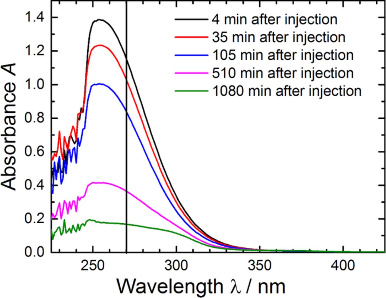
Figure 2. Absorbance of a solution of KO2 in DMSO after various periods of time after the injection of a 500-fold excess of Pyr14TFSI compared to the initial KO2 concentration. The vertical line at 270 nm corresponds to the wavelength used for the time vs. absorbance plot in Figure 1.
In a refined analysis which considers this spectral artefact, only the data points in Figure 1a corresponding to the consumption of ≤ 15% of the initial O• −2 concentration (marked by the dashed line) were considered for the determination of the pseudo-first-order reaction rate constant k'. We chose 15% as a compromise between having enough data points and avoiding the spectral interference from the decomposition products. This value was motivated by the fact that it just cuts off the last data points of the measurement with 10-fold excess of the ionic liquid. The first data point prior to the addition of the ionic liquid was also excluded in an effort to limit the error introduced during addition of Pyr14TFSI (i.e., the uncertainty in determining time = 0 due to mixing). The k'/c(IL)0 values obtained with this approach and listed in Table I are now reasonably close to each other, supporting the hypothesized second-order reaction between Pyr14TFSI and O• −2. The slightly higher k'/c(IL)0 value for an only 10-fold molar excess might be explained by the fact that the excess of Pyr14TFSI is not high enough to fulfill the assumed invariance of the Pyr14TFSI concentration over the course of the reaction, which was assumed in our pseudo-first-order reaction analysis. Unfortunately, it is not possible to fit the data as second-order reaction because the starting concentration of the superoxide radical solution would be needed. This concentration is slightly fluctuating with a standard deviation of 5% due to varying water content in the DMSO and the weighing error. Thus a background correction of the DMSO/KO2 baseline would be not possible as no normalization can be done as in case of a pseudo-first-order reaction. Finally, the slightly lower k'/c(IL)0 values at high molar excess assuming a pseudo-first-order reaction can be rationalized by considering the possible appearance of side reactions between O• −2 and intermediates arising from the decomposition of Pyr14TFSI.
Beyond these minor deviations, our results provide unambiguous proof of the reaction of O• −2 with Pyr14TFSI rather than the reaction of O• −2 with the minor impurities in the Pyr14TFSI, since an apparent second-order reaction rate constant of k'/c(IL)0 ≈ (4 ± 1)·10−3 l mol−1 min−1 was determined by varying the molar ratio of Pyr14TFSI/KO2 over a factor of 50. The comparison of this value of k'/c(IL)0 with the value obtained earlier by RRDE voltammetry23 confirms the better suitability of this UV-Vis method to quantify the long term stability of a given solvent against superoxide radical. More precisely, the RRDE-method only allowed us to estimate that k' would have to be smaller than 3·10−3 s−1; considering that these RRDE-measurements were performed in pure ionic liquid, this value transforms into k'/c(IL)0 = 56·10−3 l mol−1 min−1, one order of magnitude larger than the value estimated by UV-vis spectroscopy. Even though both model methods employ different superoxide radical sources and involve different counter-cations that may affect the intrinsic reactivity of superoxide, their results are qualitatively consistent. The question then arises whether such a slow reaction of the ionic liquid toward superoxide radicals has a significant impact on cell cycling, especially since two Li-O2 cell cycling studies with contradicting conclusions have been published very recently.37,42 Although a reaction rate constant in the order of 10−3 l mol−1 min−1 represents a rather slow reaction, we believe that the decomposition of the ionic liquid will nevertheless negatively impact cycle-life and ultimately lead to cell failure. It is in particular noteworthy to compare this rate constant to the upper-limit values for glymes and DMSO, which are in the order of 10−5 min−1 for an solvent excess of 50 as was reported in our earlier study.21 This value is more than one order of magnitude below that of Pyr14TFSI. Nevertheless, even glymes43 and DMSO44 are believed to react to a certain extent with superoxide, leading to cell failure, which suggests that the much higher reactivity of superoxide with Pyr14TFSI should have a much stronger impact. That Li-O2 cells employing Pyr14TFSI-based electrolytes suffer from very limited cycle life was indeed confirmed by our recent cell-cycling study.37
After having provided substantial proof that Pyr14TFSI does react with O• −2, it is important to understand the reaction pathways in order to guide the design of more stable ionic liquids. It would be most straightforward to analyze the solutions after the UV-Vis experiments, but unfortunately, the initial O• −2 concentration of only 3 mM results in decomposition product concentrations that are too low for an unambiguous detection by NMR. Since stirring of KO2 in the ionic liquid over an extended time did also not produce sufficiently high decomposition product concentrations, probably due to a very low solubility of KO2 in Pyr14TFSI, we sought for alternative ways to introduce high concentrations of O• −2 into Pyr14TFSI. The option we have pursued here is the in-situ generation of O• −2 in Pyr14TFSI by contacting lithiated LTO with O2, taking advantage of the reaction between these components recently described by Piana et al.37 Prior to describing these experiments, though, we will more closely examine the reaction between lithium titanate and oxygen using rotating ring disc electrode voltammetry.
Understanding the reactivity of O2 with lithiated LTO using RRDE voltammetry
Our group has recently proposed37 that the contact between lithiated LTO (Li4+xTi5O12, with 0 < x ≤ 3) and O2 solubilized in an aprotic solvent should result in the reduction of O2 to O• −2 and the oxidation of the LTO according to the following reaction:
![Equation ([8])](https://content.cld.iop.org/journals/1945-7111/162/6/A905/revision1/jes_162_6_A905eqn8.jpg)
This reaction is driven by the thermodynamically favorable potential difference between Li4+xTi5O12 (0 < x ≤ 3), with a redox potential of ≈1.5 VLi, and O2/Li2O2, with a thermodynamic potential E0 of 2.96 VLi. Moreover, in the presence of Li+, the O• −2 resulting from reaction 8 forms a short-lived lithium superoxide (LiO2) intermediate that can be further reduced and/or promptly disproportionate to Li2O2, as described in reactions 2–4. On the other hand, when Li+ is substituted with large cations45,46 such as the Pyr+14 in the ionic liquid used in this study, O• −2 can remain solvated, so that its reactivity with a given electrolyte can be studied using cyclic47 or rotating ring disc electrode23 voltammetry. The additional possibility of selectively detecting O• −2 at the electrode's ring renders this last technique a useful tool to verify the hypothesized production of superoxide radical upon contact between O2 and lithiated LTO. More precisely, the measurement presented below involves the sudden exposure to O2 of an RRDE with its disc loaded with lithiated LTO and immersed in Li+-free Pyr14TFSI. In this electrolyte, the titanate's OCV (≈1.5 VLi) remains sufficiently low to trigger the spontaneous reduction of O2 (electrochemically observed at <2.06 VLi),23 so that the resulting O• −2 would diffuse and get oxidized at the RRDE's ring, which would confirm the hypothesized mechanism formulated in reaction 8.
Practically speaking, the use of this approach requires the prior determination of the minimum ring potential at which the oxidation of O• −2 is under diffusion control (Ering,diff). In our previous study,23 this potential was estimated by recording polarization curves at a given scan rate and electrode rotation speed (5 - 50 mV s−1 and 2100 rpm, respectively) while holding the ring at different potentials. Using this configuration, an Ering,diff ≥ 2.71 VLi was estimated based on the identical ring currents recorded at potentials some 100 mV positive and negative of this value (i.e., at 2.81 and 2.61 VLi). Alternatively, Ering,diff can also be estimated by holding the disc at a potential at which the reduction of O2 is under diffusion control while scanning the ring potential between two boundary values at a given rotation rate. Following this procedure, Figure 3a features the ring currents recorded at various electrode rotation rates at a scan rate of 20 mV s−1 and in a potential range of 1.3 - 2.8 VLi, holding the disc electrode at a potential of 1.4 VLi at which the reduction of O2 to O• −2 is diffusion-controlled.22 The ring polarization curves feature reduction and oxidation currents at potentials below and above ≈2 VLi, respectively, which correspond to the reduction of the O2 in the electrolyte to O• −2 and the complementary oxidation of O• −2 produced at the disc. Assuming that these O2 reduction and O• −2 oxidation reactions are first-order with respect to the reactants' concentrations, the currents measured at any given potential (imeas,E) can be related to the corresponding diffusion-limited and kinetic currents (ilim and ikin,E respectively) using the Koutecky-Levich equation:
![Equation ([9])](https://content.cld.iop.org/journals/1945-7111/162/6/A905/revision1/jes_162_6_A905eqn9.jpg)
whereby ikin,E corresponds to the current that one would measure if the reactant concentration on the surface of the electrode were to be equal to that in the bulk of the electrolyte, ω is the electrode rotation speed, and B is a constant set by the electrolyte kinematic viscosity, the reactant's diffusivity and concentration, and the RRDE's geometry. Figure 3 indeed validates the linear relation between the 1/imeas-values versus 1/ω½ at ring potentials of 1.4 or 2.7 VLi. Moreover, the intercepts of the two lines at the origin of the axes (whereby 1/ikin,E = 0, or ikin,E → ∞) indicate that the O2-reduction and O• −2-oxidation ring currents at 1.4 or 2.7 VLi, respectively, are truly diffusion-limited. Thus, since the O• −2-oxidation currents at different ω's reach constant plateaus at ≥2.4 VLi, the ring potential of 2.7 VLi used in our previous work23 and in all RRDE measurements presented hereafter is more than sufficient to grant the diffusion-controlled collection of superoxide radical at the electrode's ring.
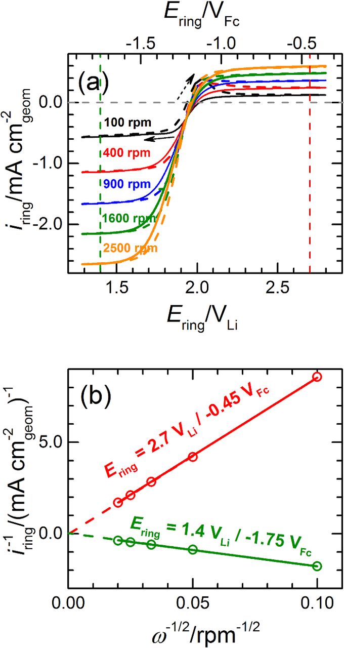
Figure 3. (a) Capacitively-corrected, but non-ohmically corrected polarization curves recorded in O2-saturated Pyr14TFSI at 25°C on an RRDE gold ring scanned at 20 mV s−1 and various electrode rotation rates while holding the glassy carbon disc at a potential of 1.4 VLi at which the reduction of O2 is under diffusion control.23 (b) Levich−Koutecky plots derived from the ring polarization curves in panel (a), at ring potentials of 1.4 or 2.7 VLi. Potentials are referenced either to Li/Li+ or to Fc+/Fc (cf. Experimental).
Having verified that Ering,diff ≥ 2.4 VLi, we move on to the LTO vs. O2-reaction-mechanism measurements, for which the RRDE's glassy carbon disc was loaded with ≈200 μg cm− 2disc of unlithiated LTO. Prior to the actual RRDE experiment, the LTO was galvanostatically lithiated at 87.5 mA g− 1LTO (equivalent to a C-rate of C/2) in Pyr14TFSI with 0.2 M LiTFSI, whereby the Li+-insertion charge accounted for ≈130 mAh g− 1LTO (or ≈18 mC, cf. Figure 4). This capacity is ≈75% of the material's theoretical value of 175 mAh g− 1LTO, and ≈20% less than the ≈165 mAh g− 1LTO obtained at the same discharge rate on a different commercial LTO with similar particle size and morphology (i.e., micrometer-sized, spherical LTO particles).48 This lower capacity in the RRDE configuration is most likely due to the absence of a conductive carbon additive in the electrode formulation. Practically speaking, though, the obtained Li+-insertion capacity is more than sufficient for our purposes.
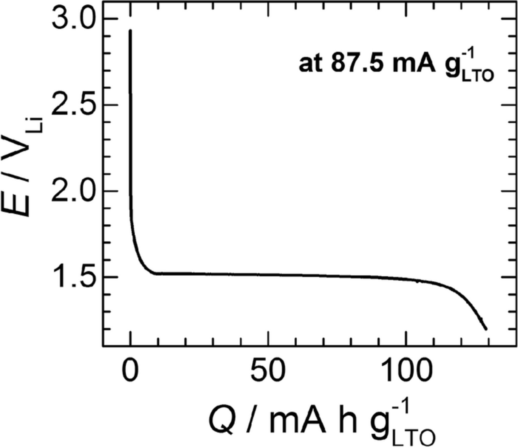
Figure 4. Li+-insertion profile upon galvanostatic lithiation (at 87.5 mA g− 1LTO, or C/2) of a glassy-carbon RRDE-disc loaded with ≈200 μgLTO cm− 2disc. The RRDE was mounted in a three-necked glass cell placed in an Ar-filled glovebox and filled with Pyr14TFSI with 0.2 M LiTFSI, using two pieces of Li foil as the counter and reference electrodes.
Following this lithiation step, the RRDE was rinsed inside the glovebox with fresh ionic liquid and mounted onto a different three-electrode cell filled with Li+-free Pyr14TFSI, which was then transferred outside of the glovebox and promptly connected to an Ar line to prevent air intrusion. The RRDE was then rotated at 400 rpm, keeping the disc at the OCV while holding the ring at the O• −2 detection potential of 2.7 VLi and recording its current response. Figure 5 displays the time evolution of these variables prior to and following the bubbling of O2 into the electrolyte. In the initially Ar saturated solution, the disc's OCV (cf. Figure 5) remained at a constant value of ≈1.4 VLi, corresponding to the fully lithiated LTO potential (cf. Figure 4). The subsequent addition of O2 caused the increase of this open circuit, which reached a value of ≈2.4 VLi after ≈10 min of O2-bubbling. This OCV-increase may be indicative of the delithiation (oxidation) of the Li7Ti5O12 to Li4Ti5O12 at open circuit in the presence of gaseous oxygen, consistent with equation 8, and/or of the formation of superoxide radical and Li2O2 discussed in the following. Most importantly, the corresponding ring current also experienced a sudden increase upon O2 dosing and then returning back to a quasi-zero baseline value after approximately 5 min, indicating the temporary release of O• −2 during Li7Ti5O12 delithiation, again consistent with equation 8.
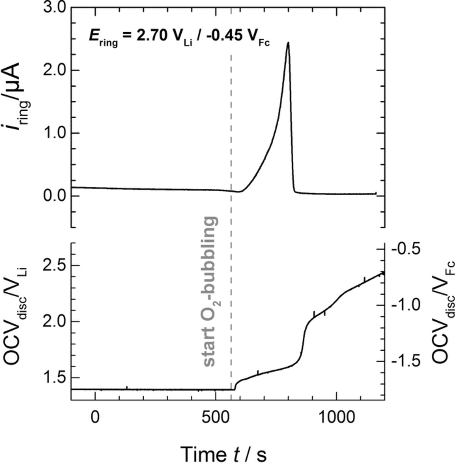
Figure 5. Time evolution of the open-circuit voltage (OCV) of the LTO-loaded disc (≈200 μgLTO cm− 2disc) and corresponding ring current (Ering = 2.7 VLi) in initially Ar-saturated Pyr14TFSI, whereby the gray dashed line indicates the moment in which O2 bubbling was started. The RRDE was constantly rotated at 400 rpm. Potentials are referenced either to Li/Li+ or to Fc+/Fc (cf. Experimental).
While this ring current transient qualitatively confirms the production of O• −2 upon contact between O2 and lithiated LTO according to equation 8, the integration of the area under its peak yields a charge of only ≈0.18 mC which, at a collection efficiency of 23 ± 2% determined in previous experiments with the same RRDE,23,40 corresponds to an O• −2 charge of ≈0.78 mC. This only amounts to ≈4.3% of the ≈18 mC of O• −2-formation charge expected on the basis of the Li+-insertion capacity in Figure 4 and assuming the 1:1 Li+:O• −2 reaction pathway formulated in equation 8 for complete delithiation (y = 3). This discrepancy points toward side-reactions that consume a significant fraction of the superoxide radical diffusing from disc to ring. One possibility is the reaction of formed O• −2 with the released Li+ ion to LiO2 (cf. equation 2), which can further disproportionate or get reduced to solid Li2O2 (cf. equations 3 and 4) that would remain on the LTO surface and would not be detected at the ring. To verify this possibility, the measurement in Figure 5 was followed by the re-saturation of the electrolyte with argon for 30 min, while holding the LTO-loaded disc at a potential of 2.5 VLi at which no further O2-reduction takes place.23 Figure 6 shows the CVs subsequently recorded on the disc from 2.5 VLi to 4.5 VLi, which should allow for the oxidation of the Li2O2 without compromising the stability of the electrolyte.49 Interestingly, the first positive-going scan displays an oxidation current remarkably larger than that observed in the subsequent, steady-state CV, therefore confirming that some Li2O2 was formed during LTO delitiation under O2. However, following the subtraction of the double-layer capacity in the steady state CV from the charge in the first positive-going scan and its integration, the Li2O2-oxidation charge was only ≈0.16 mC, which again only accounts for a minor fraction (≈1%) of the titanate's initial 18 mC.
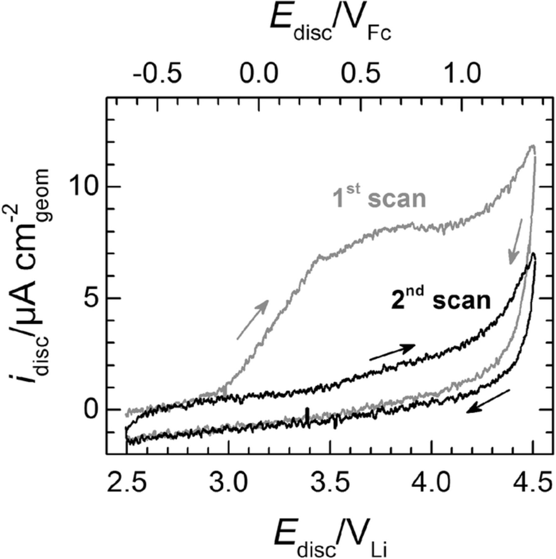
Figure 6. Cyclic voltammograms in Ar-saturated Pyr14TFSI at 25°C, recorded at 10 mV s−1 and 400 rpm on the RRDE-disc loaded with ≈200 μgLTO cm− 2disc just after the reaction of lithiated LTO with O2 at OCV shown in Figure 5. The gray line corresponds to the initial scan from 2.5 and 4.5 VLi, whereas the black line corresponds to the subsequent second (and steady state) voltammogram within the same potential window. The arrows indicate the scanning direction.
Alternatively, the low O• −2 yield of ≈4.3% in Figure 5 may arise from a chemical reaction between superoxide and the ionic liquid, even though this would seem to contradict our previous observations,23 whereby Pyr14TFSI was stable vs. O• −2 on a time-scale on the order of 10 seconds, which is not so different from the exposure time-scale on the order of 100 seconds (cf. Figure 5). It may be the case, however, that the local O• −2 concentration near the LTO surface is much higher than that produced during the O2 reduction on the RRDE disc electrode in our previous study, so that the reaction rate between O• −2 and Pyr14TFSI could be higher. Another option is that unlike in our previous study, the RRDE measurements presented here contain Li+ ions from the delithiation of the LTO, which may result in LiO2 formation. This LiO2 may have disproportionated into Li2O2 within its transient to the ring (accounting for a reaction time of ≈4.5 seconds at the 400 rpm used herein, cf. Ref. 23). Additionally, while we are not aware of any studies dealing with the effect of counter-cations on the reactivity of O• −2 with the surrounding electrolyte, the solvation of superoxide by small cations (i.e., hard Lewis acids) like Li+ or Na+ has been reported to result in a more unstable intermediate than when the solvation agents consist of larger cations (i.e., soft Lewis acids) like tetrabutylammonium or the Pyr+14 used herein.50 This combination of a moderately soft Lewis base (O• −2) and a hard Lewis acid (Li+) leads to a weakly bound complex whereby the superoxide remains highly electronegative, possibly increasing its reactivity toward the ionic liquid. Nevertheless, this explanation remains highly tentative, and further efforts should be devoted to clarifying the cause(s) for the unexpectedly low O• −2 and Li2O2 yields.
In summary, our RRDE measurements have provided qualitative confirmation of the reaction mechanism between O2 and lithiated LTO, namely the delithiation of the titanate and the reduction of O2 to yield O• −2 according to equation 8. The low amount of O• −2 collected at the ring electrode points toward side reactions other than the formation of Li2O2 and that may result from the formation of a highly-reactive LiO2 intermediate.
Decomposition products of Pyr14TFSI from the reaction with O• −2 generated from lithiated LTO and O2
Since considerably less superoxide was collected at the ring of the RRDE than stoichiometrically expected from the delithiation reaction of lithiated LTO with O2 (cf. equation 8), we prepared LTO electrodes with a very high loading to ensure sufficient concentration of superoxide to detect Pyr14TFSI degradation products by NMR. While for the RRDE experiment ≈40 μg of LTO were used in combination with ≈20 ml of electrolyte (i.e., 2 μgLTO ml− 1IL), the degradation of Pyr14TFSI was studied with electrodes containing 400 mg LTO and contacted with 400 μl of ionic liquid (i.e., 106 μgLTO ml− 1IL). Assuming that similar to the RRDE experiment at least ≈4.3% of the charge of the fully lithiated, high loading LTO electrodes will be converted to O• −2, the expected O• −2 concentration generated in the Pyr14TFSI would be ≈0.3 mol l−1. This is two orders of magnitude larger than the KO2 concentration used in the UV-Vis experiments (3 mmol l−1), while the Pyr14TFSI would still be in molar excess compared to O• −2 (≈10:1). In reality, the local O• −2 concentration might even be larger (cf. above discussion). Owing to the roughly 10- and 100-fold higher concentrations of Pyr14TFSI and O• −2, respectively, which should increase the Pyr14TFSI decomposition rate by roughly three orders of magnitude (cf. equation 5) in combination with the fact that no other solvent is used which would dilute the decomposition products (as is the case in the above UV-Vis experiment), the concentration of the Pyr14TFSI degradation products should easily be high enough for detection by NMR. However, one has to keep in mind that for a 1:1 stoichiometry of the reaction of O• −2 with Pyr14TFSI, at most 10% of the ionic liquid could decompose.
Allowing 1 hour of reaction time between the lithiated LTO electrode, O2 and, Pyr14TFSI did not result in any detectable decomposition products by NMR, in contrast to the quasi-immediate detection of superoxide at the RRDE-ring (cf. Figure 5). As pointed out before, though, the LTO electrode employed in these tests is considerably thicker (≈1 mm) than the one coated on the disc electrode (≈1–2 μm) resulting thus in limited O2 and O• −2 transport toward and away from the lithiated LTO particles, which might delay the reaction substantially. Furthermore, it was shown by UV-Vis spectroscopy that the reaction of superoxide with Pyr14TFSI is relatively slow (cf. Figure 1). Therefore, we prolonged the reaction time to 6 h and 24 h, which led indeed to detectable decomposition products in the 1H NMR spectra shown in Figure 7, noticeable also by a fishy amine smell during Ar flushing.
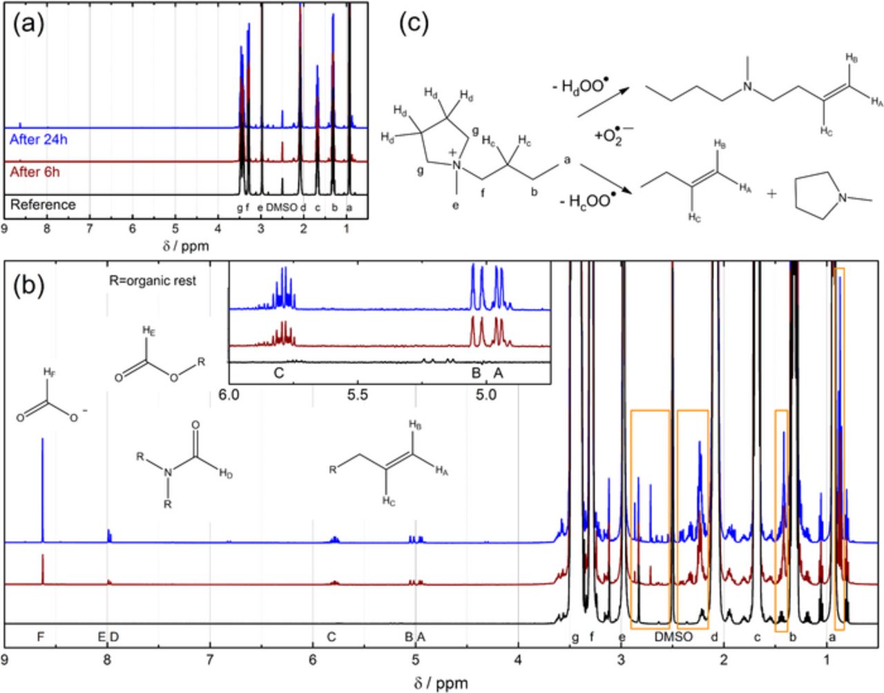
Figure 7. (a) 1H NMR analysis (500.36 MHz, referenced to the solvent DMSO-d6) of pure Pyr14TFSI (black line) and of Pyr14TFSI after 6 h (brown line) and 24 h (blue line) of contact with lithiated LTO and O2. (b) Zoom of (a) including fragments of detected decomposition products. Areas showing signals of decomposition products within the range of the chemical shift of Pyr+14 are highlighted by orange boxes. The inset shows the area between 4.75 and 6.0 ppm further magnified. (c) Scheme of the Hofmann β-H elimination reaction caused by the reduction products of O2. The NMR signals in (a) and (b) of the protons of Pyr+14 and the decomposition products are labelled with small and capital letters as assigned in the structural formula.
All 1H NMR signals of the Pyr+14 cation have a chemical shift lower than 3.5 ppm, so that signals of decomposition products with a higher shift can be studied and integrated most easily. As can be seen in Table II, the strongest signal consists of a singlet at 8.63 ppm, which can be attributed to formate, while substantially weaker singlets at 7.99 and 7.97 ppm may belong to some formate esters and/or formamides. The multiplet centered at 5.8 ppm and the two doublets around 5.0 ppm can be clearly assigned to protons on a terminal C-C double bond, thanks to multiplicity and coupling constants (JC,allylic = 6.6 Hz, JAC = 10.2 Hz, JBC = 17.1 Hz). This assignment is consistent with our previous work,37 in which we described the same products in the electrolyte of a cycled Li-O2 cell. Similar decomposition products were also detected by others studying the electrochemical reduction of the Pyr+14-cation.4,5 As neither a negative potential is applied nor contact with lithium metal is made in this study, only the ORR intermediates formed due to the delithiation of LTO can cause the detected decomposition, whereby superoxide radicals react mainly via nucleophilic attack51 and deprotonation.52 While it is widely accepted nowadays that carbonate electrolytes decompose in Li-O2 cells via nucleophilic attack of superoxide,51 quaternary ammonium cations such as piperidinium or pyrrolidinium, in contrast to imidazolium cations, were judged to be resistant to nucleophiles due to equally distributed negative Mulliken charges.25 Since the 19th century, however, it has been known that quaternary ammonium salts decompose in presence of hydroxide by Hofmann β-H elimination.53 Although a pKa of 4.7 of the corresponding acid hydroperoxy radical HOO• suggests that O• −2 has a basic strength comparable to acetate, O• −2 can deprotonate very weak acids with a pKa ≈ 25, as its apparent basicity is substantially higher due to a subsequent electron transfer reaction.54 Therefore, the hydrogen atoms of the carbon at the β-position of quaternary ammonium cations could be easily eliminated by superoxide as shown in Figure 7c, which was confirmed by the olefins detected by NMR. Interestingly, we indeed found evidence for two different compounds with terminal double bonds, as next to the described multiplet and doublets, signals with lower intensity but identical multiplicity and coupling pattern were observed (cf. inset Figure 7b). Unfortunately, determining by NMR whether the Hc or Hd protons of Pyr+14 (cf. Figure 7c) are more likely eliminated is difficult and is further complicated by the fact that the gaseous product butene might vanish in substantial amounts by the flushing with argon prior to cell disassembly and sampling for NMR analysis. The so-called "Hofmann rule" states that β-H are eliminated with preference from CH3 > CH2 > CH, which would suggest that, for example, Pyr+12 would be more prone to deprotonation than Pyr+14.3 Furthermore, it was found through DFT calculations that the longer the aliphatic chain on the nitrogen, the more difficult the β-H elimination.55
Table II. Integrals of protons of the decomposition products of Pyr14TFSI after 6 h and after 24 h of reaction with ORR intermediates generated from lithiated LTO in contact with O2. The integrals are normalized to the integral of the protons at the methyl chain (proton e, cf. Figure 7) of Pyr14TFSI which is set to 100 for 1 proton.
| Compound | Label | δ(1H NMR)/ppm | Integral after 6 h | Integral after 24 h |
|---|---|---|---|---|
| Olefin | A | 4.95/4.92 (d, 1H) | 0.35 | 0.53 |
| Olefin | B | 5.04/4.99 (d, 1H) | 0.34 | 0.51 |
| Olefin | C | 5.79/5.86 (ddt, 1H) | 0.34 | 0.51 |
| Formamide | D | 7.97 (s, 1H) | 0.06 | 0.18 |
| Formate ester | E | 7.99 (s, 1H) | 0.10 | 0.31 |
| Formate | F | 8.63 (s, 1H) | 0.43 | 1.27 |
Even though such rules provide some hints how a Hofmann elimination reaction might be prevented, the safest rule is the complete avoidance of any β-H. Moreover, the methyl group can also be removed in a SN2 reaction, which is, however, less favorable.55 The final product of this SN2 reaction would be methanol, which could not be detected by NMR in this study due to the overlap with the Hg of pyrrolidinium. Yet, it was possible to distinguish signals of decomposition products with a chemical shift similar to the pyrrolidinium cation, which are highlighted by the orange boxes in Figure 7b, even though they could not be reasonably integrated due to their overlap with the Pyr+14 signals and satellites. Aliphatic signals (0.87 ppm, t and 1.42 ppm, m) and signals that can be assigned to protons in the vicinity of N and to allylic protons (2.2–2.4 ppm, m) confirm the above-described Hofmann elimination. The singlets at 2.71 ppm and 2.86 ppm may belong to formamides or esters and may be related to the singlets at 7.99 and 7.97 ppm. Since these singlets as well as the formate singlet increase much more with reaction time (from 6 h to 24 h) than the olefinic signals (Table II), we believe that they are the products of consecutive reactions. According to Frimer et al., superoxide does not react with non-activated double bonds.56 The corresponding acid HOO• reacts, however, with another superoxide to produce HOO− or may also abstract an allylic hydrogen atom leading to autooxidation,57 so that several consecutive reactions can be imagined leading finally to the detected oxidized products. While the initially formed olefins may not be problematic with regards to Li-O2 cell cycle-life due to their solubility in the electrolyte, accumulation of salts such as formates will result in precipitation and finally block the electronically-conducting electrode support material, thus preventing further Li2O2 formation and leading to cell failure.
The decomposition products found by 1H NMR relate the pseudo-first-order reaction observed by the UV-Vis screening method (cf. Figure 1) to the decomposition of the Pyr14 cation. But since recently fluorine containing degradation products were found by 19F NMR in the D2O extracts of discharged Li-O2 cathodes with LiTFSI based electrolytes,58,59 it is important to verify whether TFSI− decomposition also plays a major role in the degradation of the ionic liquid Pyr14TFSI. Figure 8 presents the 19F NMR spectra of the ionic liquid after 6 h and 24 h of contact with the lithiated LTO electrode and O2. After both reaction times, only a tiny singlet at −75.6 ppm was detected, which was assigned to a CF3-containing degradation fragment in agreement with a similar signal observed by Nasybulin et al.59 In contrast, no signal around −125 ppm related to LiF was detected. This consecutive decomposition product may be completely insoluble in the ionic liquid and thus not detectable in the reaction solution. Integration of the signal at −75.6 ppm of the more soluble CF3-containing degradation fragment and normalization to the 6 protons of the TFSI singlet reveals, however, that the transformation of TFSI− into this CF3-containing degradation fragment after 6 and 24 h was less than 0.005 and 0.01%, respectively. This amount is negligible when compared to the roughly 2.5% of degradation products observed by 1H NMR after 24 h reaction time, estimated by considering only the products with a high chemical shift listed in Table II. This clearly points to the Pyr14 cation as the main source for the O• −2 instability of Pyr14TFSI.
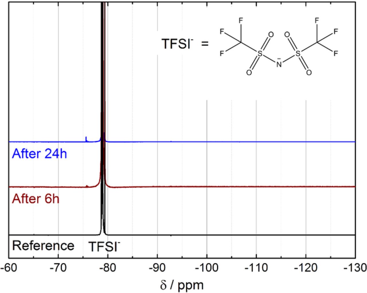
Figure 8. 19F NMR analysis (470.78 MHz, DMSO-d6) of pure Pyr14TFSI as reference and of Pyr14TFSI after 6 h (brown line) and 24 h (blue line) contact with lithiated LTO and O2.
Conclusions
We conclude that the ionic liquid Pyr14TFSI is subject to degradation by superoxide radicals even though it has frequently been considered to be a stable alternative for Li-O2 cell solvents. With our recently developed KO2 screening method, we successfully determined the apparent second-order reaction rate constant of Pyr14TFSI with superoxide radical to ≈(4±1)·10−3 l mol−1 min−1. Taking advantage of the reaction between lithiated LTO upon contact with O2 to generate superoxide radicals, first proposed in our previous study37 and proven herein by RRDE-voltammetry, we developed a new method to detect soluble degradation products from the reaction of Pyr14TFSI with superoxide radicals. With this method, we showed that superoxide radicals deprotonate the β-carbon of the quaternary ammonium cation, which subsequently leads to the degradation of the Pyr14 cation. Thus, ammonium-based ionic liquids with β-H are not expected to be stable in Li-O2 cells. On the other hand, we found that the degradation of the TFSI anion is rather minor compared to the Pyr14 cation.
Furthermore, care should be also taken when using Pyr14TFSI in Li-ion batteries, since water introduced by leaks or produced during cycling might be reduced to OH−, which can also initiate the described Hofmann β-H elimination. That LTO is not a suitable anode material for Li-O2 cells is obvious from our previous publication37 and from the experiments here shown, but the fact that O2 delithiates LTO and produces reactive oxygen reduction intermediates may also have a negative impact on cycle and especially calendar life of Li-ion batteries, as O2 permeation through the cell housing will always occur over battery life.
Acknowledgments
We thank the BASF SE for financial support through the framework of its Scientific Network on Electrochemistry and Batteries, and in particular Arnd Garsuch for his coordinating role. The authors further acknowledge Dyneon GmbH (3M Advanced Materials Division) for kindly providing free samples of the non-stabilized PTFE dispersion. We thank Wolfgang Eisenreich and his team for their help with the NMR measurements. K.U.S. thanks the TUM Graduate School.