Abstract
The corrosion/passivation phenomenon of Al and stainless steel (SS) with an ionic liquid-based electrolyte N-methyl-N-propyl-piperidinium bis(fluorosulfonyl)imide (PMpipFSI)-LiFSI was systematically studied by cyclic voltammetry, and its impact on the battery performance was evaluated in NMC532/Li cell. Our results showed that these electrolytes could eliminate the Al corrosion due to their capability of forming a passivation layer during the first anodic scan after 3 V vs Li+/Li. In contrast, no passivation behavior was observed for SS electrode, and the corrosion reaction was kinetically suppressed when the lithium salt concentration increases. We demonstrated that while 1 M LiFSI-PMpipFSI extensively corrodes SS in a NMC532/Li cell, the 5 M electrolyte does not and actually enables the normal cycling of the cell both using SS-2032-coin cells. Further, when an Al-coated coin cells were used, the Coulombic efficiency dramatically improved from 90% to >99.9% with superior capacity retention at both room temperature and 55°C.
Export citation and abstract BibTeX RIS

This is an open access article distributed under the terms of the Creative Commons Attribution 4.0 License (CC BY, http://creativecommons.org/licenses/by/4.0/), which permits unrestricted reuse of the work in any medium, provided the original work is properly cited.
Lithium-ion battery (LIB) has been the main stream energy storage to power the modern consumer electronics and the electric vehicles (EVs) due to its many advantages over other battery chemistries.1–4 However, the energy density for the next-generation LIB needs to be increased in order to further extend the electric driving range with mitigated driving anxiety from the driver. Also, the enhanced safety of the LIB is required to ensure the reliability of the LIB as a daily commodity. To meet both requirements, a high-voltage and non-flammable electrolyte needs to be developed. Designed for the 4-V LIB chemistry, the state-of-the-art (SOA) carbonate-based electrolyte decomposes beyond 4.3 V vs Li+/Li, which could not support the redox reaction of high-voltage high-capacity cathode occurring at potentials >4.3 V.5–7 Also, it is highly flammable due to the presence of volatile organic carbonate solvents causing severe safety concern.2,8
Ionic liquid (IL) is considered as a promising alternative to the carbonate electrolytes due to its wide electrochemical window, nonflammability and extremely high thermal stability.9–15 IL-based electrolytes have been reported to be able to support the chemistries of lithium batteries, but ideally also have the potential to improve their performance, especially with respect to cycle stability at high voltages and high temperatures. Generally, the viscosity of the ILs is two to three orders magnitude higher than that of the SOA solvents, and becomes even higher when the lithium salt is present which limits its application in LIBs.16 Therefore, the sulfonyl imide anions based ILs are the most widely explored due to their relatively lower viscosity thanks to the electron-delocalized structure. Compared with bis(trifluoromethylsulfonyl)imide (TFSI−), the bis(fluorosulfonyl)imide (FSI−)-based ILs are less viscous due to the smaller size of F compared to CF3 group. For example, the N-methyl-N-propyl piperidinium-FSI (PMpipFSI) has a ambient viscosity of 95 mPa·s, and it increases to 151 mPa·s when the anion is switched to TFSI−.17 Another advantage of the FSI−-based ILs is the high compatibility with graphite anode due to its solid-electrolyte-interphase (SEI) formation capability.18
In contrast to LiPF6 based carbonate electrolytes which passivate Al by forming insoluble AlF3 and LiF,19–24 the amide salt including LiFSI and LiTFSI based carbonate electrolytes could not effectively passivate Al current collector on cathode, causing severe corrosion dissolution of Al. However, the results on passivation behavior for amide salt based IL electrolytes were controversial.25–29 Cho et al.28 reported that 1 M LiTFSI N-methyl-N-propyl pyrrolidinium-FSI corrodes Al current collector at potentials >4.0 V vs. Li+/Li tested by cyclic voltammetry using 2032-coin cells, and this corrosion could be suppressed by the addition of 0.1 M LiPF6 salt, while others demonstrated that both FSI- and TFSI-based IL electrolytes are corrosion free.30–32 Apparently, the lithium salt or anion structure, purity of lithium salt,33 and electrolyte solvent all impact the passivation/corrosion behavior of an electrolyte.
Lithium salt concentration also plays a significant role in suppressing the corrosion of Al current collector. Recently, Yamada et al. reported that the super concentrated acetonitrile-LiFSI showed exceptional voltage stability and corrosion free due to their unique solvation structure.34 Similar results were reported for the concentrated EC-LiTFSI electrolytes.35
In this paper, we report the corrosion/passivation behavior of an FSI-based IL electrolyte N-methyl-N-propyl piperidinium-FSI (PMpipFSI) dissolved with different LiFSI concentrations in different 2032-coin cell configurations, and how it impacts the electrochemical performance of NMC532/Li cells at room temperature and at elevated temperature (55°C).
Experimental
Materials
NMC532 cathode (LiNi0.5Mn0.3Co0.2O2; active material area loading 10.26 mg/cm2) laminates were supplied by the Cell Analysis, Modeling, and Prototyping (CAMP) Facility at Argonne National Laboratory. LFP cathode (LiFePO4) was prepared by mixing LiFePO4 (90%), C45 carbon black (5%), and PVDF binder (5%) in N-methyl-2-pyrrolidinone (NMP) and the resulting slurry was then cast onto Al foil (active material area loading: 10.79 mg/cm2). The electrode laminates were punched into 14 mm discs in diameter and dried at 120°C under vacuum for overnight. Li chips were purchased from MTI Corporation (15.6 mm in diameter and 0.2 mm in thickness).
Synthesis of PMpipFSI
PMpipFSI was synthesized by the ion exchange reaction of 1-methyl-1-propylpiperidinium bromide (IoLiTec Inc.) with LiFSI (Nippon ShokuBai Co., Ltd.). The ionic liquids were extracted with ethyl acetate and washed with de-ionized water until no residual halides were detected by saturated AgNO3 solution. ILs were dried on lyophilizer for at least 2 days, and then stored over 4 Å molecular sieves before use. The water content was measured to be < 30 ppm by Mettler Toledo coulometric Karl-Fischer titrator C30.
Viscosity and conductivity measurement
The viscosity was measured by ViscoLab 4000 at room temperature. Ionic conductivity (σ) was determined by electrochemical impedance spectroscopy (EIS) using Solartron Analytical 1400 Cell test working station. The distance between the two stainless steel electrodes (l) was fixed to 0.172 cm by using a Teflon ring spacer with the inner area (A) of 0.502 cm2. EIS was measured to obtain the ohmic resistance (RΩ) of the electrolyte sample from the Nyquist plot at the intersection with Z' axis at the high frequency. The ionic conductivity was then calculated by Equation 1.
![Equation ([1])](https://content.cld.iop.org/journals/1945-7111/166/16/A3959/revision1/d0001.gif)
Metal corrosion test
Cyclic voltammetry was performed using a Gamry Instrument potentiostat reference 600+. The measurements were carried out in a 2032-coin cells using Al (14 mm in diameter) or stainless-steel (SS) disc (15.6 mm in diameter) as working electrode, lithium as both counter and reference electrode (15.6 mm in diameter), and glass-fiber as the separator (16 mm in diameter). The scan rate was 10 mV/s.
Standard and Al-coated 2032-coin cell configurations are illustrated in Figure 1.36 In the standard cell configuration (Figure 1a), two SS spacers are included: one is between the cathode/working electrode and cathode cap, and the other one is between the anode/Li chip and spring/anode cap. In the Al-coated 2032-coin cell configuration (Figure 1b), both SS spacers are placed on the anode side (between anode/Li chip and spring) with cathode cap coated with aluminum.
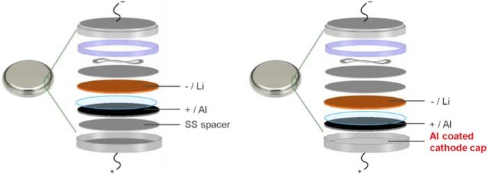
Figure 1. (a) Standard 2032-coin cell configuration used for cyclic voltammetry and cell cycling test and (b) Al-coated 2032-coin cell configuration with two SS spacers placed on anode side.
Li-ion cell cycling test
Galvanostatic charge-discharge cycling of LFP/Li and NMC532/Li cells were conducted with standard and Al-coated 2032-coin cells on Maccor (MIMSclient) cycler. The glass fiber separator GF/F (16 mm in diameter) was used and the total electrolyte amount is 100 μL for both Gen 2 and PMpipFSI electrolytes. The effective electrode area was 1.54 cm2 for LFP and NMC532 cathode. These cells were first formed with C/20 rate for 3 cycles followed by 100 cycles with C/10 rate. The cycling testing was conducted at 25°C and 55°C.
Results and Discussion
Electrochemical performance in standard 2032-coin cell
PMpipFSI based electrolyte with various LiFSI concentrations were prepared in an argon-filled glove box, and their physicochemical properties are summarized in Table I.
Table I. Summary of LiFSI-PMpipFSI Electrolyte Composition, Viscosity and Conductivity with Various Amounts of LiFSI Salt.
| Molar ratio of each ion | ||||||||
|---|---|---|---|---|---|---|---|---|
| Denoted concentr-ationa | Molarity of LiFSI (mol/L) | Molality of LiFSI (mol/kg) | Li+ | PMpip+ | FSI− | Viscosity (cP @ RT) | Conductivity (× 10−3 S/cm @ RT) | Conductivity (× 10−3 S/cm @ 50°C) |
| - | 0 | 0 | 0 | 0.50 | 0.50 | 87.25 | 3.50 | 9.09 |
| 1 M | 0.93 | 0.76 | 0.10 | 0.40 | 0.50 | 133.5 | 2.24 | 5.57 |
| 2 M | 1.7 | 1.5 | 0.16 | 0.34 | 0.50 | 249.0 | 1.25 | 4.05 |
| 3 M | 2.4 | 2.3 | 0.21 | 0.29 | 0.50 | 396.0 | 0.819 | 2.50 |
| 4 M | 2.9 | 3.0 | 0.25 | 0.25 | 0.50 | 601.3 | 0.555 | 2.05 |
| 5 M | 3.4 | 3.8 | 0.28 | 0.22 | 0.50 | 936.6 | 0.353 | 1.58 |
aDenoted concentration of LiFSI is determined by the X millimoles of LiFSI dissolved in 1 mL of PMpipFSI.
Figure 2a shows the cycling performance of 1 M LiFSI-PMpipFSI electrolyte in a LiFePO4/Li cell with a cutoff voltage of 3.8-3.0 V, which is the widely used cathode for IL-based electrolyte evaluation.37,38 The cell was tested in a standard 2032-coin cell setup (Figure 1a). Surprisingly, when a higher voltage NMC532/Li cell was used (cutoff voltage 4.3-3.0 V), a low initial capacity of 140.6 mAh/g was obtained and the capacity fades rapidly within first 30 cycles with only 80% Coulombic efficiency as shown in Figure 2b. Apparently, the poor cell performance was not caused by the electrode or the testing condition since the conventional Gen 2 electrolyte (1.2 M LiPF6 EC/EMC 3/7) cell cycles well as evidenced by the cycling data shown in Figure 2b. The inherent property of high voltage stability of IL-electrolytes excludes the possibility of oxidative decomposition at 4.3 V,17 indicating other side reactions occur at this voltage. Interestingly, when the LiFSI concentration increases, the cycling performance dramatically improved. Figure 2c showed the capacity retention and Coulombic efficiency for 2–5 M LiFSI-PMpipFSI cells. 4 M LiFSI is a threshold value since no obvious change in cell performance when salt concentration is further increased to 5 M, the maximum salt concentration. It is noticeable that although the increased salt concentration improves the cell performance, the cell capacity still degrades cycle by cycle and the Coulombic efficiency is still low (only 90–95%), indicating that a different underpinned mechanism dictates the observed electrochemical behavior, which leads us to investigate the corrosion/passivation behavior on the metals in the standard 2032-coin cell setup.
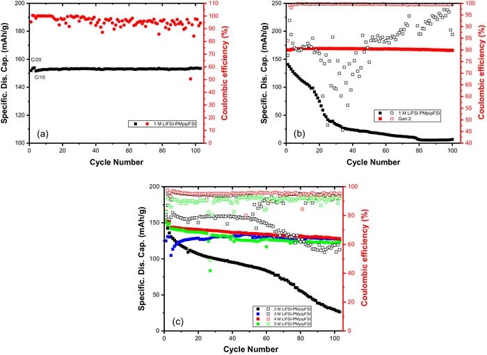
Figure 2. (a) Cycling performance of 1 M LiFSI-PMpipFSI electrolyte in LiFePO4/Li cell with a cutoff voltage of 3.8-3.0 V; Cycling performance of NMC532/Li cells with (b) 1 M LiFSI-PMpipFSI and Gen 2 electrolyte and (c) 2–5 M LiFSI-PMpipFSI electrolytes with a cutoff voltage of 4.3-3.0 V. (Temperature: 25°C, testing vehicle: standard 2032-coin cell).
Metal corrosion study by cyclic voltammetry
Cyclic voltammetry was conducted in the standard 2032-coin cell setup using Al foil as working electrode and Li chip as counter and reference electrode. Figure 3 shows the CV profiles of 1–5 M LiFSI-PMpipFSI and Gen 2 electrolytes. Gen 2 electrolyte shows the typical passivation behavior after the 1st anodic scan to 6.0 V and no corrosion was observed afterwards. However, all the IL-electrolytes exhibits different degree of pitting corrosion39–41 during the 1st anodic scan (Figure 3a), and this behavior continues in the following scans (Figure 3b) indicating these electrolytes could not passivate the metal. Another important observation is that the corrosion current density decreases with increased LiFSI salt concentration, suggesting the highly concentrated PMpipFSI electrolyte could kinetically suppress the corrosion to a certain degree that could support the normal redox reactions on the cathode at 4.3 V. The CV data correlate well with the improved cycling of 5 M LiFSI PMpipFSI electrolyte in NMC532/Li cell reported in Figure 2c. Cho et al. reported the same cyclic voltammetry of 1 M LiTFSI in 1-methyl-1-propylpyrrolidinium bis(fluorosulfonyl)imide (PMpyrFSI) ascribing to the Al corrosion issue.28
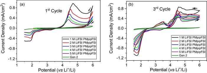
Figure 3. Cyclic voltammograms of PMpipFSI with 1–5 M LiFSI salt concentration and Gen 2 electrolyte. (a) 1st cycle, and (b) 3rd cycle. (Working electrode: Al, counter and reference electrode: Li, coin cell setup: standard 2032-coin cell case, scan rate: 10 mV/s.).
However, there are two possible corrosion sources in this standard 2032-coin cell setup: Al and SS.42–45 To isolate these two corrosion sources, an Al-coated 2032-coin cell setup was employed for cyclic voltammetry study. As shown in Figure 1b, the internal side of the cathode cap (made of SS) is coated with Al and the SS spacer placed between the cathode cap and the cathode/working electrode was moved to the anode side in order to evaluate the Al corrosion/passivation behavior. Figure 4 summarize the cyclic voltammograms of 1 M, 5 M LiFSI-PMpipFSI and Gen 2 electrolyte, respectively. For 1 M and 5 M PMpipFSI electrolytes, the Al oxidation starts at 3.2 V and 3.5 V in the first anodic scan and the corrosion current density is 50 times smaller than that obtained in the standard 2032-coin cell setup shown in Figure 3a (Al working electrode with an adjacent SS spacer). Different from the results tested in standard 2032-coin cell setup, no corrosion reaction was observed at the 2nd and 3rd scan, indicating both 1 M and 5 M electrolyte could effectively passivate the Al and thus inhibit its corrosion. As expected, Gen 2 electrolyte showed the passivation behavior on Al as evidenced from the CV data in Figure 4c. At this point, it is evident that both low and high concentration PMpipFSI electrolytes could effectively passivate the Al, and the large corrosion current observed in the standard 2032-coin cell setup were originated from the corrosion of SS spacer used in the cell.
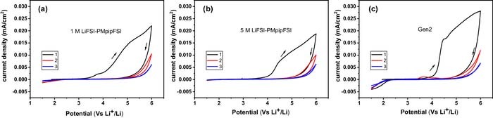
Figure 4. Cyclic voltammograms of (a) 1 M LiFSI-PMpipFSI, (b) 5 M LiFSI-PMpipFSI and (c) Gen 2 electrolyte using Al working electrode in a Al-coated 2032-coin cell setup. (Working electrode: Al, counter and reference electrode: Li, scan rate: 10 mV/s).
To further confirm it, cyclic voltammetry analysis using SS as working electrode in standard 2032-coin cell setup was carried out. Cyclic voltammograms for the 1st and 3rd cycles are provided in Figure 5. As expected, Gen 2 electrolyte is capable of passivating SS and inhibits corrosion in the subsequent cycles, while all the PMpipFSI electrolytes showed strong corrosion currents. The corrosion current density is 3 times larger than that shown in Figures 3a–3b when Al working electrode was used in the standard coin cell setup. Similar results as shown in Figure 2c, when the LiFSI concentration increases from 1 M to 4 M and 5 M, the SS corrosion is mitigated to a degree that the electrolyte enables the regular cycling of NMC532 cathode at 4.3 V. In conclusion, these cyclic voltammetry studies indicate: (1) the LiFSI-PMpipFSI IL electrolytes could well passivate Al current collector, but corrodes the SS, and (2) the highly concentrated PMpipFSI electrolytes could kinetically suppress the stainless-steel corrosion reaction to a low degree that it could support the normal redox reaction of NMC cathode.
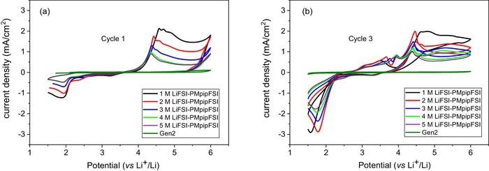
Figure 5. Cyclic voltammograms of 1–5 M LiFSI-PMpipFSI and Gen 2 electrolyte. (a) 1st cycle, and (b) 3rd cycle. (Working electrode: stainless steel spacer, counter and reference electrode: Li, coin cell setup: standard 2032-coin cell case, scan rate: 10 mV/s).
Electrochemical performance in Al-coated 2032-coin cell
The cyclic voltammetry study elucidates the corrosion behavior of the PMpipFSI based electrolyte on Al and SS. We re-evaluated the electrochemical performance of PMpipFSI electrolytes in NMC532/Li cells using a revised 2032-coin cell setup (illustrated in Figure 1b where an Al-coated cathode cap without a SS spacer was used on the cathode side). Figure 6a showed the specific discharge capacity and Coulombic efficiency of 1 M and 5 M LiFSI-PMpipFSI electrolytes. Both electrolytes showed excellent cycling stability. Specifically, 1 M electrolyte cell delivers an initial capacity of 152 mAh/g and 149 mAh/g at 100 cycles. For 5 M cell, it delivers a lower capacity of 139 mAh/g due to its high viscosity (Table I). The capacity retention is superior for this electrolyte (a higher capacity of 147 mAh/g at 103 cycle is due to slow electrode wetting). Compared with only 90% obtained in the standard 2032-coin cells, the average Coulombic efficiency for the Al-coated cells is 98.9% and 99.8% for 1 M and 5 M LiFSI-PMpipFSI, respectively.
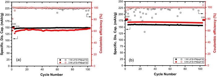
Figure 6. Cycling performance of 1 M and 5 M LiFSI-PMpipFSI in NMC532/Li cells (a) at room temperature and (b) at 55°C. (Cutoff voltage: 4.3-3.0 V; temperature: 55°C; testing vehicle: Al-coated 2032-coin cell.)
To evaluate the stability of the Al passivation layer at elevated temperature, NMC532/Li cell were extensively cycled at 55°C. Due to the decrease in viscosity, these cells could be cycled with a high C-rate after the formation step. The capacity retention and Coulombic efficiency are shown in Figure 6b. At increased temperature, the initial capacity increases from 152 mAh/g to 176 mAh/g for 1 M LiFSI-PMpipFSI cell and from 139 mAh/g to 181 mAh/g for 5 M LiFSI-PMpipFSI cell. When the C-rate increased to C/3 for extended cycling, the cell capacity slightly decreased to 159 mAh/g for 1 M LiFSI-PMpipFSI and 169 mAh/g for 5 M LiFSI-PMpipFSI, both are still higher than those of room temperature with C/10 rate. The capacity retention is 99.2% in 106 cycles for 1 M LiFSI PMpipFSI with an averaged Coulombic efficiency only 97.4%, which is presumably due to the dendrite formation during the cycling. For 5 M LiFSI-PMpipFSI electrolyte cell, 99.3% capacity retention and a high average Coulombic efficiency of 99.9% was observed. These cell data indicate that the Al passivation layer formed in the PMpipFSI based electrolytes is stable even at elevated temperatures.
Conclusions
This research demonstrated that LiFSI-PMpipFSI based electrolytes could well passivate Al current collector, but corrodes stainless-steel at potentials higher than >4.0 V vs. Li+/Li. The highly concentrated PMpipFSI electrolyte (>4 M LiFSI) could kinetically suppress the stainless-steel corrosion and enables the normal cycling of NMC532/Li cells with low Coulombic efficiency. For any new electrolyte solvents and lithium salts research, the metal passivation/corrosion behavior is the first property to be examined. Without these data, the material performance data could be misleading, thus missing the discovery of new materials. This work clearly reveals that 2032 coin cell configuration, a widely used electrochemical performance testing vehicle, could dramatically influence the cell performance.
Acknowledgments
Support from Dr. David Howell and Dr. Peter Faguy at Vehicle Technologies Office (VTO), Hybrid Electric Systems Program, Office of Energy Efficiency and Renewable Energy, U.S. Department of Energy is gratefully acknowledged. We are grateful for Dr. Daniel O'Hanlon for providing the LFP electrodes. NMC532 electrodes were fabricated at Argonne's Cell Analysis, Modeling and Prototyping (CAMP) Facility, which is fully supported by the VTO within the core funding of the Applied Battery Research (ABR) for Transportation Program. The submitted manuscript has been created by UChicago Argonne, LLC, Operator of Argonne National Laboratory ("Argonne"). Argonne, a U.S. Department of Energy Office of Science laboratory, is operated under Contract No. DE-AC02- 06CH11357.
ORCID
Zhengcheng Zhang 0000-0002-0467-5801