Abstract
This review briefly summarizes the recent development in fabrication of conductive tracks with inkjet printing technology. Special emphasis will be placed on material selection and printing procedures. Troubleshooting guidelines for frequent problems in inkjet printing methods, such as material selection, ink formulation, ink-substrate interaction, and post-treatment of inks, are elucidated in this article to fabricate conductive tracks or electrodes with well-defined patterns. Related applications and unsolved challenges are also briefly reviewed in this article.
Export citation and abstract BibTeX RIS

This is an open access article distributed under the terms of the Creative Commons Attribution Non-Commercial No Derivatives 4.0 License (CC BY-NC-ND, http://creativecommons.org/licenses/by-nc-nd/4.0/), which permits non-commercial reuse, distribution, and reproduction in any medium, provided the original work is not changed in any way and is properly cited. For permission for commercial reuse, please email: oa@electrochem.org.
Formation of thin film patterns with high precision has become an important research topic due to the increasing needs in sophisticated medical or electronic devices. In tradition, those thin film patterns are manufactured using lithographical etching technology with chemical vapor deposition (CVD). These film development processes regularly operate at high temperatures and vacuum conditions,1,2 and therefore need high facility and operational cost for device manufacture. To lower the cost, currently, various printing methods have been proposed to create thin films with high precisions for medical or electronic devices. Those so-called printed electronics technology can actually reduce the manufacturing cost and produce durable devices on flexible substrates with mass production rate. Because the printed electronics is still in the infancy, more research is needed to thoroughly understand the physics behind the interfacial transport phenomena in printing processes. One of the challenges for printed electronics is the low conductivity of printed conductive metal contacts, which exist in almost every electrical device. To improve the conductivities of printed tracks, material scientists and engineers have dedicated their efforts on improving nanostructures of conductive material, ink formulations, and printing procedures. To date, the conductivity of printed silver tracks is close to that of bulk silver under well-controlled conditions.
Among all printing methods, digital inkjet printing technology has shown a great potential in printing speed and quality. With computer assistance, one can accurately inkjet print specific designs and produce various electronic components quickly in ambient environment. Solution-based inks are regularly printed onto substrates and transformed into functional layers after drying. To fabricate conductive parts, nanoparticles of metals, such as gold and silver, have been widely adopted in printed devices. Besides metals, other materials, such as conductive polymers and carbon nanotubes, have also been widely used as printing materials for conductive tracks. Although there are many conductive inks available, one still needs to carefully compare the printability of the inks and the ink compatibility with substrates to successfully fabricate conductive tacks.
Although inkjet writing methods have many advantages, there are several challenges that need more effort to solve such as: (i) fluidic instability of pattern definition during the liquid registration process, (ii) cracking and breaking of printed patterns in post-treatment and forming three dimensional structures, (iii) the ability to create scalable high-resolution patterns of functional materials, and (iv) the adhesion and mechanical strength of the printed tracks on flexible substrates. For example, when forming 2-D patterns like dots, lines, squares or other geometric patterns, boundary definition moves out of specified positions and forming bulges, ridges, and break-up of rivulets. These defects or flaws in the printing process will lead to functional failure on the printed micro-devices, and hence fundamental studies are needed to understand the causes and to prevent those failure modes.
In summary, this review will focus on addressing the material selection and printability issues in fabricating conductive tracks via inkjet printing methods. The characteristics of various inks with conductive materials will be first elucidated. Then, general printing principles for smooth and well-defined geometries via inkjet printing method will be described. Finally, a brief review on future inkjet applications will be given.
Metallic Tracks
There are four major ink types to produce metal tracks with inkjet printing methods (Fig. 1). The advantages and disadvantages of these inks are listed in Table I, and the individual characteristics of each ink are summarized as follows.
Table I. Metallic track fabrication and compared with each characteristics.
| Sintering temp. | Ink stability (clogging) | Solvent composition | Thickness control | |
|---|---|---|---|---|
| Nanoparticle inks | >150°C | Poor | Multiple | Deposition layers |
| MOD inks | 70∼130°C | Good | Binary | Deposition layers |
| Catalyst inks | 25∼100°C | Excellent | Single | Reaction times |
| Reaction inkjet system | Room temperature | Excellent | Single | Reaction concentrations |

Figure 1. Various inks for metallic track formation.
Nanoparticle inks
To obtain highly conductive tracks, metals with low resistivity, such as silver, copper, and gold, are commonly used for printed conductive tracks. The most commonly used inks are nanoparticle inks,3–10 which are metallic nanoparticle suspensions with colloidal stabilizers to prevent particle flocculation or nozzle clogging.11–14 At present, due to its high conductivity and low oxidation rate, silver NPs are the most commonly used inks for printed conductive track fabrication. On the other hand, because of low price and high electric conductivity, copper has recently attracted wide attention in printing conductive features. However, because they rapidly oxidize, copper NPs are regularly protected with an anti-oxidation shell of noble metals (Au, Ag, or Pt).15 The as-printed patterns from NP inks usually have a large resistivity and require a sintering process at elevated temperatures (30–60 minutes at 100–200°C) to remove some electrically non-conductive organic components and/or stabilizers to enhance conductivity.4,16–19 Because of the thermoplastic nature of plastic flexible substrates, the high sintering temperature of NP inks restricts the choice of substrates. To lower the ink sintering temperatures on plastic substrates, researchers have tried to make use of other sintering processes, such as microwave,8 laser curing,20 plasma treatments,19 and chemical sintering21 Although these alternative methods have given fruitful and plausible results, however, thermal post-treatment is still extensively used in printing commercial metal inks because of its wide availability and easy access.
In addition to high temperature sintering problems, nanoparticle inks with high solid fractions inevitably result in clogging inkjet nozzles. Particles aggregate near nozzle tips in a short time and create a plug at the liquid-air interface. Hence, droplet jetting can be interrupted by these clogs and results in bad printing quality. Proper care should be spent to clean the nozzle tip when the nozzle is idle for a while.
Metallo-organic decomposition (MOD)
MOD inks are high-concentration metal salts dissolved in organic solvents or aqueous solutions. After printed on substrates, the salts decompose into conductive metal under heating conditions. The most commonly used salts are organic silver complex, which can easily be transformed thermally into silver thin films with conductivies approaching that of bulk silver.22–28 To reduce the ink sintering temperatures for conductive features, various approaches have been proposed in the literature to formulate silver salt complex solutions at a low sintering temperatures around 90–110°C.29,30 These organic salt formulation processes are usually quite complicated and require several synthetic steps. To reduce the preparation procedures, Chen et al.31 simply mixed silver ammonia solution with diethanolamine to form a clear aqueous solution, which remains transparent for weeks under proper storage. The printed micro-patterns can be easily transformed into highly conductive silver thin films with great adhesion on plastic surfaces after heating at moderate temperatures (20–40 minutes, 50–100°C).
Besides thermal treatment, photo-curing processes have also been developed to fabricate metal thin film patterns at room temperature. Valeton et al. printed a UV curable MOD ink on PET substrates and showed rapid silver film formation with a high conductivity of 6.5 × 10⁶ S m−1 at room temperature.32 Bromberg et al. also inkjet-printed silver nitrate traces and used an efficient plasma process to convert them into tracks with conductivities near bulk silver.33 Recently, another fast photonic sintering approach has also been developed. A solution of copper salts was first printed to form tracks and a high-intensity pulsed light, which can be absorbed by the copper salts, was applied to recover copper.34 This photonic sintering process provides a fast route for copper or other metal formation, and can be useful for other metals.
Primer inks for electroless plating
Electroless plating uses a chemical reducing agent to transform metal ions to solid metal. The solid metal film attaches on solid surface by auto-catalysis mechanism occurred on metal surface.35–38 The general process of electroless plating involves (i) surface preparation, (ii) surface activation by seeding catalytic metal particles on plated surfaces, and (iii) electroless plating bath to recover metal on the activated surfaces. By controlling the position of activation layers, one can easily determine where the metal crystals grow and create metal thin film patterns. Among all the activation catalysts, palladium (Pd) provides the fastest catalytic effect and thus is frequently used in electroless plating. To fabricate copper conductive tracks, palladium (Pd) colloid inks are first inkjet printed on polymeric substrates following with a subsequent copper electroless plating (Fig. 1).39–42 This synthetic route creates highly conductive copper micro-patterns on polymeric surfaces for flexible circuits at low temperature with excellent processability. Due to the limited resources and high price of Pd, silver colloids are found to be a good activation agent in electroless copper plating.43,44 Although the silver-based materials provide cheaper Pd-free catalysts for copper plating, challenges remain on how to remedy plastic surfaces efficiently for silver-related activating agents. Recent research shows that direct printing of activation agent without surface modification is feasible in preparing copper conductive tracks.45 A particle-free silver nitrate ink was printed on polyethylene terephthalate (PET) or polyimide (PI) films as an activating agent for copper plating. The printed samples were subjected to electroless plating to create highly conductive copper patterns. Other primer inks, such as polydopamine, can be also used to fabricate copper plated tracks.46 By replacing the electroless plating solution, this approach can also be applied to form thin film patterns of nickel6 or other metals.
Metal recovery from redox reactions
To create metal thin films at room temperature, micro-reaction systems have been developed recently. Inkjet printers were used to eject metal ions and reducing agent separately through two drop generation channels. When these two droplets meet on the printed pattern, metal recovers from the redox reaction to form highly conductive thin films (Fig. 1). In 2007, Bidoki et al.47 printed ascorbic acid and silver nitrate solution sequentially on papers to produce several antenna and capacitor patterns. Kao et al.24,48 printed aqueous silver ammonium and formaldehyde solutions through two different nozzles to perform the silver mirror reaction. Silver can quickly recover in the printed area within seconds to form highly conductive thin film features on plastic surfaces. Although these reaction systems are feasible, however, accurate drop landing position and fast drop coalescence or mixing are required in the printing process. Thus, special care should be taken on drop registration process in employing these systems.
Carbon Nanotubes and Graphene
Carbon nanotubes (CNTs) and graphene are promising carbon materials that have been applied to various devices due to their excellent electrical and mechanical properties. Recently there has been much research focused on electrodes for thin film transistors49 (Fig. 2a) and multifunctional sensors, as well as transparent conducting films (Fig. 3).49–52 To formulate stable CNT or graphene dispersions for inkjet applications, which need inks with low viscosity and volatility, surface modification of CNT/Graphene or addition of surfactants, such as SDS or polymers,51,53,54 are regularly needed to increase their dispersion stability. Because of the surface defect or structural incompleteness in the synthetic procedures, the performances on electrical conductivity vary over a large range. Table II summarizes some commonly used experimental details and printing parameters pertaining to carbon related nanomaterials. Regularly, CNT/graphene materials do not need post-treatment after printing. To enhance the conductivity, sometimes conductive polymers, such as PEDOT, are added to reduce the contact resistance between nanotubes or graphene nano-ribbons.
Table II. Experimental details for carbon-related materials using inkjet printing.
| Material | Resistivity/Sheet resistance | T% | Solvent | Post treatment | Additives | Ref. |
|---|---|---|---|---|---|---|
| SWCNT (0.1 wt%) | 156Ω/□ | 81 | Water | HNO3 wash | SOLSPERSE 46000/Byk 348 | 52 |
| SWCNT (0.08 wt%) | 132Ω/□ | — | Water | SDS | 53 | |
| SWCNT | 170Ω/□ | 58 | Water | HNO3 wash | SDBS | 54 |
| SWCNT | 8.93 × 10⁻⁴ Ωm | — | NMP | Thermal curing | Ethyl cellulose/AgNP | 55 |
| SWCNT (0.2 wt%) | 870Ω/□ | 80 | Water/MeOH | UV light pretreatment | 51 | |
| MWCNT (0.015 wt%) | 760Ω/□ | — | Water | Y (Synthesized) | 56 | |
| MWCNT (0.06 wt%) | 2000Ω/□ | — | Water | PEDOT:PSS | 57 | |
| MWCNT (1.6 wt%) | 10000Ω/□ | — | GBL | Polishing | SU-8 | 58 |
| SWCNT-COOH | 400Ω/□ | — | Water | PEDOT:PSS/EG | 59 | |
| SWCNT-COOH | 1000Ω/□ | 70 | Water/EtOH | PEDOT:PSS | 60 | |
| SWCNT-PEG | 225Ω/□ | — | Water | PEDOT:PSS | 61 | |
| MWCNT-COOH | 40000Ω/□ | — | Water | N | 62 | |
| Graphene | 1.69 × 10³ Ωm | — | Water | Sintering | SDS/NH4OH | 50 |
| Graphene | 30000Ω/□ | 80 | NMP | N | 49 |

Figure 2. (a) Schematic diagram of the process used to fabricate inkjet-printed SWCNT thin films on PDMS substrates using an aqueous SWCNT ink. (b) Optical images of 1-, 2-, 3-, and 5-layer printed SWCNT thin films (square shape), and a 5-layer printed SWCNT thin film (dog-bone shape). (c) Sheet resistances of 1-, 2-, 3-, and 5-layer printed SWCNT thin films that were untreated (closed triangle), rinsed (closed circle), and nitric acid-treated (closed square). The transmittance in the visible range (380–780 nm) for each SWCNT thin film on a PDMS substrate, after all processes, is indicated by the open squares.54

Figure 3. (Upper) Flexible CNT TCF formed by inkjet-printed CNT rings. (Lower) HR-SEM and EHR-SEM images of connected rings. The connection between CNTs of different rings is similar to the connection between CNTs of the same ring.52
Conductive Polymers
Conductive polymers have been extensively employed in many electronic devices, such as batteries and light emitting displays. Due to their organic nature, the mechanical stability and adhesion of conductive polymer thin films on flexible plastic substrates are very good, especially under bending conditions. Among conducting polymers, poly(3,4-ethylenedioxythiophene (PEDOT) is regarded as one of the most technologically promising electrically conductive polymers due to its versatile processability and stable electrical conductivity. In the preparation of aqueous PEDOT solutions, polystyrene sulfonate (PSS) is regularly added to increase the stability of the dispersion. Other materials, such as polyaniline (PANI) nanodispersions and polypyrrole (PPy) nanoformulations, (Table III) have also been extensively used in printed conductive tracks. In general, printed tracks from conductive polymer inks have lower conductivity than those from metallic inks. However, conductive polymer inks have better processability because post-treatment steps are rarely required.
Table III. Experimental details for conductive polymers.
| Organic conductive polymer | Additive material | Conductivity (S/cm) | Ref. |
|---|---|---|---|
| Polyaniline | Graphene | 0.29–3.67 | 63 |
| APS/DBSA | 0.004–0.03 | 64 | |
| Polypyrrole | Surfactants | 0.69–4.95 | 65 |
| Graphite oxide | 12.50–22.22 | 66 | |
| Poly(3,4-ethylenedioxythiophene) | Polystyrene sulfonate | 400–600 | 67 |
| Poly(3,4-ethylenedioxythiophene): Polystyrene sulfonate | Triethylene glycol (TEG) DMSO, Ethylene glycol (EG) | ∼900389–1418 | 68, 69 |
Printing Procedure Issues
In printing conductive tracks on solid substrates, the most frequent problems in printing quality control are bad shape fidelity and non-uniform surface morphology of printed features. These printing problems can lead to severe defects in the printed devices. To resolve these printing problems, numerous remedies have been proposed in the past few years and are summarized in the following sections.
Fluid mechanical instability
In the applications of printed electronics, the stability during or after pattern creation processes are of crucial importance for printing quality. Different from traditional printing on porous papers, on which inks are mostly absorbed by capillary forces, the printed liquids stay on the flexible plastic surfaces and might move around according to the surface conditions. The motion of liquids during printing or post treatment can lead to significant loss in shape definition and thus greatly affect the functions of printed elements. Generally speaking, those shape boundary instability problems are especially severe on the hydrophobic substrates with small contact angle hysteresis. Thus, to ensure both wettability and homogeneity of surfaces, special treatments, such as plasma or chemical polishing, are commonly used before the subsequent printing process. However, even with proper surface modification, the intrinsic fluid mechanical instability always leads to inevitable printing quality deterioration and ink solvent adjustments are usually needed to eliminate the ink-substrate incompatibility.
A large portion of printed electronic devices is composed of straight line patterns. Thus, hydrodynamic stability concerning the printing sequences of a liquid rivulet on solid substrates has been extensively studied. Davis70 first evaluated the stability of an infinite liquid rivulet, and showed that the printed lines can break into separate drops under various surface conditions. Similar approach was adopted by Kondic et al.71 to evaluate the stability of liquid rivulets with finite length. The hydrodynamic instability of an inkjet-printed rivulet was further examined experimentally by Schiaffino and Sonin.72 The wavelength of bulges between liquid ridges can be estimated theoretically predicted and their theory was experimentally confirmed. Later, Duineveld73 developed a dynamic model for liquid bulge formation in inkjet printing process with experimental demonstration. The stability of a liquid line, formed by sequential deposition of overlapping droplets, was further examined carefully by Thompson et al.74 with a rigorous drop-to-drop approach. In 2010, a practical inkjet printing model was developed by Stringer and Derby.75 Using this model prediction, one can adjust the droplet pitch, printing speed, and droplet sizes to create straight line patterns (Fig. 4).
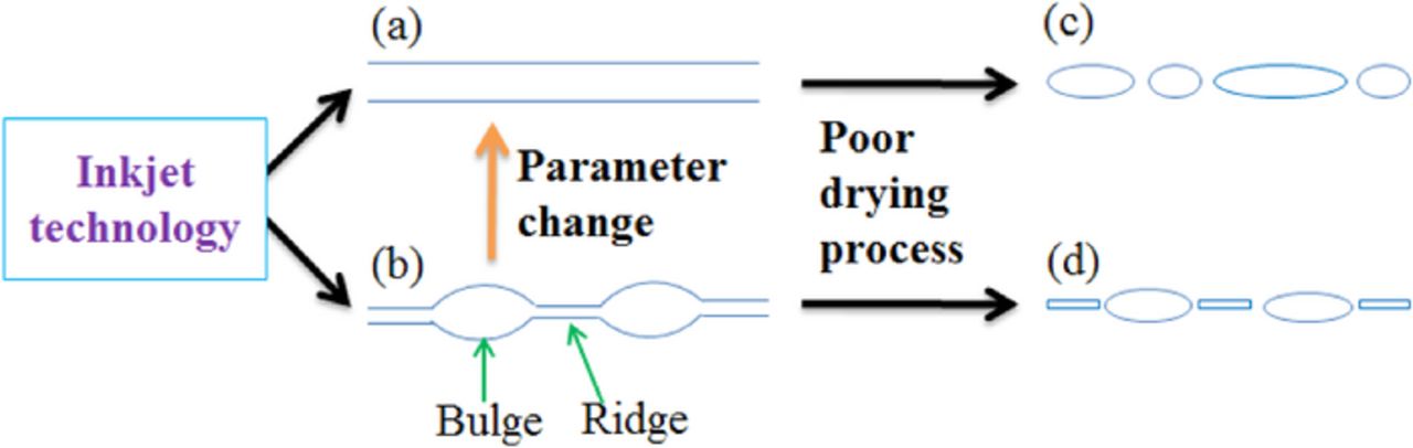
Figure 4. Instability of inkjet-printed lines can be induced by several factors. (a-b) Printing parameters, such as dot-to-dot spacing and printing speed, can result in geometrical shape variations. With careful parameter tuning, bulges and ridges on printed tracks can be avoided. (c-d) With poor drying conditions, the printed lines can be broken into pieces. Solvent adjustment or substrate heating might be necessary to avoid the shape infidelity of printed features.
Although these hydrodynamic stability analyses have greatly reduced the technical difficulties in printing micro-patterns for microelectronic devices, the predictions are limited to simple straight line geometry at constant temperature. It has been shown that with fast evaporation, the printed patterns can be faithful to the original design.76 Soltman et al. also showed that proper drop registration scheme can help preserve the pattern definition of the printed liquid films (Fig. 5),76–78 and the receding contact angles of liquids on the substrate surfaces are of crucial importance to the accuracy of printed features.79 With the addition of co-solvent adjustments, one can also adjust the contact angles to preserve the pattern definition. Lin et al.80 developed a theoretical model to explain the dewetting phenomena during the drying process of a binary solvent system, and successfully predict the contact line pinning conditions in the experiments. The optimized water/PEG solutions can then be used to prepare dye- or particle-based inks, which preserved accurate features after solvent evaporation (Fig. 6).

Figure 5. Examples of principal printed line behaviors: (a) individual drops, (b) scalloped, (c) uniform, (d) bulging, and (e) stacked coins. Drop spacing decreases from left to right.76

Figure 6. Optical images of printed circles and squares with various PEG concentrations. The dye-based ink contains 0.2 wt% Congo red. When a 10 wt% aqueous PEG solution was used, the shape definition can be maintained the same as the original design after solvent evaporation. Dotted green lines represent the original shapes for comparison.80
Drying and coffee ring effects
When ink droplets dry on a solid surface, the strong solvent evaporation at contact lines leads to aggregation of solutes or particles at pattern edges.81–84 Thus, the solute or particulate matter tend to deposit in ring-like fashion, or known as the coffee-ring effect.81,83,85 The coffee ring effect leads to a strongly non-uniform morphology and performance of patterned devices.86 To improve the uniformity of printed thin films, modification of solvent composition has been proposed to provide additional Marangoni flow to cosunteract the evaporating flux at contact lines.86–89
To date, significant progress has been achieved to effectively control the coffee-ring effects on printed features. Basically, the coffee ring formation is largely determined by the time scales of liquid evaporation and particle movement.90 For a non-volatile solvent, i.e. a long evaporation time scale, one expects no outward flow caused by solvent evaporation and thus negligible coffee ring effects. With this concept, Kim et al. used a high boiling solvent with low surface tension, such as ethylene glycol, in silver nanoparticle inks to reduce the evaporative flux to decrease coffee ring effects on printed conductive tracks.86 On the other hand, Yunker et al. also showed experimentally that the shape of suspended particles can be used to eliminate the coffee-ring effect (Fig. 7).91 Moreover, the increase in ink viscosity can lead to slow particle motion and hamper the coffee ring formation. Thus, addition of polymers in the inks can also ease the coffee-ring effects during droplet evaporation.92

Figure 7. Deposition of spheres and ellipsoids. a, b, Images of the final distributions of ellipsoids (a) and spheres (b) after evaporation. Insets, particle shape. c, Schematic diagram of the evaporation process, depicting capillary flow induced by pinned edges. Evaporation occurs over the entire drop surface (blue arrows), so if the contact line were free to recede, the drop profile would be preserved during evaporation (dashed line). However, the contact line remains pinned, so the contact angle decreases (solid line). Thus, a capillary flow (black arrows), from the drop's centre to its edges, is induced to replenish fluid at the contact line.91
In contrast to diminish the non-uniformity caused by solvent evaporation, enhanced coffee ring effects have also been used to manipulate the microstructures of conductive thin films for greater transparency. Magdassi et al.93 demonstrated that at room temperature, the replenishing flux during the evaporation of silver nanoparticle suspensions leads to compact solid aggregates near the edges of droplets. After drying, the silver deposits around coffee rings can yield an electrical conductivity as high as 15% of bulk silver. With this principle, Zhang et al. recently printed silver nanoparticle inks in various patterns, such as lines and meshes (Fig. 8), with enhanced coffee rings by adjusting substrate wettability.94 The printed rings assembly form a network composed of highly conductive silver rings and create a nearly transparent conductive thin film.

Figure 8. Schematic illustration of inkjet printing of silver-nanoparticle patterns induced by the coffee-ring effect, SEM image of the printed coffee line and the printed coffee line rim, optical image and transmittance of the glass substrate with the reticular conductive pattern.94
Adhesion and mechanical stability
The conductive tracks are regularly printed on plastic sheets, such as polyethylene terephthalate (PET) or polyimide (PI) films, to create flexible microelectronic circuits for flexible and light-weight electronic devices. To ensure satisfactory device performances, the printed conductive tracks must adhere to the substrates firmly. Tape tests95–97 are regularly performed to test the adhesion: a piece of pressure sensitive tape is applied over the printed area and removed quickly. As shown in Fig. 9a, the printed metal tracks remain totally on the plastic sheets after removing the attached tape, indicating satisfactory adhesion between the tracks and substrates. Besides adhesion, mechanical stability of the printed tracks is also needed to ensure the long term performance of "flexible" electronic devices. Fig. 9b shows a commonly used bending test method. A piece of plastic sheet with printed tracks is placed over a moving stage, which repeatedly moving back and forth to bend the sample. The change in the electronic resistance is recorded with the number of bending cycles to understand the mechanical stability of the sample tracks after being bent repeatedly. The adhesion and mechanical stability can be improved by post-treatments and addition of polymer promoters. At present, most commonly used conductive inks contain plastic binders to help the adhesion and mechanical stability of printed patterns on substrates.98 However, because binders are regularly electronically non-conductive, the addition can lead to lower conductivity. Thus, more investigation on improving the adhesion of metal tracks on plastic substrates without conductivity loss is still needed.

Figure 9. (a) Typical tape test for metal track adhesion on plastic substrates. Pressure sensitive tapes are firmly attached on the printed area (red dashed line area), and quickly removed. The completeness of the printed feature indicates the good adhesion. (b) Bending tests for mechanical stability of printed metal tracks. The resistance change after repeated bending cycles is recorded. Regularly, smaller radius of curvature leads to larger strain and hence the resistance increases quickly after several bending cycles.31,45
Potential Aspects
Smaller feature sizes with faster printing speed
To meet the demand of fast growing market in printed electronics, a printing system with good printing quality and reliability is needed. To compete with the current semiconductor processes, smaller feature sizes are required for device fabrication.98 Commercially available inkjet printing systems produce droplets in accordance to the nozzle size with a resolution of 20–30 μm.99 To obtain higher resolutions, it requires smaller size nozzles, which have manufacturing difficulties as well as worse nozzle clogging problems. On the other hand, to achieve mass production scale, the fast printing processes, which can be up to 100 m/min, require high droplet placement accuracy. However, air motion at fast printing speed also results in larger drifting velocity for smaller droplets and worsens the registration accuracy. Therefore, the quest for high resolutions at faster printing speeds with more precision and accuracy leads to the development of various non-conventional ink-jet printing methods.
One technology for getting higher resolutions and better droplet placement accuracy utilizes externally applied electric fields. The so-called electrohydrodynamic inkjet (EHD inkjet) printing technology pulls the liquid inks out of the nozzle rather than pushing inks out. As a result, EHD inkjet is capable of producing superfine ink droplets of size much smaller than the nozzle size100 with fast ejection speed (Fig. 10). The droplets size can be ∼1/10 in diameter or 1/1000 in volume smaller than conventional inkjet printers. Rogers et al. designed such a system in 2007,101 and showed the ability to produce conductive features down to sub-micrometer resolution (Fig. 11). A similar but further industrialized system called super inkjet (SIJ) technology was also developed by National Institute of Advanced Industrial Science and Technology (AIST) in Japan.98 The SIJ system can fabricate nearly sub-mircon features on any substrates. Moreover, it can be also used to create 3D conductive features as well.98

Figure 10. (a) Standard electrospinning (far-field electrospinning) to fabricate a nonwoven mat. (b) Near-field electrospinning to direct-wire fibers. (c) Medium-field electrospinning to deposit wavy structures.100

Figure 11. Nozzle structures and schematic diagrams of a high-resolution e-jet printer. a, SEM images of a gold-coated glass microcapillary nozzle (2 μm internal diameter). A thin film of surface-functionalized Au coats the entire outer surface of the nozzle as well as the interior near the tip. The insets on the right show views of this tip region. b, Nozzle and substrate configuration for printing. Ink ejects from the apex of the conical ink meniscus that forms at the tip of the nozzle owing to the action of a voltage applied between the tip and ink, and the underlying substrate. These droplets eject onto a moving substrate to produce printed patterns. In this diagram, the substrate motion is to the right.101
Electrodes on conformational surfaces or in 3D printed objects
Wearable electronic devices have recently attracted widespread attentions due to its extensive usage in the next generation electronics. For this new and emerging application, electronic devices are installed or fabricated on non-planar substrates or even 3D objects, such as contact lens, glasses, and gloves. Thus, new printing technologies for conductive tracks on curved surfaces or 3D structures are required. To date, some attempts have been tried to print conductive materials on curved surfaces using pen writing technology.102,103 For inkjet printing, it has been shown that patterns of medicines can be printed on the complicated surfaces of medical stents with special fixtures.104 Similar printing tools can be quickly extended to print conductive materials on curved surfaces, but geometry analysis for 3D surface definition and related drop registration schemes might poise challenges for printing tool development.
Another important perspective is 3D printing of conductive patterns. It was found that geometrical parameters, such as vertex shapes and aspect ratios, can effectively adjust the electron transfer efficiency or surface currents of 3D micro-structures.102 Thus, it is of great interest for scientists to design new 3D printing tools for conductive materials. This field is at the infancy stage of research, and search for new nanomaterials as well as suitable 3D fabrication tools based on wet deposition is still challenging for scientists. Magdassi et al. developed a new style of 3D conductors by using inkjet printing technology combining with UV curable ink.21 The synthesized silver nanoparticles were dispersed in water phase and mixed with the oil phase counterpart, which has UV curable characteristic. The printed patterns were exposed to UV light for 1 second and sintered by dipping the substrate into NaCl solution for 10 seconds. The as-printed silver pattern has a conductivity of 1.9 × 10⁻⁶ S m−1 within the 3D structures (Fig. 12). This new type of ink preparation with an inkjet fabrication method can provide a potential tool for 3D printing electronics.

Figure 12. Printing of a conductive 3D structure with the use of ink composed of an UV-curable emulsion and a dispersion of metal NPs.15
Acknowledgments
Ministry of Science and Technology (MOST) in Taiwan supported this research through Grants MOST 103-2923-E-002-010-MY3 and 103-2221-E-002-185-MY3.