
Abstract
Cobalt hydroxide nanoflakes with a maximum specific capacitance of 735 F/g are successfully synthesized by a facile chemical precipitation method. To enhance energy density, an asymmetric-type pseudo/electric double-layer capacitor is considered where  nanoflakes and activated carbon act as the positive and negative electrodes, respectively. The electrochemical properties of the two electrodes and the asymmetric supercapacitor are investigated in 2 M KOH aqueous electrolyte. Values for the maximum specific capacitance of 72.4 F/g and specific energy of
  are demonstrated for a cell voltage between 0 and 1.6 V. By using the nanoflake
  electrode, the asymmetric supercapacitor exhibits high energy density and stable power characteristics. The hybrid supercapacitor also exhibited a good electrochemical stability with 93.2% of the initial capacitance over consecutive 1000 cycle numbers.
Export citation and abstract BibTeX RIS
Supercapacitors combining the advantages of dielectric capacitors, which can deliver high power within a very short time, and rechargeable batteries, which can store high amounts of energy, found an increasingly important role in power-source applications such as hybrid electric vehicles, short-term power sources for mobile electronic devices, etc.1–3 However, compared to rechargeable battery systems, supercapacitors still present a very important drawback (e.g., the amount of energy density is relatively low) and precludes the extensive industrial utilization in energy storage. Recently, asymmetric or hybrid supercapacitor, regarded as the trend in electrochemical capacitors, has been reported.4–6 Asymmetric supercapacitor can be fabricated with one electrode being of a double-layer carbon material and the other electrode being of a pseudocapacitance material. It is possible to reach the high working voltage and high energy density by choosing a proper electrode material, contributed to a significant increase in the overall energy density of the supercapacitor devices.7–9
Supercapacitors make use of three main classes of materials: carbon,10, 11 metal oxide,12, 13 and electronically conducting polymer.14, 15 Among these electrode materials, activated carbon (AC) with various modifications is the electrode material used most frequently for electrodes of supercapacitors. Charge storage on carbon electrodes is predominantly capacitive in the electrochemical double layer. Carbon-based supercapacitors come close to what one would call an electrochemical double-layer capacitor (EDLC).16 The capacitance of metal oxide and conducting polymer electrode is mainly the result of the pseudocapacitance, which originated from the electrical charge transport in redox reaction. Conducting polymer capacitors have been reported to display high power densities, but their specific capacitances are much lower than that of metal-oxide capacitors. Hydrated ruthenium oxide is an excellent material with remarkable high specific capacitance values ranging from 720 to  (for single electrode system).17, 18 However, the high cost of raw materials has prevented this material from commercial applications. Therefore, in recent years, great efforts were taken to find new and cheaper materials. There are reports on cobalt oxide,19, 20 nickel oxide,21, 22 and manganese oxide.23, 24 Among the transitional base metal oxides, cobalt compound capacitors are studied as cheaper candidates with good capacitive characteristics due to its many important technological applications.
Recently, nanostructured electrode materials attracted great interest, as the capability of electrode materials for the electrochemical capacitor system is significantly influenced by its surface area and morphology, thereby the synthesis of nanostructured, high surface area, and high porous materials is an important point because the high surface area produces the large reaction place and many pores cause rapid transfer of the electrolyte.25 Therefore, a great amount of research work has been done to improve the electrochemical performance of cobalt oxides by preparing nanostructured cobalt oxides. We reported a chemical precipitation method to prepare cobalt hydroxide nanoflakes with a maximum specific capacitance of 735 F/g (the specific capacitance is calculated at a current density of  with a potential window from −0.2 to 0.4 V) and demonstrated its potential application in electrochemical capacitors.26 Unfortunately, the cobalt hydroxide material has a narrow operation potential (the real galvanostatic discharge window is about 0.5 V), and it is thereby limited to practical applications because of energy density. In this work, we first introduced this
  nanoflake material as a positive electrode to fabricate an asymmetric supercapacitor in combination with AC as the negative electrode in 2 M KOH electrolyte solution. The primary electrochemical characterization was investigated by cyclic voltammetry (CV) and galvanostatic charge/discharge test. The effect of the microstructure on its electrochemical performance of the prepared material has also been systematically investigated.
Experimental
Preparation of the  materials

All of the chemicals were of analytical grade and were used without further purification.  materials were prepared by a facile-improved precipitation method. The first step was the confecting of cobalt chloride hydrate solution (the solution
  ; Co
; Co  ) in a glass beaker using a magnetic stir bar. The cobalt chloride hydrate solution was slowly adjusted to pH 9 by the dropwise addition of 5 wt %
  (about 30 mL) at a temperature of
  . The
. The  solution was added dropwise with a constant time interval of 5 s. The resulting suspension was stirred at this temperature for an additional 3 h. Then the solid was filtered and washed with a copious amount of distilled water several times. The obtained product was dried at a temperature of
  in air for 6 h. In comparison with the
  nanoflake materials, we prepared usual grain
  materials by the same method, but used NaOH instead of
  . Without special denotation, the
  sample is referred to as the
  nanoflake materials in this work.
The morphologies of  materials were characterized by transmission electron microscope (JEOL, JEM-2010, Japan), field-emission-scanning electron microscope (JEOL, JSM-6701F, Japan), X-ray diffraction (XRD) measurements (Rigaku, D/Max-2400, Japan), and nitrogen adsorption and desorption experiments (Micromeritics, US, ASAP 2010M). The surface area was calculated using the Brunauer–Emmett–Teller (BET) equation. Pore size distributions were calculated by the Barrett–Joyner–Halenda (BJH) method using the desorption branch of the isotherm. Commercial AC (The ShaoWu XinSen Carbon Company, China, with a specific surface area of
  and a diameter of
  ) was used as the negative electrode material without further treatment.
Preparation of the electrode
The working electrodes were prepared according to the method reported in Ref. 23.  powder (80 wt %) was mixed with 7.5 wt % of acetylene black
  and 7.5 wt % of conducting graphite in an agate mortar until a homogeneous black powder was obtained. To this mixture, 5 wt % of poly(tetrafluoroethylene) was added with a few drops of ethanol. After briefly allowing the solvent to evaporate, the resulting paste was pressed at 10 MPa to a nickel gauze with a nickel wire for an electric connection. The electrode assembly was dried for 16 h at
  in air. The AC electrodes were prepared by the same method as the negative electrode described above.
Electrochemical test of the single electrode and asymmetric supercapacitor
The electrochemical measurements of single  and AC electrodes were carried out using an electrochemical working station (CHI660C, Shanghai, China) in a three-electrode cell at room temperature. A platinum gauze electrode and a saturated calomel electrode (SCE) served as the counter and the reference electrode, respectively. Each electrode contained about 8 mg of electroactive material and had a geometric surface area of about
  .
.
The  cathode and AC anode were pressed together and separated by a porous nonwoven cloth separator. The mass ratio of active materials (anode/cathode) was 8.7:8 mg. Each electrode had a geometric surface area of about
  . The electrochemical measurements of the asymmetric supercapacitor were also carried out using the electrochemical working station in a two-electrode cell at room temperature.
The specific capacitance of the asymmetric capacitor can be evaluated from the charge/discharge test together with the following equation

where  is the specific capacitance,
  is the constant discharging current,
  is the time period for the potential change
  , and
, and  is the mass of the corresponding electrode materials measured.
The charge on the electrode can be evaluated from the charge/discharge test together with the following equation
where  is the constant discharging current,
  is the time period for the potential change, and
  is the mass of the corresponding electrode materials measured.
The real power density  is determined from the constant current charge/discharge cycles as follows27

where  with
with  is the potential at the end of the charge and
  at the end of the discharge,
  is the applied current (A), and
  is the weight of the active material in the electrode (kg).
The specific energy  is defined as

where  is the system capacitance (F/g) for a cell and
  is the maximum cell voltage.
Results and Discussion
Characterization of materials

To identify the crystal structure of the original  material and its corresponding sample after the electrochemical test in KOH solution, we measure the XRD pattern of the
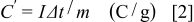
  material and its corresponding sample after immersion, kept in the 2 M KOH solution at room temperature for 12 h. As shown in Fig. 1a, no obvious peaks of
  have been observed in the XRD pattern of the as-prepared
  material, and it corresponds to the layered
  structure (PDF card no. 46-0605) with low crystallinity.28 All the diffraction peaks of Fig. 1b agree with the admixture of
  (PDF card no. 30-0443) and CoOOH (PDF card no. 07-0169). The result shows that the biggest part of the
  was converted to
  , while the smaller part was converted to CoOOH with
  by immersion into the KOH solution. The oxidation from
  to
to  of cobalt in cobalt hydroxide by oxygen in the KOH solution is reported because the stability of
  in KOH solution is well known.29 Due to the high conducting CoOOH phase, the obtained electrode not only possesses a high specific capacitance but also exhibits a well rate capability.
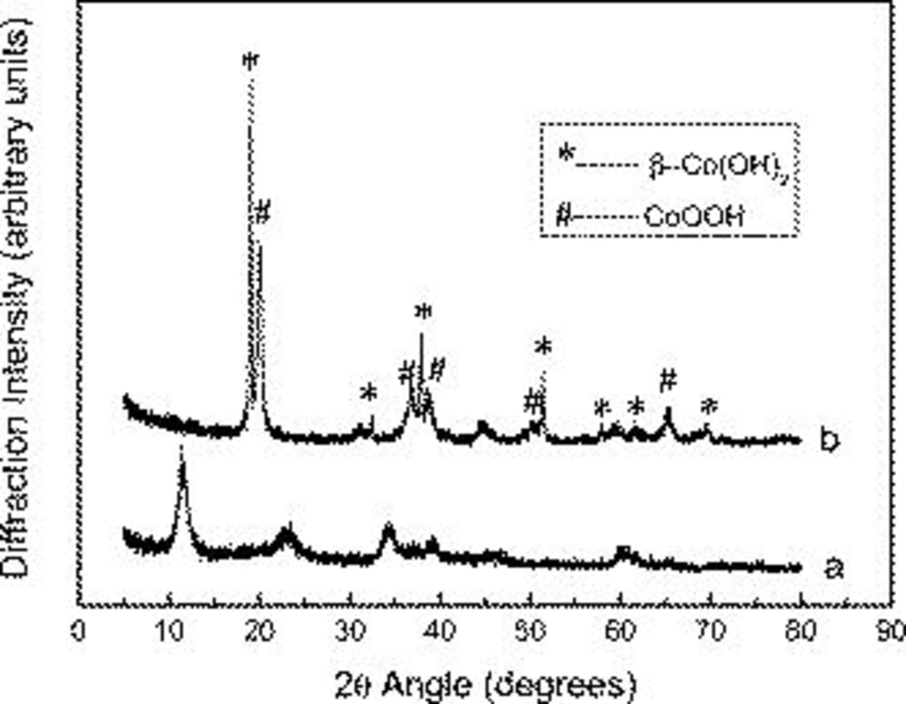
Figure 1. The XRD patterns of the (a)  and (b)
  samples after immersion, kept in the 2 M KOH solution at room temperature for 12 h.
Scanning electron microscopy (SEM) and transmission electron microscopy (TEM) measurements were performed to the as-prepared nanoflake  and usual grain
  materials. The morphologies of nanoflakes
  are shown in Fig. 2a and 2b. The networklike structure, which consists of interconnected nanoflakes, shows anisotropic morphology characteristics and the formation of a loosely packed microstructure in the nanometer scale. The unique structure plays a basic role in the morphology requirement for electrochemical accessibility of electrolyte
  to
to  active material and a fast diffusion rate within the redox phase. As shown in Fig. 2c, usual grain
  materials have a morphology of granular particles with a typical particle diameter of about 500 nm.
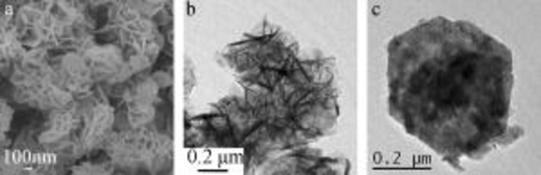
Figure 2. (a) SEM and (b) TEM images of nanoflake  materials. (c) TEM image of the usual grain
  materials.
Surface area and pore-size distribution analysis of the  materials were conducted using
  adsorption and desorption experiments. As shown in Fig. 3, the profile of the hysteresis loop indicates an adsorption–desorption characteristic of the porous materials. The BET specific surface area of the
  materials was
  . The inset is the pore diameter distributions of the
  sample. As shown in this figure, the
  materials possess a narrow mesoporous distribution at around 4–20 nm. Because the size range of the hydrated ions in the electrolyte is typically
  , and the pore size at the range of
  is the effective one required to increase either the pseudocapacitance or electric double-layer capacitance,30 the obtained high specific capacitance of the synthesized
  materials is mainly attributed to the effective distributions of the pore size and the high specific surface area.
Figure 3. The  adsorption–desorption isotherm of
  materials; the inset is the BJH pore-size distributions of
  materials.
The electrochemical characterizations of the material and AC

To evaluate the electrochemical properties of the prepared  material and the commercial AC, we directly use these two materials to fabricate electrodes for supercapacitors. CV and chronopotentiometry measurements have been used to evaluate the electrochemical properties and quantify the specific capacitance of the
  and AC electrodes. CV curves for AC and
  electrodes in 2 M KOH aqueous solution are shown in Fig. 4. The AC electrode was performed within a potential window of −1.0 to 0 V (vs SCE), and
  was employed within a potential window of 0–0.4 V (vs SCE) at a scan rate of 5 mV/s. For the AC electrode, a nearly rectangular CV curve is obtained, indicating a typical electric double-layer capacitor behavior because no peaks of oxidation and reduction are observed. The CV shapes of
  reveal that the capacitance characteristic is very distinguished from that of the electric double-layer capacitance; two redox peaks are clearly observed. The positive polarization of
  could be limited by
  evolution because of water decomposition from the electrolyte. Similarly, the negative polarization of AC could also be limited by
  evolution.31
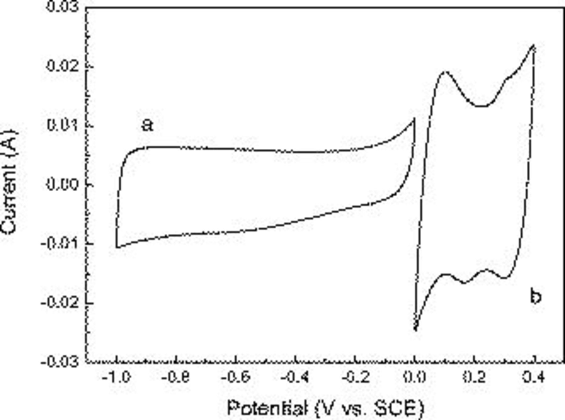
Figure 4. Cyclic voltammogram of (a) AC and (b)  electrodes at a scan rate of 5 mV/s in 2 M KOH solution.
Figure 5a shows the typical galvanostatic charge/discharge curves of the  nanoflake electrode and the usual
  particle electrode within a potential window of 0–0.4 V at a current density of
  . The shape of the discharge curves does not show the characteristic of a pure double-layer capacitor, but mainly pseudocapacitance, which agrees with the result of the CV curves. The slope of charge/discharge curves indicates the potential-dependent nature of the faradaic reaction. The charges on the
  nanoflake electrode and the usual
  electrode in the potential window of 0–0.4 V are 192 and 37.5 C/g, respectively, according to Eq. 1. The unique nanoflake structure provided an important morphological foundation for the extraordinary high specific capacitances. The linear charge/discharge curves are observed in Fig. 5b of the AC electrode within a potential window of −1 to 0 V at a current density of
  . The linear shape of the curve is attributed to the linear correlation of the absorbed charge on the interface with the applied potential. That means the specific capacitance is independent of the applied potential nature, distinctly accompanied with a nonfaradaic process on the interface. The charge on the AC electrode is 176 C/g in the potential window of −1 to 0 V; therefore, the optimal mass ratio of the
  electrode and the AC electrode is 176:192, and the loads of the cathode
  electrode and the AC anode electrode materials are of 8 and 8.7 mg, respectively.
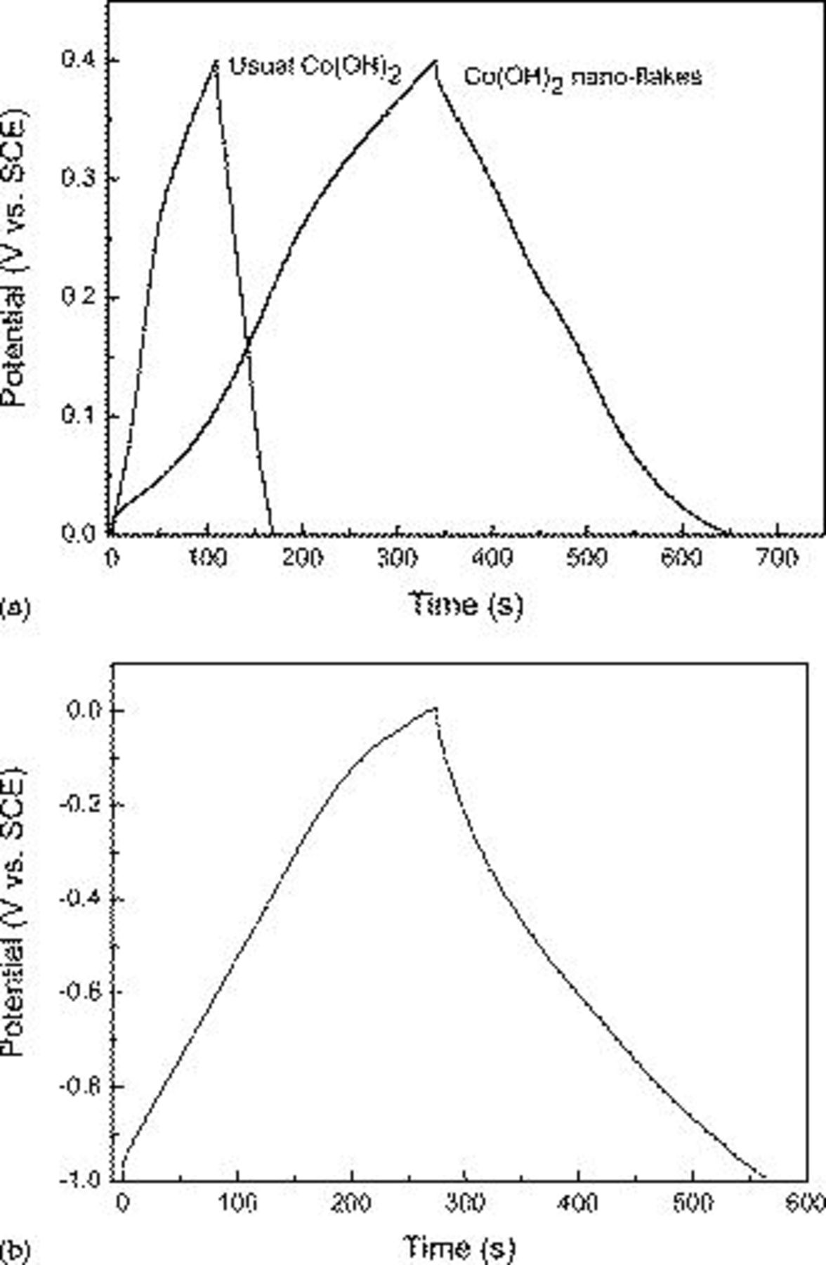
Figure 5. Charge/discharge curves of the (a) nanoflake  electrode and usual grain
  electrode in the potential window of 0–0.4 V and (b) AC electrode in the potential window of −1 to 0 V at a current density of
  in 2 M KOH solution. Each electrode contained about 8 mg of electroactive material and had a geometric surface area of about
  .
.
The electrochemical characterizations of the asymmetric capacitors
It is very important to polarize each electrode at the same potential before cycling the device; otherwise there is a risk of damaging the cell during the first cycles. The typical CV of the asymmetric capacitor at voltage scan rates of 2.5, 5, and 10 mV/s is depicted in Fig. 6a. The hybrid device was cycled between 0 and 1.6 V with a good reversibility in this potential window. At a fully oxidized state,  gives about 0.6 V, but the AC electrode gives about −1 V at a fully reduced state, whereas the discharge process proceeds until the potential of both electrodes is the same. Thus, the potential of the asymmetric unit cell can reach 1.6 V in the fully charged state. With the sweep rate increased, the shape of the CV changed, the anodic peak and cathodic peak potential shift in the more anodic and more cathodic direction, and the capacitance inevitably decreased, which agrees with the result of chronopotentiometry measurement.
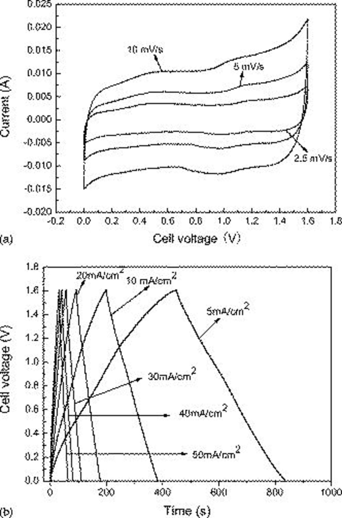
Figure 6. Electrochemical properties of the asymmetric supercapacitor in 2 M KOH solution within a potential range from 0.0 to 1.6 V: (a) Cyclic voltammograms at different scan rates and (b) charge/discharge behavior at different current densities. The mass loads of the cathode  electrode material are 8 and 8.7 mg of the AC anode electrode material.
Galvanostatic constant current charge/discharge measurements at different current densities were applied to evaluate the electrochemical properties and to quantify the specific capacitance of the asymmetric supercapacitor in 2 M KOH electrolyte. Figure 6b shows the typical galvanostatic charge–discharge curves of the hybrid capacitor between 0 and 1.6 V at different current densities. As shown in Fig. 6b, during the charging and discharging steps, though an almost linear variation in the cell voltage is observed in the curves, perfect linear curves are not obtained compared with EDLC. This is due to a typical pseudocapacitance behavior resulting from the electrochemical adsorption/absorption or redox reactions at interfaces between electrodes and electrolyte.27 Because the real galvanostatic discharge window of the  electrode is about 0.5 V, the result of the present work shows that it is possible to reach the high working voltage by choosing a proper electrode material. Furthermore, as the discharge current increases, the large voltage drop is produced and finally the capacity decreases. This phenomenon may be explained by referring to
  ion diffusion processes during the charging/discharging for the electrode. When the electrode at high sweep rates corresponds to a high current density, massive
  ions are required to intercalate swiftly at the interface of the electrode/electrolyte. However, a relatively low concentration of
  ions could not meet this demand, and the processes would be controlled by the ion diffusion.32
In comparison with the asymmetric capacitor, we fabricate a two-electrode AC symmetric capacitor and it is cycled galvanostatically between 0 and 1.0 V. Each electrode contained about 8.7 mg of AC material and had a geometric surface area of about  . Figure 7 shows the specific capacitance of the double-electrode cell as a function of the discharge current density for the
  electrode-based asymmetric supercapacitor and the AC-based EDLC. The specific capacitances of the hybrid capacitor of the total weight of the active material for both electrodes at 5, 10, 20, 30, 40, and
  were 72.4, 68.3, 63.7, 60.7, 59.1, and 56.8 F/g, respectively. The specific capacitances of the EDLC of the total weight of the active material for both electrodes at 5, 10, 20, 30, 40, and
  were 30.9, 29.3, 26.9, 25.6, 24.5, and 23.7 F/g, respectively. The results show that the specific capacitance of the asymmetric supercapacitor is much higher than that of the EDLC. Even though under the large current density of
  , nearly 78.5% of the initial amount can be reached for the hybrid capacitor, so the large specific energy and excellent rate capability of the asymmetric capacitor make it attractive particularly for a practical application. This all demonstrates that the unique microstructure creates an electrochemical accessibility of electrolyte
  ions to
  nanoflakes and a fast diffusion rate within the redox phase.
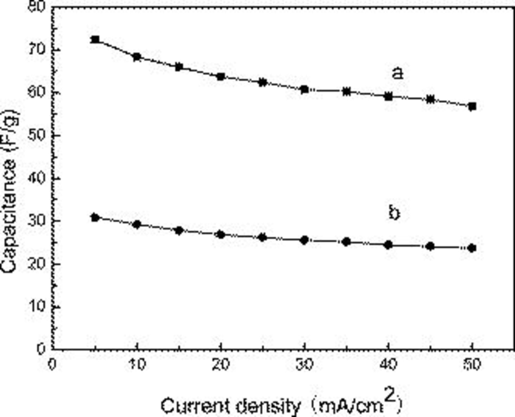
Figure 7. Specific capacitance as a function of discharge currents for (a) asymmetric supercapacitor and (b) AC-based EDLC capacitor.
To highlight the electrochemical performance of the hybrid supercapacitor based on  and AC electrodes, the Ragone plot relating real power density to energy density of the asymmetric supercapacitor and the EDLC is also demonstrated in Fig. 8. The energy and power data are calculated when taking account of only the mass of the electrode material. Clearly both the energy and power densities greatly increased compared with the EDLC type. This can be explained by the energy and power densities, which critically depend on the real working voltage. The energy density of the asymmetric supercapacitor increases from 72.7 to 92.7 Wh/kg when the real power density decreases from 2395.2 to 239.5 W/kg. The specific energy increases by more than 6 times compared with that of a symmetric AC-based EDLC capacitor using an aqueous KOH electrolyte.
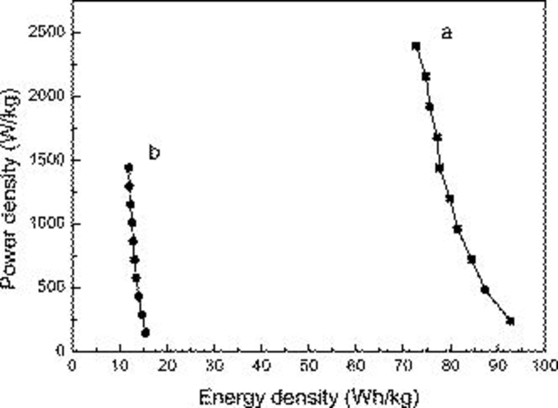
Figure 8. Ragone plot relating power density to achievable energy density of (a) asymmetric supercapacitor and (b) AC-based EDLC capacitor.
The cycling stability of the asymmetric supercapacitor was performed by charge–discharge at a current density of  within a voltage range of 0−1.6 V in the 2 M KOH electrolyte. As shown in Fig. 9, the capacitance of the hybrid supercapacitor decreases with the growth of the cycle number. After a continuous 1000 cycles, the capacitance value remains 93.2% of that of the first cycle. The attenuation of the capacitance just for 6.8% suggests the good stability of the
  asymmetric supercapacitor, which is significant for the practical application.
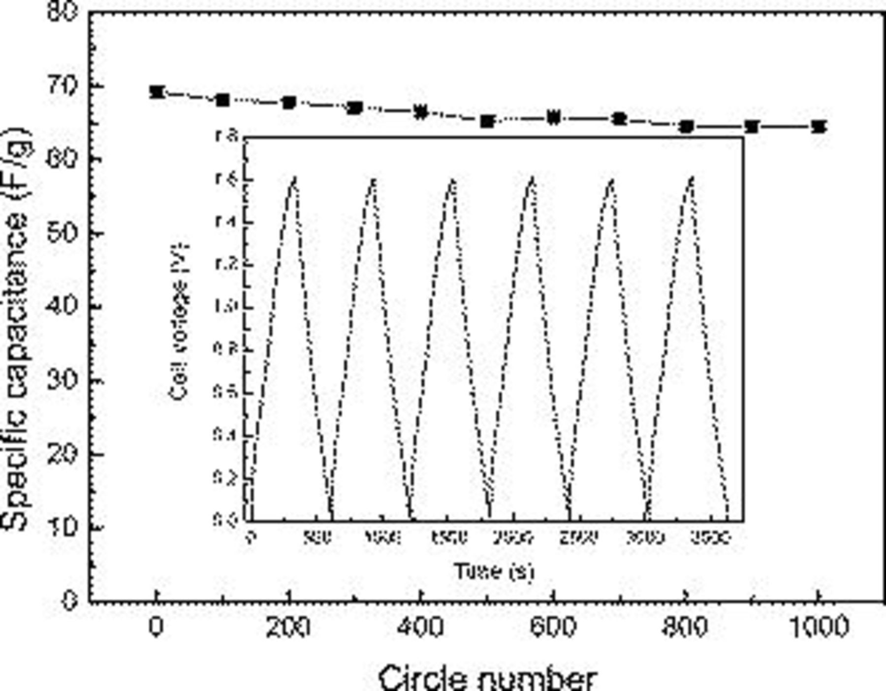
Figure 9. Cycle life of the asymmetric supercapacitor at the current densities of  . The inset is charge/discharge curves of the asymmetric supercapacitor.
Conclusions
In summary, loose-packed  materials consisting of a nanoflake network with a high specific capacitance was obtained using a facile chemical precipitation method. An asymmetric supercapacitor based on
  as the positive electrode and AC as the negative electrode with high operating voltage, high energy density, and maximum power density was fabricated in the 2 M KOH electrolyte. The specific capacitance and specific energy of the cell reached 72.4 F/g and 92.7 Wh/kg within the potential range of 0–1.6 V, respectively. The hybrid supercapacitor also demonstrated a good cycling performance with an attenuation of capacitance of 6.8% over 1000 cycle numbers.
Acknowledgments
This work was supported by the National Natural Science Foundation of China (no. 50602020), the Natural Science Foundation of Gansu Province (no. 0803RJZA002), and the Program for Outstanding Young Teachers in Lanzhou University of Technology (no. Q200803).
Lanzhou University of Technology assisted in meeting the publication costs of this article.