Abstract
Carbon black was employed as the catalyst for triiodide reduction on fluorine-doped tin oxide glass substrates (FTO-glass) used as counter electrodes in platinum-free dye-sensitized solar cells. The fill factors were strongly dependent on the thickness of the carbon layer, and the light energy conversion efficiency also increased up to a thickness of  . The charge-transfer resistance
  of the carbon counter electrode decreased with the thickness of the carbon layer. The
  for the thicker carbon layer is less than three times that for the platinized FTO-glass. The highest cell efficiency was 9.1% under
  light intensity (1 sun AM 1.5 light,
  ,
,  , fill
  ).
).
Export citation and abstract BibTeX RIS
Solar energy conversion efficiencies of dye-sensitized solar cells (DSCs) have reached 11%,1–3 rendering it a credible alternative to other thin-film photovoltaic cells.4 DSCs are well known as low cost photovoltaic devices that have a short time for energy payback. However, further cost reduction is warranted5 in addition to the need for further increasing the efficiency.6, 7 These issues have been addressed by industrial and academic research,8–13 and several strategies allowing for lowering the cost have been made. For instance, the application of conductive plastic substrates, based on polyethylene terephthalate (PET) or polyethylene naphthalate (PEN) films, to DSCs reduces the cost through mass production by employing role-to-role manufacturing system.14–19 Organic dyes may afford a cut in sensitizer cost.20, 21 The counter electrode is an equally important component of the DSC.5 Usually fluorine-doped tin oxide (FTO) glass is loaded with platinum to facilitate electron exchange with the iodide/triiodide ions redox couple,1–3 which would corrode metals such as aluminum, iron, and nickel.22–26 While the amount of Pt necessary to obtain the desired catalytic effect is very small, i.e., ca.  and hence does not contribute significantly to the overall price per peak-watt, future large solar conversion systems producing electric power on the terawatt scale will prefer materials that are abundantly available. There are also some reports of corrosion of Pt in triiodide-containing solutions generating platinum iodides such as
  ,5, 27 although other long-term studies did not reveal degradation of counter electrode performance during thermal stress and light soaking, indicating that the stability of the FTO-supported Pt catalyst depends on the mode of preparation. It is desirable to develop alternative cheap materials for the counter electrodes which should be corrosion-inert and exhibit good catalytic activity for the reduction of the triiodide ion. Several previous reports already describe Pt-free counter electrodes for the DSC. In 1996, Kay and Grätzel achieved a conversion efficiency of 6.7% using a monolithic DSC embodiment based on a mixture of graphite and carbon black as current collector.5 Furthermore, in recent years, several varieties of carbonaceous materials such as carbon nanotubes,28 carbon black, activated carbon, and graphite5, 15, 29 have also been employed as catalysts on FTO-glass for counter electrodes. In the case of carbon nanotubes, the material could be used as the counter electrode without a conductive substrate. Organic ion-doped conducting polymers based on poly(3,4-ethylenedioxythiophene) (PEDOT) were used as catalytic materials on both ITO- and FTO-glass for cells with both organic and ionic liquid electrolytes.30, 31 While the cost of carbon nanotubes and conducting polymers is lower than that of Pt, lack of adhesion to the transparent conducting oxide (TCO) substrate poses a long-term stability risk. Furthermore, the conversion efficiencies of the cells using carbon materials as counter electrodes are still insufficient and should be increased to more than 8% for practical usage.
Carbon blacks are used on a large scale, for example in printing toners, and cheap industrial mass production methods are already in place. They are electrically conducting and show catalytic activity for the reduction of triiodide.32–34 The active sites for catalysis in carbon materials are located at the crystal edges. Consequently carbon blacks having low crystallinity and many edges may be more active than highly orientated carbon materials such as graphite and carbon nanotubes. When we apply a carbon material as the counter electrode, the layer thickness will be important because it affects both catalysis and resistance. Although such effects have been scrutinized for platinum,35, 36 systematic investigations on carbon black counter electrodes have been lacking so far and are presented in this paper.
Experimental
In the present work, preparation of chemicals, materials,  mesoporous layer, and platinized FTO-glass basically followed our previous reports in Ref. 7.
Chemicals and materials
F-doped  coated glass (FTO-glass) as transparent conductive glass for photoelectrodes and counter electrodes were supplied from Nippon Sheet Glass Co. Ltd.
  and LOF Industries
  . These substrates were used after cleaning by sonication in acetone (Fluka). The
  paste of nanocrystalline anatase (particle size:
  for transparent dye coated layer and
  for scattering layer) was prepared by our previous method in Ref. 37. Ru complex dye, cis-bis (isothiocyanato) bis (2,
 -bipyridyl-4,
 -dicarboxylato)- ruthenium(II) bis-tert-butylammonium (N-719), was synthesized as previously described.38 The N-719 dye was adsorbed from a
  solution in a mixed solvent of acetonitrile and tert-butyl alcohol (volume ratio: 1:1). The electrolyte was a solution of
  1-methyl-3-butylimidazolium iodide,
 (Merck),
  guanidinium thiocyanate (Aldrich), and
  4-tert-butylpyridine (Aldrich) in mixed solvent of acetonitrile (Fluka) and valeronitrile (Fluka, volume ratio: 85:15). The 1-methyl-3-butylimidazolium iodide was synthesized as described in Ref. 39.
Preparation of the mesoporous  layer
layer

Preparation of mesoporous  films followed a previously described method.7 First, a
  thick transparent film of
  -sized
  particles was screen printed on the FTO-glass substrates and this was covered by a second
  thick layer of
  sized
sized  scattering particles. The electrode was sintered in dry air at
  for
for  and
and  for
for  . Before screen printing, the FTO-glass was immersed in
  of
of  aqueous solution at
  for
for  and the same treatment was also done after sintering of the
  double layers. For the dye adsorption, the layers were immersed into the dye solution during
  at room temperature, immediately after reheating the layers at
  for
for  .
.
Preparation of carbon counter electrodes
To obtain the carbon paste,  of the carbon powder (Printex L, Degussa) was ground in a mortar with
  of
of  colloid,
  of water, and
  of 10% Triton X-100 aqueous solution. The
  colloid was prepared as reported:5, 40
  of
of  with
with  of isopropanol was dropwise added to
  of water under stirring. After addition of 65% nitric acid
  and heating the solution at
  for
for  under stirring, the
  precipitate was peptized to a white transparent colloid.
The carbon paste was coated on FTO-glass by doctor-blading. The substrate was dried for  at room temperature and then heated in air at
  for
for  . The FTO-glass has a small hole for subsequent electrolyte injection. After heating, the thickness of the carbon layer was measured in two perpendicular directions with a surface profilometer (Alpha-step 200, Tencor Instruments). The average of both measurements was taken as the thickness of the carbon layer. The relative surface area and the pore volume of the carbon layer were measured by nitrogen gas adsorption methods with ASAP 2000 of Micromeritics.
Preparation of platinized FTO-glass electrodes
The same FTO-glass substrates were coated with a solution of  (
( in isopropanol) and heated in air at
  for
for  .
.
Assembly of the DSC
The photoelectrode and counter electrode were sandwiched with a  thick spacer of the thermo-bonding polymer (Surlyn, DuPont) and heated for sealing. When the thickness of carbon layer was over
  , a double layer of the spacer film was inserted between the two electrodes. After sealing, the electrolyte was injected between the electrodes through the hole in the counter electrode, and then the hole was sealed with Surlyn and cover glass.
Assembly of the dummy cell for impedance spectroscopy
The platinized FTO-glass and carbon counter electrode were sandwiched with insertion of a triple-layer film of Surlyn and heated for sealing. The electrolyte injection and final sealing were carried out in the same way as for other DSCs.
Measurements of photocurrent-voltage curves and impedance spectra

Photocurrent-voltage characteristics were measured with a Keithley 2400 source meter under illumination from a solar simulator composed of a  xenon arc lamp (Oriel) and AM
  filters. Light intensity was calibrated with a silicon photodiode. Impedance spectra were acquired with a computer-controlled potentiostat (EG&G, M273) equipped with a frequency response analyzer (EG&G, M1025). The measured frequency range was
  to
to  . The obtained spectra were fitted with Z-View software (v2.8d, Scribner Associate, Inc.) in terms of the proposed equivalent circuit (Fig. 7 and 9).

Figure 7. Equivalent circuit diagram used to fit the observed impedance spectra in Fig. 6. 
 : Charge-transfer resistance of
  interface or carbon-FTO interface;
 : Charge-transfer resistance of dye-sensitized
  layer;
 : charge transfer resistance of counter electrode such as carbon coated FTO-glass; CPE (solid): constant phase element of
  interface or FTO-carbon interface;
  : serial resistance;
 : constant phase element of dye-sensitized
  layer; CPE (CB): constant phase element of carbon coated FTO-glass;
  : Warburg impedance.

Figure 9. Equivalent circuit diagram to fit the observed impedance spectra in Fig. 9. 
 : Charge-transfer resistance of platinized FTO-glass;
 : charge-transfer resistance of carbon-coated FTO-glass;
  : serial resistance; CPE (Pt): constant phase element of platinized FTO-glass; CPE (CB): constant phase element of carbon-coated FTO-glass;
  : Warburg impedance.
Results and Discussion
A schematic diagram of the DSCs used in this study is shown in Fig. 1. We prepared carbon layers of various thicknesses on FTO-glass substrates as counter electrodes by doctor-blading the coated area of the FTO-glass to  . We then measured the performance of the DSCs using these carbon-coated FTO-glass substrates as counter electrodes. Figure 2 shows the scanning electron microscopy (SEM) image of the carbon layer, which is composed of 93% carbon and 7% (w/w)
  . The film has a porous structure with
  average particle size. The Brunauer-Emmett-Teller (BET) surface area of this layer is
  . The Barrett-Joyner-Halenda (BJH) average pore diameter and pore volume are
  and
and  , respectively. This means that a carbon layer of
  geometric area and
  thickness has
  of active surface area and a porosity of 57%. The relation between layer weight and the thickness is shown in Fig. 3.

Figure 1. Scheme of the dye-sensitized solar cell with carbon counter electrode in cross-sectional view.

Figure 2. SEM image of the carbon layer for the counter electrode.

Figure 3. Relation between thickness of the carbon layer on FTO-glass and the weight of the carbon layer.
Photovoltaic results are shown in Fig. 4. The short-circuit photocurrent  is unaffected by changes in the thickness of the carbon layer on the counter electrode from 1 to
  and the average value is
  (Fig. 4A). The open-circuit voltage
  decreases slightly with an increase in the thickness of the carbon layer (Fig. 4B). The two possible explanations of the latter observation are a pH decrease due to adsorption of the 4-tert-butylpyridine from the electrolyte to the carbon surfaces, or a localized short-circuiting between
  layer and carbon black particles. The most pronounced change is observed in the fill factor (FF), which increases from 46 to 72% with an increase in the thickness of the carbon layer up to
  (Fig. 4C). For layers thicker than
  the FF remains constant at around 70%. Figure 4D shows that the conversion efficiency increases with the thickness of the carbon film. Clearly this effect is linked to the improvement in the FF. It is instructive that cells using bare FTO-glass as counter electrodes without any catalyst performed very poorly, the photovoltaic parameters being
 ;
; 
 ; FF 6%; efficiency 0.02%. The necessity of depositing an effective catalyst onto the FTO counter electrode can easily be appreciated from this result.
  curves for each thickness of the carbon layer are shown in Fig. 5 and the performance of these cells is listed in Table I. The highest efficiency was 9.1% for a
  thick layer of carbon. For thin films, the photocurrents are attenuated at voltages above
  , but the
  values of all the curves converge at around
  . Note that the photocurrent for carbon layers of 3.09, 2.14, and
  thickness decreases exponentially with forward bias voltage near the
  . This can be attributed to overvoltage losses due to insufficient catalytic activity for the reduction of triiodide of the thinner carbon layers. Similar
  curves have been previously observed with carbon or conductive polymers as counter electrodes.29, 30

Figure 4. Relation between thickness of the carbon layer on FTO-glass as counter electrode and performances of dye-sensitized solar cells for short-circuit photocurrent  , open-circuit photovoltage
  , fill factor (C), and photoenergy conversion efficiency (D). N719 was used as photosensitizing dye and the electrolyte used was a solution of
  1-methyl-3-butyl-imidazolium iodide,
 ,
,  guanidinium thiocyanate,
  4-tert-butylpyridine in a mixed solvent of acetonitrile and valeronitrile (volume ratio: 85:15). The coated areas of
  layer and carbon layer are 0.16 and
  , respectively.

Figure 5. Typical photocurrent-voltage curves of cells using various thickness of carbon layer as counter electrodes. Area of electrodes, sensitizing dye, and electrolyte composition are the same as that in Fig. 4.
Table I. Photoelectric performances of the cells in Fig. 5.
| Thickness (μm) |

|

| FF (%) | η (%) |
|---|---|---|---|---|
| 14.47 | 16.8 | 790 | 68.5 | 9.1 |
| 9.79 | 16.8 | 770 | 64.6 | 8.4 |
| 4.73 | 16.9 | 760 | 64.1 | 8.2 |
| 3.09 | 16.5 | 769 | 59.3 | 7.5 |
| 2.14 | 16.2 | 772 | 55.2 | 6.9 |
| 0.85 | 16.2 | 769 | 46.3 | 5.8 |
To find the cause of the improvements in cell performance with carbon thickness, we measured the charge-transfer resistance for triiodide reduction on the carbon layer by impedance spectroscopy. Nyquist plots are shown in Fig. 6 for DSCs with carbon layer thicknesses of 0.53, 1.8, and  and a conventional platinized FTO-glass as counter electrode. The cells were measured at a forward bias of
  , which is close to the
  . The spectra were fitted to the equivalent circuit shown in Fig. 7 featuring three RC elements, a Warburg impedance to describe the electrolyte diffusion, and a series resistance. The three RC elements depict the electric response of the carbon/electrolyte,
  /electrolyte, and electrolyte, interfaces, and solid-solid contact between FTO and the carbon or between FTO and the
  . The diffusion impedance for electrons in the
  layer can be neglected at a bias of
  . For the thinnest carbon counter electrodes, a large arch due to impaired electron transfer at the counter electrode is visible in the low-frequency region of the Nyquist diagram, which decreases with increasing film thickness. Note that the arch for the electrolyte diffusion is hidden by the large charge-transfer resistance on
  .
.
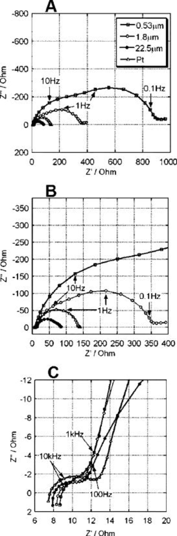
Figure 6. Nyquist plots of DSC with different thicknesses of the carbon layer on FTO-glass as counter electrode and with the conventional platinized FTO-glass. The cells were measured in dark with an applied voltage at  . B and C are expanded range of the ordinate and abscissa from A and B.
The circuit elements are comprised of a charge-transfer resistance  , constant phase element (CPE), Warburg impedance
  , and series resistance
  .
.  is the electron transfer resistance at the interface.41 The CPE reflects the interfacial capacitance, taking into account the roughness of the electrodes causing a depression of the semicircle to an ellipse in the Nyquist plots.36, 42, 43 The impedance of CPE is described as
  .
.  and α are frequency-independent parameters of the CPE. If the semicycle is depressed α approaches 0. The exact semicircle should give
  and the CPE behaving the same as a simple capacitor. α indicated the capacitance of CPE and the deviation from the semicircle probably due to the porosity of electrode surface, respectively.
  is described as a finite diffusion length in the electrolyte, and
  indicates the ohmic resistance of the FTO layer, the
  layer, the carbon layer, and the electrolyte. In the spectra of cells with carbon electrodes, the first high-frequency arch
  is likely to arise from the solid-solid interface and the second arch, around
  , is the charge transfer resistance of the carbon. The third arch, around
  , is charge-transfer resistance on
  . In the case of platinized electrodes, we cannot see the arch from the solid-solid interface because the contact between Pt and FTO is not ohmic. Table II shows the estimated values for the charge-transfer resistance on carbon and on
  , and also the CPE parameters for both interfaces. The thick carbon layer decreases the charge-transfer resistance of the counter electrodes from 118 to
  . The charge-transfer resistance of
  decreases with the thickness of the carbon regardless of the condition of
  layer. This unexpected result indicates shunting from the spillover of carbon from the counter electrode to the photoanode. The highly porous thick carbon layer is also reflected in the depressed semicircle in the Nyquist plot and also on the low α number of the CPE 0.81. In these impedance results, the thicker carbon layer decreased the charge-transfer resistance of the counter electrode and improved overall cell performance.
Table II. Impedance parameters of the DSC with conventional platinized FTO-glass as counter electrodes and the carbon counter electrodes for various thickness estimated from impedance spectra in Fig. 6 and equivalent circuit in Fig. 7.
| Catalyst on FTO-glass |
 ( ( ) ) | CPE(CB):A ( ) ) | CPE
|
 ( ( ) ) |
 
|
 α α |
|---|---|---|---|---|---|---|
| Heat-deposited platinum | 1.06 |

| 0.98 | 19.4 |

| 0.93 |
 thickness of carbon thickness of carbon | 0.74 |

| 0.81 | 9.00 |

| 0.88 |
 thickness of carbon thickness of carbon | 28.6 |

| 0.97 | 36.2 |

| 0.94 |
 thickness of carbon thickness of carbon | 118 |

| 0.89 | 86.6 |

| 0.93 |
Because several operational circuit elements contribute to the solar cell's impedance,44, 45 additional insight was gained from analyzing separately the impedance behavior of the counter electrode.36 The dummy cell employed consisted of a platinized FTO-glass and carbon-coated FTO-glass electrodes placed face to face in a sandwich configuration. The electrolyte was the same as the one used in the fully functional solar cells. The cell was sealed with thermo-bonding polymer of Surlyn. The area of the platinized FTO was several times larger than that of the carbon-coated electrode. In this manner control of the impedance of the cell by the latter electrode was ascertained. Figure 8 shows the Nyquist plots for these cells fitted to a simulated model of the simple equivalent circuit shown in Fig. 9.

Figure 8. Nyquist plots of electrochemical cells consisting of a carbon-coated FTO-glass of various layer thicknesses as working electrode and a platinized FTO-glass. Electrolyte composition and coated area of carbon layer are the same as that in Fig. 4. The platinum deposited area was larger than that of carbon. The cells were measured without applied voltage  . B and C are expanded range of the ordinate and abscissa from A and B.
The arch in the impedance spectrum due to Pt-based counter electrodes appears generally at  while the use of carbon lowers the frequency range of the response to
  .36 Consequently, in the Nyquist plots, starting from the zero
  ' end of the scale the first and second semicircle reflect the impedance of the platinum and carbon electrode, respectively. For the
  thick carbon layer the counter electrode charge-transfer resistance becomes so small that a third semicircle representing the Warburg impedance for triiodide diffusion in the emerges, Fig. 8C. Impedance values are summarized in Table III. The charge-transfer resistance of the counter electrode is a measure of its catalytic activity for reducing the triiodide ion. Thus, the
  charge-transfer resistance of the
  thick carbon layer is orders of magnitude higher than that of the 2.6 and
  thick layers. This is in keeping with the high FF achieved with the thicker films. The value of
  obtained with the
  carbon layer approaches the
  for the platinized FTO. However, the series resistance increases with film thickness, the value being
  for the
  carbon layer, almost twice as much as the
  measured for the Pt electrode. Only at a thickness of
  or below does the carbon/FTO electrode's series resistance approach that of
  . The observed increase in the surface area and decrease of the α parameter for the CPE with the carbon layer thickness clearly reflect the porosity of the carbon electrode. These results confirm the trends observed for the impedance characteristics of the counter electrode in real solar cell, supporting the validity of our above interpretation. The contribution of the high surface area in the thick carbon layer considerably improves the cell performances. We furthermore attempted to normalize the charge-transfer resistance to the active surface area of the carbon layers. The results summarized in Table III show practically the same value for the
 and
and  thick carbon films
  value while the value for the
  of carbon
  is four times higher than the others. This is attributed to the incomplete coverage of the FTO-glass by the carbon film and insufficient exposure of buried carbon to the electrolyte.
Table III. Impedance parameters of the platinum and the carbon counter electrodes of various thickness estimated from impedance spectra in Fig. 8 and equivalent circuit in Fig. 9.
| Catalyst on FTO-glass |
 (geometric) (geometric) ) ) | CPE(CB):A ( ) ) |

|

|
 (active surface) (active surface) ) ) |
|---|---|---|---|---|---|
| Heat-deposited platinum | 1.52 |

| 0.94 | 11.5 | – |
 thickness of carbon thickness of carbon | 2.96 |

| 0.86 | 21.6 | 6072 |
 thickness of carbon thickness of carbon | 19.9 |

| 0.92 | 20.0 | 5443 |
 thickness of carbon thickness of carbon | 368 |

| 0.94 | 16.3 | 25162 |
a
 (geometric), charge-transfer resistance normalized geometric area
  of carbon layer;
  (active surface), charge-transfer resistance normalized active surface area
  of carbon layer.
Care has to be taken for small laboratory cells to match the geometric area of the counter electrode to that of the  photoanode. In fact, in order to ensure good superposition of the active surface of the front and back electrodes it is beneficial to make the carbon layer slightly larger than the working electrode. Figure 10 shows the relation between the geometric area of the carbon layers and the cell performance. Thicknesses over
  for the carbon layers were used for these measurements. The only parameter that is strongly affected is the FF, which increases with the coated area of the carbon layer up to
  . Note the large standard deviation of
  , FF, for counter electrode sizes equal or less than the photoanode surface, illustrating the practical difficulty in superposing correctly the two layers for the small cell size employed.

Figure 10. Relation between coated area of carbon layer on FTO-glass as counter electrode and performances of dye-sensitized solar cells for short-circuit photocurrent  , open circuit photovoltage
  , fill factor (C), and photoenergy conversion efficiency (D). Areas of photoelectrodes, sensitizing dye, and electrolyte composition are the same as that in Fig. 4.
Conclusions
Carbon black shows promising properties as catalyst for the counter electrode of the DSC. By optimizing the film thickness an efficiency of over 9% in full sunlight was reached. This is a record for carbon catalyst-based DSCs. Impedance spectroscopy confirmed the small charge transfer resistance of such counter electrodes, whose main advantages are low cost and absence of corrosion.
Acknowledgments
We thank Andreas Kay and Nick Evans (EPFL, Switzerland) for valuable discussion of this research. Author T.N.M is the research fellow of Japan Society for the Promotion of Science (JSPS).
Swiss Federal Institute of Technology assisted in meeting the publication costs of this article.