
Abstract
A nonaqueous asymmetric electrochemical cell technology is presented where the positive electrode stores charge through a reversible nonfaradaic or pseudocapacitive reaction of anions on the surface of an activated carbon positive electrode. The negative electrode is a crystalline intercalation compound which supports the fast reversible intercalation of lithium ions. Using a positive electrode material of activated carbon and newly developed negative electrode material of nanostructured  we obtain a cell which exhibits a sloping voltage profile from 3 to 1.5 V, 90% capacity utilization at 10C charge/discharge rates, and 10-15% capacity loss after 5000 cycles. Electrolyte oxidation on the activated carbon positive electrode was characterized in a Li metal asymmetric hybrid cell by cyclic voltammetry. Oxidation during the anodic scan was found to decrease significantly after surface passivation at high voltage and elevated temperatures. We also introduce the asymmetric hybrid technology in a bonded flat plate plastic cell configuration where packaged energy densities were calculated to be in excess of 20 Wh/kg. In addition, a practical method for three-electrode analysis of Li cells by use of a Ag quasi-reference electrode wire is discussed. © 2001 Telcordia Technologies. All rights reserved.
Export citation and abstract BibTeX RIS
The number of applications requiring mobile power sources has increased dramatically in the past 10 years. The research and industrial community has responded by producing batteries of exceptional energy densities and capacitor technology of exceptional power density. Li-ion batteries1 and capacitors have addressed the extremes of the energy density and power density, respectively.
Electrolytic capacitors store energy through the use of a thin insulating oxide film separating the two metal electrodes from the electrolyte. The electrostatic capacity of the capacitor,  is governed by the basic equation

where ɛ is the dielectric constant of the dielectric,  is the electrode surface area, and
  (cm) is the thickness of the dielectric or distance between electrodes.
Electrolytic capacitors allow exceptionally fast charge, discharge (ms), and robustness.2 3 4 5 Although capable of high voltages in excess of 100 V, these capacitors exhibit poor energy densities that severely limit their use in energy storage applications. Electrochemical double-layer or electric double-layer capacitors (EDLCs)6 have capacitance exceeding that of electrolytic capacitors by one to two orders of magnitude. These electrochemical capacitors consist of porous electrodes having capacitor plate area (S) orders of magnitude greater than electrolytic capacitors. Charging of the electrode results in the formation of a Helmoltz double layer7 with the ions of a liquid electrolyte. The thickness of the double layer is represented by Eq. (2)8
where  is the double layer thickness,
  the dielectric constant of electrolyte solution,
  the permittivity of free space,
  the Boltzmann constant,
  the concentration of ion in solution, F the Faraday constant, and
  the charge of the ionic species. Based on this relation, the double layer has a thickness on the order of 10 Å for a monovalent cation, which greatly reduces the plate separation factor, d, compared with an electrolytic capacitor, and increases the electrostatic capacity significantly (Eq. 1).
EDLCs utilize aqueous or nonaqueous electrolytes. Although exhibiting superior conductivity, aqueous-based nonaqueous EDLCs are limited in voltage due to the narrow electrochemical stability window of water. The nonaqueous electrolytes offer much improved voltage stability allowing operation from 0 to 2.75 V, thereby resulting in higher energy densities compared with aqueous counterparts. EDLC electrodes are typically composed of high surface area (1000-2000 m2/g) activated carbon. During charge and discharge, an electrochemical double layer is reversibly formed on the carbon electrodes. The anion and cation species from the electrolyte adsorb in a double layer on the positive and negative electrodes, respectively, during charge. Such nonfaradaic processes lead to capacitance on the order of 80-120 F/g.
Pseudocapacitive electrodes have been utilized in order to increase the capacity of EDLCs. Pseudocapacitors utilize double-layer capacitance which occurs in parallel with a faradaic process at the electrode particle surface.9 The faradaic process may present itself in the oxidation or reduction of electrochemically active species at the electrode particle surface, or may manifest itself in the full or partial charge transfer of electrolyte ions on the particle surface.10
11 The faradaic reactions of a pseudocapacitive electrodes occur on the surface, therefore, the capacity of pseudocapacitive electrode materials scale with the surface area of the particle. For the most part, the use of these electrodes has been confined to aqueous batteries and consists of materials such as hydrated ruthenium oxides, iridium oxides, nickel oxides, and hydroxides. Such pseudocapacitive behavior is also observed in p- or n-dopable electronically conductive polymers such as polypyrrole or polythiophene. By definition, no bulk intercalation reactions occur in any of these capacitor electrodes. Intercalation results in stresses that eventually lead to the electromechanical breakdown of the material over a number of cycles. In contrast, the double-layer and pseudocapacitive reactions exhibit exceptional reversibility. This is evident in the nonaqueous EDLC's exceptional cycle life exceeding  cycles.
The nonaqueous EDLC is slowly replacing low energy density battery technology such as Pb-acid and NiCd in a number of applications. Although the specific energy density of the nonaqueous EDLC is approximately one order of magnitude lower than these technologies (2-5 Wh/kg vs. 20-50 Wh/kg), two important attributes of the nonaqueous EDLC technology makes this replacement desirable. These two attributes are the ability to charge quickly and maintain exceptionally long lifetimes.
Fast charging of an electrochemical energy storage cell, for example, in 5-10 min, is a desirable attribute for a host of present-day and future electronic and traction devices. To date, few electrochemical cell technologies allow fast charging of practical consumer cells. High energy density Li-ion cells cannot be charged faster than a 2C rate without the use of an alternative negative electrode material. Fast charging can result in significant underpotential resulting in hazardous Li plating and subsequent deterioration of cell performance. NiCd batteries are the fastest of the consumer viable technologies, capable of exceeding 10C discharge rates. Charging can also be performed at exceptional rates, but difficulty arises in a sealed system. During fast charge, the reaction kinetics for oxygen recombination on the negative electrode cannot keep pace with the charge current. In addition, the charging process is exothermic and rates must be kept slower than C/2 for safety reasons. Cells utilizing electrode structures which have greater heat conductivity and cells with improved electrolyte distribution can be charged at 1C rate due to smaller amounts of gas generation, but only with charge controls such as temperature sensing and monitoring of voltage evolution.12 Pb-acid is the only commercial technology which can sustain such fast charge rates, especially with the use of high power density Pb-acid technology using thin film electrodes (Bolder Technologies).13
The second attribute, long, robust cycle life, is the main driving force behind the acceptance of the nonaqueous EDLC as a replacement for the aforementioned battery systems. Li-ion, Pb-acid, and NiCd rarely exhibit cycle life exceeding  cycles. However, nonaqueous EDLC technology allows
  to
to  cycles with little appreciable capacity loss, essentially a maintenance free energy storage device. In addition the EDLC exhibits excellent resistance to irreversible capacity loss after extended periods of storage at low and elevated temperatures. Battery replacement requires nonaqueous EDLC technology of the highest energy density. To some extent, the energy density of the nonaqueous EDLC can be increased (5-6 Wh/kg) through the use of thicker carbon electrodes at the price of larger RC time constant. The voltage profile of a nonaqueous EDLC is linear ranging from 0 to 2.75 V. For high energy density applications, less than a 1.5 V swing is desired. Furthermore, the capacity in the voltage region from 0-0.75 V is considered low quality power and is rarely utilized. Therefore, it is desirable to develop an electrochemical cell which combines the attributes (rate, cycle life) of the nonaqueous EDLC and the battery (energy density).
In this paper, we present the preliminary results for an energy storage system based on nonaqueous electrolytes which can maintain both high energy density, extended cycle life, and fast charge capability (>10C). In one configuration, the asymmetric hybrid cell concept utilizes a non-faradaic capacitive positive electrode and a negative electrode which utilizes a faradaic intercalation reaction to store charge. The electrochemical processes occurring within such a system are shown in the simplified schematic of Fig. 1. The use of an intercalation compound as the negative electrode offers the opportunity to effectively pin the electrode voltage at potentials very negative with respect to SHE and maintain acceptably high gravimetric and volumetric energy densities as opposed to a pseudocapacitive reaction.
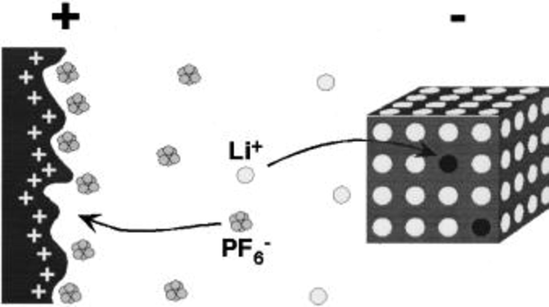
Figure 1. Simplified schematic of electrode reactions of an asymmetric hybrid cell.
The general concept of the nonaqueous electrolyte asymmetric hybrid cell, selection and performance of individual electrodes, and preliminary cell performance are presented. During the course of this study we introduce the use of a nanostructured  we have developed as a negative electrode material suitable for use in tandem with activated carbon positive electrodes. Finally, prototype bonded, flat plastic cells are introduced utilizing the asymmetric hybrid technology to demonstrate practical energy densities. In addition, the use of Ag is discussed as a quasi-reference electrode for fast, routine three-electrode characterization of such cells.
Experimental
Three-electrode cells
The use of a lithium metal reference electrode is the most accurate method for three-electrode electrochemical characterization in  electrolytes. However, Li reference electrodes are not easily reused and are somewhat tedious to fabricate on a routine basis. Quasi-reference Ag metal electrodes have been utilized in aqueous electrochemical cells; they are attractive because of ease of use and low electrical resistance. The disadvantage is a voltage drift in excess of 15 mV.14 Little published data exists with respect to their routine use in the characterization of nonaqueous electrochemical systems.
Three-electrode test cells used in these studies consisted of Teflon Swagelok™ bodies and seals with oxidation and reduction resistant stainless steel plungers. The third electrode consisted of a flattened metal wire inserted into the cell. The reference electrode was placed between two sheets of borosilicate glass fiber separator material (Fig. 2).
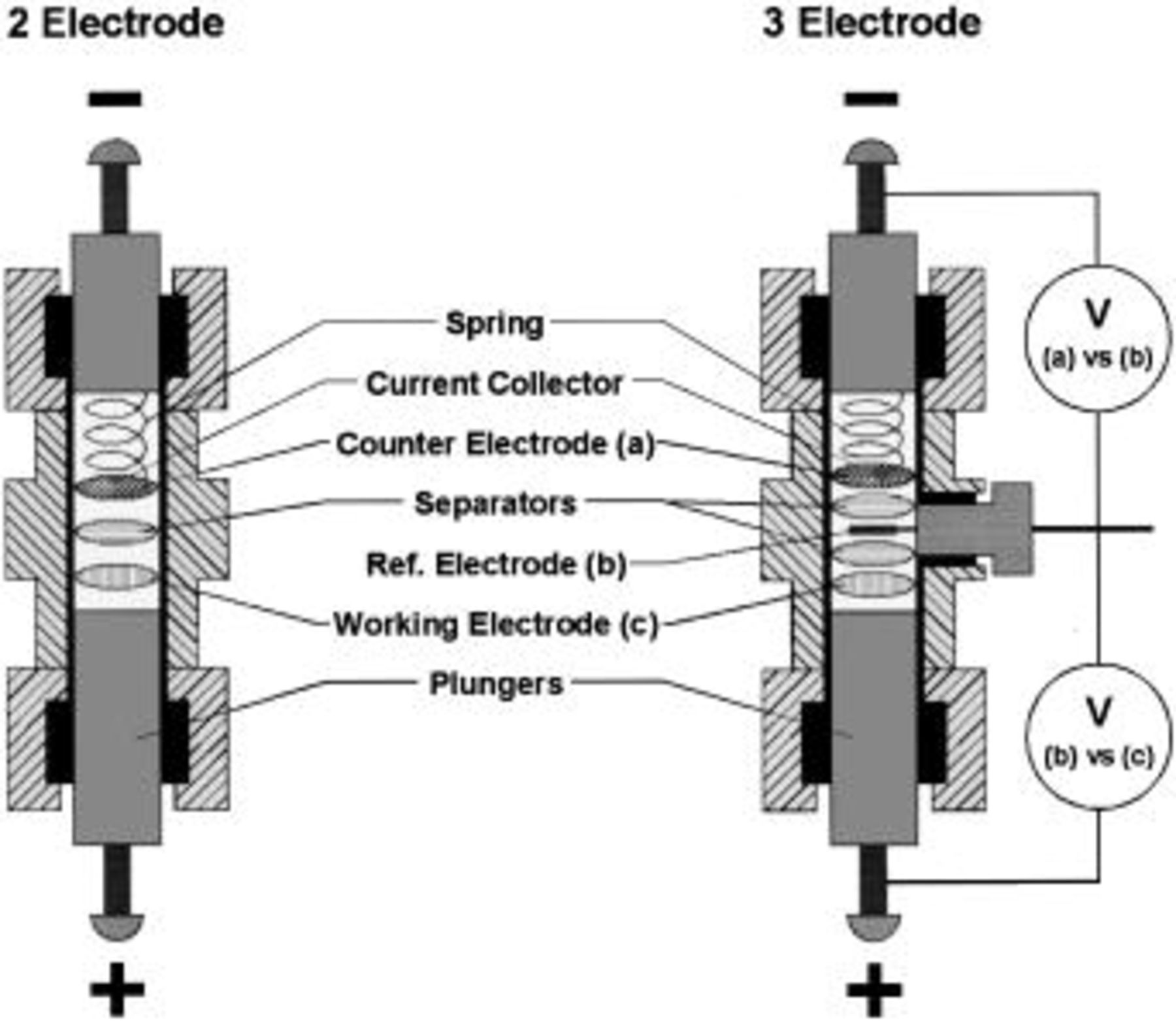
Figure 2. Schematic of a two- and three-electrode Teflon Swagelok™ cell.
Three-electrode characterization of the well-known Li-ion couple  vs. graphite was performed in order to calibrate and verify the accuracy of the Ag quasi-reference electrode. The Ag quasi-reference electrode and Li metal reference electrodes were incorporated into a three-electrode cell incorporating
  and mesocarbon microbeads (MCMB) 25-28 graphite as the positive and negative electrodes, respectively. The two-electrode results for both Li and Ag references are shown in Fig. 3a and b, respectively. The Li and Ag reference electrodes give virtually identical profiles. The three-electrode plot for the Li reference and Ag quasi-reference are also shown in Fig. 3a and b. Both the Ag quasi-reference electrode and the Li reference electrode enables clear identification of the solid electrolyte interface (SEI) formation on graphite at −2.2 and 0.8 V for the Ag quasi-reference and
  reference cell, respectively. Most important, little voltage drift during cycling was observed when the Ag alkali quasi-reference electrode was utilized. In short, excellent agreement was shown between the Ag quasi-reference and the true
  reference electrodes. Based on these and additional studies, we were able to calibrate the Ag quasi-reference electrode potential to be approximately 3.0 V vs.
  This is approximately equal to that of a standard hydrogen electrode (SHE). A number of alternative electrochemical couples were also characterized using the Ag quasi-reference electrode; all exhibited excellent stability for at least 1 month. During the course of this study it was noted that excessive electrolyte oxidation on the surface of activated carbon electrodes at high voltages and temperatures can result in potential drift. We believe that the drift was due to the formation of oxidation byproducts that altered the surface chemistry of the Ag electrode.
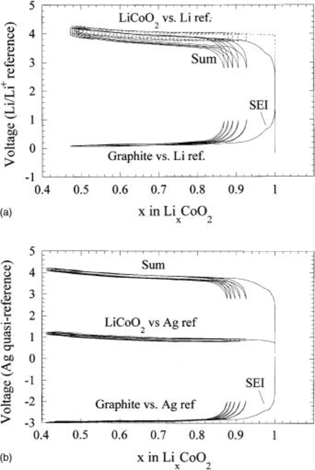
Figure 3. Two- and three-electrode voltage profiles of a graphite/ cell utilizing a (a, top) Li metal reference and (b, bottom) Ag quasi-reference electrode.
General
High surface area activated carbons were obtained either in their powder form from natural precursors (Norit) or fabric based on a synthetic polacrylonitrile (PAN) precursor (Kothmex, Taiwan Carbon). Activated carbons had surface areas ranging from 700 to 2000 m2/g. MCMB 25-28 (Osaka Gas) and expanded graphite (Superior Graphite) were used as anion intercalation hosts. Nanostructured  was fabricated by high-temperature solid-state reaction of nanocrystalline
  and
and  Additional details regarding the fabrication and performance of these materials will be published elsewhere.
All Swagelok coin cell electrodes were made by way of the Telcordia plastic electrode technology process.15 65% active material was mixed with 6.5% carbon black (MMM Super P), 10% poly(vinylidene fluoride-co-hexafluoropropylene) binder (Elf Atochem, Kynar Flex 2801), and 18% dibutyl phthalate plasticizer in acetone. The mixture was cast and dried at 22°C for 0.5 h. Afterward, disks were punched from the freestanding tape. The disks were then placed in ether to extract the plasticizer. The electrolyte was a 1 M  in 2:1 volume ratio of ethylene carbonate (EC):dimethyl carbonate (DMC). Electrochemical cycling was performed either on a MacPile (Biologic, France) or Maccor galvanostat. All cell fabrication was performed in a −80°C dewpoint, He-filled glove box. Stainless steel coin cells (NRC), utilizing borosilicate glass fiber mat separator, were used for two-electrode cell characterization.
All electrode material characterization performed at high rates in coin cell and Swagelok was done in such configurations that the amount of active material in the electrode did not result in cell current densities in excess of 10 mA/cm2. This was to ensure that system restraints (unoptimized electrolyte, etc.) did not influence the electrochemical characterization of the electrode materials. Relatively slow (C/2) discharge rates were utilized only to extend residence time during long-term cycling evaluation to gather more realistic data with respect to cell lifetime. Discharge rate utilization exceeded charge rate utilization in all asymmetric hybrid examples and therefore were not the subject of optimization.
Results
Asymmetric hybrid.—Positive electrode selection
In order to achieve high energy density, the positive electrode of the asymmetric cell should exhibit high reversible capacity with the anion of the electrolyte at voltages in excess of 0.5 V (SHE). The electrode must also be capable of extremely fast electrochemical reaction with the anion and exhibit exceptional cycle life. Few materials presently exist which can satisfy these requirements.
A number of organic redox materials exist which may be utilized for their pseudocapacitive p-doping behavior. Polypyrrole and polythiophenes exhibit promising behavior,16 17 however, we elected not to include them in this initial study because of practical limitations of these materials (cost, stability, cycle life). Carbon materials offer a wide degree of electrochemical activity with anions. Graphite and coke-based compounds are known to electrochemically intercalate anion species at high potential and are used as a positive electrode in C-C intercalation cells.18 19 These are attractive for use in C-C cells because of their excellent specific capacity. Activated carbons have surface areas which exceed 1500 m2/g and have an exceptional propensity for anion double-layer adsorption as demonstrated in nonaqueous EDLCs. The fundamental chemical similarity and practicality of both the capacitive and intercalation carbons made these interesting to compare from an electrochemical point of view.
Three Li anode cells were fabricated utilizing a MCMB 25-28 graphite, expanded graphite, and activated carbon (PAN based) as the positive electrode and 1 M  EC:DMC as the electrolyte. The voltage profiles of these cells for one complete charge-discharge cycle are shown in Fig. 4. Both graphites exhibit the onset of intercalation with the
  anion at 4.5 V, however, the expanded graphite has a larger capacity for intercalation. This is most likely due to its smaller particle size and a smaller
  of 350 Å compared to 650 Å for the MCMB 25-28. The intercalation and deintercalation proceeds on plateaus which is suggestive of an ordering reaction among the planes with respect to
  intercalation.20 Further intercalation of
  could be performed, but higher voltages challenged the electrochemical stability window of the electrolytes when the voltage exceeded 5.15 V. The activated carbon exhibited significant capacity with respect to anion double-layer formation, as did the intercalated graphites. As expected for the capacitive adsorption process, the voltage increased linearly with capacity. The slight deviation from linear behavior at the end of charge is the result of electrolyte oxidation on the high surface area activated carbon, an issue which is investigated further on in this paper. The anion intercalation and double-layer adsorption processes resulted in approximately identical capacities within the specified voltage range. Rate capabilities were also characterized for the three carbons. Figure 5 shows the rate capability of the adsorption process is far superior to that of the intercalation process for any of the graphites. This is expected, as no bulk diffusion within the particle is required for the nonfaradaic process. Among the graphites, the expanded graphite exhibited much improved rate capability. Based on good capacity and excellent rate capability, activated carbon was chosen as the preferred positive electrode material for this study.
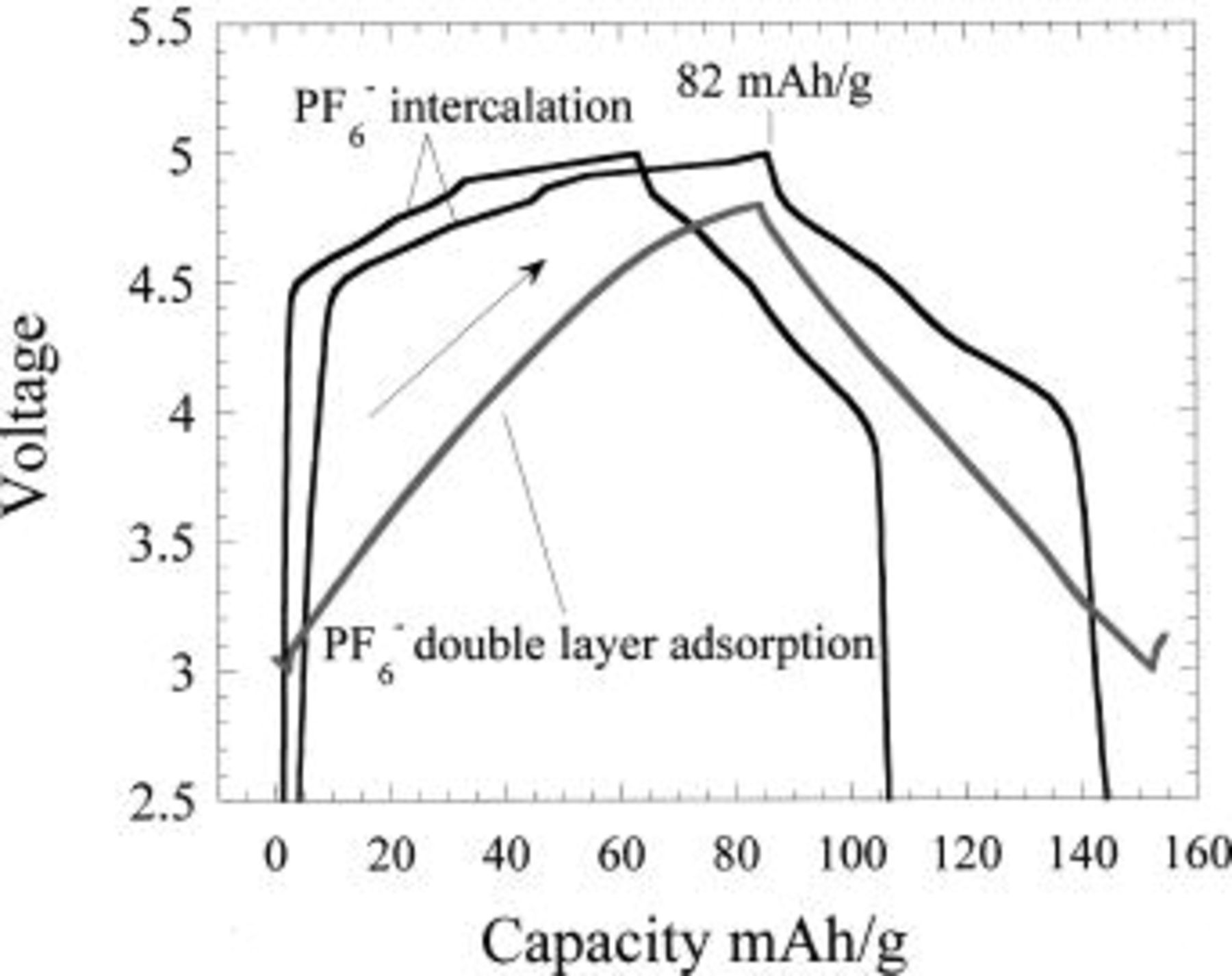
Figure 4. Charge discharge reactions of MCMB graphite (upper), expanded graphite (middle), and activated carbon (lower) in  EC/DMC electrolyte vs. Li metal.
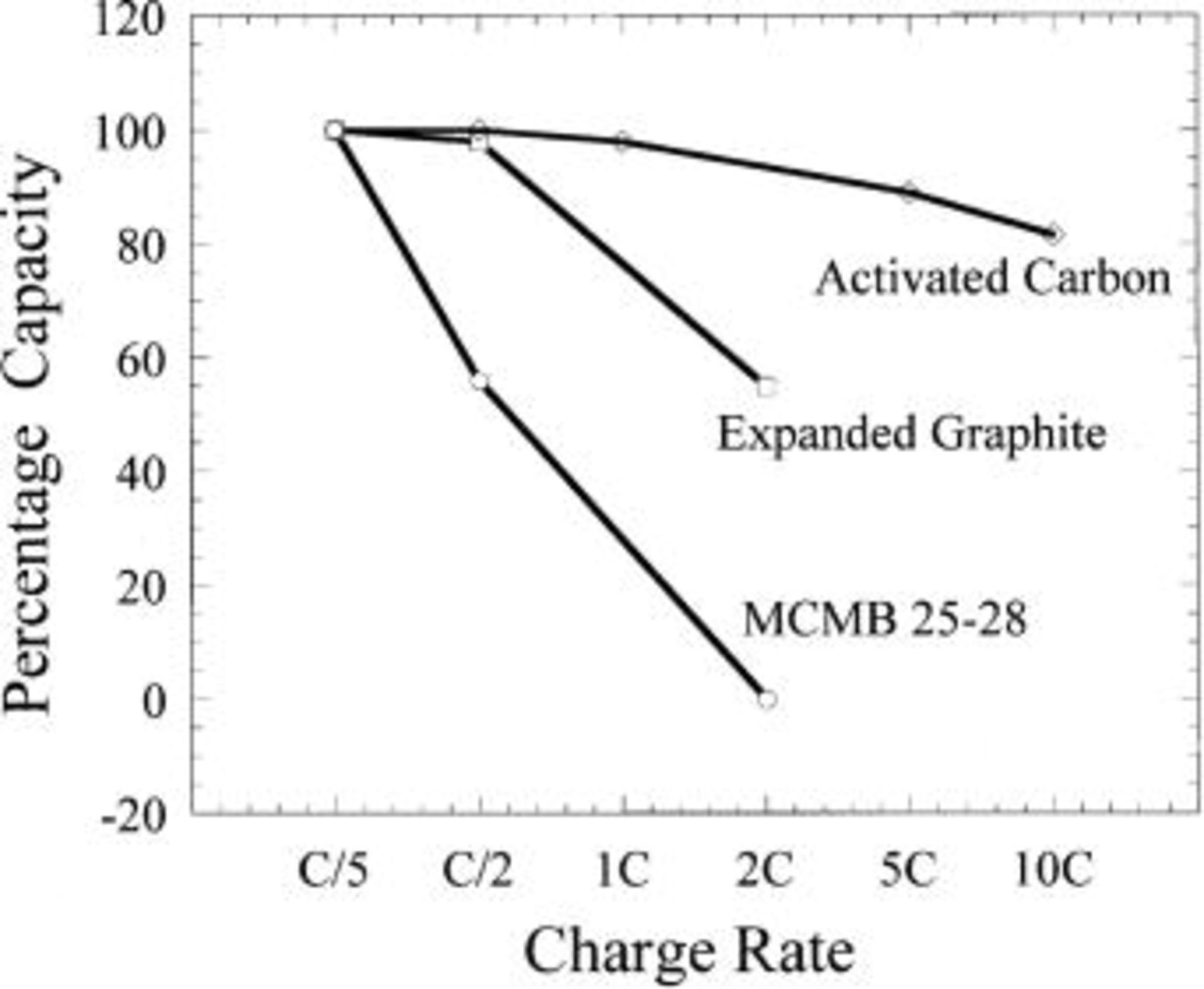
Figure 5. Charge rate comparison between  intercalation reaction in graphites and adsorption on activated carbon.
We are concerned with characterization and improvement of the specific capacity of the activated carbon with respect to the anion, therefore, we characterized the specific capacities of activated carbons of a wide range of surface areas. In order to isolate the capacitance or the capacity over a defined voltage range for the anion, we tested the electrodes at a relatively slow rate of 1C in an asymmetric configuration vs. Li metal. As the cell is charged,  is reduced at the Li metal negative electrode and the
  anion is adsorbed into a double layer on the positive electrode. Figure 6 shows a representative plot of the capacity of the activated carbon for an activated carbon fabricated from a pyrolized activated PAN. Capacities (mAh/g) of these activated carbons can be converted to their capacitance (F/g) by the following formula 3
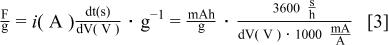
This relation is only valid if the voltage vs. time relation is a linear, nonfaradaic function. Based on this expression the calculated specific capacity and capacitance is shown in Table I for all carbons tested. Based on Eq. 1, the capacitance of the anion on activated carbon should be a direct function of the carbon surface area. The relationship between the capacitance of the activated carbons and their surface area is shown in Fig. 7. As expected, a close relationship is observed. Based on the relatively large capacities of 45 mAh/g over a voltage range of 0-1.3 V (SHE), 3-4.3 V  sample G, a synthetic PAN-based activated carbon, was utilized as a positive electrode for the initial asymmetric hybrid cell constructions.
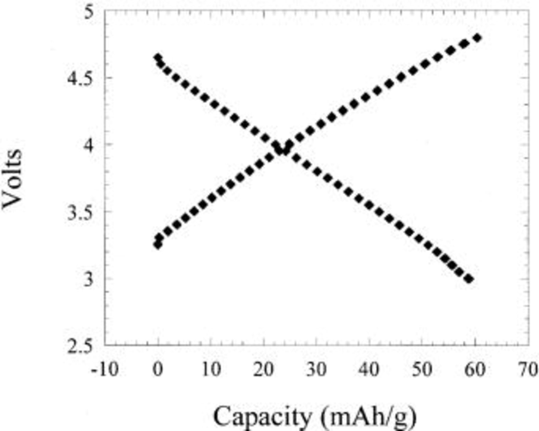
Figure 6. Charge-discharge plots showing  adsorption and desorption specific capacity of a PAN-based activated carbon electrode vs. Li metal.
Table I.
| Anion double-layer capacitance and specific capacity values for activated carbons of various Brunauer-Emmett-Teller (BET) surface areas. Specfic capacity values were calculated from 3-4.3 V. | |||
|---|---|---|---|
| Sample | Surface area (m2/g) | Capacity 3-4.3 V(m Ah/g) | Capacitance (F/g) |
| A | 884 | 18 | 64.8 |
| B | 1200 | 28 | 100.8 |
| C | 920 | 36 | 93.6 |
| D | 800 | 20 | 72 |
| E | 1400 | 28 | 100.8 |
| F | 2000 | 36 | 129.6 |
| G | 2400 | 46 | 165.6 |
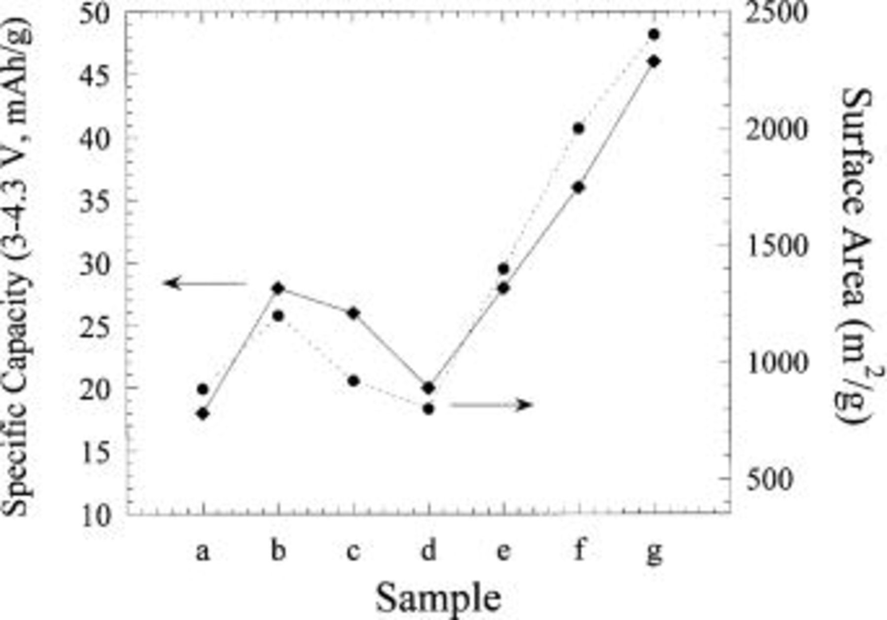
Figure 7. Specific capacity of a  anion double-layer reaction and specific surface areas measured for various activated carbons.
Negative electrode
Besides low reduction potential with respect to SHE and high specific capacity, the faradaic negative electrode intercalation compound utilized in the asymmetric hybrid cell must complement the performance attributes of the nonfaradaic activated carbon positive electrode. These attributes include exceptional cycle life and excellent rate capability.
A number of intercalation compounds exist which intercalate  at voltages below −1 V SHE. These include a wide class of materials such as oxides, nitrides, sulfides, alloys, phosphates, and carbonaceous materials which have been characterized for use as negative electrodes in Li-ion batteries. Carbonaceous intercalation materials, such as graphites, hard carbons, and coke, are highly desirable from an energy density point of view as these materials intercalate
  at voltages close to −3 V SHE. However, as Fig. 8 shows, the low voltage and subsequent proximity to the plating potential of Li is not desirable because Li plating may be induced with undervoltage during fast charge protocols.
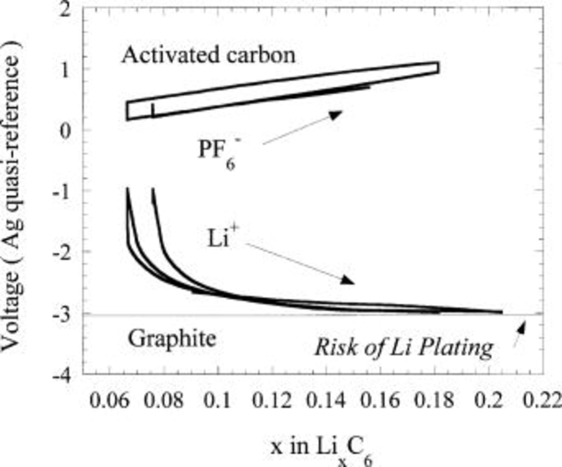
Figure 8. Three-electrode voltage plot of an activated carbon/ EC:DMC/Li metal electrochemical cell.
The most demanding requirement demanded by the asymmetric hybrid with activated positive electrode is cycling stability >103 cycles. Almost all intercalation compounds undergo some degree of expansion or contraction upon intercalation. Most intercalation compounds are ceramic materials exhibiting a high Young's modulus. Crystallographic isotropic or even worse, anisotropic expansion and contraction will lead to an extensive amount of electromechanical grinding at incoherent grain or domain boundaries. This leads to electrical disconnection of the particle and resulting capacity loss. The failure scales with material modulus, particle size, anisotropy of expansion and contraction, and finally the degree of expansion and contraction.
All the requirements that have been set forth for the negative electrode can, for the most part, be met by the intercalation compound 
 exhibits a two-phase lithium intercalation reaction at approximately 1.5 V

The two-phase reaction results in a very flat voltage plateau at approximately 1.5 V  21
22
23
24
25
26 (Fig. 9) which can offset the steep, linear, nonfaradaic profile of the activated carbon positive electrode of the asymmetric cell.
21
22
23
24
25
26 (Fig. 9) which can offset the steep, linear, nonfaradaic profile of the activated carbon positive electrode of the asymmetric cell.  is one of the few lithium intercalation compounds that exhibit little appreciable expansion or contraction during the lithium insertion-reinsertion process (Ohzuku et al.).27 The 1.5 V
  voltage of the lithium insertion process is low enough vs. the 3-4 V
  nonfaradaic positive electrode for the energy density to remain high; it also provides a safety window of 1.5 V against electrochemical plating of lithium during extremely fast lithiation. In order to obtain appreciable performance at intercalation rates requiring full intercalation of lithium ions within 6 min (10C), we found it was necessary to develop a nanostructured
  material. Comparison of the nanostructured
  with conventional
  made through solid-state synthesis is shown in Fig. 10. The nanostructured material offered at least a 30% improvement in lithiation (asymmetric hybrid charge) rate capability. Details of the nanostructured
  will be published elsewhere. Figure 11 shows the cycle life of the nanostructured
  vs. a Li metal negative electrode cycled at a rate of C/2. Less than 2% capacity loss occurred after 750 cycles, the majority of it due to failure of the Li electrode. This is the best cycling stability that we have observed published for any intercalation material (non-thin film), including
  The good cycle life of the
  complements the exceptional cycle life of the nonfaradaic activated carbon positive electrode.
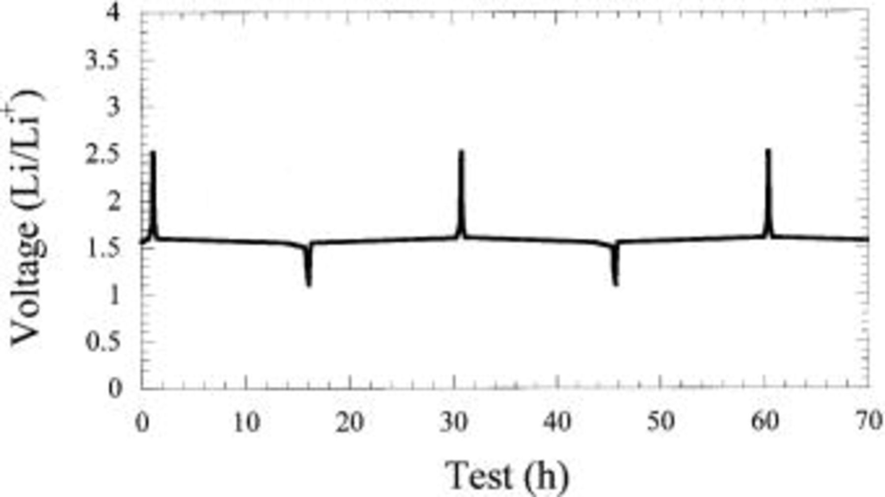
Figure 9. Charge-discharge profile of  vs. Li.
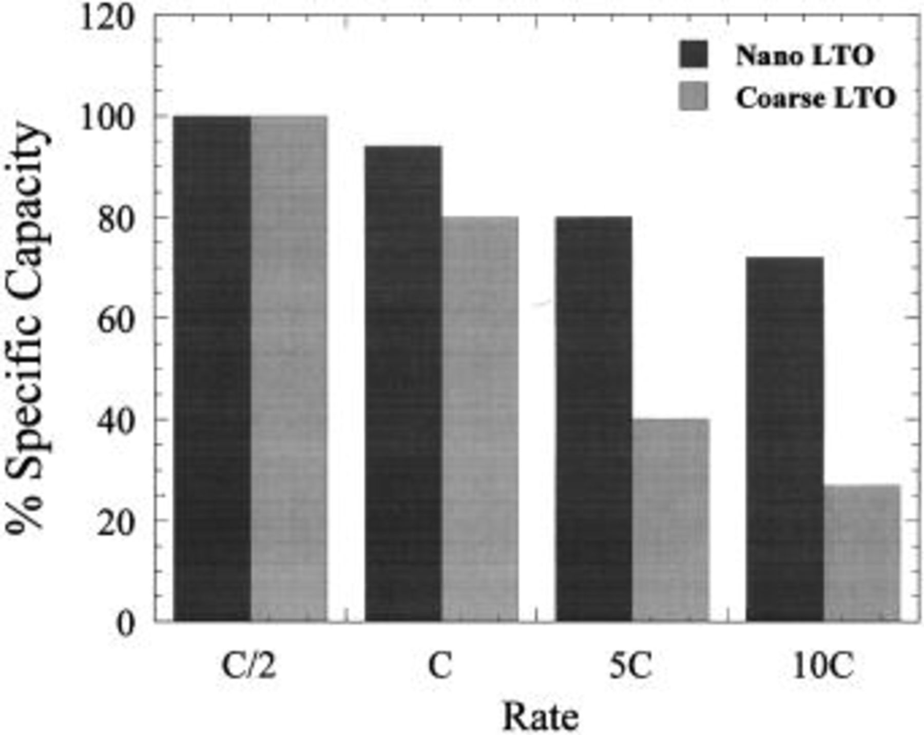
Figure 10. Specific capacity as a function of lithiation rate for a nano and coarse  vs. Li metal.
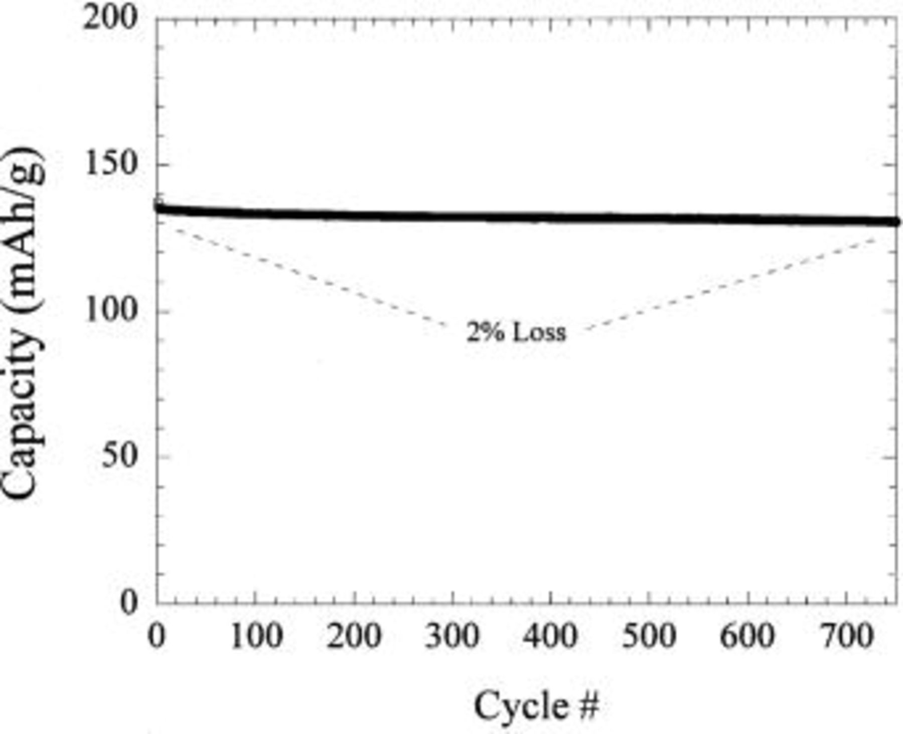
Figure 11. Cycle life of a  cell cycled at C/2 charge and discharge cycled between 1.2 and 2.5 V.
Asymmetric hybrid cell
A three-electrode cell was fabricated utilizing the activated carbon composite material as the positive electrode and the  material as the negative electrode. The activated carbon positive electrode and
  negative electrode were based on an active weight ratio of 4:1, respectively. The balancing ratio was calculated using the 35 mAh/g specific capacity for the activated carbon and 140 mAh/g specific capacity for the
  measured vs. Li metal. This ratio ensures full lithiation of the
  negative electrode upon charge. An Ag wire was used as a quasi-reference electrode. 1 M
  in 2 EC:DMC (vol:vol) was used as the electrolyte. Figure 12 is a plot of the individual electrode profiles along with a composite voltage profile during cell cycling. The
  electrode shows a flat two-phase intercalation to full capacity at −1.4 V vs. Ag quasi-reference. This is identical to the two-phase lithium intercalation reaction observed at approximately 1.5 V vs.
  confirming intercalation. Simultaneous with the intercalation reaction at the negative electrode, a
  double layer forms on the surface of the positive electrode carbon. The electrode reaction reveals the typical linear voltage increase one would expect for a nonfaradaic reaction. The composite voltage profile of the
  vs. C cell reveals a gradually sloping profile between 1.5 and 2.5 V (Fig. 13) compared with the sharply sloped carbon-carbon nonaqueous EDLC.
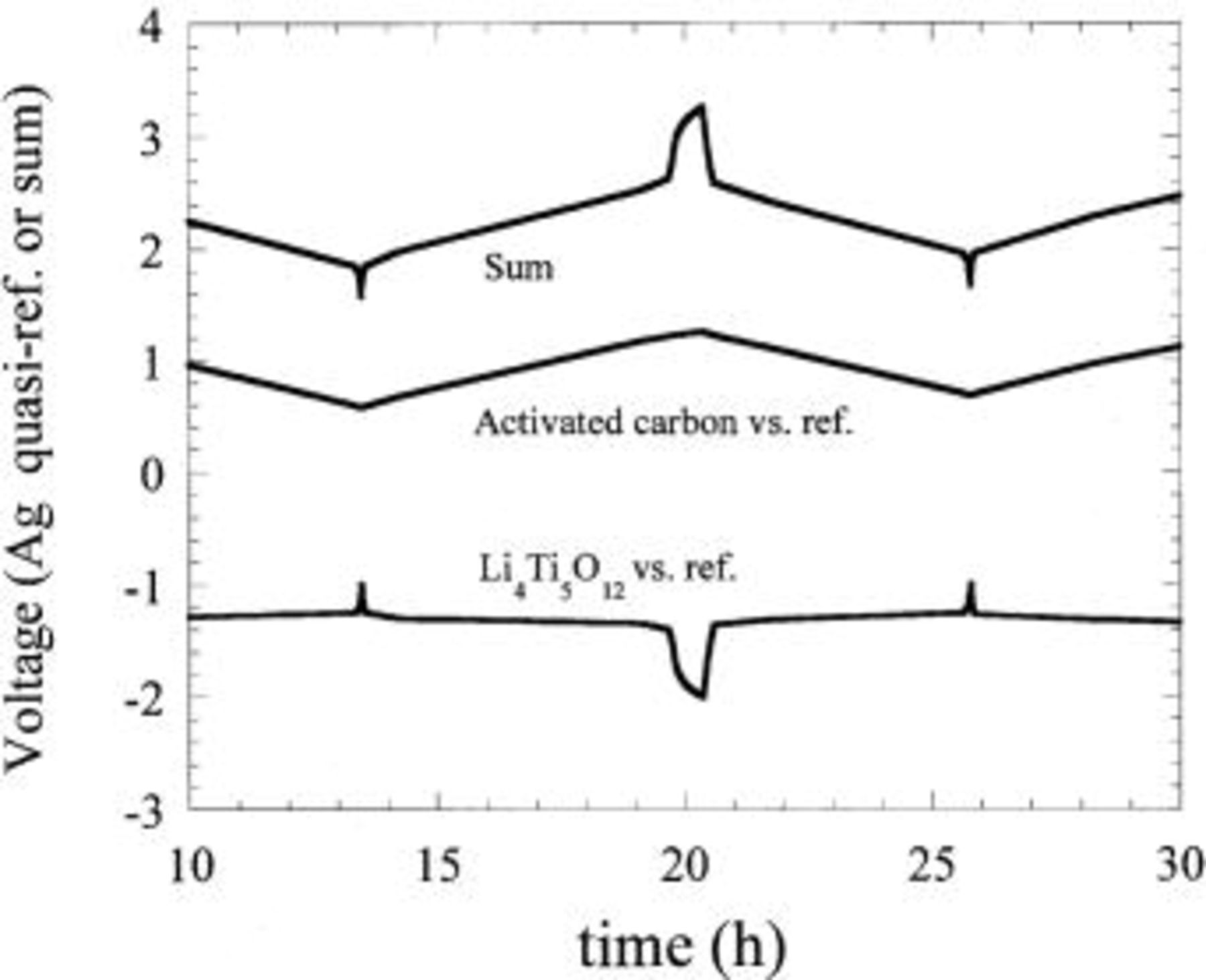
Figure 12. Three-electrode measurement of an asymmetric hybrid cell utilizing an activated carbon positive electrode and  negative electrode in
  EC/DMC electrolyte.
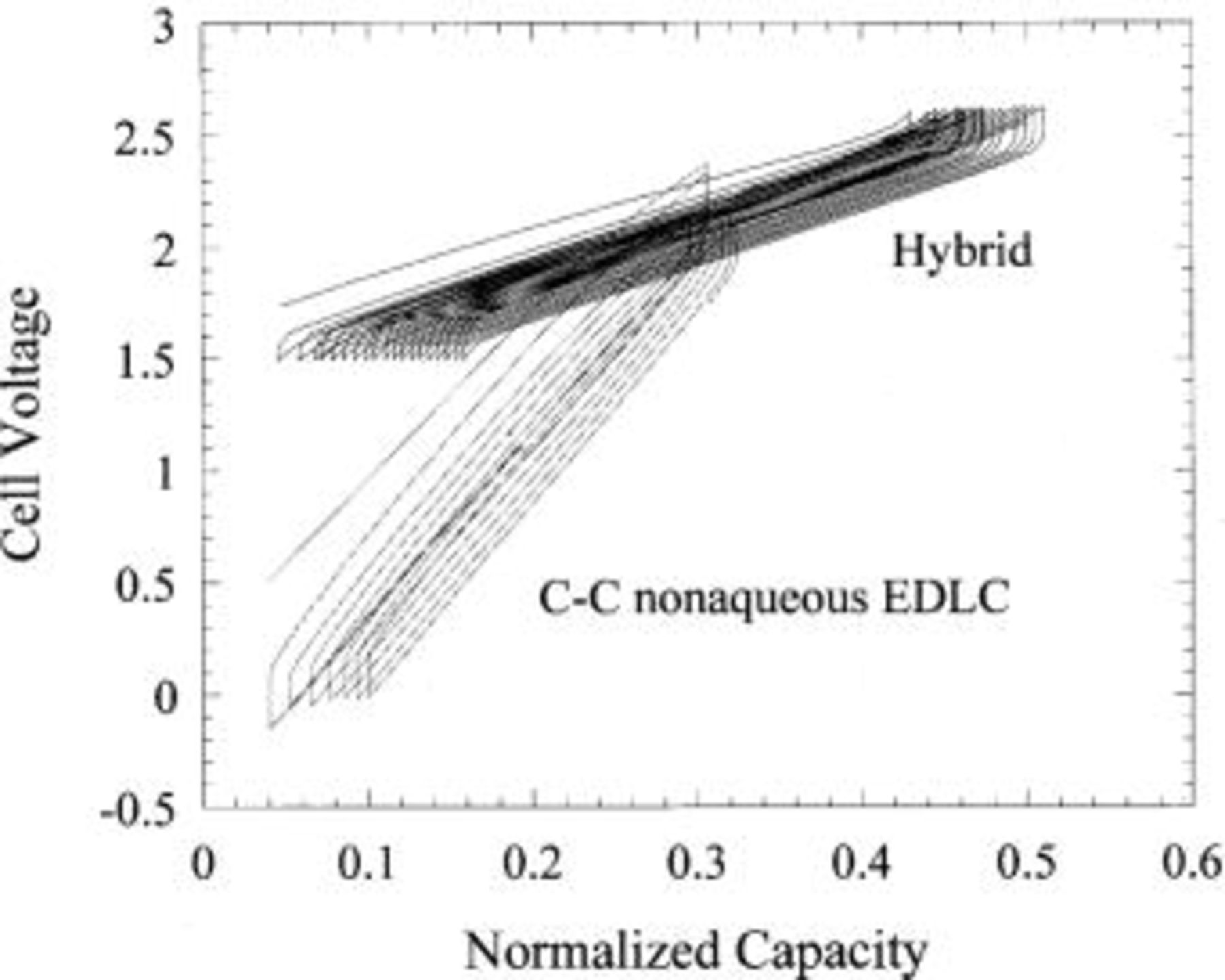
Figure 13. Charge-discharge voltage profiles of an asymmetric hybrid vs. a carbon-carbon nonaqueous EDLC. Capacity is normalized.
Figure 14a shows the cycling of the hybrid configuration. 0% capacity loss was recorded after 200 cycles of 8C charge and C/2 discharge, fast charging of 10C (6 min) results in 92% utilization with similar cycling efficiency. The excellent cycling stability of the  (Fig. 11) complements the intrinsic cycling stability of the nonfaradaic, nonintercalation activated carbon. Extended cycling for this couple is shown in Fig. 14b, little capacity loss is exhibited after 800 cycles at 10C charge. Utilizing an extreme cycling condition of 10C charge and 10C discharge with no relaxation between cycles the cell demonstrated 4500 cycles with less than 18% capacity loss (Fig. 15).
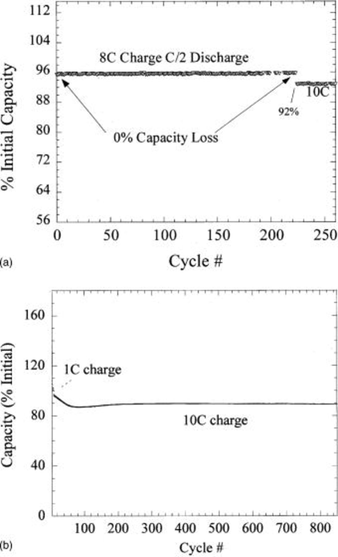
Figure 14. (a top) Cycle life of an asymmetric hybrid utilizing activated carbon positive electrode and  negative electrode. Charge rate is 8 and 10C, discharge rate is C/2, cell is cycled between 1.5 and 3.2 V. (b, bottom) Extended cycle life of a similarly constructed asymmetric hybrid cell.
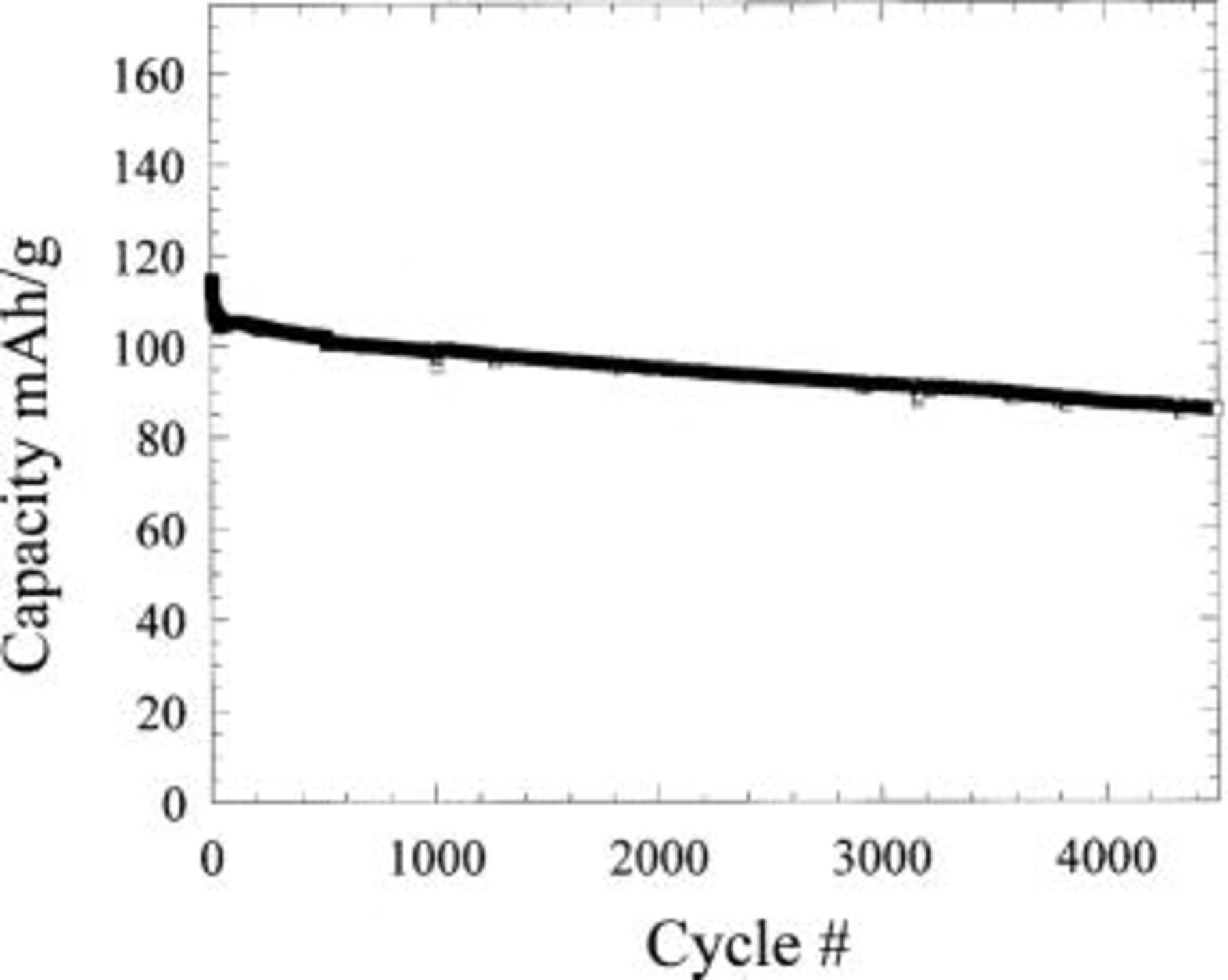
Figure 15. Cycle life for an activated carbon/ cell cycled at 10C charge, 10C discharge with no relaxation between cycles.
Electrolyte oxidation
The use of high-surface area carbons at voltages in excess of 1 V vs. SHE (4 V vs.  ) challenges the electrochemical stability of the nonaqueous electrolyte. The energy density of the asymmetric cell scales with the maximum usable voltage of the activated carbon positive electrode. This is the result of two factors: (i) unlike faradaic intercalation compounds, the capacity of the nonfaradaic activated carbon electrode scales linearly with voltage, and (ii) a higher cutoff voltage will result in a higher average voltage for the cell, therefore, increasing energy density. In light of these benefits, an understanding of the failure mechanisms involved with the use of higher potentials at the activated carbon positive electrode is desirable.
It is has been shown that relatively low surface area carbons undergo oxidative side reactions in nonaqueous lithium electrolytes.28 Instead of the 20-200 m2/g carbon blacks characterized in these previous studies, the positive electrode material of the asymmetric cell has a surface area ranging from 800 to 2000 m2/g. At high potentials, we have observed a departure from the typical linear voltage, nonfaradaic response that we would expect from a pure double-layer adsorption reaction at the activated carbon positive electrode. Also, our elevated temperature study revealed that irreversible capacity loss after a week at 55°C was 0%, but our reversible capacity loss approached 100%. This self-discharge behavior is in sharp contrast to room temperature results which indicated a reversible capacity loss of approximately 8% per month. In light of these results we have embarked on an initial investigation of the voltage-dependent, room and elevated temperature properties of these materials using cyclic voltammetry.
Two asymmetric hybrid cells utilizing PAN-based activated carbon fabric vs. Li metal were fabricated and cycled at a rate of 20 mV/0.125 h. Both cells were cycled to high potentials, the first to 4.5 V and the second from 4.6 to 4.8 V. The voltammetry results for the 4.5 V cell are shown in Fig. 16a. The data shows considerable anodic oxidation at voltages >4.4 V, however, the degree of oxidation as a function of cycle number is difficult to decipher. Figure 16b shows the plot of the identical cell cycled from 3 to 4.5 V showing current as a function of time. This plot style accentuates the peak current as a function of cycle number. All peak currents occurred at the high voltage region of the anodic scan. Figure 16b shows that the initial peak oxidative current is high, but rapidly decreases as a function of cycle number. When the cell is placed at 55°C, the peak current abruptly increases and then quickly subsides to a constant value, which is less than 1 mA above the cathodic current. The second cell of Fig. 17 was initially cycled to 4.6 V, then raised to 4.8 V after a few cycles. The initial current increases systematically with an increase in the upper cutoff voltage. In both voltage regimes the peak current is shown to rapidly fade similar to the cell of Fig. 16b. Finally, when the cell cycled to 4.8 V was placed at 55°C, a large anodic current peaking at 8.5 mA was observed, a value which continually decreased to a value approaching 3 mA after 100 cycles. This data suggests a substantial degree of electrolyte oxidation is occurring at the carbon surface when the high surface area carbon electrode is exposed to high potentials and/or elevated temperature. However, this oxidative current is found to decrease rapidly as a function of cycle number, suggesting carbon passivation which prevents further electrolyte oxidation. The effect of high potentials and elevated temperatures on capacity is surprisingly minimal, after 70 cycles to 4.8 V at 55°C, less than 2% capacity loss was measured. However, we have not yet evaluated the effect of temperatures and upper cutoff voltages on the rate performance. Based on these results, we expect reversible self-discharge can be decreased significantly with a lower upper voltage cutoff, proper activated carbon surface pretreatments, improved electrolytes, and the possible replacement with organoredox positive electrodes.
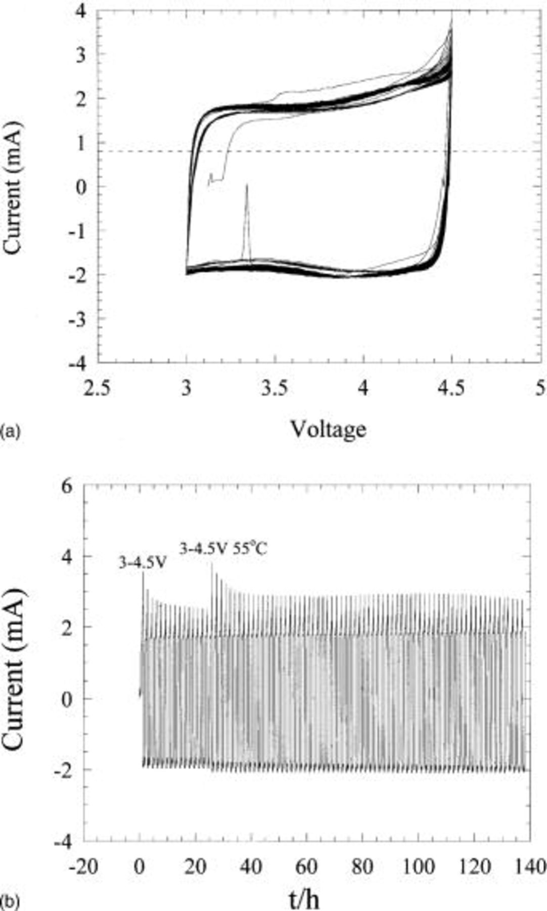
Figure 16. (a) Cyclic voltammetry of activated carbon vs. Li metal at 20 mV/0.125 h. (b) Current plotted as function of time for cyclic voltammetry results of (a).
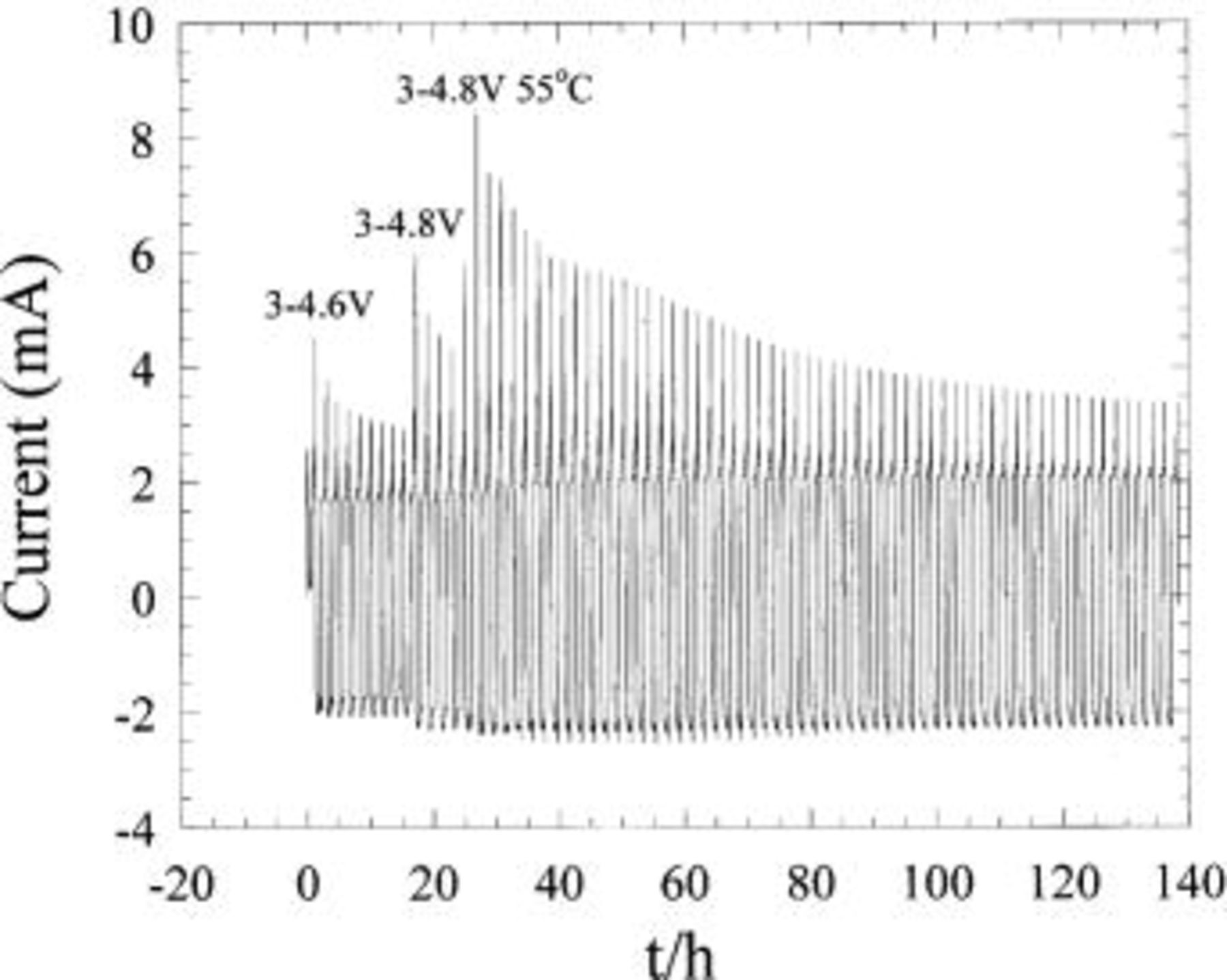
Figure 17. Current plotted as function of time for an activated carbon vs. Li metal cell cycled at 20 mV/0.125 h.
Prototype bonded plastic asymmetric hybrid cells
Plastic asymmetric hybrid cells were fabricated in a similar fashion to the Telcordia plastic Li-ion technology cells14 in order to calculate the energy density of this device in a packaged prototype cell. Both electrodes were fabricated by mixing the active material, poly(vinylidene fluoride-co-hexafluoropropylene) binder, propylene carbonate plasticizer, and conductive carbon black in acetone. For the  electrode, active loadings were 65 wt % and tape thickness was approximately 200 μm. The positive electrode consisted of A-supra activated carbon (Norit). The positive electrode active material weight ratio was 4:1 with respect to the
  negative electrode. The slurries were cast and dried in ambient for 1 h. A surface-treated 25 μm separator (Celgard) was used as the separator material. The electrodes, aluminum grid current collectors, and separators were heat laminated into a bicell configuration which is essentially two asymmetric hybrid cells sharing a common current collector. The plasticizer retained the porosity during lamination. The propylene carbonate plasticizer contained in the electrodes of the bonded cell was then removed by extraction in ether. The cells were packaged in a laminate packaging material consisting of a thermoplastic sealing layer and a thin aluminum hermetic layer. The cells were dried and activated in a −80°C dew point He-filled glove box. The cells were then activated using 1.5 M
  acetonitrile electrolyte. We have found this electrolyte to result in very high ionic conductivity of 38 mS/cm at 22°C.
Figure 18 shows the voltage profile of the first few cycles of the plastic asymmetric hybrid device. Energy density of 18 Wh/kg was measured for a 40 mAh  packaged device. Preliminary cycling at C/2, C, 5C, and 10C charge (33 mA/cm2), C/2 discharge is shown in Fig. 19. 10C rate capability of the plastic prototype cells was observed to be consistent with liquid coin cells. Excellent capacity retention even at 50C discharge is noted (Fig. 20), maintaining approximately 75% of the full intercalation capacity of the nanostructured
  Long-term cycle life of the preliminary prototype packaged cells is shown in Fig. 21 compared with similarly constructed nonaqueous plastic nonaqueous EDLC technology (activated carbon/tetraethylammoniumtetrafluoroborate acetonitrile/activated carbon) and plastic Li-ion technology (
 /graphite). The asymmetric hybrid chemistry shows a cycle life which parallels that observed for nonaqueous EDLC technology and is much improved over that of Li ion. Energy density of 25 Wh/kg was measured for a 400 mAh plastic asymmetric hybrid cell, 500-700% greater than that of packaged nonaqueous EDLC technology.
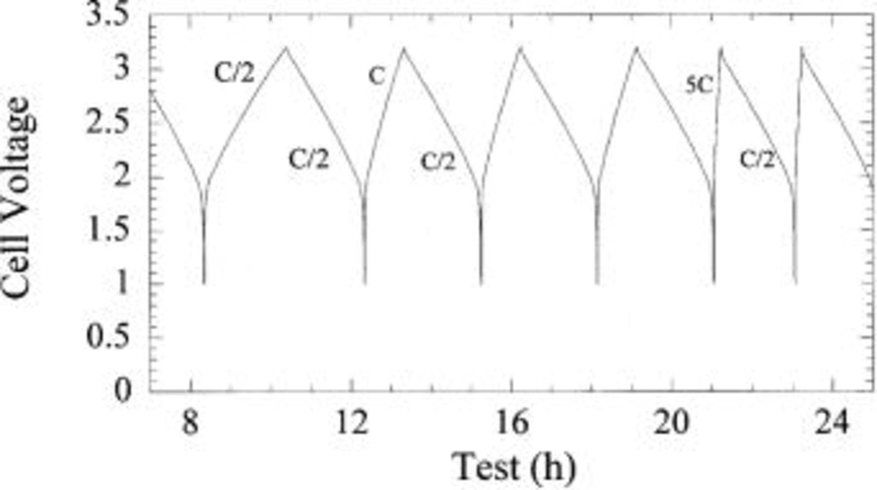
Figure 18. Voltage profile of plastic asymmetric hybrid cell.
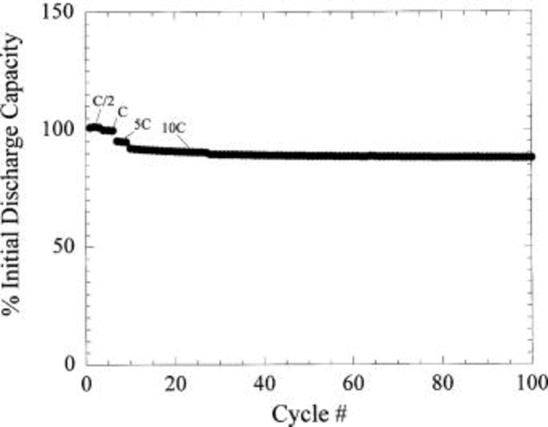
Figure 19. Cycle life of plastic asymmetric hybrid cell (see text for details).
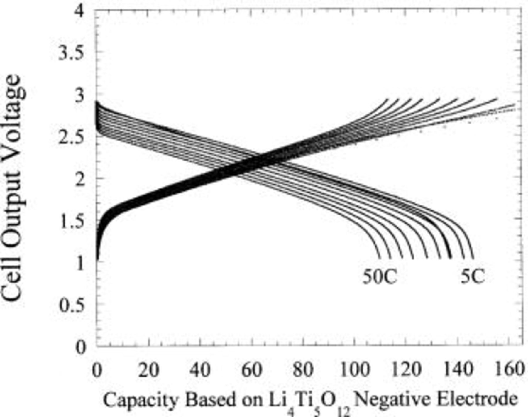
Figure 20. Discharge profile as function of rate for plastic activated carbon/ cell. Specific capacity (mAh/g) of
  is shown.
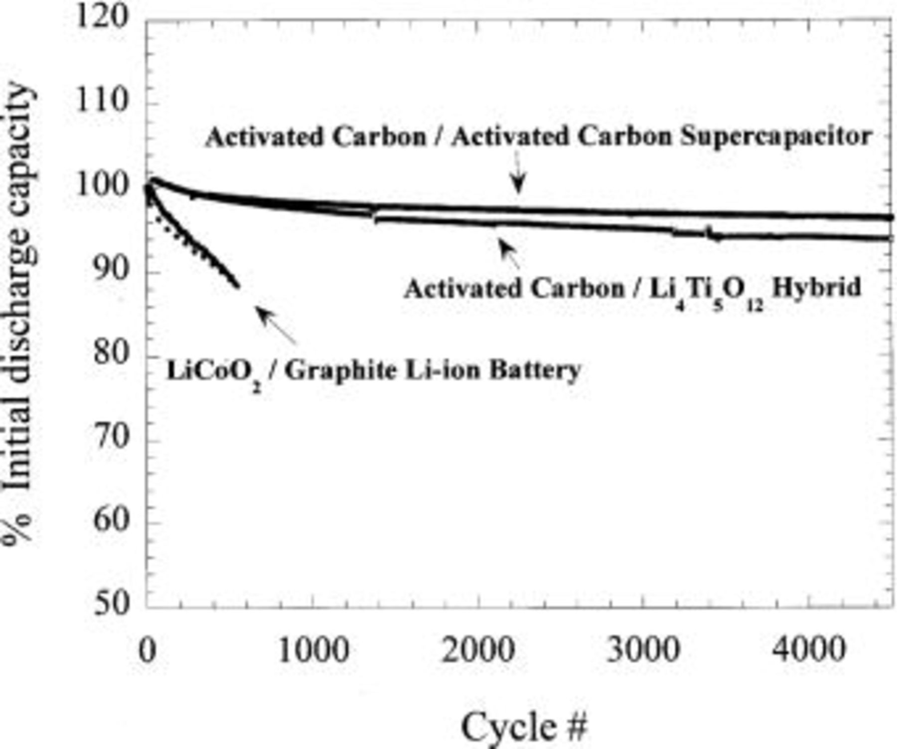
Figure 21. Comparison of capacity vs. cycle number for plastic Li-ion technology, plastic asymmetric hybrid technology, and plastic nonaqueous EDLC technology.
Discussion
Double-layer adsorption of the anion by the positive electrode and simultaneous intercalation of  into the negative electrode requires all of the ionic species to be localized in the electrolyte. As required in most electrochemical energy storage technologies, the asymmetric hybrid cell must be balanced for peak efficiency with respect to the capacity of the positive and negative electrodes. However, in addition, the "capacity," or ionic content, of the electrolyte solution must also be balanced. This is a similar situation faced by carbon-carbon intercalation batteries.29 This issue raises the importance of maximization of the salt solubility and also the selection of salts with minimal molecular weight. The specific capacity of lithium salts ranges from 176 mAh/g for
  172 mAh/g for
  252 mAh/g for
  to 286 mAh/g for
  Therefore changing the salt from
  to
to  will reduce the required weight of salt by 63%.
Because of the reversible consumption of the electrolyte salt in the electrolyte solution, the molarity of the electrolyte salt solution will undergo wide swings with each charge and discharge. Each mole of electrolyte is equivalent to 26.8 Ah in capacity. Therefore, in the development of such fast charge asymmetric cells, one must be conscious of the change in conductivity of the electrolyte as a function of salt concentration. The conductivity of this system is a relatively strong function of the electrolyte, therefore the molarity of the solution should be optimized so that the change in the conductivity is minimized during cycling of the cell.
Compared with Li-ion battery chemistry, the electrolyte has an important difference in the asymmetric hybrid. In Li-ion batteries salt concentration polarization is a limiting factor to the rate capability of the electrolyte system.30 During fast discharge in Li-ion battery chemistry,  ions are deintercalated from the graphite negative electrode. Simultaneously,
  ions are intercalated into the positive electrode. This results in a localized excess of positive charge (
 ions) and negative charge (
 electrolyte anions) at the two electrodes, respectively. The faster diffusing
  anions diffuse from the positive electrode to the negative electrode to equilibrate charge. This in turn leads to a depletion of electrolyte salt at the positive electrode and excess salt at the negative electrode. During fast discharge the process works in reverse, and is as equally inhibiting. In contrast, the asymmetric hybrid has a symmetric driving force for the
  ions and
  to the opposing electrodes which will reduce concentration gradients and which may result in a positive effect on the fundamental current density capability of the electrolyte system. This is especially apparent during fast discharge as both anions and cations are introduced into the electrolyte rather than depleted at one electrode.
A nonaqueous EDLC utilizes two electrodes having a capacity of 30-40 mAh/g. The basic  hybrid system utilizes a positive electrode with a specific capacity of 30-40 mAh/g and a negative electrode capacity of 120-160 mAh/g (depending on preparation conditions). The increase in the gravimetric and volumetric energy densities of the negative electrode results in a significant increase of the overall energy density of the cell. Under optimized conditions, the usable capacity of a C-C nonaqueous EDLC is between 0 and 3 V (average
  ) (Fig. 22). Due to the flat two-phase
  intercalation plateau of the
  at −1.5 V SHE which effectively "pins"the negative electrode voltage, the useable capacity of the hybrid cell (of Fig. 22) is between 1.5 and 3 V (average
  ). The average voltage increase raises the cell energy density significantly without requiring an increase in current density for a fixed C rate.
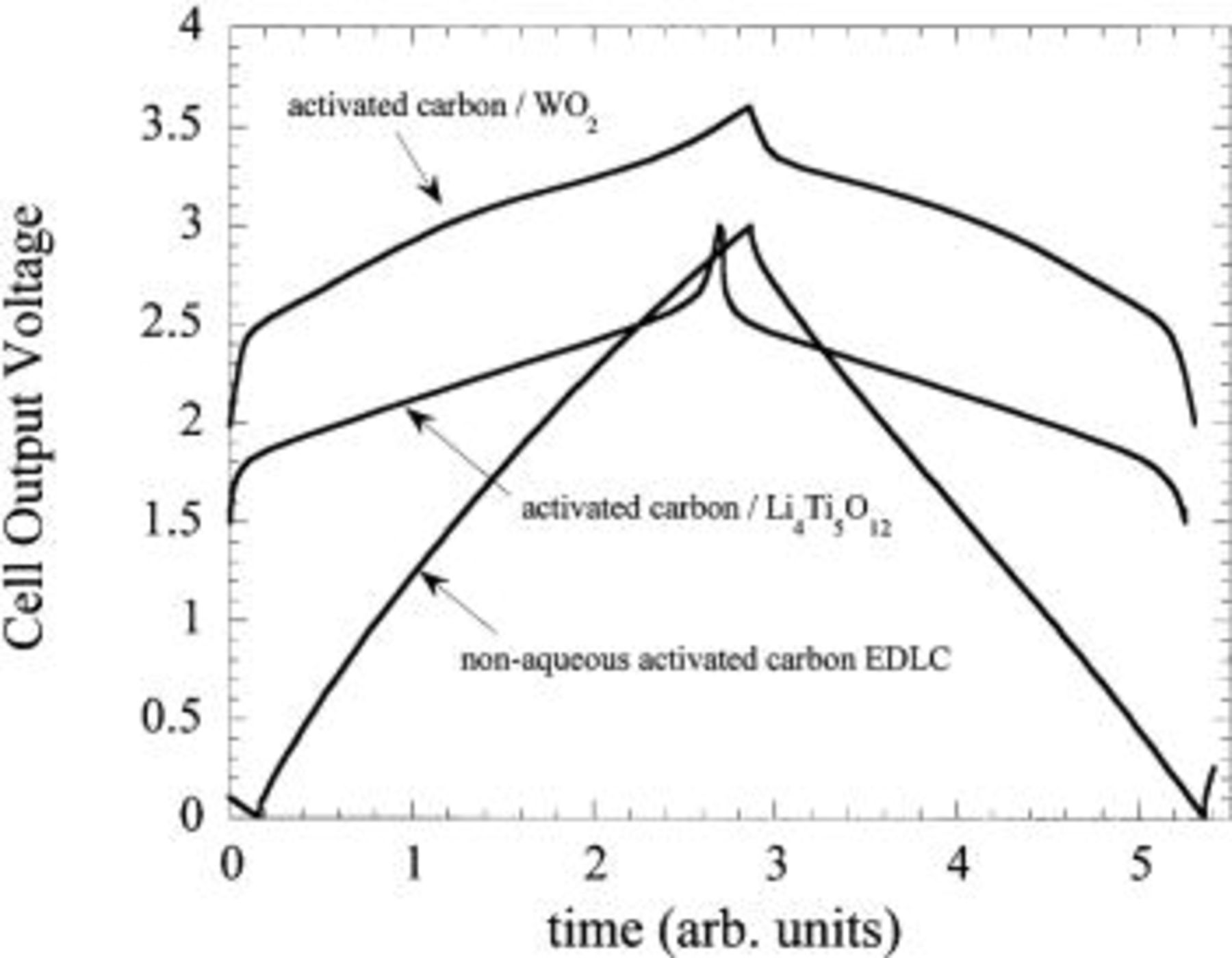
Figure 22. Cell output voltage comparison for one charge-discharge cycle of an activated carbon/activated carbon nonaqueous EDLC, a  /activated carbon asymmetric hybrid cell, and a
  /activated carbon asymmetric hybrid cell.
Assuming a 100% excess of  salt (286 mAh/g),
  (160 mAh/g), activated carbon (40 mAh/g), the calculated energy density of the material system based on an average voltage of 2.25 V is 58.5 Wh/kg. Utilizing an alternative negative electrode with an average voltage of −2.5 (SHE) and identical capacity of 160 mAh/g, the energy density of the system increases to 85 Wh/kg. Current collectors, polymers, solvent, and packaging will lower these numbers by at least 50% based on our experiments with the plastic prototype cell discussed above. These values are still competitive with thin film Pb acid technology and are clearly superior to those of nonaqueous EDLC technology. Improvement in the positive electrode materials, which exhibit enhanced capacity via increased capacitance or pseudocapacitance will cause these numbers to improve considerably.
We have limited our discussion to nonaqueous systems. Nonaqueous electrolytes have a conductivity, which is typically one to two orders of magnitude lower than that of aqueous electrolytes, however, they have a large electrochemical window of stability (0-5 V  ). This voltage stability is an asset in the development of the next-generation fast-charge high-energy density asymmetric systems.
The hybrid cell energy density can be improved through selective use of the appropriate existing and new negative and positive electrode materials. High specific capacity, low surface area p-doped organoredox positive electrodes hold much promise as the next generation positive electrodes. The use of a lower voltage negative electrode such as transition metal nitrides, conversion oxides, or low voltage intercalation oxides will increase the energy density significantly. An example of the improvements that can be ascertained can be seen with the intercalation compound 
 intercalates lithium at approximately 0.7 V
  31 A properly balanced asymmetric hybrid cell was fabricated utilizing an activated carbon positive electrode and a
  negative electrode. Three-electrode characterization of the cell is shown in Fig. 23. Compared with the three electrode characterization of the
  /activated carbon asymmetric hybrid cell of Fig. 12, the
  intercalates
  at a voltage 1 V more negative than
  This decrease in negative electrode potential results in an asymmetric hybrid cell with an output voltage of 3 V. Figure 22 compares the output voltage of a 3 V nonaqueous EDLC we fabricated using tetraethylammoniatetrafluoroborate in acetonitrile, a
  /activated carbon asymmetric hybrid, and a
  /activated hybrid asymmetric hybrid. The use of a
  negative electrode increases the energy density of the
  negative electrode based asymmetric hybrid by 30%.
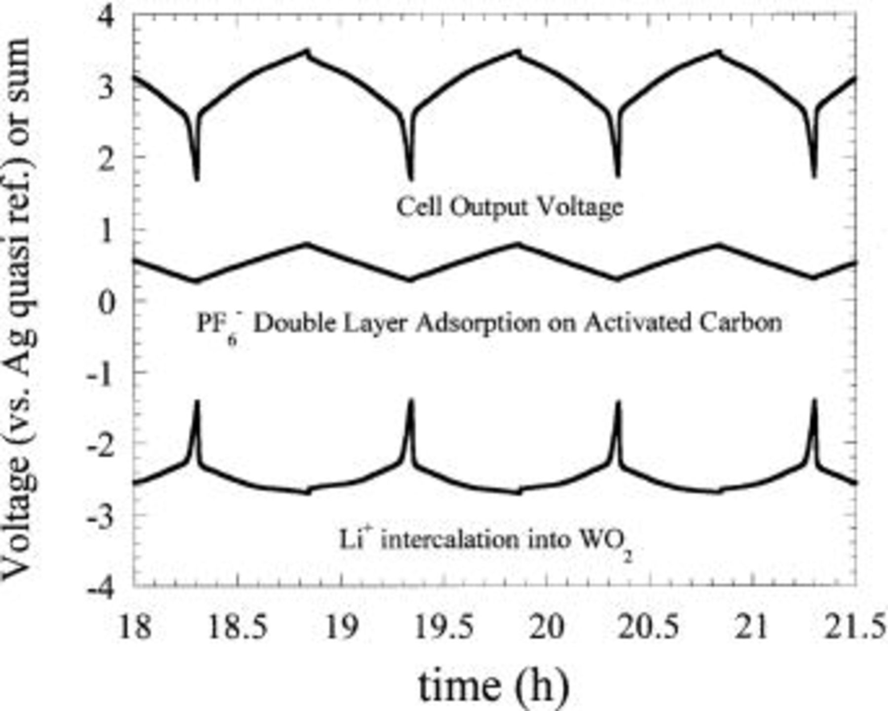
Figure 23. Three-electrode characterization of charge-discharge cycles of a  /activated carbon asymmetric hybrid cell.
Conclusions
We have introduced a nonaqueous electrolyte asymmetric hybrid electrochemical cell. The positive electrode material consists of a high-surface area activated carbon which undergoes a nonfaradaic process with the anion species of the electrolyte, very similar to that observed in a nonaqueous EDLC. The negative electrode is a lithium insertion compound, which inserts lithium to the theoretical limit upon the charging of the cell. All the ions for the negative electrode insertion process are contained within the electrolyte solution. Activated carbon and a high-rate, long-life nanostructured  that we developed were identified as suitable materials for use as the positive and negative electrode, respectively. The hybrid cell utilizing these materials exhibited high capacity, a much improved voltage profile, and a 400-500% energy density increase with respect to today's nonaqueous nonaqueous EDLC technology while maintaining long cycle life characteristics and 90% capacity at 10C charge rates. The activated carbon positive electrode was investigated by cyclic voltammetry. Electrolyte oxidation was found to be reduced considerably after passivation.
  was introduced as a possible replacement for
  Silver was found to be a suitable quasi-reference electrode for routine three-electrode characterization in nonaqueous systems.
Acknowledgments
The authors would like to give special thanks to P. Rickman, J. Gural, A. S. Gozdz, J. M. Tarascon, A. Singhal, and G. Skandan.
Telecordia Technologies assisted in meeting the publication costs of this article.