
Abstract
Different species of insects and birds fly differently. Their wing forms and wing motion are different. Understanding the purpose of this difference will lead to successful development of flapping wing vehicles for different purposes. This paper discusses the influence of one of the important factors which affects the aerodynamic performance of a flapping wing: the local instantaneous relative wind. Its distribution along the span of a flapping wing has been analyzed for the practical flight range of advance ratios ranging from 0 to 1.5 and stroke plane orientations ranging from 0 to 90°. In this domain, the variation of spanwise distributions of magnitude and direction of relative wind are presented separately for downstroke and upstroke of a flapping cycle. Accordingly, qualitative suggestions are given for wing planform design, orientation and twist of the wing, and actuation of wing for effective utilization of the relative wind and obtaining the necessary force distributions for different flight phases. The formulation presented will be helpful for experimenting flapping wings in hovering and forward flight; especially for setting the wing twist for a required angle of attack distribution and designing the flapping kinematics in upstroke and downstroke.
Export citation and abstract BibTeX RIS
1. Introduction
Flights of Cinsects, birds and bats have been studied by researchers for many decades. Methods like in vivo study [1–7], experimenting with physical models [8–12], computational fluid dynamic (CFD) analyses [13–15] and analyses with theoretical formulations [14, 16, 17] were employed for qualitative and quantitative understanding. In vivo studies help in understanding the force production mechanism of natural flyers at various flight phases and conditions. However, the effects of variation of wing kinematics cannot be studied thoroughly; since natural flyers always tend to actuate their wings either in performance effective or energy efficient ways, whichever is required at that moment [18]. Experimenting with physical models and CFD would help in this aspect. However, without a proper theoretical model to support, these methods would not be systematic but rather iterative and more costly in terms of time and money. Quasi-steady blade element approach is a well-established and useful theoretical method for flapping wing analyses. Moreover, it is useful in analyzing flows and forces in the wing airfoil section level; which would help in designing the wing and its kinematics for different flight requirements. Hence, we present the formulations in this paper based on this approach.
It is important to manage optimally the aerodynamic force-distribution on the wing of any flying object, in the aerodynamic and structural points of view. In a flapping wing section, the resultant aerodynamic force is the summation of translational force, rotational force, force due to added mass effect, force due to clap and fling effect, and force due to wake capture at stroke reversals [19, 20]; of which translational force is the major contributor. All of these components depend on density of air, reference area, force coefficients and the relative wind velocity. In flapping wings, the possibility of varying density is limited; since mostly they operate at low altitudes. However, the possibility of varying wing planform, force coefficients and relative wind is vast. While the translational aerodynamic force has a linear relation with other parameters, it depends on square of the relative wind velocity. Hence, relative wind plays the major role in producing the aerodynamic forces. Moreover, relative wind influences the wing planform and force coefficients also; since wing planform is decided according to the required force distribution and force coefficients depend on angle of attack, Reynolds number and Mach number, which in turn depend on relative wind.
In fixed-wing flight, managing the force distribution along the span can be done with a little effort in geometric design of the wing; since every section of the wing sees mostly the same relative wind. However, in flapping wings, the relative wind seen by every wing section differs, because of the induced relative wind component due to wing flapping. Hence, in addition to the geometric design of the wing surface, wing kinematics (with degrees of freedom including the movement of the whole wing and also its shape modifications by flexing, twisting etc) should also be optimized. In a flapping wing, there are possibilities for the relative wind to vary in magnitude as well as in direction from wing root to the tip, based on the wing kinematics. Distribution of relative wind magnitude can be managed by the wing actuations at the wing pivot (applicable for non-articulated wings only). However, the variation in relative wind direction along the span may require a wing twist, for enabling the required angle of attack at every wing section. In hovering flight, relative wind on a wing section is strictly a function of the wing kinematic parameters only. However, in other phases, especially in forward flight, the relative wind depends also on the freestream due to flight velocity, in addition to wing kinematic parameters.
Considerable works which studied the effect of wing kinematics on flapping wings have been done previously. Some works were on observing and understanding the wing kinematics of natural flyers [1–7]. Others were aimed at producing optimal simplified functions of kinematic parameters [19, 21–23]. While many works were on hovering flight, there are some studies which focused on wing kinematics effects in forward flight [24]. Some works even modelled instantaneous local velocities along flapping wings [25–27]; and these models were mostly based on specific kinematics of their working models. A mathematic model which is capable of predicting the effects of variations of wing kinematics and flight parameters, would be helpful, especially for experimental studies. In previous experimental works on forward flight [9, 10, 28], the effect of wing kinematics and freestream were studied and related to advance ratio. However, these works were restricted to horizontal stroke plane flapping.
In this paper we produce necessary formulations for taking these experiments to the next level, for the cases of inclined stroke plane flapping. Section 2 contains the mathematical model required to know the instantaneous local relative wind (magnitude and direction) at every wing section, at any position of wing, flapped with any speed, in any stroke plane orientation, flying at any flight speed. It will be helpful in designing the wing planform for required load distribution and also for setting the wing twist for the required angle of attack distribution. Moreover, a discussion on the effect of relative wind distribution on force distribution and local angle of attack is presented; through which the necessity for variation of wing kinematics for varying flight parameters is qualitatively stated. This can be used for further deeper quantitative analyses for different flight purposes like hovering, low-speed flight, high-maneuvering flight, high-speed cruising flight, etc.
2. Mathematical model
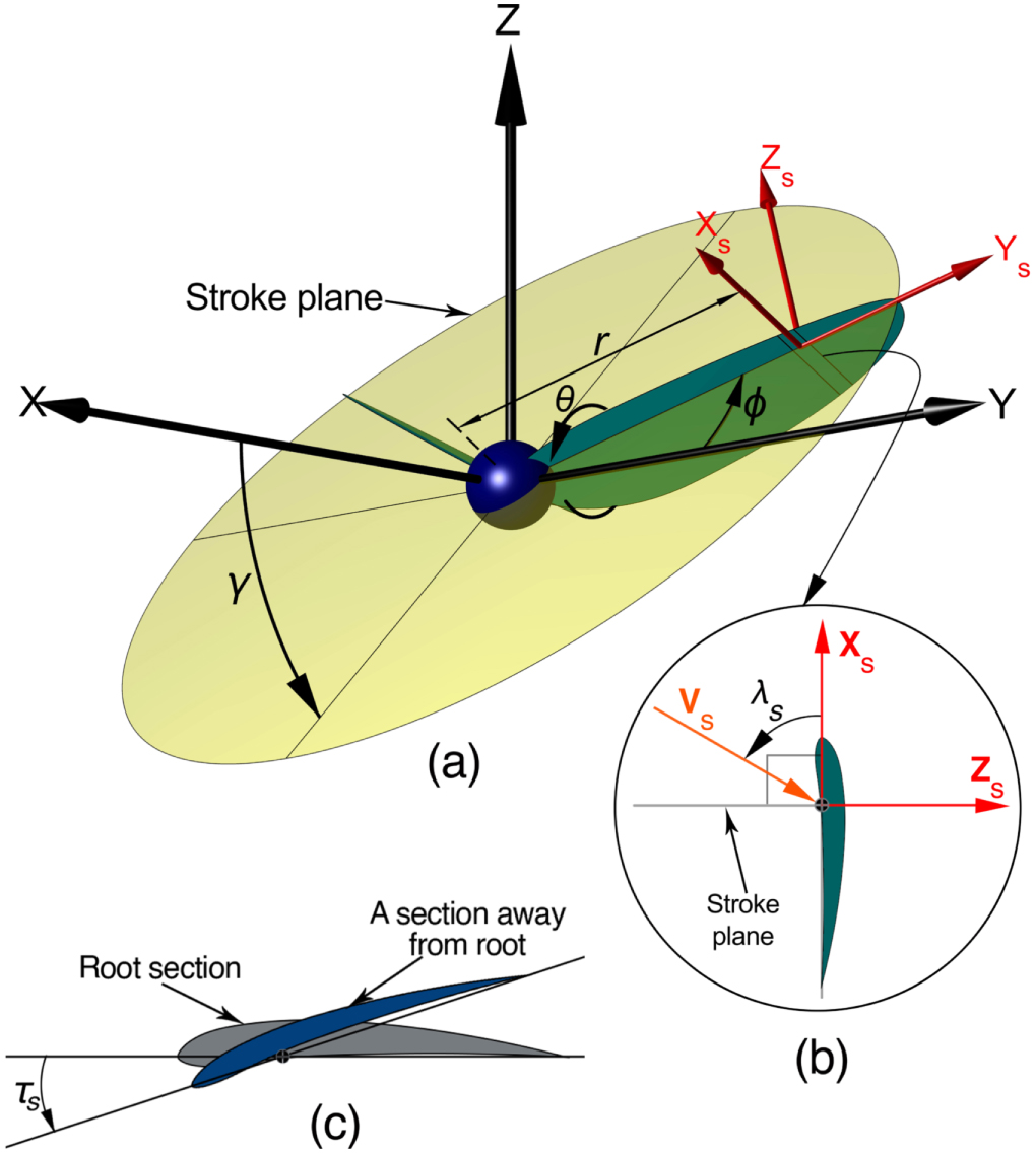
The model presented here is compatible with quasi-steady blade-element approach for flapping wing analyses. All wing motion are defined in wind axis coordinate system XYZ (shown in figure 1(a)) with origin fixed to the wing pivot, such that the freestream due to flight is always in the negative X direction. Hence, this model can be used for all flight phases including hovering, takeoff, climbing, level flight, descend and landing; except for gliding. The wing motion is restricted to the stroke plane and out-of-plane deviations are considered zero; to study the effect of stroke plane orientation substantially with ease. Wing flexure in its normal direction is considered zero; hence the wing axis is always a straight line. The axis of the wing is placed passing through the quarter chord locations of all sections. The effect of wing rotation about its axis on the relative wind is neglected; hence the relative wind of a wing section defined here is what seen by the wing axis at that section.
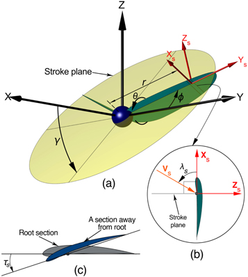
Figure 1. Coordinate system showing the wing kinematic parameters. All axes and angles follow the convention of right-handed coordinate system. (a) XYZ is right-handed wind axis system with X pointing the flight direction and Y pointing the lateral direction outward the left side of the flyer. XsYsZs is the local coordinate system of a wing section (or blade element) with Xs along the chord pointing forward the leading edge, Zs pointing normal direction of dorsal surface. γ is stroke plane orientation with the flight direction. ϕ is wing angular position in the stroke plane. θ is wing rotation about its spanwise axis. r is the location of the wing section from the wing pivot. (b) Sectional side-view of unrotated (θ = 0) and untwisted (τs = 0) wing at r, showing the local relative wind vector Vs and its inclination λs with the chordwise direction Xs. Refer to figure 3 for visualizing the relative wind distribution along span of the wing. (c) τs denotes the wing twist, which is the rotation of a wing section about the wing lateral axis and is measured from the chord of the root section.
Download figure:
Standard image High-resolution imageUsing proper Euler angle rotations, the position of any wing section at a distance r from the wing pivot can be derived in XYZ axes as

where, 
 and
and  represent unit vectors in X, Y and Z directions respectively.
The unit vectors along the wing section local coordinate axes Xs, Ys and Zs (see figure 1(a))—which also represent the chordwise, lateral and normal directions of an un-twisted wing section respectively—at any instant can be derived as

The relative wind seen by a wing section is the summation of the contributions by the freestream and that due to wing motion; and is represented as  where
where  This relative wind is not always in the plane of wing airfoil section and generally have an additional component which is in the lateral direction, which negligibly contribute to force production by that section. This component of Vr
along Ys is usually neglected and the component in the plane of wing section (Xs Zs plane) is generally considered for quasi-steady blade-element analyses [10]; and is found by
This relative wind is not always in the plane of wing airfoil section and generally have an additional component which is in the lateral direction, which negligibly contribute to force production by that section. This component of Vr
along Ys is usually neglected and the component in the plane of wing section (Xs Zs plane) is generally considered for quasi-steady blade-element analyses [10]; and is found by  as
as

Using this equation, it can be proved that Vs is not always in the stroke plane, except for the cases of hovering (J = 0) and horizontal stroke plane flapping (γ = 0) which were mostly taken for investigation [9, 10, 19, 23] (see figures 2 and 3).
For the purpose to be used in aerodynamic force calculations, the magnitude of Vs can be obtained as

For generalization this can be further non-dimensionalized by dividing with reference wing tip velocity as  and obtained as

where, J is advance ratio given by 
 is the normalized radial location of wing section given by
 is the non-dimensional wing angular velocity given by
 can be taken to be the maximum angular velocity
  in a flapping cycle (useful for effectiveness studies) or the average angular velocity
  (useful when cycle-average parameters are analyzed). Since
  is
is  times
times 
 quantifies how effectively the wing movement is utilized for relative wind generation for force production.
Equation (3) can be used to find the direction of the relative wind in any wing section. However, for simplifying the process we introduce an angular parameter λs
defined as the angular displacement of Vs
from the chordwise direction ( ) of an unrotated, untwisted wing section. Accordingly, λs
can be obtained by
) of an unrotated, untwisted wing section. Accordingly, λs
can be obtained by

which can be further reduced to

The signum function in the above equation gives sign to λs,
which in turn represents whether Vs
is displaced counter-clockwise (+ve) or clockwise (−ve) from  when viewed from the wing tip. The value of λs
at the wing root (i.e., at
when viewed from the wing tip. The value of λs
at the wing root (i.e., at  )—hereafter designated as
  —decides the rotation of the wing which in turn decides the angle of attack at the wing root. The variation of λs
(i.e.,
—decides the rotation of the wing which in turn decides the angle of attack at the wing root. The variation of λs
(i.e.,  ) along the span decides the twist required to achieve the required angle of attack distribution along the span of the wing. Accordingly, for obtaining a required angle of attack
  at the root, the wing rotation to be made is

Then, for obtaining an angle of attack  at any wing section, the wing twist required at that section is given by

The wing twist  denotes the rotation of a wing section about the wing lateral axis after θ is applied at the wing root (see figure 1(b)).
  follows the same sign convention as θ.
3. Overview of the study
3.1. General characteristics of relative wind distribution in hovering and forward flight
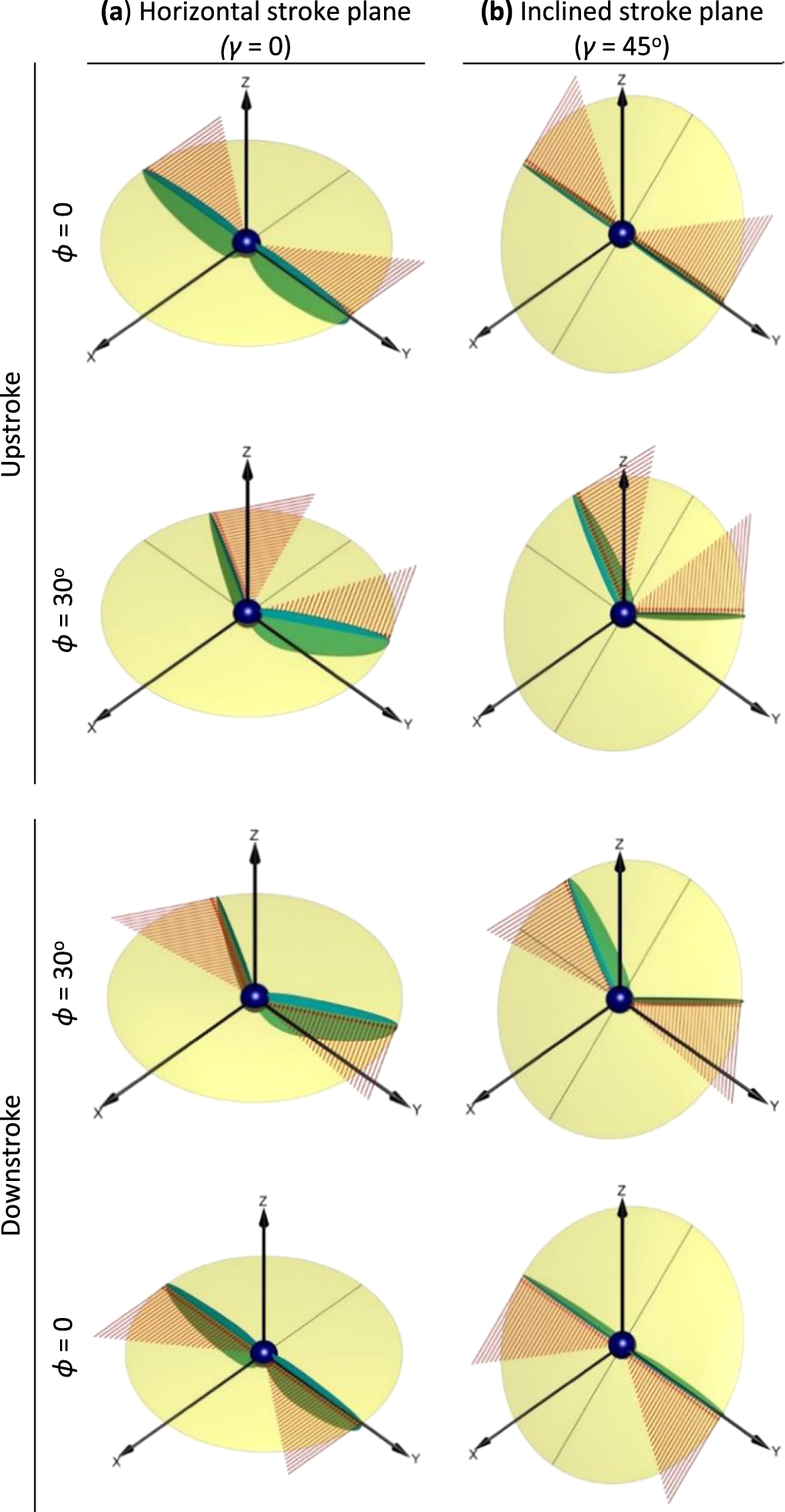
Hovering is the simplest case in which the relative wind on the wing depends only on the wing motion; since the flight velocity is zero. As shown in figure 2, the relative wind for all wing sections from root to tip, lie in the stroke plane; hence there is no variation in direction along the span. The magnitude of the relative wind increases linearly from zero at the root to a maximum equal to the wing tip velocity at the wing tip. This distribution exists common for both downstroke and upstroke of flapping irrespective of the stroke plane orientation 1 . Since the distribution is planar and always at one side of the wing, adjusting the wing rotation at the wing pivot would be just sufficient for enabling the required angle of attack at the wing sections. Hence a rigid flapping wing would be sufficient for the case of hovering.
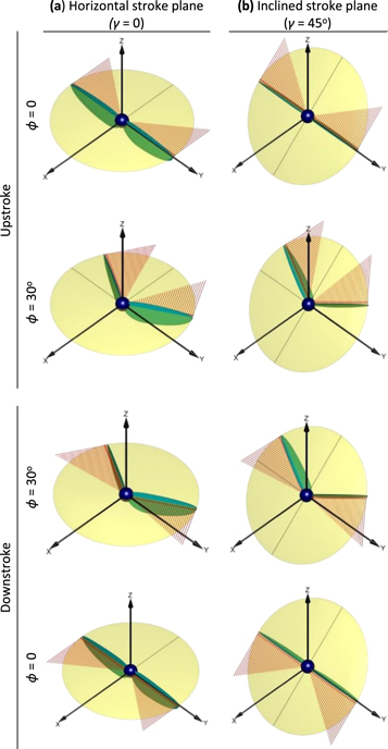
Figure 2. Velocity distribution along the span of a flapping wing during hovering flight (J = 0). For clear visualisation, the wing is set at zero rotation (θ = 0).
Download figure:
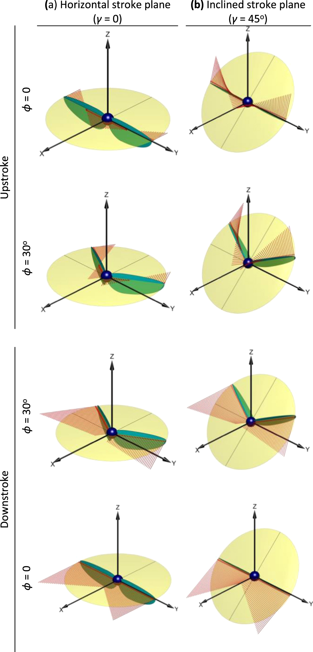
Standard image High-resolution imageThe complication starts when the freestream velocity comes into picture as the flyer starts moving. In forward flapping flight, it is unrealistic to have zero stroke plane orientation. However, it is a simplified case for understanding the effect of advance ratio; hence it was chosen for experimentation in previous works related to forward flight [9, 10]. In those works, rigid flat wings were used and the angle of attack was directly related to the wing rotation as α = (π/2–θ), for simplicity. If referred to the velocity distribution (figure 3(a)), this works fine for downstroke of flapping. However, this assumption is not applicable for all the wing sections in upstroke of the wing. Although the relative wind distribution is linear and planar, it is not at the same side of the wing as in the case of downstroke. At wing sections nearer to the wing pivot, there is a possibility for the magnitude of the wing motion contribution to be lesser than that of freestream. Hence, although the wing is moved backward, the relative wind will not oppose the wing and will be in the same direction of wing motion. Because of this kind of relative wind distribution, a rigid flat wing with a given rotation angle will not enable a constant angle of attack throughout the span. Since there is a change in direction of the relative wind, there is a necessity for changing orientation of the wing section along the span; in other words, a wing twist is required. The relative wind distribution in the forward flight with inclined stroke plane (the realistic flapping forward flight case) is not even planar (figure 3). It has non-linear variation in magnitude and continuous change in direction in the 3D space. It is notable that these variations are lesser in downstroke compared to that of upstroke.

Figure 3. Velocity distribution along the span during flapping forward flight (J = 0.5). For clear visualisation, the wing is set at zero rotation (θ = 0).
Download figure:
Standard image High-resolution image3.2. Scope of the analysis
A membranous wing—as used in many flapping wing flying models—will passively (may be partially) adapt its shape, generating the twist to accommodate the changing relative wind directions along the span. However, for deeper knowledge on this relative wind velocity distribution—which would aid in effective design of wing and its kinematics—we analyzed it for variations in magnitude and direction with respect to the variations in flight speed and flapping speed (in terms of the advance ratio J), stroke plane orientation γ, and the wing's flapping position ϕ. For studying the effect of magnitude of relative wind velocity,  is plotted across the wing span for various wing flapping positions at different combinations of advance ratio and stroke plane orientation (figures 4 and 6); since the translational aerodynamic force depends on square of the relative wind velocity. Moreover,
  non-dimensionally represent the local dynamic pressure available at a wing section for force production; since flapping flight mostly happens in incompressible flow regime where density change is negligible. This is also useful in determining the effectiveness in utilizing the freestream and flapping action towards force production; as
  represents the magnitude of the local dynamic pressure
  compared to the maximum contribution possible by the wing's flapping motion
  Further, for studying the effect of direction of relative wind of a wing section, λs
is plotted across the wing span for various wing flapping positions at different combinations of advance ratio and stroke plane orientation (figures 5 and 7).
Further, for studying the effect of direction of relative wind of a wing section, λs
is plotted across the wing span for various wing flapping positions at different combinations of advance ratio and stroke plane orientation (figures 5 and 7).
According to the definition of the advance ratio ( ), an increase in it can be visualized as an increase in flight velocity and/or a decrease in flapping angular velocity and/or a decrease in span of wing from root to tip. However, generally, it is more often used in the context of flight velocity. Generally, flapping flyers fly with advance ratios ranging from 0 to 1.3 [9, 10, 29, 30]. Hence, we restricted our analysis in the advance ratio range 0 to 1.5. As the flight advances in velocity, the flapping changes from a horizontal stroke plane to a vertical stroke plane [1, 3, 30–32]; hence, a stroke plane orientations in the range 0 to 90° were taken for analysis. A full flapping range (ϕ = 90° to ϕ = −90°) with a constant flapping velocity (
 ) was considered; since it would simplify the analysis like a revolving wing experiment [9, 12, 33], moreover, would represent a maximum effective flapping case [23]. Accordingly, hereafter,
  will be used in place of
The distribution of magnitude of the relative wind will determine the aerodynamic force distribution and also the structural stresses along the wing span. A cantilever wing design would prefer the loads to reduce as moving towards the free end. This can be partially achieved by the wing planform design; however, proper management of relative wind distribution is also required.
Whereas, the change in orientation of the relative wind along the wing span influences the angle of attack of every wing section; which in turn will affect the force distribution. Hence, there is a necessity for dynamic variation of wing twist throughout a flapping cycle, for enabling the required angle of attack distribution along the span. For example, if a flapping wing is expected to have constant angle of attack αs
throughout its span, a flat plate wing with a given rotation angle, would not work except for the case of a hovering flight (J = 0) and a hypothetical forward flight with zero stroke plane orientation flapping (only in downstroke). Instead, the wing should first be rotated by an angle equal to  and then twisted such that the twist angle
  of any section with respect to the root section should be equal to
  Other angle of attack distributions can be obtained by proper manipulation of the wing twist using equation (9) as required. However, the wing structural constraints may not permit the required dynamic wing twist. Hence, there is a requirement for proper design of wing kinematics, such that the dynamic variations of distributions of relative wind magnitude and direction are minimized in a flapping cycle; which would reduce the complexities imposed on the flapping mechanism and enable an effective flapping flight with minimum vibration and fatigue. With these basic understandings, figures 4–7 can be consulted for deciding the design of wing and its flapping kinematics for specific flight requirements.

Figure 4. Distribution of square of nondimensional relative wind velocity in wing section  along the span of a flapping wing during downstroke of flapping. Each row of plots corresponds to same advance ratio J which varies from 0 to 1.5 from top to bottom. Each column of plots corresponds to same stroke plane orientation γ which varies from 0 to 90° from left to right. The same arrangement is followed for figures 5–7. Each plot has distributions for wing positions in range
  taken in intervals of 10°. Wing positions which are equally away from the mid position (ϕ = 0) produced same curve which exactly overlap. This phenomenon is also observed in figures 5–7.
Download figure:
Standard image High-resolution image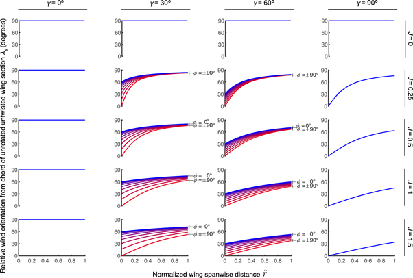
Figure 5. Distribution of the angular displacement of Vs
from the chord direction of an unrotated untwisted wing section  along the span of a flapping wing during downstroke of flapping. Positive values of
  denote counter-clockwise displacement; which should be understood as the relative wind attacks the ventral side of the unrotated untwisted wing.
Download figure:
Standard image High-resolution image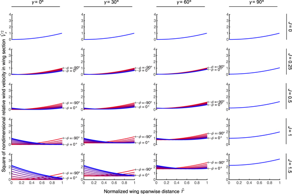
Figure 6. Distribution of square of nondimensional relative wind velocity in wing section  along the span of a flapping wing during upstroke of flapping. Note that the ordinate axes have different scale compared to those of figure 4.
Download figure:
Standard image High-resolution image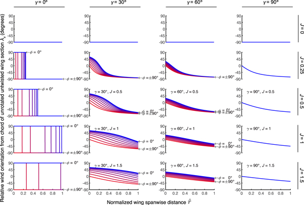
Figure 7. Distribution of the angular displacement of Vs
from the chord direction of an unrotated untwisted wing section  along the span of a flapping wing during downstroke of flapping. Note that the ordinate axes have different scale compared to those of figure 5. Positive and negative values of
  denote counter-clockwise and clockwise displacements respectively; in turn denote the cases of relative wind attacking the ventral side and dorsal side of the unrotated untwisted wing respectively.
Download figure:
Standard image High-resolution image
4. Analyzing the hovering flight
In hovering flight, the advance ratio J is zero. For J = 0,  distribution does not change with respect to wing position or stroke plane (see figures 4 and 6). Moreover, λs
is constant throughout the span. Hence, hovering does not require a dynamic wing twisting. However,
distribution does not change with respect to wing position or stroke plane (see figures 4 and 6). Moreover, λs
is constant throughout the span. Hence, hovering does not require a dynamic wing twisting. However,  has lower values compared to that of non-zero advance ratios. Hence, a high value of
  is required for obtaining the necessary dynamic pressure for producing the necessary lift. Hovering flyers are meant for flying through small confined spaces with exceptional maneuverability; which would require a low wing span R. Hence, the only possible way to get the necessary dynamic pressure for sustained flight is by increasing
  with a high frequency flapping. Considering the upstroke, it too has the same
  distribution as the downstroke (see figures 4 and 6). Hence, just a reversing of the wing pitch at the wing pivot would make the upstroke work very similar to the downstroke, in hovering.
Another notable property of hovering is: negligibly small  near the wing root, which reaches zero at the root section. Hence, whatever may be the speed of flapping, the wing region near the root section will receive a very small dynamic pressure and will contribute negligibly towards the aerodynamic forces of the wing. This means that, there will not be a considerable loss in terms of aerodynamic force production, even if this portion of the wing does not exist. Hence for hovering dominant flyers, the portion of the wing near the wing pivot can be trimmed off to a minimum chord thickness which is required for structural integrity. Doing so would remove that useless mass and also its inertial moment which would cost on the flapping effort. This is one of the reasons why hovering insects have minimum chord length near the wing pivot and the wing width increases as moving along the span towards the tip [34].
5. Analyzing the forward flight
Figures 4–7 show all the possible combinations of advance ratio J and stroke plane orientation γ. However, in practical conditions, forward flapping flight with all the combinations is not possible. For a given configuration of flyer, the drag variation with flight velocity is fixed; hence the thrust to lift ratios of the flyer, to be maintained for different flight velocities, are also fixed. Hence, the liberty to change the stroke plane orientation corresponding to a flight velocity is very limited. However, the possibility for changing advance ratio ( ) for a given flight velocity is not as stringent as that for the stroke plane orientation; since advance ratio has two parameters in the denominator viz wing span R and flapping angular velocity
  to work with. Unlike hovering, in forward flight, the downstroke of flapping contributes mostly towards the force production [20, 35, 36]. Hence, for any specific flight purpose, firstly the wing and its kinematic function need to be optimized for downstroke.
5.1. Downstroke
5.1.1. Inferences based on distribution of relative wind magnitude
The common characteristic of  seen in downstroke of all cases is: its magnitude increases exponentially from root to tip of the wing (see figure 4). Higher dynamic pressure towards the tip can be related to higher maneuverability, higher flexural loads and higher hinge moment to overcome for flapping. Accordingly, a high-maneuver wing should have a broader area distribution near the tip. However, to take care of structural integrity, the wing span can be reduced and flapping speed can be increased for sufficient force production. This is evident as the natural high-maneuver flyers have low aspect ratio wings with broader area near the wing tip, operated at high frequency [34, 35]. In the case of high-speed cruising flyers like Albatross, the wings have high aspect ratio and pointed wing tips; since they do not require quick maneuvers, however require efficient flying with minimized induced drag.
Another noticeable aspect from figure 4 is: as the flight velocity increases, considerable value of  can be noticed at and near the wing root. It should be properly utilized; especially during high-speed cruising where wings cannot afford to higher loads towards the wing tip. This can be managed by having highly cambered airfoils—having higher lift generation abilities at low speeds—towards the root section. This feature is already observed in bird wings [35, 37]. Moreover, birds are capable of changing the wing camber dynamically.
During downstroke, in most of the cases,  is maximum at the mid flapping position ϕ = 0, and reduces as the wing moves away from the mid position (see figure 4); even if a constant velocity flapping is considered, as in the case of figure 4. Since
  can be considered as aerodynamic force producing ability, it can be concluded that flapping wings have the maximum force producing ability or wind utilizing effectiveness at the mid position ϕ = 0. This property is also observed in experimental studies [9, 10]. Moreover, for all wing positions other than the mid position, the relative wind utilization ability is found to increase with increase in stroke plane orientation and decrease in advance ratio. This can be observed from figure 4, as the curves of ϕ ≠ 0 approach the curve of ϕ = 0 as the stroke plane orientation approaches γ = 90° and also as advance ratio J approaches zero. Advance ratio cannot be zero in forward flight, moreover should increase as the flight velocity increases, for any wing configuration. This is because the possibility to reduce advance ratio at higher flight velocities, by increasing the flapping speed is limited by the higher wing loads at that velocities. On the other hand, stroke plane orientation is required to increase with increasing flight velocity; as the required thrust to lift ratio increases with flight velocity. Hence, in this aspect, nature itself helps in effective utilization of relative wind. It is for this reason, natural flyers cruise at a speed corresponding to a thrust to lift ratio obtainable at near vertical stroke plane flapping. However, reducing the flapping amplitude with flight speed is recommended for effective utilization of resultant aerodynamic force as lift and thrust while reducing the side-force component [38, 39]. Moreover, according to figure 4, for forward flight with inclined stroke-plane flapping, reducing the flapping amplitude will enable the wings to operate in region of acceptable relative wind utilization.
The plots shown in figures 4–7 are applicable for all flight phases including takeoff, climbing, flapping descend and landing in addition to hovering and level forward flight; since the mathematical model in this paper is defined in a wind-axis coordinate system. In this perspective, figure 4 shows that for any flight phase if the stroke plane is perpendicular (not necessarily vertical) to the flight direction, the relative wind utilization is maximum. Natural flyers utilize this fact effectively in their flight plan. They quickly cross the speeds less than the cruising speed, taking an inclined flight path like climbing or gliding rather than a horizontal path. For climbing path the thrust to lift ratio is higher than that for level flight [40]. Hence, the stroke plane orientation required will be higher and hence the flapping will shift into effective relative wind utilization zone. Natural flyers do not have a purpose for a slow (slower than its cruise velocity) level flight. However flapping drones will have such purpose. In such cases, high frequency flapping with less stroke amplitude will serve for effective wind utilization.
5.1.2. Inferences based on distribution of relative wind direction
While spanwise distribution of  decide the magnitude of aerodynamic force distribution, λs
distribution decides the orientation of the resultant aerodynamic force, and hence decides the wing twist necessary for a desired spanwise angle of attack distribution. Figure 3 shows that, in downstroke for all wing sections, the relative wind is always above the stroke plane and at the ventral side of the unrotated untwisted wing. This can be confirmed from figure 5, since λs
values for all sections at all cases have positive value and are less than 90°. Except for
decide the magnitude of aerodynamic force distribution, λs
distribution decides the orientation of the resultant aerodynamic force, and hence decides the wing twist necessary for a desired spanwise angle of attack distribution. Figure 3 shows that, in downstroke for all wing sections, the relative wind is always above the stroke plane and at the ventral side of the unrotated untwisted wing. This can be confirmed from figure 5, since λs
values for all sections at all cases have positive value and are less than 90°. Except for 
 for all positions for all cases have positive value. Moreover, moving along the wing span, λs
value increases. Hence, in addition to a positive wing rotation for setting the angle of attack at the root, an increasing wing twist towards wing tip in the same direction of wing rotation should be enabled if a constant angle of attack or decreasing angle of attack distribution is desired. Figure 5 confirms that there is no wing twist required in hovering (J = 0) and flapping in horizontal stroke plane (γ = 0); however, a wing rotation would be required for setting the angle of attack.
for all positions for all cases have positive value. Moreover, moving along the wing span, λs
value increases. Hence, in addition to a positive wing rotation for setting the angle of attack at the root, an increasing wing twist towards wing tip in the same direction of wing rotation should be enabled if a constant angle of attack or decreasing angle of attack distribution is desired. Figure 5 confirms that there is no wing twist required in hovering (J = 0) and flapping in horizontal stroke plane (γ = 0); however, a wing rotation would be required for setting the angle of attack.
For a wing position, in a given stroke plane orientation,  is constant for all advance ratios except J = 0; since at wing root the relative wind is contributed only by the freestream. This concludes that, for a given flapping velocity function
  in a given stroke plane, the required wing rotation function
  is same for all advance ratios; provided the angle of attack requirements are same. For a given flight condition,
  value increases from zero at
  to a maximum value of
  at
at  This demands the wing rotation to be minimum in the beginning a flapping stroke and should be increased to a maximum at the mid stroke (
 ) and again reduced to minimum at the end of the stroke. This trend is observed in most of the natural flyers [1, 19, 41]. However, the twist required for a given angle of attack distribution is minimum at the mid-position and increases as the wing moves away from the mid position; since variation of λs
is minimum for the curve of
) and again reduced to minimum at the end of the stroke. This trend is observed in most of the natural flyers [1, 19, 41]. However, the twist required for a given angle of attack distribution is minimum at the mid-position and increases as the wing moves away from the mid position; since variation of λs
is minimum for the curve of  in all cases. This also suggests that if a wing cannot be twisted more, the flapping amplitude can be reduced to bring the required twist into the operable range. As the advance ratio increases, the required twist reduces (since the variation of λs
reduces with advance ratio) and as the stroke plane orientation increases, the required rotation also decreases (since
in all cases. This also suggests that if a wing cannot be twisted more, the flapping amplitude can be reduced to bring the required twist into the operable range. As the advance ratio increases, the required twist reduces (since the variation of λs
reduces with advance ratio) and as the stroke plane orientation increases, the required rotation also decreases (since  of a wing position decreases with increasing γ). This fact was observed in birds [31, 42, 43] and also experimentally proven [18]. Moreover, flapping with constant velocity (the case used for plotting figures 4–7) throughout a stroke is impractical. The wing should accelerate in the beginning of a stroke and decelerate towards the end of a stroke. Hence, the instantaneous advance ratios at those positions are relatively higher than that in the mid position. This is another work of nature to reduce the difficulty in wing twist. Accordingly, it is not difficult to minimize the dynamic variation of wing twist by a proper variation of flapping speed
  in a stroke. Managing the wing twist is not a difficult task for natural flyers. However, for artificial flapping flyers, it is a long way to go achieving it by an active wing morphing mechanism.
When the stroke plane is perpendicular to the flight direction (γ = 90°),  is zero for all wing positions at all advance ratios. This concludes that a rotation of just
  at wing root is required for a perpendicular flapping case. This stroke plane orientation (γ = 90°) is maintained usually at cruising forward flight where the advance ratio will be higher, where the twist requirement is less (since variation of λs
is lesser for higher advance ratios). Hence naturally the cruising forward flight becomes the most comfortable flight phase, in terms of the wing actuation.
at wing root is required for a perpendicular flapping case. This stroke plane orientation (γ = 90°) is maintained usually at cruising forward flight where the advance ratio will be higher, where the twist requirement is less (since variation of λs
is lesser for higher advance ratios). Hence naturally the cruising forward flight becomes the most comfortable flight phase, in terms of the wing actuation.
In general, downstroke requires the wing to be rotated and twisted forward. More the rotation and/or twist towards front, the more is the thrust contribution by the resultant aerodynamic force. Hence, naturally, low advance ratio flapping is capable of producing more acceleration (since the rotation and twist requirements are more). In a more twisted wing section the local drag also contributes towards lift of the flyer [29]. All these observations and inferences reveal: by nature, the relative wind distribution, and the related wing rotation and twist requirements are interlinked such a way that it aids for maintaining the required thrust and lift values for different phases of flight.
5.2. Upstroke
The relative wind distribution in upstroke is not simple like that in downstroke (see figures 3, 6 and 7). The relative wind stays above the stroke plane always and point downwards in all sections. This demands the wing sections to orient at a higher angle than the relative wind orientation, with leading edge pointing upwards; to ensure that negative lift is not generated in upstroke. However, this will make the resultant aerodynamic force more inclined backwards; which would contribute more to the drag of the flyer. Accordingly, it can be further understood that, upstroke cannot contribute towards thrust and can only contribute towards lift and drag; even if the wing is properly oriented. This property is already mentioned in early literature [31, 36]. Hence, before designing the upstroke wing kinematics, this tradeoff should be properly analyzed.
5.2.1. Inferences based on distribution of relative wind magnitude
Unlike downstroke, in upstroke the contribution of the freestream due to flight velocity towards Vs
is subtractive with that of wing motion. This makes the relative wind magnitude always lesser than that in the downstroke except for the cases of hovering (J = 0; where there is no freestream contribution), and forward flight with perpendicular flapping (γ = 90°; where the contributions of freestream and wing flapping are exactly perpendicular) (see figures 4 and 6). As moving from wing root to tip,  reduces in magnitude till a position where it reaches a minimum, and then it starts increasing (see figure 6). The minimum magnitude point corresponds to the position rm
where the component of freestream in the stroke plane is equal and opposite to that of wing velocity (i.e.,
reduces in magnitude till a position where it reaches a minimum, and then it starts increasing (see figure 6). The minimum magnitude point corresponds to the position rm
where the component of freestream in the stroke plane is equal and opposite to that of wing velocity (i.e.,  ). For r < rm
the contribution of freestream dominates that of wing motion and vice versa. This rm
can be easily located using λs
curve, which actually is the point where λs
curve of a wing position changes sign from positive to negative (see figure 7). It is also observed that rm
moves towards tip as the wing position approaches the mid flapping position (ϕ = 0); where the freestream contributes its maximum in the plane of wing section. rm
for a given wing position ϕ is also found to move towards the tip as the advance ratio increases. In general, as the contribution of freestream increases, the minima position rm
moves towards wing tip and vice versa. For this property of
). For r < rm
the contribution of freestream dominates that of wing motion and vice versa. This rm
can be easily located using λs
curve, which actually is the point where λs
curve of a wing position changes sign from positive to negative (see figure 7). It is also observed that rm
moves towards tip as the wing position approaches the mid flapping position (ϕ = 0); where the freestream contributes its maximum in the plane of wing section. rm
for a given wing position ϕ is also found to move towards the tip as the advance ratio increases. In general, as the contribution of freestream increases, the minima position rm
moves towards wing tip and vice versa. For this property of  a wing planform optimized for downstroke cannot work optimum in upstroke; except for the cases of hovering (J = 0) and perpendicular flapping (γ = 90°) forward flight.
5.2.2. Inferences based on distribution of relative wind direction
The variation of λs
along the wing span is higher in upstroke compared to that in downstroke (see figures 5 and 7). Moreover, unlike downstroke, in upstroke the relative wind can be seen on both ventral and dorsal sides of an unrotated untwisted wing; since λs
starts in positive values and goes to negative values as moving from root to tip (see figures 3 and 7). This requires a positive rotation at the wing root and a wing twist in the opposite direction; if aimed at setting zero angle of attack in all sections or setting an angle of attack distribution for positive lift. To be noted is the  value of any wing position is found invariable with advance ratio as it is in the downstroke. Moreover, the values of
  are also the same values of corresponding conditions in downstroke. Hence, the wing rotation function
  of upstroke can be the same of that for downstroke; provided the wing velocity function
  and the angle of attack requirements are same.
Figure 7 shows that spanwise variation of λs
of any wing position reduces with increase in advance ratio. A lower value of  corresponds to lower value of drag contribution by the wing section in upstroke. Hence, if required, in high speeds, it is possible to use upstroke also for lift production with a little drag accompanying it. However, at low flight speeds (i.e., low advance ratios) it is not advisable to use upstroke for lift production; because the cost to be paid for it in terms of drag would be undesirably high.
At perpendicular flapping case (γ = 90°), in upstroke, λs
characteristics are very similar to that of downstroke, however in opposite direction (see figures 5 and 7). This is the very characteristic of a propeller which mostly revolves perpendicular to the flight direction. Since λs
in all sections are negative, the required twist  is
is  more than that required during downstroke; if a positive lift generation is desired.
All these observations show possibility for two wing kinematic functions in upstroke; especially in low velocities. First is designing a complicated wing kinematics which may work optimum with minimum possible drag. Second is to fold the wing and quickly take it to top position without hindering much the freestream and leave the work of force production to the next downstroke. Folding the wing will reduce the wing span as well as the area; which will reduce any kind of aerodynamic force especially drag. Moreover, it is possible to fold and move up the wing such that most of the relative wind go in the spanwise direction; which would allow the relative wind less disturbed by the lifting geometry of wing sections. These techniques were already executed by birds.
6. On unsteady effects and other minor quasi-steady force components
The above analyses and formulations were made focused on understanding the local relative wind and hence to understand and optimize the translational component of aerodynamic force. However, these can also be used for understanding the effects of local relative wind on other quasi-steady minor force components due to wing rotational effect and added mass effect; and on force components due to unsteady effects due to wake capture and clap-and-fling mechanism.
6.1. Rotational and added mass effects
The rotational force component is due to Kutta-Joukowski's effect and is directly proportional to the relative wind velocity [44]. Hence, it can be quantified using  directly. This rotational force component shows significant contribution at low advance ratios especially during the end of strokes when the wing rotational rates are high [10, 28]. The contribution of rotational component is found reducing in magnitude as advance ratio increases [10, 28]. This is because of the lesser rotation at stroke reversals required by lesser
  changes between upstroke and downstroke at higher advance ratios (see figures 5 and 7). Using advanced rotations at stroke reversals will improve rotational force generation by proper utilization of relative wind as well as the wake after reversal [19].
Force due to added mass effect is the least of all components. It is a function of the local relative wind velocity and the instantaneous acceleration of the relative wind [44]. These two parameters can be quantified using  and
and  respectively. If the flight velocity is considered constant at any instant, added mass effect can be considered as only a function of the wing kinematics. Fast flapping with sudden stroke reversals will produce more of this component; which are likely to happen at low advance ratios.
6.2. Wing-wake interaction effects
The unsteady effects of wake and turbulent vortices on the local relative wind cannot be predicted using this model; since it is based on simple quasi-steady assumptions. However, this model can be used to predict qualitatively the unsteady effects. Experimental studies reveal that the unsteady effects (primarily that due to wing-wake interaction) reduce in magnitude—because of the freestream interaction—as the advance ratio increases [28]. Moreover, at non-zero advance ratios, the effect of wake interaction at the beginning downstroke is found lesser than that in upstroke. These two observations can be explained using the current model.
With no freestream available, the wake of the wing follows the wing, however, with a lesser velocity. Hence, as the wing returns after the end of a stroke, the wake of the previous stroke interacts with the wing and increases force production. A freestream interaction may affect (mostly reduce the effect) this phenomenon in three different ways. The wake may get diffused in the energetic freestream, and/or the freestream may increase the velocity of the wake such that it escapes the wing before it returns, and/or the freestream may change the direction of the wake such that it gets washed away in freestream and become not reachable by the wing. This is the first understanding why wake interaction effects reduce with advance ratio.
The aforementioned two experimental observations are based on robotic wing experimented at different advance ratio and zero stroke plane orientation [28]. They can be explained with the first two ways of freestream interaction. Overall, the wake interaction force reduces due to diffusion of wake into the freestream. During downstroke, the direction of wake and the freestream are opposite, hence the wake slows down a little due to the interaction and the possibility for wing-wake interaction (obviously with a lesser strength wake) still persists. However, during upstroke the freestream does not oppose the wake but enhances its velocity downstream and washes it away out of reach of the returning wing.
Additionally, for non-zero stroke plane orientations at non-zero advance ratios, the relative wind is out of the stroke plane and will interact with the wing wake in the third way. Accordingly, a lower value of  corresponds to lesser wake interaction and vice-versa. It should be noted that upstroke has lesser
  values compared to the corresponding downstroke values. This suggests that the two experimental observations of reduced unsteady effects at higher advance ratios and lesser wing-wake interaction during downstroke than that in upstroke are still applicable for non-zero stroke plane orientations (moreover with a higher extent). Hence, the present mathematical model could qualitatively predict the unsteady effects with change in advance ratio and stroke plane orientation.
The results shown and the insight produced in the discussion (sections 3 to 5) should not change considerably (except for zero and very low advance ratios) when unsteady effects are to be included. Because, the magnitude of unsteady effects on local relative wind would be comparatively less to be considered in forward flight. However, if we require a quantitative data on how the presented results would change if unsteady effects are to be included (especially at low advance ratios where the unsteady effects cannot be neglected), help of other techniques like computational fluid dynamics (CFD) or particle image velocimetry (PIV) experiments should be sought.
7. Conclusion
The key conclusions arrived through the study on local relative wind of a flapping wing are as follows: Low speed high-maneuvering flyers should have low aspect ratio wings (for ensuring structural integrity) with broader surface near the tip (for producing more force near the tip which in turn create more moment required for quick maneuvers) operated at high frequency (to obtain necessary relative wind for force production; since the availability of freestream is insufficient at low speeds) for effective maneuverability. High speed long range cruising flyers should have high aspect ratio wings with narrow wing tips (for minimizing the induced drag), highly cambered section near the wing root (for effective utilization of lower relative wind magnitude near root and ensuring decreasing lift distribution towards the tip), operated at low frequency (since freestream supplies sufficient relative wind for force production) and short amplitude (for operating wing in effective wind utilization region and avoiding wastage of resultant force contributing towards side-force). Quick accelerating flight needs more thrust and hence needs more forward twist and hence needs to be operated in low advance ratio (i.e., high frequency flapping). Upstroke of flapping is generally more complicated than downstroke and requires more understanding of local relative wind for avoiding negative lift. In most cases it is not advisable to use upstroke for force production, for minimizing the compulsory drag contribution and simplifying the flapping kinematics for comfortable flapping. Perpendicular flapping (flapping with stroke plane perpendicular to flight direction) is found to be the easiest, simple and effective way of flapping in all cases. Hence, it is advisable to accelerate quickly to the speed at which perpendicular flapping will produce the necessary thrust to lift ratio. Otherwise, the flight path can be made inclined (that can be a climbing path which will require more tilt of stroke plane towards perpendicular flapping or a gliding path which actually does not require flapping). If the perpendicular flapping is accompanied with a high advance ratio (high speed flight with low frequency flapping), the wing structural deformations (in terms of twist) required can also be minimized and hence the structural fatigue can be reduced.
All these inferences based on this study on local relative wind on flapping wing prove that natural flyers have their wing and its motion unique and custom made, optimized for their own flight purposes. Moreover, the formulations will be helpful for systematically experimenting flapping wings for optimum planform and wing kinematics for various applications. Further combining the effects of various angle of attack distributions and the resulting force distributions, would give a deeper understanding on flapping wings, leading to development of flapping wing vehicles with exceptional performance and efficiency.
Data availability statement
All data that support the findings of this study are included within the article (and any supplementary files).
Footnotes
- 1
Generally, a horizontal stroke plane flapping is considered for hovering. However, an inclination in stroke plane may be required if there is an offset in the lines of action of the weight and the resultant aerodynamic forces.