
Abstract
As numerous bioinspired miniature robots exhibit the ability to jump, only a few are capable of performing consecutive jumps. This is mostly due to the fact that the airborne phase of the jump is uncontrolled and therefore, the landing is basically free-fall. The problem becomes more severe as the jump height increases generating higher forces upon ground impact. The impact usually results in an uncontrolled and unpredictable post-impact motion which leaves the robot in a pose that is not ready for a second jump, and if by chance the pose is correct for performing a jump, it is usually not in the desired direction. While additional mechanisms that either control the airborne phase of the jump or reorient the robot after the landing exist, they usually involve adding components such as motors and batteries leading to a significantly more complex and cumbersome system. This work presents a mechanism that both brings a locust inspired jumping robot back to a jumping capable pose post-landing and reorients it towards the desired jumping direction autonomously, utilizing the same motor and battery used to perform the jump. Key to the design is the added propeller-shaped tail mechanism connected to the motor via unidirectional bearing, pushing on the ground on one side creating a moment to tip the robot sideways. This paper presents the flip-turn mechanism, experimentally demonstrates the ability of the mechanism to flip the robot back on its feet, and relates design (propeller length) and real-time (pushing pulse time) parameters to the turning angle. The results are used in a simple algorithm to obtain consecutive jumps in the desired direction.
Export citation and abstract BibTeX RIS
1. Introduction
The need to develop miniature mobile robots while improving their mobility is evident in recent years. Robots are required to reach difficult locations, while traversing rough terrains, such as rocky grounds where miniature wheeled robot can't maneuver. Uneven surfaces, obstacles that might appear in the robot's path, the need to reach elevated places and many additional uncertainties, are expected to challenge the robot's mobility [1]. Jumping is one of the efficient forms of locomotion for miniature mobile robots [2], as it reduces the overall interaction with the ground while moving, enables to move in rough terrains, overcome obstacles, and help the robot reach elevated positions. It is an especially important maneuver when the obstacles are large with respect to the robot's size [3]. Previous studies have thus found jumping to be the most suitable form of locomotion for miniature mobile robots traversing problematic terrain [4–6]. The animal kingdom has many jumping animals, in particular insects, which demonstrate impressive jumping abilities with respect to their small size. For this reason, nature serves as a source of inspiration for the development of artificial jumping mechanisms [4, 7]. Indeed, many nature-inspired jumping robots have been developed thus far. In a former paper [8] we described a mechanism inspired by the locust jumping leg, achieving jumping heights of over 3.5 [m] with a total robot weight of only 23 [gr]. One of the drawbacks of this robot as well as many other jumping robots, is their inability to preform multiple consecutive autonomous jumps. For a jumping robot to be an effective means of transport, it must be able to perform a sequence of jumps in a controlled direction, not just a single jump, impressive as it may be. In order to accomplish such a task, two things are required; first it should be able to perform a jump after landing, that is, it must be at the right stance ('on its feet') post-landing. Second, it need to have the ability to direct the jump at the correct orientation. These requirements stems from the inability of jumping robots to guarantee landing on their feet as well as them lacking the means for steering themselves in the desired direction, post landing, when preparing for subsequent jumps. There are a few miniature jumping robots demonstrating multiple jumps and steering abilities like the MSU jumper [9]. This single motor actuated miniature robot has three mechanisms: one for self-righting, one for steering and one for loading the spring and jumping. The robot weighs 23.5 [gr] and jumps up to height of 87 [cm] and distance of 90 [cm]. The MSU can perform its jumps from a flat surface only. In [10] the authors describe a running and jumping 25 [gr] robot. The jumping mechanism is the same as in the MSU jumper and the running capabilities were achieved by using wheels allowing the robot to move on flat surfaces and leap over obstacles. The robot is using two motors, one is used only for the running and steering and the other is used both for running and for loading the jumping mechanism. The limitation of that robot, similar to its jumping-only predecessor, is its ability to run and jump only from flat surfaces. An integrated jumping and crawling robot is presented in [11]. This robot is based on a six-legged Dash crawler (Dash Robotics Inc.) with an additional special designed powerful jumping mechanism. The developed jumping mechanism is capable of adjusting the jumping height. The robot weights 59.4 [gr] and can jump from 1.1 [m] to 1.62 [m] and crawl at speed up to 0.62 [m s−1]. The addition of steering and multiple jumps to the EPFL 7 [gr] was described in [12]. For multiple jumps a spherical cage was added to the robot. The robot is placed near the edge of the cage so that the center of mass is not in the geometrical center of the sphere, allowing the robot to passively upright itself after landing due to the center of mass position. For steering the robot, different concepts were described but the chosen one was to rotate the jumping mechanism relative to the cage. The weight of the robot was 14 [gr] and its diameter 18 [cm]. The robot jumps up to a height of 62[cm] with take-off angle of 75°. A jumping robot with self-righting, steering and takeoff angle adjusting was modeled, simulated designed and built [13]. The robot prototype used to motors one for loading the spring and the other for righting and steering the robot. The robot weight 154g and the reached jumping height of 88cm. The robot performance was demonstrated from flat surface. In this paper, we propose a single mechanism that accomplishes both tasks required to make a viable jumping robot that can recover from the jump and redirect to the desired orientation. This mechanism can flip and bring the robot to stand on its legs after an arbitrary uncontrolled landing, and steer the robot toward the desired direction for the next jump autonomously. This mechanism is an extension to the robot described in [8] which could perform a single jump. The mechanism is based on a propeller-shaped tail operated by the same motor that operates the jumping mechanism. The propeller is connected to the motor through a unidirectional bearing, allowing it to rotate when the motor is loading the springs but remain unaffected when the loading wire is being released. Controlling the motor operation duration in the different directions allows the functions of flipping and reorienting the robot. The robot is equipped with a micro-controller, an IMU and a communication module allowing autonomous operation, such as performing multiple jumps in a predetermined direction. Another advantage of the robot is its ability to jump from both even and uneven surfaces.
2. System design
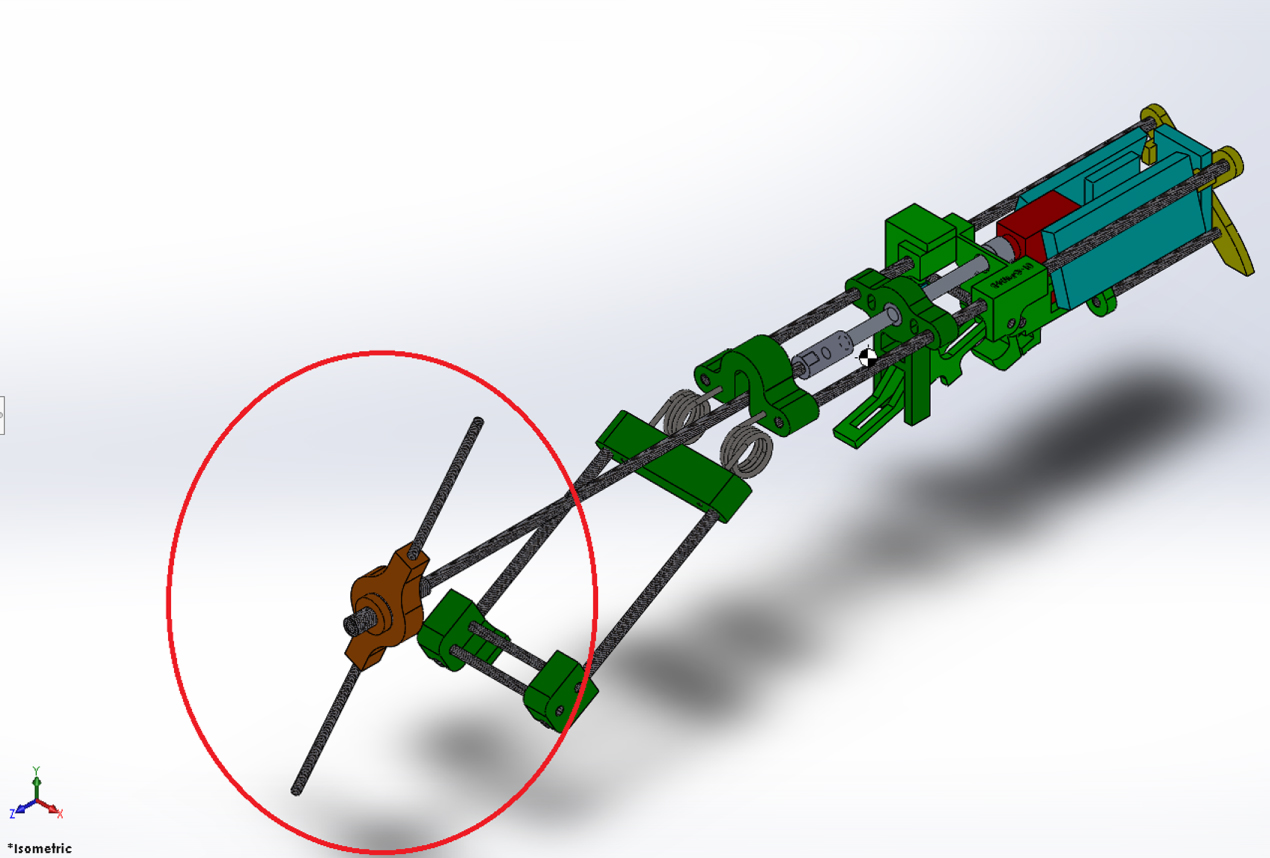
We suggest a novel landing recovery and orientation method, as illustrated in figure 1. A propeller shaped extension made of carbon rods is added as the tail of the robot, connected to a rod through a unidirectional bearing. The mechanism performing the jump is based on a single DC motor charging torsion springs using a wire for torque enhancement. At the beginning, the legs of the robot are fully extended and the torsion springs are loose. Rotating the motor in one direction wraps the wire on the shaft of the motor, pulling the legs toward the body of the robot and charging the torsion springs. At the point where the springs are fully charged, the legs encounter a latch that locks them in place. Since performing a jump requires a quick release of the springs, the next phase is rotating the motor in the reverse direction until the wire is completely loose, and only then releasing the springs so that the wire or the motor do not offer any resistance to the release motion. This is performed using a mechanism that releases the latch once the wire is completely loose. A more detailed description of the jumping mechanism was presented in [8]. In order to add the suggested flip and turn mechanism utilizing the same motor, we take advantage of the length of wire we have between the point where the legs are latched to the robot's body and the release of the latch. Essentially, after the latch locks the legs, the motor rotates to release the wire, and only when the wire is completely released, the latch releases the legs to perform the jump. So, in the range where the wire is not completely released but the legs are locked, rotating the motor does not affect the jump as long as the wire is not completely released. At this stage, we may rotate the motor and release or pull the wire, but nothing else happens. An extension to the motor shaft was added, and the propeller shaped tail is attached to it by means of a unidirectional bearing. When the wire is released, the motor rotates in a direction where the bearing does not transfer the motion to the propeller, thus the propeller does not rotate. Before we reach the point where the latch is released, turning the motor back in a motion that wraps the wire back on the shaft, rotates the propeller. When the propeller hits the ground, the reaction force creates a counter torque on the body of the robot rotating it. This action is like a person lying down on the floor using his hand to push down on the floor in order to flip himself. This way, flipping is accomplished. The flipping operation is illustrated in figure 2.

Figure 1. Schematic drawing of the jumper illustrating the propeller-shaped tail extension in a red circle.
Download figure:
Standard image High-resolution image
Figure 2. Schematic drawing of the flipping order of the jumper: 1—The robot is upside down. The propeller starts rotating. 2—The propeller starts pushing against the ground. 3—The propeller starts raising the robot above the ground. 4—The propellet's push causes a reaction from the body of the robot, and the robot's body starts rotating in the opposite direction.
Download figure:
Standard image High-resolution imageSince the width of the propeller is greater than the width of the robot, the flipping is not cylindrical but conical, thus creating a change in the orientation of the heading of the robot. This operation can be repeated until the robot reaches the desired orientation. The rotation, or turning operation is illustrated in figure 3.

Figure 3. Schematic drawing of the turning order of the jumper (from two perspectives): 1—Original orientation. The propeller starts rotating in the direction shown. 2—Continue rotating the propeller. Propeller starts rising above the ground. 3—Propeller moved past highest point and the robot drops in a rotated position. The angle α depends on the length of the propeller.
Download figure:
Standard image High-resolution imageOnce the desired orientation is reached, all that is left is to complete the release of the wire and execute the next jump. A schematic flow-chart illustrating the operation sequence is shown in figure 4. After the robot jumped and fell back down to the ground, the preparations for the next jump begin. The first step is loading the springs and closing the robots legs. After the legs are closed and held by the latch mechanism, the accelerometer readings indicate whether the robot stands on its feet or not. The program continues to the next step rotating the robot to the desired orientation. If the robot does not stand on its feet, the wire is released by turning the motor CCW for a predetermined period of time and then the motor starts operating CW for a short periods of time, until the robots stands on its feet. The next step is to rotate the robot until it reaches the desired heading. This step also uses the procedure of turning the motor CCW to release the wire and then operating the motor in CW bursts causing the propeller shaped tail to rotate the robot. This operation can repeat a few times until the magnetometer readings indicate that the robot points towards the desired direction . Once the robot reaches the required heading with a certain tolerance, the accelerometer reading indicates whether its on its feet or not. If the robot stands on its feet than the next jump is triggered, otherwise the algorithm for flipping the robot on its feet starts again. To execute jump, the motor will operate CCW to release the full length of the wire. Once the wire is fully released, the latch mechanism releases the legs and the robot jumps. The motor stops working once an acceleration pulse is detected indicating that the robot jumps. This jumping procedure repeats as long as the robot gets jumping commands from a command station. This approach allows giving the robot flipping and turning abilities without adding another motor to the system, accomplishing all functions utilizing a single motor. Thus, utilizing a single motor, the robot can charge the springs, hold them charged, flip itself, re-orient itself and finally, release the springs for the next jump. The overall concept of the robot is to allow sequential jumps so that it can cover an area while maintaining a high enough jump to allow overcoming obstacles such as rocks and boulders or holes and pits in the ground. The robot uses the propeller-shaped tail extension in order to flip itself back on its feet and orient itself for the next jump after the landing. One should keep in mind that unlike the original version of the robot [8], where the design goal was maximizing jump height, in this version, the main goal is the ability to perform a series of directed jumps. Maintaining a significantly high jump is still important since it allows overcoming obstacles, but a reduced jumping height (comparing to the 3.5 [m] jumps in [8]) is desired because it allows for jumping in enclosed spaces (such as indoors or inside mines and caverns), and it significantly reduces the impact forces on the robot's structure, mechanisms and electronic components upon landing. Thus we aimed for jumps of 80–120 [cm] high.

Figure 4. A flow chart depicting the consecutive jumps sequence
Download figure:
Standard image High-resolution imageA detailed schematic illustrating the various components of the robot and its sub-mechanisms along with basic dimensions is shown in figure 5. The actual robot constructed is shown in figure 6, and its materials, manufacturing and assembly methods are similar to those presented in [8, 14]. Its weight is 43–46 [gr], depending on the half-span of the propeller. Since the design of the rotating mechanism relies on a unidirectional bearing, rotation can only be achieved in one direction. In addition, the rotation motion occurs in bursts of torque since the motion due to the shape of the robot is not continuous. Thus, the length and amount of the torque bursts control the overall orientation change of the robot. On top of that, since the rotation of the robot relies on the conic shape of the encapsulating envelope of the robot, the length of the propeller (the half-span), also affects the orientation change per burst. This means that in order to perform a desired orientation change, one must understand the limits of the rotation process. The orientation accuracy depends on the ability to create a small orientation change per burst. Due to this, we desire to obtain a relation between the half-span and burst duration to the orientation change. This information will not only help determine the accuracy of the orientation, but is also required in order to know when to stop the reorientation algorithm, since overshooting a desired orientation means performing a whole new circle of motion due to the unidirectional property of the orientation mechanism (this process was performed experimentally). The mechatronic design of the robot includes an IMU comprising three accelerometers, three gyroscopes and a magnetometer, RF communication card for receiving commands from the base station and a LiPo Battery as an independent power source. Thus the robot is completely autonomous. It is capable of receiving a set of orientations for a sequence of jumps, and perform them autonomously, reorienting itself between each two consecutive jumps.

Figure 5. Side view illustrating dimensions in [mm] and components of the jumping robot with flipping and turning abilities. The additional propeller shape extension is circled
Download figure:
Standard image High-resolution image
Figure 6. The Jumper-Turner robot constructed for the experiments
Download figure:
Standard image High-resolution image3. Experiments
First, validation of the flipping ability is straight forward and requires no quantitative measures. It was verified visually that the robot flips to its feet within a single, relatively long continuous burst. The quantitative experiments, in addition to validating the proper operation of the jumper-turner robot's mechanisms, were designed to obtain a relation between the half-span of the propeller, the pulse duration and the achieved orientation as stated in the previous section. These two parameters are different in nature. The half-span is a design parameter, and once it is set for a specific robot, it cannot change during operation. The pulse duration on the other hand, is a parameter that can be controlled and changed during a mission, between two different jumps and even during a single orientation change session.
3.1. Experiment setup
Two types of experiments were performed. First visual-qualitative experiments showing the ability of the robot to flip back on its feet using the mechanism, and verifying that indeed the robot performs multiple jumps in the general desired direction autonomously. The quantitative experiments were done using fast cameras (GOPRO Hero 5, 240 fps, and Panasonic 4k, 50 fps) and the video tracking software 'Tracker' to follow the rotation of the robot. Two variables were changed during the experiments. First the half-span length of the propeller was given a range of lengths between 60–90 [mm]. For each half-span, various pulse durations were used, in the range of 50–250 [ms]. For each combination of half-span and pulse duration a set of 15 experiments was performed. The experimental layout is shown in figure 7. The robot (highlighted) is lying on a level hard surface with a compass sketch, heading in the 0 orientation. The motor is operated in bursts of a certain duration. Each experiment was conducted through 20 bursts. The orientation is tracked via two cameras (highlighted in figure 7), one giving a top view, and another giving a side view. Thus the orientation is measured after each burst. This was performed using two half-span lengths of 60 and 90 [mm], and burst durations of 50, 150 and 250 [ms]. Each experiment was repeated 15 times for a total of 90 experiments. The orientation control experiments were digitized, and a curve was fitted to each set of experiments, showing orientation on the vertical axis versus number of pulses on the horizontal axis. Thus, the discrete nature of the experiments was given a continuous representation for the purpose of obtaining meaningful conclusions.

Figure 7. Experimental setup. Cameras are highlighted in red. The robot marked purple.
Download figure:
Standard image High-resolution image3.2. Qualitative experiments
The algorithm shown in figure 4 was tested qualitatively both on even and uneven surfaces. The goal was to obtain visual verification that the suggested algorithm and mechanism work together such that the robot indeed performs a sequence of autonomous jumps. While the clear results were positive, and indeed the robot was able to perform a sequence of jumps in approximately the proper directions, a drawback of the mechanism was observed. Since the mechanism relies on a unidirectional bearing, it is capable of rotating only in one direction. Thus, overshooting the desired direction may result in the need to rotate the robot along a time and energy consuming almost full circle. Thus, it is necessary to obtain a quantifiable measure as to the rotation increments the robot is capable of, so that the stopping condition for the rotation algorithm can be set. Furthermore, smaller increment means more accurate orientation. Thus, quantitative experiments were conducted to obtain a good estimate of the orientation resolution, and an understanding of the parameters affecting it.
3.3. Orientation experiments
The goal of the orientation experiments is evaluating the effects of the half-span of the propeller-shaped tail, and the duration of the pulses on the orientation change per pulse. This is important since the orientation control is unidirectional. That is, we can only change orientation in one direction and only in discrete values. Thus, orientation accuracy is limited by the discrete orientation change per pulse, and the control algorithm must take into account that overshooting the desired orientation means the robot is forced to complete an entire circle in order to 'go back' one orientation increment. An example of such a plot is represented in figure 8, for the case where the half span is 60 [mm] for 50 [ms] pulses. In this plot we see the orientation in degrees on the vertical axis plotted against the number of pulses on the horizontal axis. Although fifteen experiments were performed for this configuration, the plots show points for only five experiments for purpose of clarity of presentation. The error crosses and the curve matched were performed for entire set of experiments. For the case presented in figure 8, the orientation error is ±4.3°. This linear curve is a continuous function relating the orientation change as a function of the number of 50 [ms] pulses. Although the number of pulses is a discrete variable, a continuous function is useful in the sense that its derivative yields the orientation change per pulse, which is the resolution of the orientation control of the robot. A summary of all matched curves of the six combinations of half-spans and durations is presented in figure 9.

Figure 8. A linear curve representing the orientation progress as pulses of 50 [ms] are applied sequentially to a robot with 60 [mm] half-span.
Download figure:
Standard image High-resolution image
Figure 9. Linear regression curves for all half-span and pulse duration combinations.
Download figure:
Standard image High-resolution imagefigure 9 clearly illustrates that longer pulse durations stand for higher slopes indicating higher orientation increment per pulse, which is the dominant factor of the two examined variables. It is also clear that the shorter half-spans yield higher slopes than the longer half-spans for a given pulse duration. While pulse duration may be controlled and varied during operation of the robot, the half-spans, once determined cannot, of course, be varied during operation, and are a design parameter. Thus, designing the robot with higher half-span would give us a lower slope and therefore better turning resolution.
3.4. Experiments conclusions
Based on these results, a bilinear curve was matched to obtain a relation between orientation and both half-span and pulse duration analytically. This curve was evaluated using the six linear regression curves obtained from the experiments described earlier. The obtained relation is

where θM is the orientation in degrees, Δtp is the pulse duration in milliseconds, L is the half-span in millimeters and N is the number of pulses. The coefficients α, β, γ and λ are the experimental model parameters. In our case, the following parameters were evaluated:

Based on these parameters, and to verify the ability of this formula to predict results of untested cases, a new arbitrary half-span was created at L = 67 [mm], and a set of fifteen repeating experiments was performed for the pulse duration of 50 [ms]. Figure 10 shows both the predicted curve and the matched curve for the experimental results. It is clear that the curves are almost completely identical, supporting the validity of the analytical curve-matching as a design tool for the jumping robot orientation control algorithm.

Figure 10. Experimental versus Prediction (dashed) curves for half-span of 67 [mm] and pulse duration of 50 [ms]
Download figure:
Standard image High-resolution image
4. Conclusions and future work
The goal of the added mechanism is to allow a jumping robot to perform autonomous consecutive jumps. This was done using the suggested propeller-shaped mechanism. The mechanism was shown, using qualitative pass/fail tests to be able to perform the flipping task. Once the robot is back on its feet, it may need to reorient itself so that the jump will be in the required direction. The same mechanism is used to perform this task, however, the rotation increments depend on two parameters: propeller length and pulse duration. These rotation increments determine when the rotation sequence should be stopped, since rotation is possible only in one direction. Experiments were performed to determine the effects of these parameters. A reorientation algorithm was presented, and quantifiable measures for determining the turning resolution were established quantitatively. A bilinear analytical expression for evaluating the orientation change was established experimentally, and was shown to predict results on an untested case. The resolution of the orientation change is determined by the slope of the orientation-pulse number curve, helping to identify the exit condition of the orientation algorithm, since the orientation mechanism is unidirectional. The analytical expression may be further utilized to enhance the control algorithm such that variable pulse durations may be used in the same turning sequence so that when the robot is far from the desired orientation it can use longer pulses and shorten their duration once getting closer to the desired orientation. One must keep in mind that the purpose is not to obtain an accurate orientation, rather, to obtain an estimate or a range for the orientation change per pulse so that an approximate direction for the next jump will be achieved. Since the robot is designed to operate outdoors and not in a laboratory setting, exact measures cannot be employed. The main advantage of the maneuvering concept of this robot over controlling the direction of the jump while airborne or by leaping in a desired direction is that this concept allows recovery from unexpected landing occurrences. These may occur not just because of the jump process, but also because of the unpredictability of the landing surface itself—even when the landing is "soft", the robot may land on a slope or a stone or anything else that might cause the pose of the robot to be wrong. The suggested method presented here can overcome such perils, whereas methods that rely on controlling the jump to achieve a desired landing pose cannot compensate for such scenarios. Further work includes experimentation on the effect of various surface types on the orientation resolution and establishing a way to determine the surface type autonomously so that a correct estimation will be adopted for each case.