
Abstract
Soft pneumatic bending actuators generally produce a bending deformation through pressurization, but the force they produce diminishes significantly throughout the deformation for a given pressure level. This is useful to produce a controlled motion, but sensors are required to enable force control of the actuator throughout this motion. This paper introduces the use of an inflatable L-shaped prism as a soft actuator that has a constant equilibrium angle and produces a fairly constant force throughout most of its actuation range. This combination of characteristics makes the actuator ideal for applications where an easily controllable force without the use of sensors is required or preferable. However, it is unsuitable for applications where motion control is necessary due to its constant equilibrium angle. The effect of different geometric parameters and materials were tested, and it was found that this actuator could produce a blocked force of up to 13 N at 80 kPa and could maintain this force throughout most of this range of motion. This actuator concept was then used to build a three-fingered soft exoglove capable of grasping a wide range of objects.
Export citation and abstract BibTeX RIS
1. Introduction
Recent studies on soft robots and structures have shown their large potential for applications requiring interaction between robots and humans which stems from their inherent compliance with their environment [1–3]. However, the most widely used soft pneumatic actuator designs make use of polymers which require long curing times, the weight of the polymer can be a problem when using multiple actuators, and their force reduces significantly throughout the motion for a fixed pressure. The equilibrium angle of these actuators then varies with both position and pressure and the force produced diminishes gradually to zero at the equilibrium angle [4]. If implemented into a soft exoglove, the gripping force would depend on both the position and the pressure such that force or displacement sensors would then be required to control the gripping force, which increases system complexity. A pneumatic soft bending actuator whose force depends mainly on pressure for a given actuation range could simplify the design and implementation of soft actuators into wearable technology.
Early soft pneumatic actuators took the form of pneumatic artificial muscles (PAMs) that can produce extremely large linear forces using pressures up to 800 kPa and can contract by up to 40% of their length by transforming the lateral expansion of a tubular structure made from rubber into a linear contraction [5–8]. However, these actuators have limited potential for producing bending deformations as their basic design limits the capability to produce large bending deformations. Varying the materials of the structure or using diverse methods to add anisotropic properties to the structure have enabled polymer-based soft pneumatic actuators to produce bending deformations [9–11]. This kind of actuator has been used for robots such as crawling robots [12], miniature and human-sized hands [13, 14], in exogloves [15–17], explosion-powered jumping robots [18], swimming robots [19, 20], and chemical-reaction powered octopus robot [21]. Although very flexible in both implementation and use, their structures require large volumes of polymers which adds to their weight, the displacement of large volumes of air at pressures up to 300 kPa to fully actuate them, and their force diminishes significantly with an increase in bending angle for a given pressure.
Replacing polymers by thin films such as plastic films or technical textiles allows the fabrication of extremely lightweight inflatable actuators with an even wider design space. Tendon-actuated inflatable jointed actuators have been investigated for safe human-robot interaction in an elbowed robot [22, 23], but these actuators rely on external motors for actuation. Folded inflatable tubes have been used to create the rotation of a rigid joint [24], as an inflatable member for stiffness control between the joints of a robotic arm [25], and as a rotary elastic chamber actuators to create an entirely soft robotic joint [26]. Pleated films have been used to realize bending and twisting actuators using the anisotropic expansion of the pleats [27–29], pouch motors consisting of inflatable flat rectangular pouches have been used to produce linear and bending motions using rigid constraints [30, 31], and these pouch motors have been used as a gait rehabilitation device for rats [32]. Heat sealed inflatable film structures called aeroMorphs capable of changing shape for user interaction have been developed based on indentation of the film which produces anisotropic inflation [33], and the same group developed bending film actuators making use of sealed vertical features on a flat pouch called Printflatables which realizes anisotropic expansion around a joint [34]. Inflatable bending actuators using stretchable films located inside of extensible or partially extensible chambers have been developed [35, 36]. However, most existing polymeric and film-based soft actuators' bending force reduces throughout the deformation as their deformation produces the largest change in volume in the early part of the bending deformation.
In this work, we present an actuator consisting of a simple L-shaped inflatable structure in the shape of a rectangular prism with a built-in bent angle along its length which serves as a rotation point around which a deformation of the actuator produces a restorative force. The main novelty of this actuator is that it can produce a bending force that depends mainly on the pressure within the actuator when it is deformed from its freely inflated bent state whereas the surveyed soft bending actuators' bending force depends on both position and pressure. Also, the equilibrium point of the actuator does not change with pressure. This characteristic can be used to apply an easily controllable force on a jointed structure whose range of angle ranges from the flat position to that of the built-in angle of the actuator. This work will show how this design can be modeled to predict its force, the importance of its different design characteristics, its actuation characteristics, and how it can be implemented as a lightweight, low-cost and simple soft exoglove.
2. Design and model
2.1. Design and manufacturing
The actuator design consists of a rectangular prism with a built-in bent angle along its length and is composed from an airtight material (figure 1(a)). The actuator shown in this figure is made from thermoplastic polyurethane (TPU) film with a thickness of 200 μm. Unhindered, inflation of the actuator will have the actuator assume the shape of its designed prism with a given built-in bent angle θ0, and a deviation from this built-in bent angle will cause a reduction in the volume of the actuator. As inflatable elements tend to produce a restorative force in order to return to its maximal volume, the actuator creates a force to return to its built-in bent angle which is its point of maximum volume. The force produced by the actuator is fairly constant due to the rate of change in the volume of the actuator during the deformation fairly constant for all angles. Although the volume could be twisted or deformed in any direction, the target deformation from its free inflated state is one where an object is meant to be attached on the surfaces on the inner portion of the built-in bent angle's surface and where the actuator is deformed towards the direction that would make this surface flat (figure 1(b)).
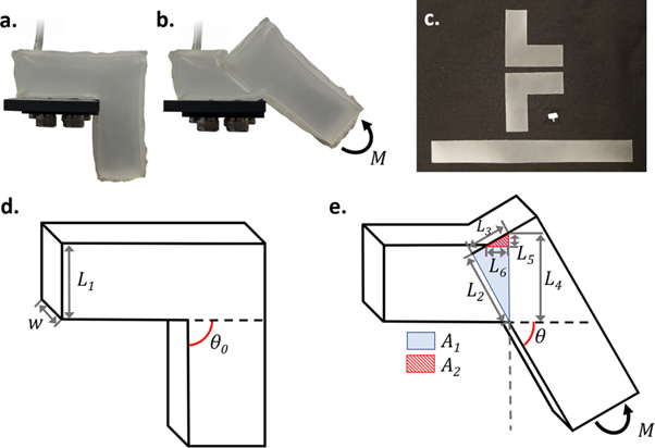
Figure 1. (a) Undeformed shape of the actuator, (b) deformed shape of the actuator, (c) cut patterns for manufacturing of the actuator, and (d) dimensions of the undeformed and (e) deformed shape of the actuator.
Download figure:
Standard image High-resolution imageAs demonstrated later in this paper, the particularity of this actuator is that the force produced by the actuator is fairly constant throughout a significant range of motion for a given pressure. Another important particularity of this actuator is that the equilibrium angle does not depend on pressure such that actuator needs to be deformed from its initial equilibrium shape to produce a force. This means that position control of the actuator using pressure for feedback would not be possible. However, the volume of air within the actuator can be used for position control given a certain load onto the actuator although this is harder to implement. Alternatively, a second chamber could be used to assist in control of the position for applications requiring it. But this does not prevent it from being usable as an exoglove where having an equal assistive force applied on all fingers is more important for grasping than controlling their position.
The ideal material for this actuator is one that is lightweight and does not stretch but can be freely deformed without applying significant force as the deformation of the actuator and its change in volume throughout this deformation are what gives the actuator its intended properties rather than any stiffness of the material. Also, a stiffer material would hinder the actuator from being easily bent at low pressures. The actuators manufactured in this paper are made from TPU film with a thickness of 200 μm, and from TPU film backed with a polyester/nylon fabric. The actuators are manufactured by making a pattern of the flat structure of the actuator and cutting it using a laser cutter (figure 1(c)), then bonding together the pieces on their edges by thermal bonding using an impulse sealer.
2.2. Quasi-static model
The deformation of the actuator causes a crease across the cross-section of the thinner side of the actuator. Only the change in volume of the actuator needs to be considered in order to develop a quasi-static model of the actuator if the force required to bend the walls of the actuator is minimal. The change in area ΔA of the actuator can be calculated by calculating the area of triangle A1 and deducting the area of triangle A2 as

The areas can be calculated based on the lengths L1 to L6 (figures 1(d)–(e)).


The length L2 is equal to the height L1 of the actuator and the lengths L3, L4, L5 and L6 can be calculated based on the bending angle θ as


Using equations (1) to (6), the derivative of the change in area ΔA as a function of θ can then be calculated and simplified as

The moment M produced by the actuator as a function of θ can then be calculated using the principle of virtual work as

Where P is the inner pressure of the actuator and V is the volume of the actuator. Assuming the actuator is a prism with a constant width w, the moment produced as a function of θ can be calculated as

The shape of this curve is relatively flat following a slight decrease near the zero angle and produces a sustained moment until the equilibrium angle which is due to the relatively constant change in volume with a change in angle θ. This equation is only valid for the range of θ ranging from the flat position (θ = 0) to the designed initial bent angle of the actuator (θ = θ0). Bending in the other direction causes a rounding of the surfaces rather than an overlap in the volume which would need a separate model and is not part of the intended motion range of the actuator in this work.
2.3. Method
To measure the deformation force of the actuator, one side of the actuator is held to a surface whose angle can be changed manually and the other side is pushing against a force-torque sensor (RFT40-SA01, Robotous). The pressure within the actuator is controlled using an electro-pneumatic regulator (ITV1030, SMC) supplied by an air compressor (MD75/250, Bambi).
3. Results
3.1. Parametric study
A base actuator with a cross-section of 20 mm in width by 20 mm in height and a designed bent angle of 90° is taken as the basic actuator where each segment has a length of 40 mm. Variations of the base actuator are done in terms of the width of the actuator, height of the actuator and designed bent angle. The moment produced by the actuator is measured at different pressures ranging from 8 kPa to 20 kPa at angle increments of 15° from 0°, which is the flat position, to the designed bent angle of the actuator. The actuators in this section are made from TPU with a thickness of 200 μm.
3.1.1. Effect of the actuator's width
Three actuators were built with widths of 15, 20 and 30 mm and were tested using the previously defined conditions to test the effect of the width on the performance of the actuator (figures 2(a)–(c)). The results show that the force produced by the actuator is proportional to the pressure within the actuator and that the force is fairly constant throughout the motion. The actuators with widths of 20 and 30 mm have a negative force at their designed equilibrium angle of 90° which is due to unbending of the actuator caused by stretching of the materials and rounding of the inner surface of the actuator. Results also show that wider actuators produce a large force than thinner ones due to the larger change in volume resulting from a rotation of the actuator, but that thinner ones appear to minimize the unbending of the actuator due to less rounding of the inner surface of the actuator.

Figure 2. Blocking force versus actuator angle for actuators with a height of 2.0 cm and a width of (a) 1.5 cm, (b) 2.0 cm, and (c) 3.0 cm.
Download figure:
Standard image High-resolution imageThere is good agreement between the experimental results and the results predicted using the proposed numerical model. Some differences can be seen in that the experimental results near the equilibrium angle display little difference with a change in pressure which could be due to the way the material deforms at this position. The model represents a simplification of the deformation of the actuator that does not consider some of the smaller deformations of the film that are required to allow for the rotation of the structure around its rotation point, but it still allows to accurately predict the force of the actuator.
3.1.2. Effect of the actuator's height
Three actuators were built with heights of 15, 20 and 25 mm and were tested using the previously defined conditions to test the effect of the height on the performance of the actuator (figures 3(a)–(c)). It is to be noted that the actuator with a height of 20 mm is the base actuator and the same actuator as that with a width of 20 mm in the previous section. Results show that an increase in height of the actuator results in an increase in the force produced by the actuator. As in the previous section, the actuators produce a relatively constant force for most of their intended range of actuation, but their force drops as the angle gets closer to the designed bent angle of the actuator. This is also due to the unbending effect, but the height of the actuator does not appear to affect the unbending of the actuator. Based on these results, increasing the height of the actuator is a good solution to increase its force if the design is able to accommodate this increase in height of the actuator.
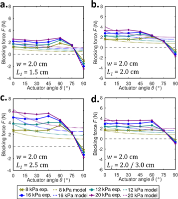
Figure 3. Blocking force versus actuator angle for actuators with a width of 2.0 cm and a height of (a) 1.5 cm, (b) 2.0 cm and (c) 2.50 cm, and (d) for an actuator with uneven heights of 2.0 and 3.0 cm.
Download figure:
Standard image High-resolution imageThe previous actuators have had the height of both segments of the actuator equal. An actuator with a height of 20 mm for one segment and 30 mm for the other segment was tested in similar conditions as shown in figure 3(d). Results show that this actuator deforms on the segment with the smaller height and that this actuator produced a force similar to the actuator with a 20 mm height rather than the actuator with a larger height. This shows that such a joint will produce a force corresponding to the segment with the smaller height as the actuator will favor forming the crease on the side where a smaller change in volume occurs.
3.1.3. Effect of the actuator's designed bent angle
Previous experiments focused on the basic dimensions of the actuator and found that unbending causes the actuator to have small or negative force near its designed bent angle. Actuators with designed bent angles of 30, 60, 90° and 105° were manufactured to test the effect of the bent angle on the unbending of the actuator (figures 4(a)–(d)). Actuators with designed bent angles over 105° were difficult to manufacture due to the limitations of the impulse sealer used but could possibly be manufactured using different manufacturing methods. All of the tested configurations showed unbending for a range of 15 to 30° over its designed bent angle and a negative force at the designed bent angle, which shows that the extent at which unbending occurs is a function of other factors. The actuator should thus be designed to have a larger designed bent angle than the intended range of actuation of the actuator.

Figure 4. Blocking force versus actuator angle for actuators with a designed bent angle of (a) 30°, (b) 60°, (c) 90°, and (d) 105°.
Download figure:
Standard image High-resolution image3.2. Effect of material
Previous experiments were tested with a TPU film with a thickness of 200 μm which is slightly extensible within the range of pressure applied to the actuator. It was observed that the actuator deviated from its designed bent angle under pressure even in the absence of any external loads. The effect of pressure on the deviation from the designed bent angle of 90° was measured for TPU films with thickness of 50, 100 and 200 μm, TPU backed with woven nylon (210D) as well as TPU backed with knitted polyester (20D) which was tested in both longitudinal and transversal orientations for the inner portion of the actuator as this material is anisotropic (figures 5(a)–(f)). All actuators were made with the same dimensions as the basic actuator of the previous sections. It can be seen that all actuators display an unbending behavior that is proportional to the pressure within the actuator (figure 5(g)). Thinner TPU produces significant unbending that is equal to the TPU-backed polyester positioned in the direction that produces more longitudinal stretching. The actuator made from TPU-backed polyester positioned in the transversal direction had significant expansion of the inner and outer section of the actuator and its initial bending angle shifted rapidly and then steadied. Thick TPU actuators and TPU backed with Nylon displayed a minimal amount of unbending.
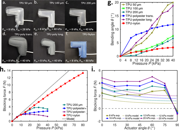
Figure 5. (a) Initial bending angle versus pressure and (b)–(h) blocking force versus actuator angle for actuators with different materials, and (i) blocking force versus actuator angle for a TPU-Nylon actuator.
Download figure:
Standard image High-resolution imageThe blocking force versus pressure for the actuators made from TPU-backed fabrics and for the actuator made from TPU with a thickness of 200 μm were tested at a bending angle θ of 45° up until the actuators displayed excessive leaks or failed. Although all actuators had similar performance at very low pressure, the results show that the TPU-backed nylon actuator performed best at the all pressures and was also capable of sustaining larger internal pressures such that its maximum force exceeded 13 N at 80 kPa (figure 5(h)). Other materials began to stretch beyond their elastic limits and exhibiting leaks at higher pressures which was not considered by our numerical model. The TPU actuator with a thickness of 200 μm had a better performance than both TPU-backed polyester actuators. The performance of the TPU-backed nylon actuator was then measured for different bending angles and pressures (figure 5(i)). This actuator exceeded the performance of the actuator made from only TPU and also showed a more sustained force throughout the entire motion. The stiffness of the material also provided an extra force that could be responsible for the actuator producing a blocking force larger than the model. Finite element analysis could be used to further predict the performance of different materials and to predict the location and effect of plastic deformation of the materials, but the location and severity of leaks may hard to model using either numerical or analytical methods.
3.3. Comparison with other soft bending actuators
To better demonstrate the difference in properties between the proposed actuator and existing actuators, its performance was compared to two representative soft bending pneumatic actuators. The first is a soft fiber reinforced bending actuator as modeled and tested in previous works by Wang et al using an actuator with a rubber body, woven fiberglass strain limiting layer and Kevlar fibers wound around the body of the actuator which has a width of 16 mm (figure 6(a)) [4]. This soft bending actuator design using these materials is one of the most common soft bending actuators made from polymers due to its good performance. It can be seen that the point of zero blocking force varies significantly with an increase in pressure such that certain bending angles may not be reachable at low pressures, and the force produced for a given pressure also decreases throughout the motion. This is due to the significant work required to stretch the matrix throughout the deformation and due to the relation between the change in volume and the change in bending angle. The proposed actuator can produce a nearly equal maximum blocking force using a much lower pressure, 20 kPa versus 241 kPa, with a similar width, 20 mm versus 16 mm. However, the change in equilibrium point is what allows the polymeric actuator to easily control its bending angle with or without a load but requires additional sensors to control the force produced by the actuator.
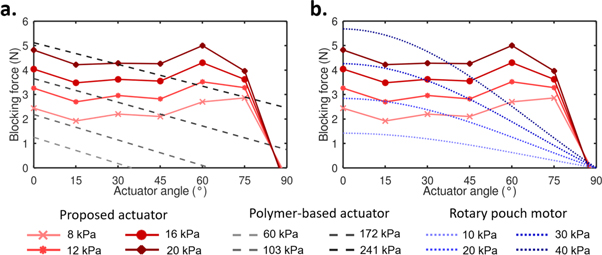
Figure 6. (a) Comparison of the present actuator with a polymer-based actuator, and (b) comparison of the present actuator with a rotary pouch motor.
Download figure:
Standard image High-resolution imageThe second actuator used for comparison is a film-based rotary pouch motor as tested and modeled by Niiyama et al with a width of 75 mm, a length of 25 mm, and using a moment arm of 50 mm as in the actuators tested in this paper (figure 6(b)) [30]. The equilibrium point of the rotary pouch motor without an applied load does not depend on pressure as the material of the pouch motor does not need to stretch, which is a property that most inflatable actuator have including the proposed actuator. However, the force produced by this actuator reduces significantly throughout the motion due to the relation between the change in actuator angle and the change in volume of the pouch. The proposed actuator can produce a nearly equal maximum blocking force using a slightly lower pressure and a significant smaller width while maintaining this force throughout the entire motion. The rotary pouch motor would be able to realize position control using pressure feedback due to the change in bending force produced throughout the motion for a given pressure. But force control could not be done based only on pressure as the bending force would depend on both position and pressure, unlike the proposed actuator. These two examples demonstrate how the properties of the proposed actuator are significantly different from existing actuators and how this affects their operation.
3.4. Inflatable soft exoglove implementation
As the concept proposed in this paper is able to produce a constant force at a constant pressure throughout most of the range of motion between the flat position and a designed bent angle, it is ideal for implementation as a lightweight exoglove with simplified control as the force produced by the actuator can be predicted using only the pressure within the actuator. A prototype of such an exoglove is presented in this section. Based on the previous analysis of the effect of the material on the unbending angle and the maximum pressure, the nylon-backed TPU film was used for the structure of the actuators of the exoglove. The exoglove has three fingers where the actuator for the thumb has two bent angles for the metacarpophalangeal and the distal interphalangeal joints and the actuators for the index and middle fingers have two bent angles each for the metacarpophalangeal and the proximal interphalangeal joints (figures 7(a)–(b)). Actuation for the distal interphalangeal joint is omitted as it moves with the proximal interphalangeal joint and could interfere with objects or with the thumb's actuator (figures 7(c)–(d)). The actuators for the index and middle fingers have a width of 20 mm and a height of 20 mm while the thumb has a width of 20 mm and a height of 30 mm. The widths were chosen based on the width of the fingers while the heights were chosen to have a higher force on the thumb to have a better force equilibrium while performing power grasps. The metacarpophalangeal and the distal interphalangeal joints for the thumb have a designed bent angle of 50° and 75°, respectively, and the metacarpophalangeal and the proximal interphalangeal joints of the other two fingers of 100° and 110°, respectively, to be able to produce a power grasp capable of provided grasping assistance for a wide range of objects.

Figure 7. (a) Manufactured shape of the actuators used in the soft exoglove, (b) cut pattern of the actuator, and (c) unpressurized and (d) pressurized shape of the actuator of the index finger of the exoglove.
Download figure:
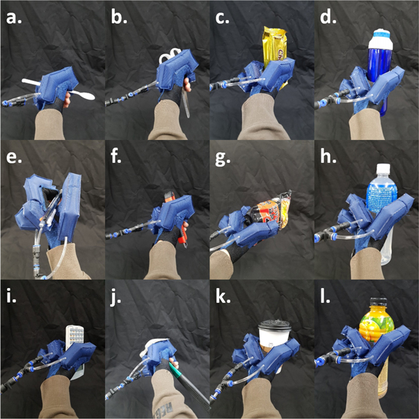
Standard image High-resolution imageAs the current design and implementation of the exoglove is made to apply a similar force to all joints of all three fingers, the exoglove is intended to be used for either pinching or for power grasping objects. The exoglove was tested with a wide range of objects ranging from objects requiring pure pinching grasps such as pens or spoons to objects requiring power grasps such as bottles (figures 8(a)–(l)). The actuator was capable of aiding in grasping all of these objects at a pressure of 40 kPa regardless of the size of the object since the force produced does not depend significantly on the position of the actuator. Furthermore, the exoglove weighs only 46.8 g (25.6 g without tubing), which is amongst the lightest of the surveyed exogloves. The pneumatic system consists of a small pump (BTC-PDMC, Parker) weighing 128 g, which does not contribute to the weight felt by the hand as it can be located far from it. It is to be noted that although the exoglove was capable of assisting in grasping scissors, it would be unable to assist in using these scissors due to the volume of the actuators preventing the insertion of the fingers into the handles of the scissors. The actuator may have similar issues with other tools requiring insertion of the fingers into handles or holes, but the volume did not cause issues during either pinch or power grasping.
Figure 8. Exoglove grasping (a) a spoon, (b) scissors, (c) a snack, (d) a water bottle, (e) a pen, (f) a cutting knife, (g) instant noodles, (h) a sports drink, (i) a remote control, (j) a hammer, (k) a cup of coffee, and (l) a bottle of juice.
Download figure:
Standard image High-resolution image
4. Conclusion
The actuator concept proposed in this work is made from similar materials to many existing soft pneumatic actuators, but its actuation characteristics are quite different. The force produced by this actuator at a given pressure is fairly constant for a wide range of motion and has a stable equilibrium point. However, while other actuators focused on pressurization of the actuator to change the equilibrium shape of the actuator and to produce a force against an object, the present actuator needs to be deformed from its initial equilibrium shape to produce a force. This can be detrimental when used as a soft gripper since the fingers may need to move away from the object before grasping it, but this property does not prevent it from being usable as an exoglove where the finger can move away from the object but may need additional force to produce a strong grip. The stable equilibrium point helps in grasping objects of unknown dimensions or shape since simply raising the pressure to a certain level will produce a known grasping force without requiring sensor feedback.
Many of the surveyed soft bending actuators have higher maximum bending forces than the actuator presented in this work. However, their force diminishes the motion and may not be able to produce significant forces at the joint angles that fingers require to have a full range of motion. The actuator presented in this work is capable of maximum bending forces nearly as large as other commonly used soft pneumatic bending actuators while being able to produce this force even at large bending angles with the same pressure.
The actuator also possesses other characteristics that makes it well suited as an exoglove. The actuator has defined rotation points which can be positioned to correspond perfectly with those of the human fingers. It is much lighter than polymer-based pneumatic actuators or actuators using motors with rigid mechanisms. It also does not pose any problems related to tendon routing that tendon-based actuation may encounter when a large number of actuators are used. A pressure of 40 kPa is sufficient to produce a stable grasp on most household objects, which makes the actuator safe and allows it to use small and portable pneumatic systems. Future work will focus on separating the different joints within the actuator, on further validation of its performance using finite element analysis, and on the minimization of the unbending effect.
Acknowledgments
This work was supported by the Technology Innovation Program (or Industrial Strategic Technology Development Program (10080336) funded by the Ministry of Trade, Industry & Energy(MI, Korea) and by the National Research Foundation of Korea(NRF) grant funded by the Korea government (Ministry of Science, ICT & Future Planning) (No. 2018R1C1B6003990).