
Abstract
The objective of this study is to analyze the performance of a blast-proof composite material upon impact loading subjected under blast. The material that is currently being used for blast protection is armored steel. Although it has high strength and toughness its strength to weight ratio is low which limits the applications of armored steel. Hence to overcome this limitation a sandwich composite was considered as an alternative to steel for blast protection. The sandwich composite had the top layer as Ceramic matrix composite to withstand high temperatures, core as a honeycomb structure and bottom layer as polymer matrix composite to stop the core from deforming excessively. The composite was modeled in Abaqus/Explicit and with the help of literature, the blast load was simulated as a triangular pulse in the form of the number of Tri Nitro Toluene (TNT) exploded. The performance of the composite was investigated by analyzing the amount of energy absorbed by the material upon impact and was compared with the performance of armored steel. The results showed that the sandwich composite was able to perform better than or equal to steel up to the explosion of 3 kg of TNT. But beyond 3 kg TNT its performance degrades and becomes lower than steel. Beyond explosion of 3 kg TNT the top layer, Ceramic matrix composite fails which exposes the inner core to the blast environment. As the amount of explosive increases, the core starts to undergo excess deformation and after a certain load, the deformation exceeds the limit of the bottom layer leading to the failure of the polymer matrix composite. Therefore, the proposed sandwich composite performs better than steel within a given working condition but beyond its working condition, its performance degrades resulting in failure of sandwich composite.
Export citation and abstract BibTeX RIS
Introduction
Over the last few decades, considerable attention has been raised on the behavior of structures subjected to blast or impact loading. Due to the recent increase in various terrorist activities all over the world, for the safety of civilians structures should be designed to resist blast loads.
Explosive devices have become smaller in size but more powerful than before, Leading to increased mobility of the explosive material and large damage effects. Usually, the casualties from such a detonation are not only limited to instant casualties which are a consequence of the direct release of energy, but also to structural failures that could result in extensive life loss. Keeping this in mind a better solution for such situations is required to protect the lives of people. Blast loads are dynamic loads that need to be calculated and the structures should be designed by considering these loads to make it blast resistant. One of the objectives of this investigation is to review the works on the effects of blast loading on structures. A composite material was chosen for the design so that the weight of the structure will be reduced almost by half when compared with steel and have better damage tolerance properties. No structure can be designed to resist the explosive loads completely. But the designer could take certain steps to better understand the behaviour of a material under blast load and design to protect the lives of people.
Table 1. Design conditions.
| Explosive | TNT |
| Standoff distance | 0.221 m |
| Type of explosion | Ground burst |
| Type of confinement | Partially confined |
An explosion is a quick and stable compound reaction which advances through the explosive at supersonic speed. This detonation velocity ranges from 6700 m s−1 to 8500 m s−1 for most high explosives. This explosion wave quickly converts the explosives into a hot, thick, and high-pressure gas which is the source of a strong shock wave in air. The pressure close to an explosion front ranges from 18.6 GPa to 33.7 GPa. A time history graph of the blast wave has been provided in figure 1. Just around 33% of the complete explosive vitality is discharged in an explosion. The remaining 67% are all the more gradually discharged into the air as the objects of the explosion combine with air and burn. This has a negligible effect on the properties of the blast wave as it proceeds slower than the blast waves. The blast wave is a shock wave formed by a high - intensity shock front that expands into the surrounding air from the surface of the explosive. As the wave expands the front impinges on the structure in its path and the whole structure is swallowed up by shock pressure [1].
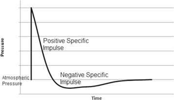
Figure 1. Blast wave pressure-time history.
Download figure:
Standard image High-resolution imageThe material that is currently being used for blast protection is armored steel [2]. All the other materials are either in the prototype stage or concept stage. Although steel has high strength and toughness, its strength to weight ratio is low, For example, the weight of armored steel is about 2.4 tonnes for 2.73 × 1.1 × 0.0315 m plate and literature survey [2] verified that the performance of steel degrades with temperature. Hence we need an alternative for steel which has better strength to weight ratio.
A study by Xiaochao Jin et al [3] describes the performance and advantages of using a sandwich composite for blast protection. A sandwich structure comprises of two high strength plates and a low-density core layer. The main objective of this type of structure is to combine the stiffness and strength of the thin face-sheet and the lighter weight of thicker flexible core to achieve superior material and structural properties. Hence, a sandwich construction was chosen for the composite material.
The top layer of the sandwich composite is a ceramic matrix composite whose matrix is Zirconium diboride and reinforcement is Silicon Carbide fibers. The core is a honeycomb core made of armored steel. The bottom layer is polymer matrix composite whose matrix is Poly Ether Ether Keytone (PEEK) and reinforcement is poly(p-phenylene-2,5-benzobisoxazole) (PBO) fibers.
Temperatures resulting from a blast can reach upto 4000 °C and hence Zirconium diboride (ZrB2), a ultra-high temperature ceramic (UHTC) was considered for the top layer of the composite [4]. Properties such as a melting point of 3246 °C, density of ∼6.09 g cm−3 and high strength made it an ideal candidate to withstand blast loading. Silicon Carbide(SiC) [5] is capable of withstanding thermal shocks primarily due to its superior properties such as higher thermal conductivity, high elastic modulus and moderate coefficient of thermal expansion. PEEK [6, 7] has high plastic toughness and rigidity. It also has excellent corrosion, abrasion resistance, tenacity and tensile strength. It performs well in high temperatures up to 260 °C where heat is a major concern. Advantages of PEEK over metals include tolerance to mechanical and physical stress along with excellent chemical and thermal resistance. PBO [8] is the strongest fiber with a high tensile strength of 5.8 GPa which is 1.6 times that of Kevlar, a tensile modulus of 180 to 270 GPa, Heat resistance up to 650 °C and thermal stability high-performance fibers such as p-aramid, m-aramid, steel fibers, PBI, polyester, etc. These qualities make PBO fiber a good candidate for blast resistant composite material. Sandwich panels composed of conventional steel honeycomb cores are chosen for their performance to impulse loads.
Once the material was chosen, the analysis began by modeling the composites Abaqus/Explicit. Micro-modeling [9] was utilized to model the top and bottom layer and a solid model was utilized to model the honeycomb core. With the help of literature [1], the load was modeled as a triangular pulse and the properties of different materials and their failure criteria were obtained. The composite was analyzed for its behavior under load from different amounts of explosives and its performance was characterized by the amount of energy absorbed upon impact. The composite's performance was compared with steel to find which offers better protection under a given blast.
Analytical study
Determination of blast load
Blast loads are not characterized by any international organization. Hence this topic needs to be explored further as there are no standard procedures to design or evaluate structures which is under a blast load. To do this a fundamental understanding of the blast phenomena as well as the dynamic response of various materials are required. On the other hand, this topic is of interest in military perspective as the important experimental data are restricted to military use. Nevertheless, a number of literatures are available which investigates various methods to characterize a blast load and to analyze a material under a blast load [10]. The TM 5 1300 (1990) manual [1] from the US army was utilized to calculate the pressure forces that impinges on a structure under a blast load with the following configuration.
Figure 2 shows the parameters required to calculate the pressure acting on material due to an explosion. The empirical formulae and experimental data available in the TM 5 1300 (1990) manual was utilized to calculate the pressure behind a blast for a given standoff distance.
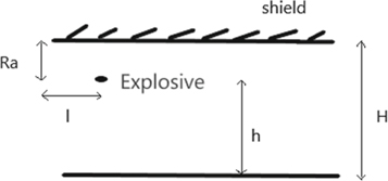
Figure 2. Illustration of explosive setup.
Download figure:
Standard image High-resolution imageThe utilization of cubicle structures or other comparable boundaries with at least one surfaces either adequately frangible or open to the environment will give some level of venting relying upon the opening size. This type of structure will allow the blast wave from an internal explosion to leak out to the surrounding area, thus significantly reducing internal pressure magnitude and duration. Therefore the pressure impinging on a surface can be categorized into
- Shock pressure—The pressure within the containment which is reflected and strengthened.
- Gas Pressure—The pressure associated with gas particle accumulation and increased temperature.
- Leakage pressure—The pressure from the gases that fled through the vents [1].
Since the explosion happens near the ground the effect of temperature is negligible when compared with the effects of pressure. Therefore, only shock pressure was considered and its effect on the structure was analysed.
Figure 3 shows the pressure versus time graph obtained from following the steps in TM 5 1300 (1990) manual. Since the experimental data was limited in the book interpolations and extrapolations was utilized to extend the experimental data for our design conditions.
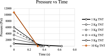
Figure 3. Pressure versus Time plot.
Download figure:
Standard image High-resolution imageFinite element analysis
Finite Element Method was utilized to analyze the response of the sandwich composite under a blast load. The analysis was conducted in ABAQUS explicit. A quarter model was utilized for analysis because of its ease in modeling and assign finer meshes. The behavior of the quarter model was extended to the whole model with the help of the symmetry condition.
Micro-modeling [8] was utilized to model the top and bottom layer. In this approach, matrix and reinforcements are modeled as a separate deformable continuum. This approach could be used when microscopic behavior of individual fibers and their interaction with the matrix are of importance. The solid model was utilized to model the honeycomb core to understand the response of the material in 3D. Shell elements were not utilized for modeling the top and bottom layer because it ignores out of plane stresses which is an important criterion to analyze a material's behavior under impact load.
Figure 4 shows the boundary conditions assigned to the model. Under symmetric boundary condition, symmetry is maintained about a plane of a constant coordinate. Abaqus [11] offers symmetry in x,y,z coordinates. Due to the nature of the simulation, the structure subjected to blast loading was fixed on two sides while symmetry condition was applied across other ends as quarter model was only designed to reduce computational time. Under symmetric boundary condition, symmetry is maintained about a plane of constant coordinate. Abaqus offers symmetry in x,yx,z coordinates. Since the force is acting in a x-y plane the X-Symmetry and Y-Symmetry boundary conditions are used. Encastre condition constraints all displacement and rotation at a node. It is similar to fixed boundary condition in solid mechanics where the slope and displacement at the point is zero.
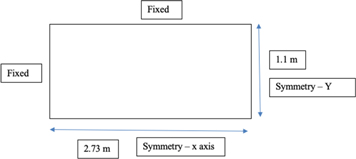
Figure 4. Boundary conditions.
Download figure:
Standard image High-resolution imageThe properties of different material of fiber reinforced composites and honeycomb core were utilized separately because the micro model and solid model was utilized and is shown in figures 5 and 6. A paper by Khan et al [12] suggests that brittle cracking model can be used to predict crack initiation in Plexiglas plate when subjected to sharp indentation loading without experiments. Hence The Failure is initiated through brittle cracking criteria for the top and bottom layer. The failure is initiated in the honeycomb core through Johnson Cook's damage criteria.
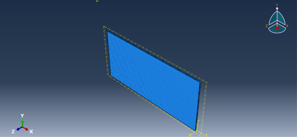
Figure 5. Final Assembly.
Download figure:
Standard image High-resolution image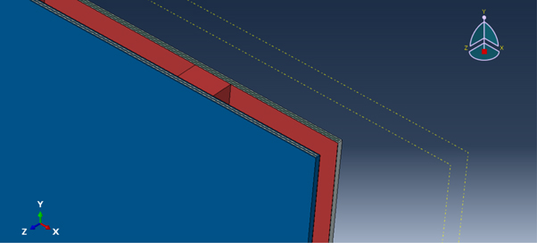
Figure 6. Final assembly exploded view.
Download figure:
Standard image High-resolution imageTable 2. (a) Mechanical properties of Steel [13]. (b) Failure properties of steel [13].
| Material | Steel |
| Density (kg m−3) | 7840 |
| Poisson's ratio | 0.29 |
| Young's modulus (Pa) | 2.05 × 10¹¹ |
| Damage criteria | Johnson cook fracture model |
| D1 | 0.04 |
| D2 | 1.03 |
| D3 | 1.39 |
| D4 | 0.002 |
| D5 | 0.46 |
| Melting temperature (C) | 1350 |
| Transition temperature (C) | 25 |
| Reference Strain rate | 1 |
The damage initiation criteria for fibre reinforced composites are based on Hashin's theory. These criteria consider four different damage initiation mechanisms: fibre tension, fibre compression, matrix tension and matrix compression.
Prior to any damage initiation and evolution the damage operator, M, is equal to the identity matrix so  Once the damage initiation and evolution has occurred for at least one mode, the damage operator becomes significant in the criteria for damage initiation of the modes. The effective stress,
  is intended to represent the stress acting over the damaged area that effectively resists the internal forces.
Table 3. Properties of Top layer [14].
| Matrix | Zirconium diboride |
| Young's modulus (Pa) | 4.89 × 10¹¹ |
| Density (kg/m3) | 6260 |
| Poisson's ratio | 0.15 |
| Reinforcement | Silicon Carbide |
| Young's modulus (Pa) | 1.37 × 10¹¹ |
| Density (kg m−3) | 4840 |
| Poisson's ratio | 0.37 |
The initiation criteria can be specialized to obtain the model proposed by Hashin and Rotem (1973) by setting  and
and  or the model proposed in Hashin (1980) by setting
An output variable is associated with each initiation criterion (fibre tension, fibre compression, matrix tension and matrix compression) to indicate whether criterion has been met. A value of 1.0 or higher indicates that the initiation criterion has been met. If you define a damage initiation model without defining an associated evolution law, the initiation criteria will affect only output. Thus, these criteria can be used to evaluate the propensity of the material to undergo damage without modeling the damage process.
Table 4. Properties of bottom layer [15, 16].
| Matrix | PEEK |
| Young's modulus (Pa) | 3.95 × 10⁹ |
| Density (kg/m3) | 1320 |
| Poisson's ratio | 0.3931 |
| Reinforcement | PBO |
| Young's modulus | 1.8 × 10¹¹ |
| Density (kg/m3) | 1540 |
| Poisson's ratio | 0.2 |
The Johnson-Cook failure model has been used to model ductile failure of materials experiencing large pressures, strain rates and temperatures. The model is constructed in a similar way to the Johnson-Cook Plasticity model where it consists of three independent terms that define the dynamic fracture strain as a function of pressure, strain rate and temperature.

The ratio of the incremental effective plastic strain and effective fracture strain for the element conditions is incremented and stored in custom results variable, DAMAGE. The material is assumed to be intact until DAMAGE = 1.0. At this point failure is initiated in the element. An instantaneous post failure response is used.
Abaqus/Explicit uses a smeared crack model to represent the discontinuous brittle behavior. It does not track individual macro cracks; instead, constitutive calculations are performed independently at each material point of the finite element model. The presence of cracks enters into these calculations by the way in which the cracks affect the stress and material stiffness associated with the material point. The term 'crack' is used to mean a direction in which cracking has been detected at the single material calculation point in question: the closest physical concept is that there exists a continuum of micro-cracks in the neighbourhood of the point, oriented as determined by the model. The anisotropy introduced by cracking is assumed to be important in the simulations for which the model is intended.
The Abaqus/Explicit cracking model assumes fixed, orthogonal cracks, with the maximum number of cracks at a material point limited by the number of direct stress components present at that material point of finite element method (a maximum of three cracks in three dimensional, plane strain, and axisymmetric problems; two cracks in plane stress and shell problems; and one crack in beam or truss problems). Internally, once cracks exist at a point, the component forms of all vector and tensor-valued quantines are rotated so that they lie in the local system defined by the crack orientation vectors (the normals to the crack faces). The model ensures that the se crack face normal vectors will be orthogonal, so that this local crack system is rectangular Cartesian. For output purposes you are offered results of stresses and strains in the global and/or local crack systems.
A simple Rankine criterion is used to detect crack initiation. This criterion states that a crack forms when the maximum principal tensile stress exceeds the tensile strength of the brittle material. Although crack detection is based purely on Mode I fracture considerations, ensuing cracked behaviour includes both Mode I (tension softening/stiffening) and Mode II (shear softening/retention) behaviour. As soon as the Rankine criterion for crack formation has been met, we assume that a first crack has formed. The crack surface is taken to be normal to the direction of the maximum tensile principal stress. Subsequent cracks may form with crack surface normals in the direction of maximum principal tensile stress that is orthogonal to the directions of any existing crack surface normals at the same point. Cracking is irrecoverable in the sense that, once a crack has occurred at a point, it remains throughout the rest of the calculation. However, crack closing and reopening may take place along the directions of the crack surface normals. The model neglects any permanent strain associated with cracking; that is, it is assumed that cracks can close completely when the stress across them becomes compressive.
An important feature of the cracking model is that, Crack initiation is based on Mode I fracture only, post cracked behaviour includes Mode II as well as Mode I. The Mode II shear behaviour is based on the common observation that the shear behaviour depends on the amount of crack opening. More specifically, the cracked shear modulus is reduced as the crack opens. A shear retention model in which the post cracked shear stiffness is defined as a function of the opening strain across the crack; the shear retention model must be defined in the cracking model, and zero shear retention should not be used.
In these models the dependence is defined by expressing the post cracking shear modulus, GC, as a fraction of the uncracked shear modulus:

where G is the shear modulus of the uncracked material and the shear retention factor,  depends on the crack opening strain,
  '
'
As different layer of the sandwich composite was modelled separately, they were joined together in assembly module in Abaqus and tied together using a tie constraint [17]. From the previous section, we know that the load is approximated as a triangular pulse and from TM 5 1300 (1990) manual [1] we found that for initial analysis the load can be assumed as a uniform load to reduce the complexity involved in the analysis. Hence the load was given as a triangular pulse which is uniformly distributed over the top surface of the sandwich composite. For this analysis swept meshing was utilized to mesh the geometry. The swept meshing technique involves two phases: Intially the software creates a mesh on one side of the region, known as source side and then the software copies the nodes of the mesh, one element layer at a time, until the final side known as the target side is reached. Abaqus/CAE copies the nodes along an edge, and this edge is called the sweep path. The sweep path can be any type of edge- a straight edge, a circular edge or a spline. If the sweep is a straight edge or a spline, the resulting mesh is called an extruded swept mesh. If the sweep path is a circular edge, the resulting mesh is called a revolved swept mesh.
In addition, the sweep path controls the default orientation of hexahedral and wedge elements that are used to model gaskets, continuum shells, cylindrical region using cylindrical elements and adhesive joints using cohesive elements.
Four—node doubly curved thin or thick shell, reduced intergration, hourglass control, finite membrane strains were used for the finite element modeling of the structure. The settings are required to obtain a result that can be used to make predictions. Excessive distorted elements will lead to errors aborting the analysis. Hence element deletion option is used which deletes based on the failure criteria. Second order accuracy and hourglass controls are used to obtain more accurate results. The total number of elements was about 110,326.
Results and discussions
According to an investigation by Tiju Thomas and Gaurav Tiwari [18], the response of honeycomb structure to quasi static and dynamic loading was dependent on design parameters of the honeycomb structure like relative density of the core, cell configuration, cell wall thickness, node length and cell size. Relative Density was one of the most influential parameters in determining the performance of the Honeycomb in static and dynamic conditions.
This analysis explores the effect of modifying the face dimension of the honeycomb core on the sandwich composite. Figures 7 and 8 show honeycombs with different cell densities where cell density of figure 7 is higher than the cell density of figure 8. Two models with same dimensions of the top and bottom layer but one having HC-coarse and the other having HC-fine as its core were considered for analysis.
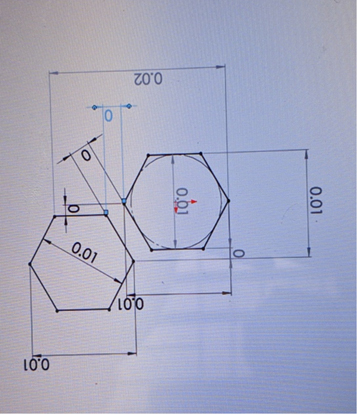
Figure 7. Dimensions of HC-fine.
Download figure:
Standard image High-resolution image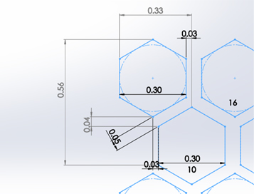
Figure 8. Dimensions of HC-coarse.
Download figure:
Standard image High-resolution imageFigure 9 shows that higher the cell density of the honeycomb core higher the amount of internal energy the sandwich composite. This shows that the core with higher cell density can absorb more energy through deformation before failure. Therefore, increasing the cell density of the honeycomb core increases the strength and toughness of the sandwich composite.

Figure 9. Effect of changing face dimension of the core on the sandwich composite.
Download figure:
Standard image High-resolution imageThe effects of changing the thickness of the top layer ceramic matrix composite were also studied. Three models whose dimensions are given in table 5 were considered for analysis.
Table 5. Models chosen to study the effects of variation of thickness of top layer on the sandwich composite.
| Description: | Model-1 | Model-2 | Model-3 |
| Top layer thickness | 3 mm | 5 mm | 10 mm |
| Core thickness | 15.5 mm | 15.5 mm | 15.5 mm |
| Bottom layer thickness | 3 mm | 3 mm | 3 mm |
Figure 10 shows that increasing the thickness of the top layer increases the amount of energy the sandwich composite can absorb before failure. This might be due to the fact that with an increase in thickness of the top layer the amount of molecules available for interaction also increases which effectively disperses the load to the fibers and the other layers of the sandwich composite. Therefore, Increasing the thickness of the top layer increases the strength and toughness of the sandwich composite.

Figure 10. Changing the thickness of ceramic matrix composite.
Download figure:
Standard image High-resolution imageThe dimensions given in table 6 was used to model the sandwich composite and figure 7 was chosen for the face dimension of the honeycomb core.
Table 6. Final thickness for the sandwich composite.
| Top layer | 5 mm |
| Honeycomb core cell height | 21.5 mm |
| Bottom layer | 5 mm |
After finalizing the dimensions, the model was subjected to various blast loads and its performance was compared with the performance of armored steel to find out which material offers better protection.
Figure 11 shows that the amount of energy absorbed by the sandwich composite is higher than the amount of energy absorbed by steel. Therefore, the energy of the shock wave after passing through the material is lower for the sandwich composite than for steel. This results in sandwich structure offering better protection than steel when exposed to an explosion of 1 kg TNT.

Figure 11. Performance of sandwich composite and steel under explosive load of 1 kg TNT.
Download figure:
Standard image High-resolution imageFigure 12 shows that the amount of energy absorbed by steel and sandwich composite is approximately equal. This might be due to the failure of the top layer exposing the core to the blast environment. Hence, the amount of material available to withstand the blast load is reduced in the case of sandwich composite whereas it is still the same for steel.
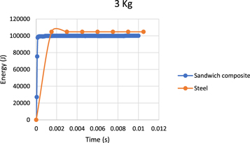
Figure 12. Performance of sandwich composite and steel under explosive load of 3 kg TNT.
Download figure:
Standard image High-resolution imageFigure 13 shows the amount of energy absorbed by steel is higher than that of sandwich composite when exposed to an explosion of 10 kg TNT. The difference in performance is because the load exerted on the Sandwich structure due to the detonation of 10 Kg TNT results in complete failure of top layer—ceramic matrix composite and bottom layer—polymer matrix composite. This results in maximum deformation of the honeycomb core. Due to the above event, the performance of sandwich composite is very less when compared to that of steel.

Figure 13. Performance of sandwich composite and steel under explosive load of 10 kg TNT.
Download figure:
Standard image High-resolution image
Discussion
The main objective of this analysis was to study the performance of the sandwich composite and compare it with the performance of armored steel to find whether the sandwich composite is a better material than steel for blast protection. To achieve the above objective various models were made varying the dimensions of the different layers of the sandwich composite and their effects on the performance of the sandwich composite were studied. Finally, the dimensions of different layers of the sandwich composite were finalized, modeled and analyzed for blast load by varying the amount of TNT.
Figure 8 shows that decreasing the honeycomb's cell size increases the energy absorption character of the honeycomb panel. A similar result was obtained in a study by Mete Onur Kaman and Murat Yavuz Solmaz [19] Where it was seen that the buckling strength of the specimens increases by the increase of core density. This might be because as the core density increases more surface is in contact with the force. Hence, the load gets distributed uniformly throughout the honeycomb structure resulting an increase in buckling strength.
Figure 12 shows the demarcating point. Till this point, the sandwich composite performs better than steel and beyond this point armored steel performs better than the sandwich composite. The trend shown by the composite material in the figures 11–13 is due to the fact that composites are brittle in nature. They absorb energy until their maximum strength is reached and breakdown or result in the formation of cracks when the load exceeds its maximum strength. The plot of energy versus time from Uddin et al [20] study is similar to figures 11–13. The initiation of internal damage is characterized by the first fluctuations in the energy versus time plot. After the initial damage, the maximum load is observed at the point where the material fails. This point marks the onset of the propagation phase and the cracks propagate through the material rapidly. Following the failure of the material due to shear, the load drops linearly to zero and the impact event ends.
The trend shown by armored steel in figures 11–13 is due to the fact that armored steel is ductile in nature and it absorbs energy through deformation. Hence, as the load increases the deformation of steel increases and hence the amount of energy absorbed increases. This similar trend is found in a study by Dariusz Szwedowicz et al [21] where the amount of energy absorbed increased with displacement and was verified experimentally.
The use of armor in a vehicle increases the weight of the vehicle by tenfold. This increase in weight not only increases fuel consumption but also limits the use of these vehicles within a geographical boundary. Steel is the currently utilized material for blast protection. Due to its low strength to weight ratio, it adds more than 2 tonnes to the weight of a vehicle. From the literature survey, all the materials proposed for blast protection do not try to solve this problem.
The studies performed until now did not consider weight as a constraint. Hence, in this study, a lightweight sandwich composite was designed. The dynamic behavior of the chosen composite was analyzed using FEM for different blast loads. Its performance was characterized by the amount of energy absorbed by the material upon impact and was compared with that of steel to find whether it's a better alternative to steel so that steel can be replaced by a light weight material which offers better protection than steel.
Conclusion
Explosive devices are improving day by day increasing the damage caused by an explosive. But the improvements made to the material used for blast protection is very less. Therefore, a new material with light weight and high strength to weight ratio is required to improve the currently available blast protection. A lightweight sandwich composite was proposed in this paper as a candidate for blast protection. It was analyzed using FEM and its performance was compared with that of steel. This investigation has led to the following conclusions.
- The top layer- Ceramic matrix composite is a very important part of the sandwich structure as it faces the impact load from the explosion. The composite performs better than steel until the strength of the top layer is reached.
- Once the top layer fails it results in excessive deformation of the honeycomb core and the failure of the bottom layer.
- Therefore, the sandwich composite with the given thickness of the top and bottom layer and the configuration of honeycomb core taken for this study will perform better than steel only under a given working condition
- Its usage reduces the weight of the material used by one-third, in numbers weight of the composite is approximately 920 Kg, whereas that of steel is approximately 2.7 Tonnes (for the given dimensions).
- Beyond the working conditions, the performance of the sandwich composite degrades and it becomes lower than that of armored steel.
Scope for future work
This investigation has proved that the proposed composite is a better performer than steel under a given working condition and reduces the weight of the material required by almost one third when compared with steel. To extend the working condition of the material
- Different shapes of honeycomb cores and different orientation of honeycomb cores can be researched
- The thickness of the top layer and the bottom layer of the sandwich composite can be varied and the performance of the sandwich composite can be studied, thus effectively extending the working condition of the sandwich composite.
- The best method to manufacture the sandwich composite should be found. Compression molding preferred for high volume production. Hand layup or vacuum bagging is preferred for low volume production
- The best adhesive that can ensure perfect contact between the composite layers and the steel honeycomb core should be found [22].
- The best cementary for the reinforcement used in the top and bottom layer can be found experimentally
- The best volume fraction of the matrix and reinforcement of the top and bottom layer can be found experimentally.
- The performance of the sandwich composite and steel can be compared experimentally.