
Abstract
Single molecule localization microscopy (SMLM) allows the imaging of cellular structures with resolutions five to ten times below the diffraction limit of optical microscopy. It was originally introduced as a two-dimensional technique based on the localization of single emitters as projection onto the x-y imaging plane. The determination of the axial position of a fluorescent emitter is only possible by additional information. Here we report a method (spatial filter SMLM (SFSMLM)) that allows to determine the axial positions of fluorescent molecules and nanoparticles on the nanometer scale by the usage of two spatial filters, which are placed in two otherwise identical emission detection channels. SFSMLM allows axial localization in a range of ca. 1.5 μm with a localization precision of 15 - 30 nm in axial direction. The technique was utilized for localizing and imaging small cellular structures - e.g. actin filaments, vesicles and mitochondria - in three dimensions.
Export citation and abstract BibTeX RIS

Original content from this work may be used under the terms of the Creative Commons Attribution 4.0 licence. Any further distribution of this work must maintain attribution to the author(s) and the title of the work, journal citation and DOI.
Introduction
Over the past hundreds of years technical development in advanced microscopy designs and manufacturing improvement gave us the opportunity to visualize cells, cell organelles and other subcellular structures with high image quality and minimal aberration. A severe restriction of the application of fluorescence microscopy is the limited resolution obscuring the detection of smaller structures. The highest achievable point-to-point resolution in glass-based optical microscopy is determined by the diffraction of excitation and emission light that cannot be surmounted by rational alternations in objective lens or aperture design. This resolution barrier is referred to as diffraction limitation, and the smallest distance that the images of two small objects could be distinguished in the imaging plane is identified as optical resolution, typically 200 - 300 nm in lateral direction and 500 nm along the optical axis, which was described already in the late 19th century [1, 2].
Recent developments in super-resolution microscopy allow to record or construct fluorescence images with resolution far better than the diffraction limited resolution of optical microscopy. In one branch of super-resolution microscopy the improvement is based on the exploitation of high localization precision of individual photo-activated and photo-switchable fluorescent labels used as markers for cellular structures and proteins. There exist many different realizations of the principle (like PALM [3], STORM [4], dSTORM [5–7], SMACM [8]) all sublimed as Single Molecule Localization Microscopy (SMLM). It is not breaking Abbe's diffraction limit but circumventing it. While it is impossible to distinguish two small fluorescent objects at one time whose distance is less than the optical resolution limit, it is possible to distinguish them in a consecutive detection mode, with only one of the two emitters fluorescing at a time. The localization precision for single molecules is typically 10 - 30 nm and hence an order of magnitude better than the diffraction limited resolution. Here, temporal resolution is sacrificed to improve the spatial resolution. When applied to many - usually 105 to 107 molecules - it allows to tempo-spatially distinguish and detect the single molecule emission patterns of all fluorescent molecules of a cell, to localize them individually and generate images of cellular structures with 20 nm to 50 nm - at best 10 nm [9] - precision.
While the lateral centroid of images of single fluorescent labels can be determined by an approximation of the central disk of the Airy pattern by a two-dimensional Gaussian function that is used as a fitting model, determination of the axial position of a fluorescent molecule or particle has its own specific problems. In axial dimension using conventional fluorescence microscopy modalities the diffraction limited optical resolution amounts to 2πλ/NA2, where λ is the average wavelength of illumination in transmitted light or the excitation wavelength band in fluorescence, and NA is the objective numerical aperture, corresponding to a depth of field of around 500 nm for wavelength in the visible spectral region. Improvements in three-dimensional (3D) localization beyond the diffraction limit in single molecule imaging are possible by using different strategies. One 3D localization strategy is based on the optical alteration of the shape of the point spread function as a function of axial depth. Examples are the astigmatism technique [10] and the double-helix point spread function (DH-PSF) technique [11]. The other strategy is based on the comparison of the intensity of single molecules collected by more than one image simultaneously, like biplane [12], multifocal plane PALM [13] and interferometric PALM [14]. Recently, approaches to extract 3D localization information from two-dimensional SMLM images by analyzing details of the experimental PSF's of individual emitters have been implemented successfully [15, 16] reaching similar results as the other established methods.
Here we introduce a new principle, which makes use of spatial filter technique to localize nanometer-sized fluorescent particles in three dimensions (Spatial Filter SMLM, SFSMLM). While the lateral position of the molecule can be determined from the centroid of its image in the x-y plane, the axial (z) position of the particles can be calculated from the comparison of single molecule emission intensities detected by two EMCCDs after passing spatial filters that were symmetrically placed in the emitting imaging path. Employing fluorescent polymer beads as reference specimens, we demonstrate 12–17 nm localization precision in lateral dimensions (x, y) and 15–31 nm localization precision in axial dimension over an axial range of 1.5 μm. We also show the realization of the principle in PALM and dSTORM measurements of cellular structures (actin filaments, endosomal vesicles, mitochondria).
Results
Principle of SFSMLM
The setup of SFSMLM is shown in figure 1(A). The spatial filters have high optical transmittance at the rim that increases towards the center. Thus the fluorescence intensities of single fluorescent molecules and nanoparticles registered by the two EMCCDs differ depending on the axial positions of the particles as a consequence of the anti-symmetric placement of the two spatial filters with respect to the focal plane. As a consequence, the light of fluorescent molecules and nanoparticles situated above or below the image plane will be differently attenuated. This fluorescence intensity difference can be utilized to determine the axial position of the emitters.
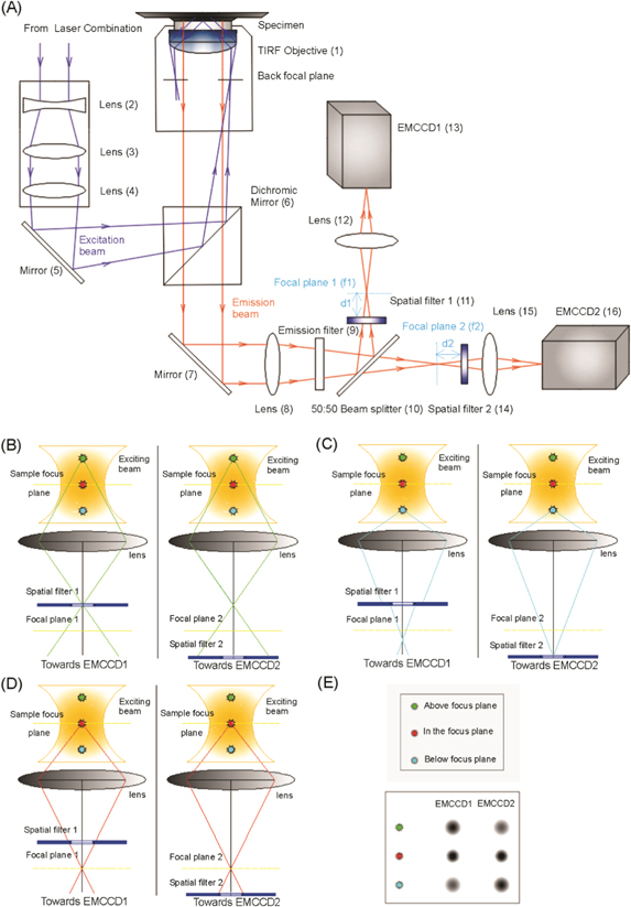
Figure 1. (A): Experimental setup of SFSMLM method. The setup of SFSMLM is composed of a conventional inverted microscope (Olympus IX71) and two orthogonal fluorescence imaging systems, which are shown in figure 1(A). Each of the fluorescence imaging system consists of one spatial filter (see below), one focus lens (for EMCCD imaging), and an electron-multiplying (EMCCD) camera. A lens (8) was placed in the emission light path that focus the detected fluorescence light from the object before the two cameras, an emission filter (9) blocks the excitation light and selects the desired emission light and a 50%:50% (intensity) beam splitter (10) is used to separate the observed fluorescence signals into two perpendicular paths. In addition, two continuously variable inverse spatial filters (see supplementary figure S6) were placed before and behind the focus of Lens 8, respectively, at same distance relative to the focal planes in the two detection pathways (figure 1(A)). The distance (d1) between Spatial filter 1 (set in front of Focal plane 1) and Focal plane 1 (f1) in one optical path, is the same as the distance (d2) between Spatial filter 2 (set behind Focal plane 2) and Focal plane 2 (f2) in the other optical path. Lens (15) and Lens (12), which collect the fluorescence light from the foci of Lens (8), have identical focal lengths. (B) - (E): Principle of SFSMLM technique. (B): Optical path of emission from a single fluorophore above focal plane; (C): Optical path of emission from a single fluorophore below focal plane; (D): Optical path of emission from a single fluorophore in focal plane; (E): Comparison of fluorescence intensity on the two cameras for the three cases (B) - (D).
Download figure:
Standard image High-resolution imageTo visualize the working principle of SFSMLM (figures 1(B) - (E)), we simplified the two optical paths in figure 1(A) to only one objective plane, one lens and one imaging plane in each direction (figures 1(B) - (E)). In each optical path spatial filters were placed at the same distance in front of or behind the focal plane, respectively. The focusing lenses after the spatial filter and the EMCCDs are not shown.
The position of single fluorescent emitters in microscopy falls into one of three cases with respect to the focal plane: above the focal plane, in the focal plane and below the focal plane. In the first case (figure 1(B)), when the z-position of the emitter is above the focal plane, the fluorescent signal in path 1 will pass almost non-attenuated through the spatial filter while the fluorescent signal from the same emitter in path 2 will be partially absorbed by the spatial filter. Therefore, the fluorescent signal of the single emitter on EMCCD1 has higher intensity than that on EMCCD2 (figure 1(E)). In the reverse situation, when the z-position of the single emitter is below the image plane (figure1(C)), the fluorescent signal of the single emitter in path 1 will be partially absorbed by the spatial filter while the fluorescent signal from the same emitter in path 2 can pass through the filter with no substantial loss. As a consequence, the fluorescence intensity of the single emitter on EMCCD1 will be weaker than that on EMCCD2 (figure 1(E)). Finally, we consider the symmetrical case (figure 1(D)), when the single fluorescent nanoparticle is in the focal plane. The attenuation of the fluorescence of the single emitter by the two spatial filters is the same in both optical paths, thus the fluorescent signals on both EMCCDs have the same intensity (figure 1(E)). This is the principle of spatial filter SMLM (SFSMLM), which allows - by comparison of the relative fluorescent intensities of the same single emitter on the two EMCCDs - to determine the axial position of single fluorescent emitters.
Precision of localization
To quantify axial localization range and localization precision of the spatial filter technique fluorescent polymer beads (diameter: 170 nm) were imaged and analyzed over a number of defined axial bead positions. First, it was necessary to determine suitable positions of the spatial filters. We did test different positions of the spatial filters, i.e., ±0.5 cm, ±1.0 cm, ±1.5 cm, ±2.0 cm from the focal plane. In the case of ±0.5 cm the fluorescent beads can be localized in the range via the intensity ratio (ISF+/ISF-) curve (see below). The one-to-one correspondent range amounts to more than 1.5 μm, which was the largest found. Therefore, we choose the spatial filter positions ±0.5 cm from the focal plane for data analysis. More details can be found in Supplementary information (figure S2).
The microscope stage was moved in steps of 100 nm along the optical axis. The fluorescence images of the beads at each z-position were measured up to 50 times. The excitation intensity and the image acquisition parameters were adjusted such that the bead signal was comparable with that of an individual fluorophore in real biological imaging. Two-dimensional Gaussian fitting was utilized to determine the x- and y-positions and most importantly the fluorescence intensity of the fluorescent bead as measured by the amplitude of the fitted Gaussian function at each z-position for both spatial filter positions (ISF+ and ISF-). Figure 2(A) shows the fluorescence intensities obtained from the fitted Gaussian functions as a function of the axial bead position for the spatial filter distance of +0.5 cm (in path 1) and −0.5 cm (in path 2), respectively. The ratio of the fluorescence intensities (ISF+/ISF-) - the suggested readout parameter for the axial position in the SFSMLM method - is depicted in figure 2(B). No influence of the bead position within the field of view (at least 20 μm) was found (see supplementary figure S7). To reduce drift effects over the course of the measurement the image acquisition time was minimized. The measured symmetrical amplitude versus axial position curves for the two consecutive z-scans that intersect each other exactly in the focal plane (x = 0) in figure 2(A) indicate that no significant drift variations over the whole recording process have occurred.
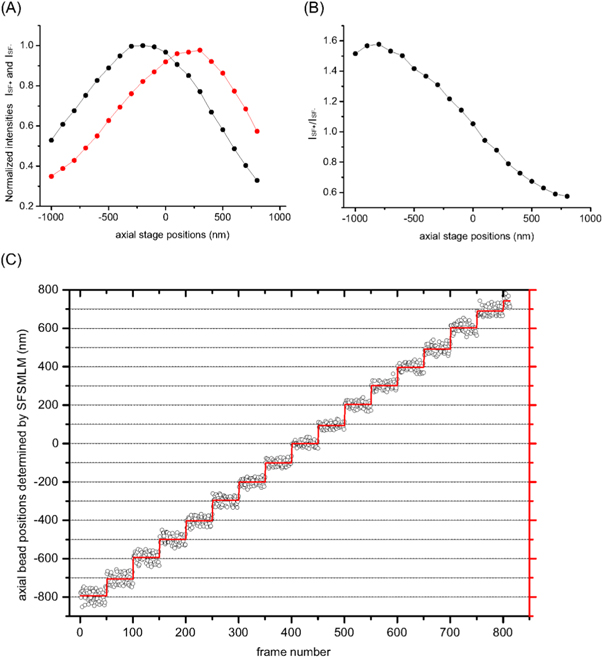
Figure 2. Three-dimensional imaging of fluorescent bead with SFSMLM: (A) Fluorescence intensities ISF+ and ISF- of a fluorescent bead as a function of the axial position of the piezoelectric nano-positioning stage determined with spatial filters placed at + 0.5 cm (in path 1) and - 0.5 cm (in path 2) relative to focal plane, respectively. (B) Ratio ISF+/ISF- as a function of axial stage position. (C) Comparison of measured axial positions of fluorescent polymer beads (diameter: 170 nm; black hollow circles) at different axial displacement of the piezoelectric nano-positioning stage (black dotted line) and the average values of the experimentally determined z-positions (red line).
Download figure:
Standard image High-resolution imageFigure 2(C) shows the measurements of the axial position of fluorescent polymer beads (diameter: 170 nm) compared with the displacement of the piezoelectric nano-positioning stage. A satisfactory agreement between the stage position and the experimentally detected bead localization is apparent in a z-range from - 800 nm to 700 nm.
The localization accuracies in axial and lateral directions were determined as standard deviation σ from 50 images taken at each z-position. The lateral localization precision was found to be between 12 and 16 nm with a systematic increase at positive axial stage positions, while the axial localization precision was slightly larger (between 15 and 31 nm) and with a systematic trend (supplementary material figures S3(D), (E))
In SFSMLM it is clear that the introduction of two spatial filters in two perpendicular optical paths altered the distribution of optical field which led to the shift of focus ∼400 nm front or below the focal plane. The effect is similar to the principle in biplane method, the only difference is that in biplane not spatial filters but at least one or more receiver like EMCCD was artificially moved away from focus to record different defocus imaging planes. Thus it is reasonable to compare the two methods. In biplane we utilized 170 nm fluorescent beads and used the same image splitter, separated the focal planes of the two channels by ∼400 nm, used the full-width half-maximum width (FWHM) information of the spots, and measured a calibration curve with the ratio of FWHMs of the same bead for each channel as a function of z (supplementary figure S3(A)), and then determined the lateral and axial precision to 12–17 nm and 15–35 nm (standard deviation), individually. (supplementary figures S3(C), (D), (E), table S3), and retrieved absolute axial coordinates around a range of 1 μm (supplementary figures S3(B)). In contrast with biplane, with SFPALM we were able to determine the absolute axial coordinates range 1.5-fold larger than classical biplane imaging.
Imaging actin filament network in HeLa cells
To test the robustness and performance of 3D SFSMLM super-resolution microscopy, we first applied it to directSTORM (dSTORM) imaging of actin filaments [6] in HeLa cells stained with fluorescently labelled phalloidin (figure 3). Actin is a globular 42 kDa protein that is abundant in almost all eukaryotic cells. It is essential for many cellular functions, ranging from cell motility and the maintenance of cell shape and polarity to the regulation of transcription [17]. Actin has the ability to polymerize from monomers (single protein, G-actin) to short and long filaments (F-actin) and filament bundles [18, 19]. These filaments form a fibrous network together with different filaments and tubules formed by other proteins within cells called the 'cytoskeleton', which provides cells with mechanical integrity and shape.

Figure 3. 3D Super-resolution images of actin filaments in fixed HeLa cell. (A) TIRF image (B) two-dimensional super-resolution dSTORM image (projection onto x,y-plane). White box indicates the zoomed region depicted in (C) and (D). (C) three-dimensional super-resolution dSTORM image obtained with SFSMLM of region indicated in (B). Color scale decodes the z-position. (D) Same image as in (C) shown as 2D projection. A more detailed analysis is depicted (see supplementary figure S5). The mean values of the z-heights of the localizations in the chosen filament regions 1 -7 (1 - 3 regions in actin filament 1, 4 - 5 regions in actin filament 2 and 6 - 7 regions in actin filaments 3) specified in (D) are 126 nm, 122 nm, 121 nm, 27 nm, 41 nm, 19 nm, and 51 nm, respectively. (scale bar: 5 μm).
Download figure:
Standard image High-resolution imageFigure 3 depicts a typical dSTORM image of the actin filament network of a mammalian cell recorded with SFSMLM setup. The image, obtained with the 3D super-resolution reconstruction/visualization software ViSP [20], shows a highly interconnected spatial network of actin filaments that differ in their axial positions. For instance, the axial position of filament 1 is about 50 nm higher, compared to filaments 2 and 3 in figure 3(C), i.e., the three actin filaments show apparent 'crossings' only in the 2D projection onto x,y-plane (figure 3(B)) but in fact, filaments 2 and 3 proceed about 50 nm below actin filament 1 and no interaction of the three filaments exists (figure 3(E) and supplementary figure S5).
Imaging endosomal vesicles in HeLa cells
We also applied SFSMLM to visualize the sizes and distributions of intracellular vesicles in HeLa cells (figure 4). Rab7 is a small GTPase, a key regulator for endo-lysosomal trafficking in mammalian cells and serves as a marker for vesicular structures of the late endosome [21]. Three-dimensional contours and positions of vesicles could be visualized with SFSMLM microscopy (figures 4(A) - (D)). The sizes of 16 vesicles were determined by the FWHM of Gaussian functions fitted to the projections of the localizations in x-, y-, and z-direction, while the vesicle mean positions were obtained as the center of the three Gaussian functions (table S4 in supplementary information). The projections and fits for two vesicles are given in figure 4(D). The vesicle z-positions span 270 nm. The larger uncertainty of determined z- compared to x- and y-positions is reflected in an estimated apparent asymmetry of the vesicle diameter (dx = 69 nm; dy = 81 nm; dz = 156 nm) in z-direction. For vesicles 1 and 12 the three-dimensional visualization capabilities of SFSMLM allowed to distinguish pairs of vesicles both having very similar x- and y-positions but being separated by ca. 200 nm in z-direction.

Figure 4. Super-resolution images of endosomal vesicles. TIRF (A) and SMLM images (B) of Rab7-positive vesicles in fixed HeLa cells. The white box in (B) is depicted in larger magnification in (C), where 16 vesicles are numbered. Their x-, y-, and z-positions as well as their size (FWHM in x-, y-, and z-direction) have been determined by Gaussian fitting (see table S4 in Supplementary material). The single molecule coordinates of vesicles 1 and 12 in figure (C) are depicted in (D) together with fitted Gaussian functions (red). Vesicle 12 is actually composed of two vesicles separated by 150–200 nm in x-, y-, and z-direction. The z-positions of all 16 vesicles span a range of ca. 270 nm.
Download figure:
Standard image High-resolution imageImaging mitochondrial network in HeLa cells
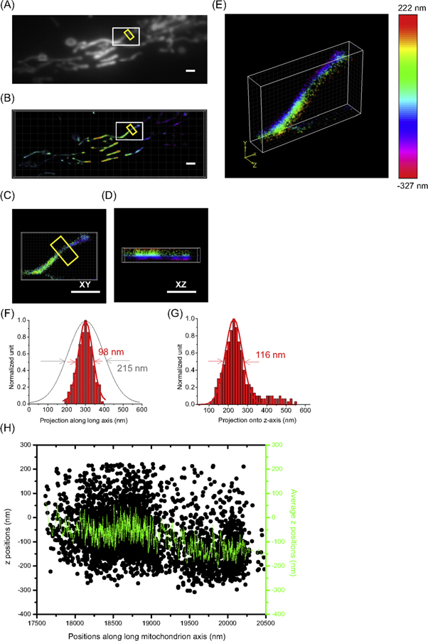
Mitochondria - the powerhouse of eukaryotic cells - are rod-like, double bilayer cell organelles with diameters of 100 nm - 200 nm and lengths of 750 nm up to 10 μm [22]. Super-resolution fluorescence microscopy is particularly well suited to visualize the complex structure of mitochondria (figure 5). Impressive SMLM images and single molecule tracking have been achieved to image christae, inner-and outer mitochondrial membrane, mitochondrial DNA, intermembrane space and mitochondrial matrix [3, 23, 24]. Photoconvertible fluorescent proteins like Dendra2 [25, 26] are an attractive alternative to blinking fluorescent proteins (like Dronpa or EYFP) [8, 27, 28]. Here, we visualized mitochondria with sub-diffraction resolution using Dendra2 connected with a target sequence for the mitochondrial matrix (mito-Dendra2) [29]. PALM images (figures 5(B) - (E)) demonstrate the ability to image the mitochondrial matrix with sub-diffraction resolution much better than TIRF imaging (figure 5(A); see also the different widths of the mitochondrial segment in x-y plane (figure 5(F))). The three-dimensional structure of the mitochondria and their extension in z-direction could be clearly visualized with 3D SFSMLM microscopy (figures 5(D), (E) and (G), (H)). The mitochondria in the middle of figure 5(B) are ca. 275 nm higher compared to those at left and right rim of the image. The mitochondrion marked by the white box in figures 5(A), (B) shows a downward kink towards lower z-positions (step size ca. 100 nm) in the middle of its length (figure 5(H)). The width of the mitochondrion in x-z plane (116 nm) is slightly larger compared to the value in x-y plane (98 nm), which can be explained by the lower precision of the determined z-position compared to x- and y-positions.
Figure 5. Super-resolution images of mitochondria network. TIRF (A) and PALM images (B) of mitochondria in fixed HeLa cells are depicted. The single mitochondrion in the white rectangle in (B) is shown as three-dimensional SFSMLM image (E) and projections in x-y (C) and x-z plane (D). The fluorescence intensity and localizations of mitochondrion in the yellow box in Figures (A) and (B), respectively, were projected on the long axis of the yellow box. The mitochondrion width in x-y plane was determined as 215 nm (TIRF) and 98 nm (PALM), respectively (F). The fluorescence localizations of mitochondrion in Figures (B) were projected on the z axis of the yellow box in x-z plane. The mitochondrion width in x-z plane was determined as 116 nm (PALM) (G). The x-z projection of all the localizations is plotted as black points on the long axis of the mitochondrion in x-direction (H). The rolling mean average (10 points) of the z-height of the localizations from adjacent averaging along the x axis is presented as green color solid line in figure (H). Between 19 200 nm and 19 400 nm a ca. 100 nm downward kink is clearly visible (scale bar: 1 μm).
Download figure:
Standard image High-resolution image
Discussion
We have presented here the principle and the application of a new method (SFSMLM) to measure three-dimensional super-resolution images. We demonstrated that the axial positions of fluorescent beads could be determined with a precision of 10–20 nm in x- and y- and 10–30 nm in z-direction by the usage of two spatial filters in the beam path of a two-camera super-resolution fluorescence microscope, which were placed before and behind the focal plane (figure 1(A)) the two otherwise symmetrical optical paths. The usable z-range of SFSMLM amounts to approximately 1 μm. SFSMLM has also been utilized for the super-resolution imaging of small cellular structures, like actin filaments, endosomal vesicles and mitochondria in three dimensions. The influence of refractive index mismatch was considered (see supplementary information and figure S4).
In contrast to three-dimensional localization methods with engineered PSF (e.g. cylindrical lens [10] or double helix [28]) in SFSMLM the individual single-molecule images used to reconstruct a super-resolution image do not need to be distorted. In addition, it is clear that in SFSMLM the main information is collected from the near-focus region, while in biplane [12] and Multifocal Plane PALM [13] it is a slightly defocusing imaging process. In the end, for 3D imaging of samples up to around half of the wavelength in thickness, interference method [14] offer incomparable localization precision, however for the reason that the interference pattern repeats itself every one-half of the wavelength of light, the working z distance is only about 300 nm. The working distance of SFSMLM is found to be 1.5 μm and therefore comparable to both biplane or cylindrical lens method.
A key issue of the SFSMLM technique is how to determine the best suited symmetrical distance between the filter and the focal plane. The intensity of fluorescent beads and fluorescent molecules decreases when the spatial filter is further away from the focal plane, which is caused by the stronger absorption of the spatial filter more near to the rim. When the spatial filter is closer to the focal plane, the slope of the one-to-one correspondent fitting curve increases (higher dynamic range) delivering better contrast and higher axial resolution. However, for the limitation of the size of the filters and other optical and mechanical components, the minimal distance between the filter and the focal plane cannot be chosen infinitely small. For the localization precision measurement with fluorescent beads and biological SFSMLM experiments the distance between the filter and the focal plane was set to 0.5 cm. In Supplementary information (figure S1 is available online at stacks.iop.org/MAF/8/025008/mmedia) further details are given. The localization precision is worse for negative axial positions due to a weak axial asymmetry of the PSF. A fluorescent particle shows intensity rings in positive axial positions but a smooth intensity distribution in negative axial positions resulting in larger localization precision for the latter.
The last aspect is the choice of proper spatial filters for SFSMLM. It is obvious, that the emission light distributions from fluorophores at different z-heights have different size and widths when impinging on the surface of spatial filters, thus it requires the spatial filter to be sensitive to this alteration. Our first attempt was to use pinholes as spatial filters. However, due to the small size of the pinholes it was difficult to record a 3D super-resolution image with a reasonable field of view. The second configuration tested were continuously variable inverse apodizing filters. With these filters the principle worked and a decent one-to-one correspondent ratio ISF+/ISF- versus z-position curve was achieved, which could be utilized to localize single fluorophores within an axial range of around 1 μm. The disadvantage of SFSMLM consists in the fact, that the spatial filter will absorb part of the useful fluorescence signal, which will lower localization precision. In the future more sophisticated spatial filters can be designed and tested that will allow SFSMLM measurements with less attenuation of the fluorescence signal and more precise z-localization in an extended z-range.
Online methods
Microscope construction for SFSMLM
The microscopy setup is based on an Olympus IX-71 inverted microscope body. A schematic drawing of the microscopy setup is shown in figure 1. The samples were mounted on a nano-positioning system (Physik Instrumente (PI) GmbH & Co., Karlsruhe, Germany) for axial scanning. Samples were illuminated with the 488 nm line of an Ar+-ion laser (Innova 70C, Coherent, Mountain View, CA, USA) for excitation of fluorescent beads (∼0.1 mW at back focal plane of objective) and phalloidin-Atto488 (∼10 mW at back focal plane of objective), a 561 nm diode laser (Sapphire 561-200 CDRH-CP; Coherent) for excitation of mito-Dendra2 (∼20 mW at back focal plane of objective), and a 642 nm diode laser (LBX-642-130 CIR-PP; Oxxius, Lannion, France) for excitation of GFP-booster-Alexa647 (∼20 mW at back focal plane of objective). In addition, we utilized a 405 nm diode laser (Cube 405 - 100C; Coherent) for photoconversion of mito-Dendra2 (∼0.1 mW at back focal plane of objective), the latter controlled via a digital/TTL signal. Excitation intensity and illumination time were adjusted via an acousto-optic tunable filter (AOTF; AA OPTO-ELECTRONIC, Orsay, France). The laser light from the laser combination box was guided to the back focal plane of the microscope via broadband dielectric mirrors (5) (450 - 700 nm) (Thorlabs, Dachau, Germany). Two achromatic lenses (2) (3) with different focal lengths (20 mm and 200 mm) were incorporated to expand the laser beam. The illuminated field aperture is then projected into the microscopy specimen by a 500 mm lens (4) and a 60×/1.49 TIRF objective (1) (Olympus APON 60×/1.49, Olympus) resulting in a circular illumination field of around 130 μm diameter (FWHM) in wide-field mode. The excitation light is reflected into the specimen by a multiband dichroic mirror (F73-866, BSR405/488/561/633, AHF Analysentechnik, Tübingen, Germany).
Emitted fluorescent light was collected through the objective (1), the multiband dichroic beamsplitter (6), and 1× tube lens (8) and was then guided to the left side port of the IX-71 microscopy body. Light was filtered by suitable dichroic (BS R405/488/561/635 (F73-866; Analysentechnik)) and emission filters (446/523/600/677 (F72-866; Analysentechnik)).
A 50:50 beam splitter (BS013; Thorlabs) was utilized to separate the fluorescent light into two perpendicular optical paths. The intermediate focus of the fluorescent light was then imaged via achromatic lens (8) (AC254-035-A-ML, f1 = 35 mm, Thorlabs) and lens (12) (AC254-050-A-ML, f2 = 50 mm, Thorlabs) in one optical path, and lens (15) (AC254-050-A-ML, f2 = 50 mm, Thorlabs) in the other perpendicular optical path, and finally was collected on the cooled (−75 °C) AndorTM iXon EMCCD cameras (Andor Technology, Belfast, Northern Ireland, United Kingdom; 512 × 512 pixels per image) which were placed on a moveable nano-positioning piezoelectric stage (M-404.4PD, Physik Instrumente (PI)). The position of the back focus of lens (8) coincides with the position of the anterior focus of lens (12) and lens (15), and the position of EMCCD is set to two times the focal length of lens (12) and lens (15), where a constant post-objective zoom of 3.56× magnification was achieved by the combination of lenses (8,12), and lenses (8,15) in two optical paths. Together with a 60× objective the final pixel size of the images is kept constant at 75 nm/pixel during the whole experiment process. Two apodizing spatial filters (Edmund Optics) were placed in equal distances in front of and behind the focal plane of lens (8) in two optical paths, respectively (figure 1(A)). The procedure to accurately determine the positions of both spatial filters is presented (see supplementary figures S1, S2). Fluorescent polymer beads (diameter: 170 nm; P-7220, Molecular Probes, Thermo Fisher Scientific, Waltham, MA, USA) were used to demonstrate the SFSMLM principle and to determine the localization precision in x, y and z-dimension.
For biplane method the emitted fluorescence of beads was imaged with an Andor iXon EMCCD camera, which was placed on a moveable stage (M-404.4PD, Physik Instrumente (PI) GmbH & Co., Karlsruhe, Germany). In combination with an achromatic lens (AC254-050-A-ML, Thorlabs, Dachau, Germany), the information in different planes near the focal plane of specimens could be recorded by placing the EMCCD camera at specific, calibrated distances from the focal plane of the tube lens.
Protein constructs
Mito-Dendra2 was constructed to obtain a genetically encoded staining of mitochondria with a photoconvertible fluorescent protein. A plasmid (pMC-MTS-EYFP) containing the gene of YFP (EYFP) fused downstream to the mitochondrial target sequence (MTS) originating from cytochrome C oxidase subunit VIII [30] was a kind gift by Dr M.O. Christensen (Heinrich Heine University Düsseldorf, Germany). The plasmid was digested with the restriction enzymes AgeI and SaII allowing the removal of the gene of EYFP and the insertion of the gene of Dendra2 (Evrogen, Moscow, Russia) downstream of the MTS.
Cell culture
HeLa cells were grown on 9 cm sterile Petri-dishes containing 8 ml minimum essential medium (MEM) supplemented with 10% (v/v) fetal calf serum (FCS), 1% (v/v) streptomycin/penicillin and 1% (v/v) essential amino acids (Life Technologies, Darmstadt, Germany). The generation time of the cell lines was approximately 24 h. At a density of approximately 90% confluence, cells were transferred onto new Petri-dishes washed with 10 ml phosphate buffered saline (PBS; 137 mM NaCl, 2.7 mM KCl, 10 mM Na2HPO4 * H2O, 1.8 mM KH2PO4 * H2O) and incubated in 0.8 ml trypsin/EDTA (0.05%/0.02%; GIBCO, Thermo Fisher Scientific) for 5 min at 37 °C. Trypsin detaches the cells by hydrolytic cleavage of adhesion proteins. The enzymatic reaction was stopped with 10 ml growth medium. Detached cells were transferred into 15 ml Falcon tubes and collected by centrifugation (5 min, 200 g). The supernatant was aspirated and the cell pellet was suspended in 10 ml medium. The cell number was determined in a 'Neubauer counting chamber' and approximately 8 × 10⁵ cells were plated onto a new petri dish. The medium was changed every two to three days. Cells were incubated at 37 °C and 5% CO2.
Calcium-phosphate transfection
Transient transfection of HeLa cells was performed in 5 cm Petri-dishes using Calcium-Phosphate precipitation. Approximately 24 h before transfection, 2 × 10⁵ cells were plated onto a Petri-dish containing 5 ml DH10 medium (GIBCO, Thermo Fisher Scientific). The desired DNA concentration (10 μg of mito-Dendra2/5 μg of Rab7-GFP) was mixed with H2O to a final volume of 124 μl. 41 μl 1 M CaCl2 and 165 μl 2× BBS (50 mM BES, 280 mM NaCl, 1.5 mM Na2HPO4, pH 6.95) was added. After incubation at RT for 20 min, the solution was added to the cells and mixed carefully. Cells were incubated for 20–22 h at 35 °C and 5% CO2.
After incubation for 20 - 22 h the transfected cells in 5 cm Petri-dishes were washed once with 3 ml PBS and once with 3 ml PBS/EDTA to remove the precipitate. After that 400 μl Trypsin/EDTA was added to the cells and incubated for approximately 5 min on a 37 °C heating block. The cells were suspended in 4.6 ml DH10 followed by centrifugation (5 min, 200 g). The pellet was suspended in 2 ml medium.
Afterwards, approximately 2–3 × 10⁴ cells were transferred to 8-well μ-Slides. To provide good cell adhesion the 8-wells were coated with 150 μl poly-L Lysine (PLL, 0.1 mg ml−1) for 30 min at RT before cells were plated. After incubation with PLL the wells were rinsed two to three times with sterile filtered PBS to reduce background fluorescence. Then 100 to 200 μl of the cell suspension was added to each well, and the volume in each well was adjusted to a total of 200 μl. Then cells were incubated for 24 h at 37 °C and 5% CO2 before experimental use.
Staining of actin filaments for super-resolution imaging
All incubation steps were performed at room temperature (RT). To reduce background fluorescence all solutions were sterile filtered. For staining of actin in fixed cells, cells were washed four times (5 min each) with PBS before fixation, then fixed with 4% paraformaldehyde (PFA) aqueous solution for 15 min, followed by washing six times with PBS (5 min each). Afterwards, cells were permeabilized with 200 μl 0.5% Triton X-100 (in PBS) for 10 min, washed two times with PBS (5 min each), and blocked with 200 μl 5%(v/v) Normal Goat Serum (NGS) for 30 min. Subsequently, cells were incubated with 200 μl Phalloidin buffer (10–100 nM phalloidin labeled with the fluorophore ATTO488 (Sigma-Aldrich, Munich, Germany) in 0.22 μm filtered PBS) for 60 min. Before transfer to the microscope, cells were washed three times with PBS + 0.1% Tween20 (10 min each) for experimental use.
Immunostaining of Rab7-EGFP construct for super-resolution imaging of vesicles
HeLa cells were first transfected with DNA encoding Rab7-GFP (Addgene; plasmid #1260529) using Calcium-Phosphate precipitation. After two days transfected cells were washed two times with phosphate-buffered saline (PBS) and then incubated at 37 °C with 4% PFA aqueous solution for 10 min. After that, cells were washed three times with PBS containing 0.1% Tween20 (PBST). Then 0.5% Trion X-100 in PBS was added and cells were incubated for 5 min at room temperature. After that cells were washed two times with PBS and then incubated with the blocking buffer (4% BSA in 0.1% PBST) for 10 min. After blocking the cells were incubated with adequate concentrations of a fluorescent nanobody labeling GFP based on an Alpaca antibody (GFP-Booster_Alexa647; ChromoTek, Planegg-Martinsried, Germany) for 60 min. The nanobody solution was prepared following the published protocol [31]. The cells were then washed three times with PBS before experimental use.
PALM
By applying 0.1 mW of 405 nm light (∼0.2 mW at back focal plane of objective), mito-Dendra2 fluorophores showed irreversible photoconversion to the orange emitting state in living HeLa cells. Typically, 500 photons were detected from single mito-Dendra2 molecule per frame (excitation intensity: ∼20 mW 561 nm at back focal plane of objective) and used for position determination. PALM image shown in figure 5(B) was reconstructed from 4000 images (pixel size: 75 nm) at frame rates of around 20 Hz corresponding to acquisition times of a 3 min 20 s for a total image. SNSMIL [27] software was utilized to reconstruct PALM image of mitochondrial network with the value 3.0 for the parameter 'quality threshold' and 'Symmetrical 2D Gaussian non-integral model' for the parameter 'fitting model'.
dSTORM
For dSTORM imaging of phalloidin-Atto488 stained actin filaments, a line of an Ar+-ion laser was used for excitation (power of 488 nm laser: ∼10 mW at back focal plane of objective, exposure time: 50 ms, pixel size: 75 nm). While for dSTORM imaging of GFP-booster-Alexa647 stained vesicles, a 642 nm diode laser was utilized (power of 642 nm laser: ∼20 mW at back focal plane of objective, exposure time: 50 ms, pixel size: 75 nm). Series of the same 4000 TIRF images were recorded in each case and subsequently analyzed for calculation of the super-resolution images. SNSMIL [29] software was utilized to reconstruct PALM image of actin filaments and vesicles with the same value 2.7 for the parameter 'quality threshold' and 'Symmetrical 2D Gaussian non-integral model' for the parameter 'fitting model'.
Acknowledgments
Xiaoming Fan acknowledges research fellowship for PhD study from Deutscher Akademischer Austausch Dienst (DAAD). We thank Mr Joachim Schmitz for the preparation of cell lines. We thank Mr David Hildebrand, Miss Yi Zheng and Miss Bojing Ma from DAAD for their constant support of our work.
Author contributions
X F had original idea of SFSMLM X F, J H, T G and G B designed experimental setup and experiments. X F performed all experiments, J H and M C contributed essentially to camera alignment and nanobody staining experiments and T G helped with data analysis. A K produced mito-Dendra2 construct. All authors discussed results and wrote ms.
Additional information
The authors declare no competing financial interests.