

Abstract
Two transformation-optics inspired flat lenses are used to build up an optical system capable of transposing an area surrounding the object focal point in a magnified area surrounding the image focal point. The object and image focal points of the system are placed in the free space and in a dilated space, respectively, having sub-unitary relative permittivity and permeability. The anisotropic and inhomogeneous media constituting the lenses enable the processing of the high spatial frequencies without converting them in evanescent waves. Numerical simulations show the capability of the proposed device for performing magnified discernible images of the sub-wavelength details.
Export citation and abstract BibTeX RIS
1. Introduction
Projective imaging systems based on lenses are the best option for high-speed optical microscopy. The image of the object is obtained by a single passing of the light through the device without involving any scanning techniques of the object. This characteristic of projective systems makes them suitable for dynamic imaging [1]. The resolution of these optical devices is limited due to the fact that sub-wavelength information from an object is carried by high spatial frequencies. Such waves having high transverse wave numbers become evanescent inside of a conventional optical lens. Consequently, their intensity decays exponentially and the sub-wavelength details of the object are not present in the reconstructed image [2]. Beginning with the seminal concept of the perfect lens [3], a number of unconventional lenses, providing sub-wavelength resolution were studied both theoretically and experimentally [4–8]. Within the last two decades, the fields of plasmonics and metamaterials have provided solutions for unconventional lens designs able to process the waves carrying the sub-wavelength details of the objects [9–11]. This has provided tremendous opportunities for designing optical imaging devices with unprecedented resolution [12–15].
The transformation-optics approach opened a path for designing anisotropic and inhomogeneous media, capable of manipulating not only the wave paths but also the wave vectors [16–19]. The change of an initial optical ray path is very intuitive when a coordinate's transformation is applied to the initial space. The transformation of the initial space also leads to a specific manipulation of the wave vector. The changes of the wave vectors are well described in the theoretical context of the transformation-optics theory. Control upon the wave vectors is required when designing focusing or defocusing devices. Recently, a general method was proposed for designing both converging and diverging flat lenses made of media that perform specific coordinate transformations [20]. The permittivity and permeability tensors of the transformation media constituting these unconventional lenses are retrieved from the transformation functions which alter the coordinates of the original space. A lens of this type provides a perfect convergence for a light beam propagating parallel to the optical axis of the lens [20]. In this theoretical study, we propose an optical imaging system, based on two converging transformation-optics inspired flat lenses, which provides magnified images for sub-wavelength features.
2. Optical system description
Considering the z-axis as the optical axis of the proposed system, the transformation media of the lenses used to build up the device are generated by functions which transform only the z coordinate of the original space, z → z/h(x, y) through the transformation function h(x, y), while the x and y coordinates remain unaltered. Giloan et al [20] described in detail the steps leading to the retrieval of the transformation function which generates the medium of a converging lens embedded in the free space, i.e. relative permittivity and permeability are equal to unity. Following the same steps, one can easily prove that for a converging lens of thickness d and focal length φ embedded in an isotropic and homogeneous medium having the same relative permittivity and permeability, ε = μ = m, the lens medium is generated by the following transformation function

where δ = 1 + φ/d and γ = 1/d. The parameter δ is a scaling factor, which sets the value of h function to m for the points placed on the optical axis of the lens (x = y = 0). In this way, the points from the optical axis of the lens and the points of the surrounding medium of the lens will have the same metric. Consequently, an optical ray propagating along the optical axis of the lens will encounter no reflection at the interface between lens and surrounding medium [21]. When m = 1, we are in the case of a lens embedded in the free space ε = μ = 1. The cases when parameter m is supra-unitary (m > 1) or sub-unitary (m < 1) can be viewed as an additional transformation of the space like a compression or dilation, respectively. Regardless of the value of parameter m, the optical parameters of the lens generated by transformation function described by equation (1) are positive inside the area delimited by the circle given by equation

where ρ = d/φ is the thickness to focal length ratio of the lens.
The concept of the optical system presented in this paper is schematically represented in figure 1. The (y−z)-plane view of two identical converging flat lenses joined at the plane z = 0 and embedded in the free space (green rectangles) is depicted in figure 1(a). The lenses have a thickness to focal length ratio equal to four (ρ = 4). Since the proposed device is confined to positive optical parameters of the constituent lenses the depicted area is limited on the y-axis by the singularity point  derived from equation (2). The left and right lenses, depicted by red and blue rectangles, correspond to negative and positive values of z-coordinate and will be named the object and image lenses, respectively. The geometrical parameters, like focal length φ, thickness d, focal point F, and outside plane P, are denoted for the object and image lenses with the subscripts o and i, respectively. The curves of constant transformed z coordinate are depicted by red and blue lines inside the area of the object and image lenses, respectively.

Figure 1. (a) (y−z)-plane view of two identical transformation-optics inspired flat lenses joined at the plane z = 0 and embedded in free space (green). The thickness, focal length and focal point of the object lens (red) are denoted by do, φo and Fo respectively, while for the image lens (blue) are denoted by di, φi and Fi, respectively. The front plane of the object lens and the back plane of the image lens are denoted by Po and Pi, respectively. The device span on the y-axis is bounded by the singularity points ±ys. (b) (y−z)-plane view of the first variety of the proposed optical device. The image lens (light blue) is adjacent to the image dilated space (light green) which extends until the right end of the proposed device. (c) (y−z)-plane view of the second variety of the proposed optical device. The image lens (light blue) is adjacent to the image dilated space (light green) which is bounded by the image focal plane of the proposed device. An absorption layer (yellow) of thickness a, is inserted between lenses.
Download figure:
Standard image High-resolution imageTwo varieties of the proposed optical system are depicted in figures 1(b) and (c). The setup of the studied optical device is obtained from the setup depicted in figure 1(a) by applying two changes. The first change is that the image lens and its adjacent free space are dilated by a factor of 4. Hence, the transformation function which gives the permittivity and permeability of the image lens (light blue) is obtained from equation (1) where parameter m has the value 1/4 (m = 1/4) and the area adjacent to the object lens (light green) has the permittivity and permeability equal to 1/4 (ε = μ = 1/4). The second change consists of an insertion of an absorbing layer (yellow) of thickness a, between the object and image lenses. The first variety of the studied optical system is depicted in figure 1(b) and it has the dilated area adjacent to the image lens extended over the image focal plane until the right end of the simulation area. The second variety of the studied optical system is depicted in figure 1(c) and it has the dilated area adjacent to the image lens extended only until the image focal plane. The curves of constant transformed z coordinate are depicted as rarefied inside the area of the image lens in order to suggest the dilation transformation applied to this lens. Although, the image lens was transformed, the area of positive optical parameters (permittivity and permeability) remain the same for both lenses and is bounded by the singularity circle having the radius equal to  (see equation (2)). The numerical simulations presented in section 3 have been performed in two cases: (1) the radius of the component lenses (lR) is extended to the singularity points lR = ys; (2) the radius of the component lenses lR is reduced by 10% from the singularity radius (lR = 0.9ys). The boundaries of the devices with reduced radius lenses are depicted in figures 1(b) and (c) by brown dashed lines.
Any optical ray emerging from the focal point of the object lens (Fo) and incident to the outside plane of the object lens (Po) will continue to propagate through the device parallel to its optical axis (z-axis) and when arriving at the outside plane of the image lens (Pi) will be deflected right through the focal point of the image lens (Fi). In other words, for the studied optical system the image focal point (Fi) is the perfect image of the object focal point (Fo), but in a geometrically dilated space. Due to this property, the proposed optical device will transpose the object points comprised in a small vicinity around the object focal point (Fo) in image points comprised in a magnified vicinity around the image focal point (Fi).
The path of an optical ray leaving the object focal point Fo under an angle α with the z-axis and arriving into the image focal point Fi under the same angle α with the z-axis, is depicted in figure 1(b) by straight orange lines. The electromagnetic wave following this path, from Fo to Fi, will be affected by reflection/transmission at the input Po and output Pi interfaces of the device. In the study of this optical device, of particular interest, are the transmission coefficients at these interface planes. Giloan et al [20] derived the following expression of the transmission coefficient at the output interface Pi of the device as a function of α angle

where Et and Ei are the transmitted respective incident electric field intensity at Pi interface. Following the same steps described in [20], the following equation is obtained for the transmission coefficient at the input interface of the device

where Et and Ei are the transmitted respective incident electric field intensity at Po interface. The total transmission of the device, for a dipole source placed in the object focal point is given by the following equation

which has a maximum value of 1 for α = 0 and a minimum value tm for the maximum value of α angle (αS) corresponding to the singularity points (ys). Since equation (2) leads to  , the minimum value of the device total transmission is

where ρ is the thickness to focal distance ratio. Equation (5), which describes the total transmission of the system, shows that for higher angle α the optical rays are poorly transmitted. In order to withdraw the dependence of the system transmission on α angle, and consequently to ensure the same transmission regardless the angle α, the following absorption coefficient has to be included into the absorption layer of the device

where tm is the minimum transmission given by equation (6).
Inside a classical material, the wave vectors of a plane wave satisfies the following equation:  , where n is the refractive index of the material, ω is the frequency of the plane wave and c is the light velocity in free space. For the waves with transverse wave vectors
  exceeding a certain limit the longitudinal wave vector
  will have an imaginary value. Hence, the waves with high transverse wave vectors which carry information about the fine sub-wavelength details of the object, become evanescent and decay exponentially inside a classical material [2, 3]. In the case of the lenses used to build the proposed optical system, the wave vectors do not obey the above-mentioned equation
  . For a plane wave propagating inside the anisotropic and inhomogeneous media of the lenses, the longitudinal wave vector kz will always have a real value equal to the transformation function h [20]. Hence, whatever the higher will be the transverse wave vector, the waves cannot become evanescent inside the lenses of the proposed optical system. The proposed optical systems are capable of processing the object high spatial frequencies waves without converting them in evanescent waves.
3. Simulation results
The electromagnetic behavior of the proposed optical system is investigated using numerical simulations. For simplicity, the response of the designed optical device is analyzed in a two-dimensional simulation setup which reduces the computations to the field components (Ex, Ey, Hz). Soft dipole sources, generated by electric currents parallel to the x-axis, are used as objects. The free space wavelength of the sources will be denoted by λ.
For a two-dimensional simulation, the attenuation of the electric field intensity generated by an electric dipole is inverse proportional with the square root of the propagation distance. Hence, if we consider the attenuation of the ray parallel to the optical axis of the device as reference, the attenuation of a ray emerging from the object focal point under an angle α, will be proportional with the following factor

where φo is the focal length of the object lens and ro is the distance from the object focal point to the incidence point of the ray on the input plane of the device (see figure 1(a)). The attenuation factor given by equation (8) reaches its minimum value  for the maximum value of α angle αs corresponding to the singularity points ys. Hence, a complementary absorption factor given by the following equation

will eliminate the dependence of the angle α at the input plane of the device Po. Finally, a uniform electric field distribution at the output plane of the device Pi will be obtained when the absorption layer of the device will provide a total absorption coefficient, A = atar, which takes into account both absorption coefficients described by equations (7) and (9).
The role of this absorption layer is to obtain an even distribution of the electromagnetic field intensity at the output plane of the system. The absorbing layer is implemented in simulations as a simple perfectly matched layer (PML) designed by complex coordinate stretching along the z-axis, which requires incident waves propagating almost parallel to the z-axis [22]. The reason for placing the absorbing layer between lenses resides in the fact that in this area the rays emerging from the focal point of the object lens or its vicinity are parallel or quasi-parallel to the optical axis of the system (z-axis).
In this particular two-dimensional case, the dependence on the x coordinate can be eliminated from the definition of function h used to retrieve the permittivity and permeability of the lenses. Hence, the transformation function is given by

where δ = 1+φ/d and γ = 1/d (see equation (1)), while the permittivity and permeability are given by
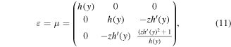
where h'(y) denotes the derivative of function h. The numerical simulations are performed using a two-dimensional finite-difference-time-domain (FDTD) algorithm for anisotropic media [23]. The component lenses of the device have ρ = 4 and the image space is dilated by a factor m = 1/4. The eigenvalues of permittivity and permeability tensors denoted by nxx, nyy and nzz have positive values when the lenses apertures are limited by the singularity points ys. While the values of nxx and nyy, are sub-unitary, the values of nzz are supra-unitary.
At the extremities of the lenses, when approaching the singularity points, the values of nzz reach very large values that are difficult to obtain experimentally. For this reason, numerical simulations have been performed for the ideal case when the lenses radius extends to the singularity points lR = ys, as well as for the case when the lens radius is reduced by 10% from the singularity radius (lR = 0.9ys). The eigenvalues of permittivity and permeability tensors of the transformed media of the reduced radius lenses are limited by the following values: 0.12 < nxx ≤ 1, 0.06 < nyy ≤ 1, and 1 ≤ nzz < 16 for the object lens and 0.03 < nxx ≤ 0.25, 0.03 < nyy ≤ 0.25, and 4 ≤ nzz < 34 for the image lens.
The values less then unity of the diagonalized tensors of permittivity and permeability are mapped with a loss-free Drude-dispersive-material model [23]. The simulation area is terminated in each direction with absorbing boundaries [22]. The simulations are performed using an orthogonal computational grid with a step resolution Δ = λ/40, where λ is the free space wavelength of the sources, and a time step reaching the Courant limit  , where c is the speed of light in free space.
Figure 2 depicts the real part of the Ex field component distribution in the simulation area of (y−z)-plane for the first kind of the proposed optical system having the dilated medium with sub-unitary permittivity and permeability (ε = μ = 1/4) extended over the image focal plane of the device (see figure 1(b)). The device generates for an electric dipole source placed in the object focal point (see the object area-left), a magnified image in the image focal point (see the image area-right). Field distribution depicted in figure 2 is generated by a device having the radius of the component lenses equal to the singularity distance (lR = ys).

Figure 2. The real part of the Ex component of the electric field in the simulation area of the (y−z)-plane for the first kind of the proposed device. The thickness do, di and focal length φo, φi of the object and image lenses as well as the thickness of the absorbing layer a and other dimensions of the simulation area are expressed as multiples of free space wavelength λ of the dipole sources.
Download figure:
Standard image High-resolution imageThe uniform distribution of the electromagnetic field intensity at the output plane of the system ensures an equal contribution to the reconstructed image of the dipole object for all the waves passing through the device. The waves propagating closer to the edge of the system are carrying the information regarding the sub-wavelength details of the object. For a value of the thickness to focal length ratio of the lenses equal to four (ρ = 4), the device has a large angular aperture αs = arccos(1/(ρ+1)) ≈ 780. These characteristics allow the studied system to process waves with high transverse wave vectors and consequently to perform a very accurate image. The accuracy of the reconstructed dipole image is observed in the almost circular phase distribution of the electric field component Ex depicted in figure 2.
Figure 3 depicts the electric field intensity around the image focal point for the first kind of the studied optical systems. Figure 3(a) presents the electric field intensity  along a line parallel to the y-axis passing through the image focal point having a span on the y-axis from −8λ to +8λ, produced by a single electric dipole source placed in the object focal point of the device. Figure 3(b) presents the averaged electric field intensity
  along a line parallel to the y-axis passing through the image focal point having a span on the y-axis from −8λ to +8λ, produced by two incoherent electric dipole sources placed symmetric to the z-axis and object focal point at a distance of λ/2. The averaged intensity was computed for the incoherent dipole sources displaced by λ/2 with respect to their phase shift, which runs from 0 to 2π. The blue and brown graphs in figure 3 correspond to devices having the radius of the component lenses equal to ys and 0.9ys, respectively.

Figure 3. Electric field intensity generated by the first kind of proposed device for device lenses radius  (blue) and lR = 0.9ys (brown). (a) Electric field intensity
  along the line parallel to the y-axis passing through the image focal point. A single dipole source is placed in the object focal point. (b) Averaged electric field intensity
  along the line parallel to the y-axis passing through the image focal point. Two incoherent dipole sources are placed symmetric to the z-axis and object focal point at a distance of λ/2.
Download figure:
Standard image High-resolution imageThe graphs depicted in figures 3(a) and (b) corresponding to the first kind of devices with lenses aperture extended to the singularity limit (blue) and lenses aperture reduced by 10% (brown) are almost the same. The only difference consists of a slightly decrease of the maximum values of the graphs peaks for the device with reduced lenses aperture. This decrease is due to the fact that the optical rays incident on the lenses at their extremities are no longer contributing to the image after the reduction of lenses aperture. This theoretical result shows that an experimental setup, involving media with reasonable optical parameters values, can be realized without considerably altering the optical properties of the proposed device. The graphs depicted in figure 3(a) show that above the side peaks the studied optical system confines the image of the dipole into an area smaller then 2λ. For devices of the first kind having lenses aperture extended to the singularity limit, the full-width at half-maximum of the focal spot computed using the data depicted in the blue graph of figure 3(a) is equal to 1.4λ. For lenses aperture reduced by 10%, the same parameter computed using the data depicted in the brown graph of figure 3(a) is equal to 1.5λ. The graphs depicted in figure 3(b) show that the image of two incoherent dipoles displaced by λ/2 is magnified by approximately four times. The maximum intensity of the image peaks is exceeded by more than three times the maximum intensity of the side peaks, while the minimum intensity between the image peaks almost equalize the maximum intensity of the side peaks. These characteristics of the averaged electric field intensity clearly show the capability of the first kind of the proposed device to provide magnified discernible images of sub-wavelength features.
Figure 4 depicts the real part of the Ex field component distribution in the simulation area of (y−z)-plane for the second kind of the proposed optical system having the dilated medium with sub-unitary permittivity and permeability (ε = μ = 1/4) bounded by the image focal plane of the device (see figure 1(c)). The device generates for an electric dipole source placed in the object focal point (see the object area-left), a magnified image in the image focal point (see the image area-right). After passing through the image focal point, the optical rays continue their propagation into the free space. Field distribution depicted in figure 4 is generated by a device having the radius of the component lenses equal to the singularity distance lR = ys.

Figure 4. The real part of the Ex component of the electric field in the simulation area of the (y−z)-plane for the second kind of proposed device. The thickness do, di and focal length φo, φi of the object and image lenses as well as the thickness of the absorbing layer a and other dimensions of the simulation area are expressed as multiples of free space wavelength λ of the dipole sources.
Download figure:
Standard image High-resolution imageFigure 5 depicts the electric field intensity around the image focal point for the second kind of the studied optical system. Figure 5(a) presents the electric field intensity  along a line parallel to the y-axis passing through the image focal point having a span on the y-axis from −8λ to +8λ, produced by a single electric dipole source placed in the object focal point of the device. Figure 5(b) presents the averaged electric field intensity
  along a line parallel to the y-axis passing through the image focal point having a span on the y-axis from −8λ to +8λ, produced by two incoherent electric dipole sources placed symmetrical to the z-axis and object focal point at a distance of λ/2. The averaged intensity was computed for the incoherent dipole sources displaced by λ/2 with respect to their phase shift, which runs from 0 to 2π. The blue and brown graphs in figure 5 correspond to devices having the radius of the component lenses equal to ys and 0.9ys, respectively.

Figure 5. Electric field intensity generated by the second kind of proposed device for device lenses radius lR = ys (blue) and lR = 0.9ys (brown). (a) Electric field intensity  along the line parallel to the y-axis passing through the image focal point. A single dipole source is placed in the object focal point. (b) Averaged electric field intensity
  along the line parallel to the y-axis passing through the image focal point. Two incoherent dipole sources are placed symmetric to the z-axis and object focal point at a distance of λ/2.
Download figure:
Standard image High-resolution image
The graphs depicted in figures 5(a) and (b) corresponding to the second kind of devices with lenses aperture extended to the singularity limit (blue) and lenses aperture reduced by 10% (brown) are almost the same. The slight decrease of the maximum values of the graphs peaks for the device with reduced lenses aperture can be explained in the same way as for the first kind of devices. The graphs depicted in figure 5(a) show that above the side peaks the studied optical system confines the image of the dipole into an area slightly larger then 2λ. Compared with the dipole image produced by the first kind of devices, the dipole image produced by the second kind of devices has a larger confinement area as well as a decreased maximum intensity. This is due to the fact that the optical rays converging toward the image focal point are only partially transmitted at the interface between the dilated medium and the free space. For devices of the second kind having lenses aperture extended to the singularity limit, the full-width at half-maximum of the focal spot computed using the data depicted in the blue graph of figure 5(a) is equal to 1.6λ. For lenses aperture reduced by 10%, the same parameter computed using the data depicted in the brown graph of figure 5(a) is equal to 1.7λ. The graphs depicted in figure 5(b) show that the image of two incoherent dipoles displaced by λ/2 is magnified by approximately four times. The maximum intensity of the image peaks is exceeded by approximately two times the minimum intensity between the image peaks. These characteristics of the averaged electric field intensity clearly show that the second kind of the proposed device also has the capability to provide magnified discernible images of sub-wavelength features.
4. Conclusions
In this theoretical study, we demonstrate how two transformation optics inspired lenses can be used to build projective optical systems capable of processing the object high spatial frequencies without converting them in evanescent waves. The proposed optical devices project a small area around the object focal point into a magnified area around the image focal point. Two varieties of optical systems were studied, both of them having the image focal point placed in the free space. The first kind of devices have their image focal point placed in a geometrically dilated space having sub-unitary optical parameters. The second kind of devices have their image focal point placed at the interface between a geometrically dilated space and the free space. An absorption layer inserted between lenses is used to ensure a uniform transmission of the device and to provide an even electric field intensity at the output plane of the system for a dipole source placed in the object focal point. Numerical simulations show that both varieties of the proposed optical devices have the capability to provide magnified discernible images of sub-wavelength features.
Acknowledgments
This work was developed by the Company for Applied Informatics using infrastructure obtained through program POSCCE-A2/O2.3.2, project ID SMIS: 44023/2012, and it was partially supported by program POC-A2/221, project ID MySMIS:115641/2017.