

Abstract
Spinal cord injury is a permanent destructive disease that causes devastating neurologic deficits and disability. Long-term complications are associated with low prognosis, mortality, and decreased quality of life. The functional recovery depends on the regeneration of neurons and the growth of medullated axons. Single treatment strategies, including cell transplantation, cannot adapt to a changeable microenvironment. Patients with spinal cord injuries need more effective, long-term, and stable treatment options. Therefore, we investigated the benefit of a combined-tissue engineering strategy by loading homologous bone mesenchymal stem cells (BMSCs) and Schwann cells in three-dimensional (3D) scaffolds. We placed BMSCs and Rat Schwann cells (RSCs) in specific spatial arrangements using cell gravity and the diffusion effect to promote the formation of intercellular connections and cell-directed differentiation. This novel bioengineering system allowed us to control multiple factors, including cell types, cell relative position, and axon growth direction in the scaffold. Our system facilitated motor function recovery by enhancing tissue mimicry and allowing the reconstruction of medullated axons. This new 3D-integrated printing platform is multi-function and can simulate biomimetic tissue using different types of materials and multi-cells scaffolds. We believe that this study can help promote the clinical development and application of 3D printing in the field of regenerative medicine.
Export citation and abstract BibTeX RIS
1. Introduction
Tissue-engineered spinal cord transplants can be used to mimic the anatomical structure and approximate function of native spinal cord tissues [1]. Recently, three-dimensional (3D) printing was evaluated as a precise strategy to fabricate spinal cord mimetic hydrogel scaffolds, which were printed before or simultaneously to stem cell seeding [2]. Most spinal cord scaffolds are printed before stem cell seeding [3–7], however, the bionic scaffolds printed simultaneously are more similar to the anatomical and functional structure of the spinal cord. In particular, 3D bioprinting platforms can control the relative spatial location and distribution of multiple stem cells and biomaterials in the spinal cord scaffolds [8–12]. This 3D approach promotes cell interactions and stem cell differentiation in a manner that mimics the human natural structure [13, 14]. It also allows more precise control of the shape and architecture of more sophisticated biological microstructures compared with other traditional fabrication techniques [15, 16].
However, the strategies to engineer the tissue structures of the central nervous system (CNS) are challenging due to the architectural and functional complexity [2, 8, 17]. The most common scaffolds display homogenous porous channels placed in the same direction [18, 19]. However, channels placed in different directions along the horizontal and vertical axes can reduce the physical and chemical properties of the scaffolds and accelerate the degradation rate [20–22]. On the other hand, due to the transverse and longitudinal selectivity of the channel, these scaffolds may promote an uncontrollable extension of the axons of regenerative neurons. Theoretically, they could compromise the directional regeneration and growth of axons and cause scar tissue tangles [23–27]. To solve this issue, we designed sophisticated 3D-bioprinted scaffolds with single horizontal axis channel combinations to generate functional spinal cord tissues with suitable cytoarchitecture networks.
The combined transplantation of pluripotent stem cells, neurogliocytes, and biological scaffolds shows promise for the development of new therapies for the CNS [28]. For example, the injection of bone mesenchymal stem cells (BMSCs) and Schwann cells (SCs) into an acute spinal cord hemisection improved the motor functional recovery of rats [25, 26]. However, the direct injection of cells in a lesion cavity has many disadvantages, including a lack of structure and support system [29]. Many studies investigated whether the implantation of biocompatible 3D-printed bionic scaffolds combined with BMSCs and SCs could be used as cell transplants and provide mechanical support and axon traction [30, 31]. This opened many opportunities to test new therapeutic options. Structurally, the different regions of the spinal cord are composed of different cell types. The center of the spinal cord is arranged with a high order of spatial distribution. It comprises gray matter surrounded by white matter. Neurons and various support cells are distributed in gray and white matter, respectively [24, 28, 32]. For tissue engineering, the spatial distribution of cellular components is critical to model a spinal cord architecture within engineered tissue constructs [33]. For biomimetic tissue engineering, the recovery of function depends on the proper repair of the spinal cord anatomical structure [33, 34]. The correct microstructure, i.e. the relative spatial distribution of the different cell types, promotes cell differentiation and the reconstruction of the spinal cord structure.
In contrast to other methodologies involving a mixture of BMSCs and SCs with bio-ink, our 3D bioprinting platform allowed us to position the different cells in the scaffold in an optimal localization to promote the reconstruction of an anatomical and microscopic structure closest to the spinal cord tissue. The efficient regeneration of specific tracts of the spinal cord depends not only on the homology of the stem cells transplanted to the host tissue but also their relative spatial position in the scaffold [35–37]. Most bone marrow mesenchymal stem cells differentiate into astrocytes and the rest into microglia cells and neurons. Additionally, the myelin produced by Schwan cells envelopes the axons and secretes cell adhesion molecules, such as NCAM and L1, and myelin-associated proteins, such as MAG, to stabilize the myelin sheath. Various neurotrophic factors are also secreted to strengthen the myelin sheath of the regenerated axons. Moreover, these two types of neural cells can interact to promote differentiation [23, 28, 38, 39].
To this day, it is still a challenge to understand how 3D-printed hydrogel scaffolds promote differentiation. In particular, we observed discrepancies between targeted differentiation and functional recovery after nerve injuries [40, 41]. This could be attributed to the relative spatial position of the cells in the scaffolds, which could limit the clinical application of 3D-printed scaffolds for the treatment of spinal cord injuries [42–44]. We combined these technologies and introduced a 3D bio-printing living platform incorporating BMSCs and RSCs, in which specific cell types can be precisely positioned within a neuro-compatible scaffold. First, a single-layer of BMSCs was positioned on the horizontal plane of the scaffold and a double-layer of RSCs on the longitudinal axial plane of the aperture (as shown in scheme 1). The 1st, 4th, and 7th layers were printed horizontally from left to right with BMSC-loaded printing hydrogel wires (blue). The 2nd, 3rd, 5th, and 6th layers were printed vertically from front to back with RSC-loaded hydrogel wires (green) (supporting material 5 (available online at stacks.iop.org/BF/13/045016/mmedia)). The upper and lower layers of BMSCs and the middle two layers of RSCs surrounded the unidirectional aperture. It was composed of four print wires placed from the front to the back of the single direction aperture and its diameter was between 200 and 300 μm, which was shown to promote axonal growth and avoid fiber scar entanglement. Additionally, we positioned the cells in a relative spatial distribution inside the scaffold channel that mimics the structure of the spinal cord using the cellular gravity of the BMSCs and the cell proliferation of the RSCs. The RSCs were located around the BMSCs in the center to promote intercellular connections and differentiation.
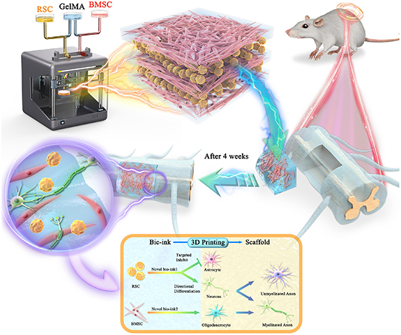
Scheme 1. The experimental strategy for 3D bionic printing scaffold to repair spinal cord injury. Mesenchymal stem cells (BMSCs) and Schwann cells (RSCs) were mixed with GelMA hydrogel respectively and configured with different types and concentration of bio-links. Reverse modeling was carried out according to the performance and requirements of the scaffold, and 3D printing was used to prepare 3D bionic scaffolds suitable for the regeneration of neuronal axial burst buds, extended structure, size and aperture. The two types of cells in the scaffold remain in stable relative position for a long time. The spinal cord half-cut model of SD rat was established (the injured side and the healthy side were compared with normal spinal cord), then the scaffold were implanted into the defect site. The box: directional differentiation strategy for BMSCs and RSCs. After 3D integrated printing, this two types of cells were kept in a relatively fixed position for a long time, and their interaction targeted to inhibit the differentiation of BMSCs into astrocytes and promote the differentiation into neurons. At the same time, RSCs was promoted and influenced by BMSCs cells in the relative position of maximum performance, and most of them differentiated into oligodendrocytes, which were further differentiated into myelin sheath, and wrapped around the axons of regenerative neurons to form a node of Ranvier junction, which is forming the myelinated nerve fibers.
Download figure:
Standard image High-resolution imageIn the long-term, we postulated that the BMSCs would differentiate into neurons with their axons projecting throughout the scaffold channels and the RSCs would differentiate into oligodendrocytes to myelinate the axons. The formation of medullated fibers can accelerate neural electrical signals, create an effective relay across the injury site, and promote the recovery of motor function (figure 1). This novel bioengineering system enabled the control of multiple factors, including cell type, cell relative position, and direction of axon growth within the scaffold. In this study, we provided a novel strategy to enhance tissue mimicry, reconstruct spinal cord conduction pathways, and facilitate repair after injury.

Figure 1. Scaffold characterization. (a) General shape. USWC: unidirectional scaffold without cells; USCC: unidirectional scaffold containing cells. (b) Fourier infrared spectrum reflects the functional group types of substance to infer the composition of the compound. This three wave numbers (3318.68 cm−1 and 470.54 cm−1) represent respectively GelMA hydrogel, LAP and PBS solution. (c) The water content. (d) Young's modulus measures the difficulty of elastic deformation of scaffold material. PSWC: polydirectional scaffold without cells. (e) Rheological proper ties reflects the relationship between deformation and stress under the action of external force. (f) Contact angle measures wettability of the liquid to the surface of the scaffold. (g) Electrical conductivity evaluates whether this scaffold can be used as transmitters of nerve electrical signals. (h), (i) Microstructure of scanning electron microscope. (h): direct lyophilized preparation facilitates the observation of the porous structure of the scaffold; (i): it was prepared by glutaraldehyde fixation method to observe the cell morphology.
Download figure:
Standard image High-resolution image2. Materials and methods
- 1.Scaffold construction: firstly, mix 10% GelMA hydrogel freeze-dried powder (GelMA, SP-BI-G01-2, SunP (Beijing) Biotech. Co., Ltd) with 0.25% LAP, and respectively add 1 × 10⁶ ml−1 BMSCs and RSCs into it for bio-printing ink. Debug 3D printer (SUNP Biomaker, SunP (Beijing) Biotech. Co., Ltd) to achieve nozzle temperature 28 °C, platform temperature 10 °C, printing speed 3 mm s−1, ultraviolet disinfection and sterilization. Place the finished bio-ink into the injection syringe with a needle size of 23G (internal diameter of about 350 µm). Start the printing process. After printing, place the 3D bracket at a distance of 2–3 cm from the blue light source (405 nm) and crosslink it for 15 s. Then the medium was put into, medium was added for routine culture, and 5%CO2 was put into an incubator at 37 °C for routine culture.
There are four types of scaffold.
- PSCC: polydirectional scaffold containing cells (figure 2(a)).
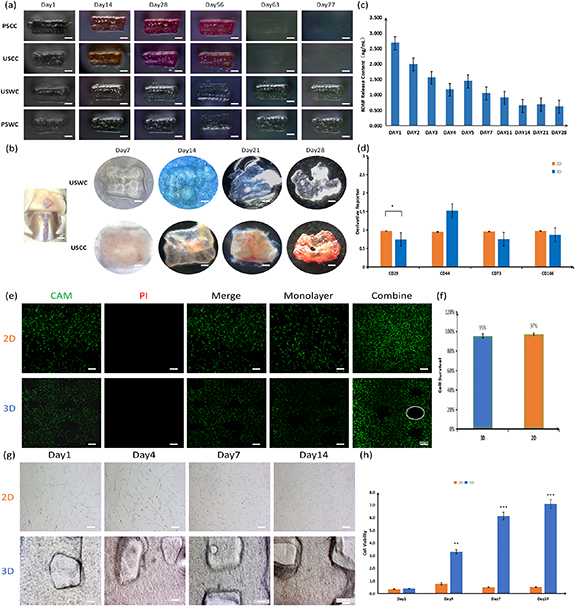
Figure 2. Biological behavior of scaffold. (a) Degradation of scaffolds in vitro. There are four types of 3D-printed scaffolds were placed in the medium and cultured in the incubator for 11 weeks until the degradation of one type of scaffolds was complete. (b) Degradation of scaffolds in vivo. There are two types of scaffolds were transplanted to the sites with the fastest degradation rate in vivo in order to observe the stable existence of scaffolds after four weeks. (c) Release curve of BDNF factor evaluates the ability of sustained-release to release nutrient factors stably within four weeks. (d) PCR of BMSCs in seven days after cultivate to evaluate whether BMSCs has cellular dryness. (e) Calcein-AM/PI dyeing in 24 h after printing detects the cell viability of the 3D-printed scaffold; living cells: CAM (green), dead cells: PI (red), monolayer: scanning of single layer; (f) Image J statistical figure of living and dead cells. (g) The morphology and density of proliferating cells by light microscope. (h) CCK-8 statistical curve analysis the proliferation of cells in the scaffold during 14 days.
Download figure:
Standard image High-resolution image
- 2.Homologous stem cell extraction: the ophthalmic forceps lifted the skin of the rat along the groin, the ophthalmic scissors cut the skin of the groin, exposed the muscles of the leg, and cut the rat thigh from the joint. Remove the soft tissue attached to the bone surface and place it in another sterile Petri dish. Wash with sterile phosphate buffer saline (PBS). Ophthalmic scissors cut off the epiphysis at both ends to expose the bone marrow cavity, place it in a 10 ml sterile Petri dish containing 10% fetal bovine serum in a volume of fresh DMEM complete culture medium, take out a 1 ml syringe, use forceps to lift one end of the bone, and use the syringe Aspirate the complete culture fluid to rinse the bone marrow cavity into another Petri dish, flush out the bone marrow from a section of bone marrow cavity, repeat three times, then flush out the bone marrow in the opposite direction, repeat three times. Stop until the marrow cavity flushing fluid becomes clear. Pipette the cell suspension to disperse the cells, collect the bone marrow suspension in a 15 ml centrifuge tube, and centrifuge at 1000 r min−1 at room temperature for 5 min. After centrifugation, the supernatant was removed, resuspended with 6 ml of complete culture solution, and gently pipetted to make a single cell suspension, transferred to a 25 cm2 culture flask, and gently shaken; placed at 37 °C, the volume fraction of 5% CO2 incubate in a saturated humidity incubator. After 24 h, under the microscope, it can be seen that the cell concentration is extremely large, and the red blood cells in the all-spherical rat bone marrow, such as accumulated sand, are suspended in the culture medium and a small amount of red blood cells aggregate with each other. Change the fluid to remove floating blood cells, and then change the fluid every two or three days until the proliferation reaches fusion. After about seven days, the cell morphology and growth were observed under an inverted microscope. The number of adherent cells increased significantly, and the fusion reached 80%–90%, and the cells could be passaged. One male two month-old mouse was intraperitoneally anesthetized with 1% pentobarbital sodium (50 mg kg−1), and the distal sciatic nerve was cut off under sterile conditions. After seven days, the pre-denatured sciatic nerves of 20–25 mm were separated and extracted, washed three times with PBS, placed in D-Hanks, and the outer nerve membrane was stripped off. The obtained tissue was cut to a size of about 1 mm3, and 0.05% collagenase-dispase complex digestion solution was separated and digested at 37 °C for 3–5 h, 2000 r min−1, centrifuged for 10 min, and the supernatant was discarded. Then resuspend in DMEM medium containing 10% fetal bovine serum (FBS), centrifuge at 900 r min−1 for 5 min, and discard the supernatant. Finally, it was made into a single cell suspension with a DMEM medium containing 10% FCS and inoculated in a Petri dish coated with 10 µg ml−1 laminin (37 °C, 2 h). Incubate at 37 °C, 5% C02 for three to five days.
- 3.Scanning electron microscopy: the hydrogel sample prepared above was dehydrated for 24 h by vacuum freeze-dryer. The thin slices were placed in a vacuum chamber, uniformly coated with a thin layer of gold, and then the thin slices were loaded into a field emission scanning electron microscope for morphological imaging.
- 4.Characterization of physical and chemical properties: the composition of the scaffold was determined by Fourier transform infrared spectroscopy. Young's modulus was measured by dynamic mechanical analysis (DMA) in 37 °C. During DMA testing, we use a liquid nitrogen device to cool down the furnace to balance the heating, which can maintain the stable temperature of 37 °C. The rheological properties were measured by oscillating stress scanning and frequency scanning through the rotary rheometer in 37 °C. The contact angle was determined by the contact angle tester in 37 °C. The resistivity was measured by four probe method in 37 °C. The water content of the scaffold was measured by differential scanning calorimetry and thermal gravimetric analysis between 20 °C and 140 °C.
- 5.Calcein-AM/PI cell staining: add 200 μl of DMSO to a tube containing 200 μg of calcein-AM powder and dissolve by pipetting. Return the calcein-AM storage solution and PI storage solution to room temperature before use. Add 10 μl of calcein-AM storage solution and 15 μl of PI storage solution to 5 ml of PBS (−) and mix to make a working solution. At this time, the concentration of calcein-AM is 2 μmol l−1, while the concentration of PI is 4.5 μmol l−1. After the preparation of AM and PI staining solution, the cells were washed with PBS for three times, and the staining solution was directly added for staining. Remove the supernatant and add PBS (−) to prepare a cell suspension (105–106 ml−1 is appropriate). Repeat step 2 and step 3 several times to eliminate the esterase activity in the medium. About 100 μl of the staining working solution was mixed with 200 μl of cell suspension and incubated at 37 °C for 15 min. At the excitation wavelength of 490 ± 10 nm, yellow-green fluorescent live cells and red fluorescent dead cells were simultaneously observed. In addition, the dead cells were observed separately with an excitation wavelength of 545 nm.
- 6.CCK8: the samples to be tested in each group were washed with PBS for three times, and the mixture of culture medium and test solution was added to each sample (1 ml BMSCs complete medium +0.1 ml CCK8). Incubate at 37 °C for 2 h in darkness of light, and take the cultured culture. The nutrient group was added to the 96-well plate (110 l for each well), and the optical density (OD) value was read by the marker 450 nm. Blank pores containing cells were used as blank controls. And three-times independent replicates were set at each time point (one, four, seven, fourteen days) in each group. The standard curve calculates the number of cells in each sample.
- 7.The determination of PCR: the total RNA of each group of cells was extracted by the Trizol method, and reverse transcription was performed according to the instructions of the reverse transcription kit to obtain cDNA. Reaction system: SYBR Premix Ex Taq II (Tai RNase Plus) (2×) 10 μl, PCR Forward primer (10 μmol l−1) 0.8 μl, PCR Reverse primer (10 μmol l−1) 0.8 μl, template 2 μl, dH2O 6.4 μl. Reaction conditions: 95 °C 3 min; 95 °C 1 min, 60 °C 30 s, 72 °C 5 min, 40 cycles of amplification. Use 2−△△Ct method to analyze the test results. The primers were designed by ABI's Primer Express Software v2.0 and synthesized by BGI.
- 8.Brain-derived neurotrophic factor (BDNF) factor release experiment: we added 100 µl of increasing concentration of standard solution (2000 pg ml−1, 1000 pg ml−1, 500 pg ml−1, 250 pg ml−1, 125 pg ml−1, 62.5 pg ml−1, and 31.2 pg ml−1) and 100 µl of sample diluent for the control well into 96-well plates. We collected 100 µl supernatant at different time points and added to the 96-well plate. We sealed the plate with sealing paper and incubated it at 37 °C for 90 min. We removed the liquid from each well, blotted the wells dry with absorbent paper. We then added 100 µl anti-BDNF antibody to each well, sealed the wells with sealant, and incubated the plate at 37 °C for 60 min. For the washing version of the protocol, we removed the liquid from the wells, added 300 µl PBS, let it soak for 1 min, discarded the cleaning liquid, and blotted the wells dry with absorbent paper three times. We, then, added 100 µl ABC test solution, sealed the wells with sealing paper, and incubated the plate at 37 °C for 30 min. We, then, washed the plate as mentioned above five times. We added 90 µl Tetramethylbenzidine (TMB) chromogenic liquid to each well. We sealed and incubated the plate at 37 °C in dark for 30 min. We added 100 µl TMB termination liquid to each well and read the OD values at 450 nm. We calculated the OD values of each standard well and drew the standard curve. We calculated the BDNF content for each condition according to the standard curve and performed a statistical analysis for the BDNF factor release amount at each time point.
- 9.Scaffold degradation experiment: we placed the 3D printing scaffold in a petri dish for continuous observation for 28 + 7 days and used a stereoscope to take pictures for observation.
- 10.Animal model construction: we used healthy adult female SD (Sprague-Dawley rats) weighing 200–300 g. We anesthetized the rats intraperitoneally with 0.3% pentobarbital (30 mg kg−1), cut the skin on the back to expose the hemispine muscles and tendons on both sides of the back spine. The hemispine muscles on both sides below L1 are attached to the midline with the tendons. We counted the marks up to T10 in sequence, made a mark at the midpoint of the intervertebral space between T10 and 11, and used a finger to pinch the position from the abdomen as far as possible to increase the intervertebral space. We, then, fixed your head with your thumb and index finger tail. The other hand holds a surgical knife with the blade facing the side. We placed the tip of the knife parallel to the mark and entered the intervertebral space. The vertical force quickly reached the vertebral body and we tilted the handle 30° to the uncut side. We lifted the knife quickly and cut the spinal cord. We found that the paralysis after hind limb twitching was the host model. We sutured the incision, placed the rats under natural light illumination, and kept them dry. We performed all animal experiments according to the Guiding Principles for the Care and Use of Vertebrate Animals in Research and Training and approved by the Ethics Committee for Laboratory Animals of Institute of Radiation Medicine, Chinese Academy of Medical Sciences (IRM-DWLL-2019125).
The experiment was divided into five groups.
- Sham group (SG): only T9 lamina was bitten without spinal cord injury;
- Control group (CG): no transplantation is performed after spinal cord injury;
- Simple scaffold group (SSG): the simple scaffold without any cells;
- Hydrogel group (HG): hydrogel encloses two types of cells;
- Printed scaffold group (PSG): 3D-printed spinal cord scaffold with two kinds of cells for transplantation.
Sequence and primer design.
| Name | Primer (5' to 3') | Tm |
|---|---|---|
| CD29-F | TTGTTGGTCAGCAGCGCATA | 59 |
| CD29-R | ATCCGTGGAAAACACCAGCA | — |
| CD44-F | CCCCACATGCTACAAGCACA | 59 |
| CD44-R | TCTTCCCCTGCCATTCATTC | — |
| CD73-F | TGCAGCCATCAAAGCAGACA | 59 |
| CD73-R | TGAGCGGAGCCATTCAGGTA | — |
| CD166-F | CTTGCCGTCTGGTTTTCTGC | 59 |
| CD166-R | TCTGCAAGGCATGACAATGG | — |
| Actin-F | CCCATCTATGAGGGTTACGC | 59 |
| Actin-R | TTTAATGTCACGCACGATTTC | — |
- 11.Histologic staining: we placed the slices, in turn, in xylene I for 10 min, xylene II for 10 min, anhydrous ethanol for 15 min, anhydrous ethanol II for 5 min, 95% alcohol for 5 min, 90% alcohol for 5 min, 80% alcohol for 5 min, 70% alcohol for 5 min, and distilled water to wash. We stained the slices with Harris hematoxylin for 3–8 min, washed them with tap water, placed them in 1% hydrochloric acid and alcohol for several seconds, and rinsed them with tap water. We, then, placed them in 0.6% ammonia until they turned blue and washed them with tap water. We stained with eosin for 1–3 min. We placed the slices in order in 95% alcohol I for 5 min, 95% alcohol II for 5 min, anhydrous ethanol for 15 min, anhydrous ethanol II for 5 min, xylene I for 5 min, xylene II for 5 min and dried them slightly with a gum sealer. We used a microscope for image acquisition and analysis.
- 12.Immunofluorescence staining and confocal observation: we washed twice with PBS or 0.9% NaCl for 3 min each time and drained the liquid. We washed on a shaker or manually several times. In a six-well plate, we stained with 0.5 ml Hoechst 33258 5 min. We washed twice with PBS or 0.9% NaCl for 3 min on a shaker or manually. We placed the slice on a glass slide, dropped a anti-quenching mounting solution, covered them with a clean coverslip, and tried to avoid air bubbles. We detected the blue nuclei using fluorescence microscopy. The excitation wavelength is around 350 nm and the emission wavelength is around 460 nm. The absorption spectrum and emission spectrum of Hoechst 33258, the peak on the left is the absorption spectrum and the peak on the right is the emission spectrum. Antibody information is follow.
- 13.Basso Beattie Bresnahan (BBB) score: we placed the animals on a circular platform with a diameter of 2 m and measured the walking and limb activity scores of their hind limbs in three parts. The second part is 8–13, we judged the gait and coordination function of the hind limbs. In the third part, we used 14–21 points to evaluate the fine movements of the paws. We, then, used the three experimental animals with a full score of 21 points to measure BBB scores three days before and after the operation and one week, two weeks, and four weeks after the operation. We performed a statistical analysis using Student's t-tests.
- 14.Ramp test: we performed inclined plate tests one day before surgery and one, three, and seven days after surgery, according to the literature [11]. Before the test, we placed the rats on an inclined plate with an inclination of 30°. After 1 min of acclimation, we used 5° as a unit to continuously increase the inclined plate. If the rats persisted in this inclination for 5 s three times, we continued to increase the angle after a resting period of 1 min and until the rats could not persist for 5 s three times. We recorded the maximum angles that the rats could hold for 5 s three times.
- 15.Statistical analysis: we repeated all of the experiments at least three times. We presented the data as the mean ± SD (standard deviation). We used Student's t-test to compare the means. We defined the two-tailed p-values for statistical significance as p < 0.05. We performed a statistical analysis using GraphPad Prism 8.0 software (GraphPad Software 8, San Diego, CA).
Reagent company and code.
| Name | Company | Number |
|---|---|---|
| Anti-GD2 antibody | ABCAM | Ab68456 |
| Anti-SOX10 antibody | Bioss | Bs-6449R |
| Anti-MBP antibody | Affinity Biosciences | Af4085 |
| Anti-GFAP antibody | Abcam | Ab190288 |
| Anti-NeuN antibody | Abcam | Ab104224 |
| Anti-NF-L antibody | Abcam | Ab72997 |
| Anti-beta III antibody | ABCAM | Ab68193 |
| DAPI | Beyotime | C1005 |
3. Results
3.1. Characterization of the 3D-integrated printing platform bionic spinal cord stent
The 3D-integrated printing platform designed a variety of scaffolds prepared by new bioinks, including simple 3D scaffolds (figure 1(a), USWC) and two-cell scaffolds (figure 1(a), USCC). We observed the newly designed scaffolds under a stereoscope. The scaffolds were composed of GelMA and LAP and stored in a PBS solution (figure 1(b)). The initial temperature of the support was 30 °C and its temperature curve began to deviate from the baseline. The epitaxial initial temperature was 50 °C, which was the temperature with the best repeatability and stability for the material. The temperature of the spinal cord tissue in vivo was 37 °C and the local temperature rose slightly with the occurrence of local inflammation within the injury. The local temperature was slightly higher but always remained below 50 °C. Thus, the stents implanted in the spinal cord were in a stable temperature range. The 5% decomposition temperature was 53 °C, the 10% decomposition temperature was 57 °C, and the epitaxial termination temperature was 125 °C. After raising the temperature to 140 °C, 10% of the material was still preserved and we determined that the heat stability of the scaffold was appropriate (figure 1(c)).
The unidirectional aperture of the horizontal axis (US) and the multidirectional aperture of the horizontal and vertical axis (PS) were significantly different in terms of material rigidity (figure 1(d)). Under the simulated in vivo condition at 37 °C, the rigidity of the US remained unchanged while the rigidity of the PS gradually decreased, indicating that the rigidity performance of the US was better than that of the PS. We also observed a close temporal effect of material variation with frequency and stress (figure 1(e)). The energy storage modulus (i.e. the elastic modulus) remained unchanged with a gradual increase of frequency (0.01–100 Hz), indicating that the elastic magnitude was stable in case of deformation. The variations in the loss modulus (i.e. the viscosity modulus) indicated that the viscosity first decreased and then increased after a deformation.
At 37 °C, the contact angle of the scaffold was within the range of 76°± 10%, indicating good wettability and hydrophilicity (figure 1(f)). The resistance of the stents was an average of 6 Ω m, which was appropriate as the resistance of normal nerve tissue remains between 5 and 10 Ω m (figure 1(g)). These conductive properties are beneficial to the regeneration of electronic signals between neurons [19, 34, 38]. The pores of the freeze-dried scaffold had a uniform size of ≈200 m (figure 1(h1)). As the materials are swelling in the hydrated status, the pores of 3D printed hydrogel will be changed. The pore size around the three-layer cellular structure (one horizontal layer of BMSCs and two vertical layers of RSCs) was conducive to the regeneration of neurons, the extension of axons, and the inhibition of glial scar tangles. The aperture surface and the scaffold interior were composed of a loose network structure (figure 1(h2 and 3)), which provided a wide living space for two cells in a fixed position. We observed that the BMSCs on the surface of the scaffold showed the characteristics of long-spindle structures (figure 1(i)1). We also found long-spindle cell structures inside the scaffold, indicating that the cells were evenly distributed on the surface and the inside of the scaffold (figure 1(i)2).
In conclusion, the scaffolds showed stable mechanical performance, heat resistance, and rigidity under the simulated internal temperature conditions. These conditions simulated the force and deformation of the spinal cord in vivo and created appropriate physiological conditions for the cells. Similarly, the scaffolds displayed a suitable electrical conductivity which was conducive to material exchange. Finally, the loose network structure facilitated the uniform distribution of the cells and the maintenance of cell morphology.
3.2. Biological behavior of the scaffolds
In figure 2(a), we printed four types of scaffolds to compare the biodegradation rates: a unidirectional aperture scaffold carrying cells (USCC), a polydirectional (horizontal and longitudinal) aperture scaffold carrying cells (PSCC), a unidirectional aperture scaffold without cells (USWC), and a polydirectional (horizontal and longitudinal) aperture scaffold without cells (PSWC). We designed a unidirectional aperture scaffold with a tight longitudinal connection and no gaps, which was more resistant to compressive deformation than a polydirectional aperture scaffold (as shown in figure 1(d)). Additionally, the degradation of the scaffold can cause a new round of secondary injuries. The degradation rates of the four stent groups were different in our in vitro culture (figure 2(a)). We compared the USCC, PSCC, USWC, and PSWC models. The USCC and PSCC displayed a low degradation rate and were highly stable, which confirmed that the mechanical properties of the unidirectional aperture scaffolds are better than the polydirectional aperture scaffolds (figure 1(d)). In terms of cell loading, we compared the USCC with the USWC and the PSCC with the PSWC. The latter showed a low degradation rate and was highly stale, suggesting that the cells and the small molecules interacted with the scaffolds and promoted their degradation in vitro. However, we did not observe any significant difference at 28 days. The degradation rate was faster in the presence of more blood vessels. We transplanted the USWC and USCC subcutaneously in rats. The general structure of the two scaffolds was maintained after 28 days, especially for the USCC (figure 2(b)). We also found that the USCC was irrigated by more subcutaneous blood vessels. The strong ability of the USCC to maintain its gross structure in vivo may be related to the formation of connections between the cells inside the scaffold and the local cells. These findings lay the theoretical and developmental foundation for the maintenance of the gross anatomical morphology of the spinal cord after the local transplantation of the USCC. The biological scaffold contained BDNF that was released continuously and a single release dose maintained the biological effect even at 28 days (figure 2(b)). The trophic factors would not collect locally after the stent implantation into the spinal cord because of their continuous release and the circulation of cerebrospinal fluid. The determination of a single release amount in vitro could help evaluate the effective concentration of nutrient factors in the injured area even with continuous replacement. The appropriate sustained-release ability of the stents depends on their stability (figure 2(a)).
A large number of cells survived in the printed scaffolds. A monolayer scanning revealed that the number of cells in the 3D scaffolds was relatively small compared with the two-dimensional (2D) scaffolds. The number of cells also did not significantly change after stacking the layers. This indicated that the cells were evenly distributed on the inside and outside of the scaffolds when their number remained consistent (figures 2(e) and 1(h)). Under normal conditions, the survival rate of the cells co-cultured with biomaterials was satisfactory. In this study, we showed that the survival rate of the cells in the integrated printed scaffolds was as high as 95% and the biocompatibility was excellent (figure 2(f)). We did not observe any significant difference in cell proliferation between the two groups on day 1 probably because of the adaptive characteristics of the cells (figures 2(j) and (h)). In the 2D group, the number of cells was lower on day 7 than on day 4 and remained almost the same between days 7 and 14. The growth of the 2D-cultured cells showed an obvious bottleneck effect. The 2D space and inter-cell competition inhibited cell proliferation. However, we did not find any significant inhibition of the cell proliferation in the 3D group. The number of cells was significantly higher in the 3D group than in the 2D group at the beginning of day 4, indicating that the 3D-printed scaffolds were more suitable for cell proliferation. Similarly, BMSCs maintained an appropriate dryness inside the scaffolds and only the number of CD29 was statistically significant ((*<0.05), figure 2(d)). BMSCs tended to have lower migration abilities in the 3D scaffolds. We observed that many cells gathered around the scaffolds and inside the aperture. This increased the size of the cells and the probability of differentiation into neurons (scheme 1).
In conclusion, the degradation rate of the scaffolds in vitro and in vivo showed good stability, maintained a slow release of small molecules, and met the needs for spinal cord transplantation. Its excellent biocompatibility accelerated the cell proliferation rate, retained the differentiation potential of the stem cells, maintained cell dryness, and reduced the tendency of stem cells to migrate.
3.3. Bi-cells placed in a relatively fixed position in the biomimetic spinal cord promoted neuronal differentiation and the directional growth of axons
We observed the overall morphology of the 3D printed scaffolds after seven days of culture. The top view showed the diameters of the BMSC and RSC layers surrounded by a cluster of scaffolds (figure 3(a)1). The printing hydrogel wires on both sides of the aperture contained a large number of BMSCs and RSCs with fixed relative positions (figure 3(a)2). The frontal view showed that the pores were regularly distributed and a large number of double cells were spread around them (figure 3(a)3). Additionally, several cells migrated from the printing silk to the middle of the pores to start their differentiation into neurons (figure 3(a)4).

Figure 3. Cell distribution and differentiation in 3D-printed scaffold. (a) The spatial distribution of BMSCs and RSCs in the scaffold in seven days after printing; in the transection, we observed the difference of cell distribution between the printed filament and the middle pore diameter. In the vertical section, we observed a large number of BMSCs and RSCs around the pore diameter. BMSCs: GD2 (green), RSCs: Sox 10 (red). PSG: 3D printing scaffold group, HG: GelMA hydrogel group. (b) The density of cell differentiation and axonal growth in 28 days. It was observed that a large number of neurons and axons directionally distributed. Neuron: NeuN (green), axon: β-III Tubulin (red). (c) Cell differentiation and axonal growth from 7 days to 28 days. Along the aperture channel, neurons and axons became denser and longer in length.
Download figure:
Standard image High-resolution imageThe scaffolds placed at the relative spatial position of the biomimetic spinal cord were continuously cultured for four weeks and we observed cell differentiation in the aperture channels (figure 3(b)). The scattered BMSCs differentiated into neurons after the first week and the regenerated axons showed a certain directional tendency. We also observed interactions between the adjacent axons. During the second week, several neurons were regenerated. Their axons extended along the direction of the scaffold aperture and connected with neighboring neurons after co-localization. During the third week, we observed several regenerative neurons and their distribution also followed the direction of the aperture. The extending axons connected with neurons and extended further away. During the fourth week, a large number of regenerative neurons and their protruding axons grew and extended along the direction of the apertures. We also observed a large number of neurons and axons in the top and elevation view of the scaffolds. The growth of the neurons and the extension of axons also followed a specific direction in local amplification (figure 3(c)1, 2).
In conclusion, the integrated 3D-printed scaffolds maintained the relative spatial position of the two cell types, which greatly improved the neuronal differentiation of BMSCs. The unidirectional aperture channels (≈200 m) promoted the directional growth of neurons and the extension of axons. These results lay a foundation for the use of integrated 3D-printed scaffolds for spinal cord transplantation as they could facilitate the connection of the upper and lower normal tissues across a damaged area and promote the recovery of motor function.
3.4. In vivo experiment and motor function evaluation
The mechanical properties and electrical conductivity of the scaffolds were stable and satisfactory. They promoted material exchange and the sustained release of small molecules. They also showed good biocompatibility, accelerated the proliferation of stem cells, maintained cell dryness, and reduced migration. The bionic spatial distribution of the cells in the scaffolds promoted the neuronal differentiation of BMSCs and allowed a directional distribution and growth of axons. We placed the stents (figure 4(a)) and waited 24 h to perform the subcutaneous transplantation in rats to avoid immune rejection. After four weeks of continuous observation (figure 4(c)), we noticed that the initial inflammatory response reduced gradually and almost disappeared during the fourth week (figure 4(c), black arrow). This indicated that the immunogenicity of the scaffolds was extremely low. After four weeks, we observed a certain correlation between the transplanted scaffolds and subcutaneous vessels. However, there needs to be further experimental results to confirm the association between vascular formation and scaffolds (figure 4(d)). This was consistent with the degradation of the scaffolds we noted in vivo (figure 2(b), USCC). This also confirmed the presence of interactions and adaptive connections between the scaffolds and the local tissues.

Figure 4. Experiment in vivo and motor function evaluation. (a) Experimental design. Sham group (SG): remove T9 lamina without spinal cord injury; control group (CG): no transplantation after spinal cord injury; simple scaffold group (SSG): simple scaffold without any cells; hydrogel encapsulated two types of cells; printed scaffold group (PSG): 3D-printed spinal cord scaffold with two types of cells for transplantation. (b) Pre-culture the scaffold for 24 h to adapt the loaded stem cells to the scaffold environment; (c) preparation of T9 spinal cord injury model and implantation of scaffold, red arrow: central vein of spinal, white arrow: bionic scaffold; (d) there is certain association between subcutaneous vessels and scaffold, but it has not been clearly confirmed. Green arrow: subcutaneous vessels; (e) BBB score; (f) Ramp test; (g) HE staining of subcutaneous tissue after scaffold implantation. Black arrow: inflammatory cells (n = 6).
Download figure:
Standard image High-resolution imageFor the in vivo experiments, we divided the animals into six groups. The SG group included animals with bitten T9 lamina without spinal cord injury. The other groups suffered spinal cord injuries. The CG group did not undergo transplantation. We used simple scaffolds without cells in the SSG group, hydrogel scaffolds with two cell types in the HG group, and 3D-printed scaffolds with two cell types in the PSG group.
We verified that the stents did not induce any immune rejection and conducted the spinal cord modeling 24 h after the printing and the placement. The vertebral lamina was bitten to preserve the central vein (figure 4(b)1, red arrow) and the spinal cord was cut in half for the stent transplantation (figure 4(b)2, white arrow). The BBB score of the SG first decreased and returned to normal after four weeks of continuous exercise evaluation. This may be due to local stress response and inflammatory stimulus which were gradually recovered after absorption and adaptation. The injury CG presented paralysis with little improvement. The animals in the PSG group showed the best recovery compared to the HG group. The SSG group showed the worst recovery.
In the inclined plate experiments, the SG rats displayed a strong grip and climbed quickly. In the CG paralysis group, the animals attempted to move but showed essentially no movement function and quickly fell to the bottom. The SSG rats displayed a very weak grip and hind limb movement, which could only be sustained on an inclined board for a few seconds. The HG rats displayed a strong grip and a prolonged maintenance time but still showed some deficiency in their hind limb movement ability. The PSG rats showed a strong grip on the ground and hind limb movement ability on the inclined board. They were also able to climb without slipping. Moreover, the PSG rats moved their limbs in a coordinated manner without any obvious hindrances.
The use of joint tissue-engineered scaffolds during cell transplantation showed a better recovery of motor function after spinal cord injury compared with pure stands. The spatial location of bionic spinal cords with 3D-printed scaffolds containing two types of cells was better compared to hydrogel scaffolds because two cells in a relatively fixed position can interact with each other and regulate greatly the direction of differentiation. This resulted in an increased number of neurons and promoted the directional extension of axons across the bridge of the damaged area (figure 3(c)1 and 2).
3.5. Stents maintained the spinal cord anatomy and promoted neuronal regeneration
The SG rats displayed complete spinal cord structures with visible gray and white matters. The neurons were large with a polygonal shape and a reddish cytoplasm. The nuclei were round, vacuolated, located in the center of the cytoplasm, and with visible nucleoli. We also observed abundant Netensite in the cytoplasm (figure 5(a)).
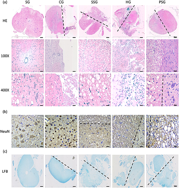
Figure 5. Immunological evaluation in the area of spinal cord injury. (a) HE staining: the gross structure of the spinal cord is compared with the site of injury. 100×: local structure of spinal cord of scaffold. 400×: the photograph of the morphology and number of cells (e.g. neurons) in the spinal cord or scaffold. (b) Immunohistochemical staining of neurons was to observe the morphology and number of neurons (NeuN) in the spinal cord tissue, scaffold or the joint. (c) LFB: myelin staining (blue) was to observe the gross structure of the spinal cord, which was mutually confirmed with HE staining. Black dotted line: the boundary between normal tissue and intervention (n = 6).
Download figure:
Standard image High-resolution imageThe spinal cord structure of the CG rats was intact and the injured site no longer visible (figure 5(b)). The number of neurons in the damaged gray matter was decreased. We also observed a decreased cell volume, an irregular morphology, a nuclear contraction, and a loss of nissanite. The number of microglia cells around this area was increased.
The spinal cord structure of the SSC rats was relatively complete when compared with the SG rats (figure 5(b)). We observed shrinkage of the neurons in the gray matter. The cell volume of the neurons was decreased and they displayed irregular shapes, unclear nucleus and nucleoli. The nistenite also disappeared. The injured sites were filled with scaffolds. The gross structure was slightly smaller than that of the healthy side and a very small number of neurons and microglia cells remained visible. The stents alone maintained the general shape of the spinal cords but did not promote the regeneration of neurons.
The HG rats displayed irregular and reduced spinal cord structures when compared with the SG rats (figure 5(b)). We also observed that the central vein shifted to the healthy side. The healthy side tissue was squeezed in the HG rats probably due to the swelling effect of hydrogels. The damaged side was irregularly filled with hydrogel, a large number of BMSCs and RSCs, and a very small number of neurons and surrounding microglia cells. Hydrogels alone did not support the structure of the spinal cord and the cells could not effectively differentiate into neurons.
The spinal cord structure of the PSG rats was intact and slightly smaller than that of the SG rats (figure 5(b)). Normal neurons were visible at the junction of the scaffolds on the damaged and healthy sides. Neurons and microglia cells were also visible in the scaffolds. The integrated scaffolds containing the two cell types did not only effectively maintain the gross structure of the spinal cord but also did not damage the neurons on the healthy side of the bridge. The scaffolds showed good biocompatibility (figures 2(e) and (f)) and very low immunogenicity (figure 4(c)).
Further identification of the neurons inside the scaffolds showed that the neurons were normal in shape in the SG group but in a state of densification in the CG group (figure 5(c)). We observed very few neurons in the scaffolds of the SSG group, only a few neurons in the HG group, and a large number of neurons in the PSG group. The two cell types were more likely to differentiate into neurons in PSG rats than in HG rats.
3.6. Cell differentiation and formation of myelinated nerve fibers after scaffold transplantation
After the stent transplantation, the glial scar was replaced to support the local structure of the spinal cord (figures 6(a) and (b)) and the cells inside the scaffold kept proliferating and differentiating in situ. The BMSCs and RSCs were not visible in the damaged area of CG rats (figure 6(a)). We found a small number of BMSCs in the lower right part of the SSG rats. Considering that the BMSCs adjacent to the normal spinal tissue migrated into the stent, we only found very few RSCs. In HG rats, the BMSCs and RSCs were mostly in the lower left part. The disorderly arrangement of cells did not allow an effective extension of the axons of differentiated neurons. On the other hand, we found a large number of BMSCs and RSCs in the PSG group. They were uniformly distributed in the scaffold region, laying a foundation for the next stage of differentiation.

Figure 6. Immunofluorescence staining of the local area of spinal cord injury. (a) The interaction between a certain number of two types of cells (bone marrow mesenchymal stem cells, BMSCs; Schwann cells, RSCs) fixed in the relative spatial position in the scaffold. BMSCs: GD2 (green), RSCs: SOX10 (red). (b) BMSCs differentiated into astrocytes (GFAP, red) and RSCs differentiated into oligodendrocytes (MBP, green). White dotted line: the boundary between the normal spinal cord and scaffold. (c) The relative spacial position of this two kinds of cells promotes the regeneration of neurons (NeuN, green) and the directed growth of axons (β-III Tubulin, red). The area of white dotted line: 3D-printed scaffold. (d) The cells at different positions differentiate in different directions. One is co-localization of neurons (NF-200, green) and Schwann cells (SOX10, red); another is co-localization of neurons (NeuN, green) and myelin sheaths (MBP, red). (e) The microscopic structure of the myelin sheath (MBP) enclosing neurons (NeuN), which formed myelinated nerve fibers to promote the conduction rate of nerve electrical signals. Write arrow: the myelin sheath surrounds the nerve fibers (n = 6).
Download figure:
Standard image High-resolution image
We did not visualize neurons and axons in the CG group (figure 6(b)). Only a small number of neurons and axons were visible in the SSG group, considering the differentiation of nerve cells migrating into the scaffolds. We also observed a small number of neurons in the HG group but axons were not visible. Compared with the SSG rats, the approximately same number of neurons displayed fewer axons, indicating that the disorderly arrangement of cells and undirected pore diameter channels did not promote the extension of axons. We observed a large number of neurons and axons arranged in bundles in the PSG group and the direction of growth was consistent with the direction of the pore diameter. The cell arrangement and the single-direction pore diameter channels, which simulated the spatial position of the spinal cord, were suitable for the regeneration of neurons and the extension of axons.
Astrocytes display both inhibitory and promoting effects on regeneration in glial scars. Their inhibitory impact is, however, greater than their promoting influence. Using scaffolds with an inappropriate pore size and number of channels can cause glial scar entanglements, interrupt the remaining upstream and downstream spinal cord tissues, destroy the microenvironmental homeostasis, inhibit the regeneration of neurons, and hinder the axial burst bud and extension. On the other hand, oligodendrocytes differentiated from SCs secrete neurotrophic factors, improve the local microenvironment, and promote neuron regeneration. We observed a large number of astrocytes in the CG group but very few oligodendrocytes (figure 6(c)). The number of astrocytes and oligodendrocytes in the SSG and HG groups was small compared with the CG rats. We observed very few scattered astrocytes in the PSG group and no tangles in the scaffolds. We also found a large number of oligodendrocytes scattered in the PSG rats. This was probably due to the differentiation of SCs in the scaffolds. RSCs also differentiated into oligo-glial cells to a greater extent than in the HG group and the number of BMSCs differentiating into astrocytes was reduced, which may be due to the fixed relative spatial positions of RSCs and BMSCs in the scaffolds.
The co-localization of neurons and SCs is essential for the formation of myelin sheaths by the oligodendrocytes originating from the RSCs. We observed a few neurons and RSCs in the CG group and only very few in the SSG and HG groups. A large number of RSCs and some neurons were visible in the PSG group due to the scaffold load. We also found several RSCs around the neurons during the co-localization. In the integrated 3D-printed scaffolds, BMSCs were located in the central printing wire and RSCs on both sides of the printing wire (scheme 1). This simulated the cell distribution in the spinal cord and promoted the differentiation of the two cell types into neurons and oligodendrocytes.
The neurons and myelin sheaths were almost invisible in the CG group (figure 6(e)). We also observed very few scattered neurons and myelin sheaths in the SSG and HG groups. On the other hand, we measured a large number of neurons and myelin sheaths in PSG rats. Interestingly, the myelin cells were located around the neurons, which is similar to the co-localization of neurons and SCs in vivo (figure 6(d)). The co-localization of neurons and myelin sheaths can accelerate the construction of myelinated nerve fibers and lay the structural foundation of the Ranfer's knot and the leaping transmission.
4. Discussion
Spinal cord injury is a serious neurological disorder [1, 9, 10]. The primary injury and its secondary reactions can lead to the loss of local nerve tissue and the formation of scars or cavities [2, 8, 10]. The loss of structure leads to the loss of motor function [18]. Similarly, the presence of suppressor factors for nerve regeneration at the site of the spinal cord injury renders the nerve regeneration environment locally micro-negative, which creates a difficult environment for endogenous nerve regeneration [41]. Further research showed that single strategies were not effective to promote the complete repair of spinal cord injury sites due to the complex microenvironment. The combination of multiple strategies has gradually become the focus of the research on spinal cord injury [44]. Neural scaffold materials can provide support and guidance, build a bridge for the regeneration of damaged nerves, and serve as a regeneration factor or carrier of stem cells in the damaged areas [21, 23].
The simplicity of material composition is extremely important. There is a cascading inflammatory response after spinal cord injury, which result in microenvironmental imbalance, and the host anti-graft immune reaction further increases the difficulty of material and cell transplantation. The host anti-graft reactions cannot be completely avoided in cell transplantation, material transplantation or tissue transplantation even if the small molecule compounds (such as immunosuppressants) are loaded to modulate the local immune inflammatory response, which will affect the biosafety and efficacy of the graft.
The Fourier infrared spectrum reveals that the scaffold components are simple and easy to separate, which is based on gelatin and modified with methacrylic anhydride to make it photosensitive. The photocrosslinked gel provides a matrix for cell adhesion and proliferation. The traditional way of crosslinking was performed with the purple light, while we adopt the blue light crosslinking because purple light is destructive for cells in recent experiments. When the scaffolds were transplanted into the dorsal subcutaneous tissue of rats (figure 4(g)), there is a mild inflammatory response due to carrying two exogenous homologous stem cells, which may be gradually reduced and absorbed by the organism due to its single composition. Therefore, simplicity of material composition facilitates cellular adaptation and minimizes immune reaction after transplantation. As a nerve scaffold, it does not cause a cascade of inflammatory responses to disturb the microenvironment after spinal cord injury.
The first innovation of this experiment is the designed size and direction of the scaffold aperture. The connections between superior and inferior neurons are often unidirectional and nerve fiber bundles are also conducted unidirectionally in the spinal cord structure. The scaffold apertures are too small to cell growth and extension, while oversized apertures may cause cell mass entanglement causing fibrous-glial scar formation. Gelatin forms a 3D mesh structure through molecular chain helices with hydrogen bonds as physical cross-linking points. The size of its pore is large and uneven when the disordered ions are present and cannot be controlled. However, the size and number of the pores play an important role in cell adaptation, proliferation, and differentiation in vitro. The diameter of 200–400 µm pores can inhibit the formation of fibrous tangles in glial scars and serve as a potential guide during neuronal regeneration and axon extension. However, these goals cannot be achieved by using the simple hydrogel form as a neural scaffold.
This deficiency can be effectively improved with 3D printing. The pre-modeling step considers the swelling coefficient of the material and maintains the morphology after the material absorbs water, which is beneficial to the stability of the physicochemical properties. Therefore, it is necessary to model scaffolds with bionic mechanical properties and a specific pore size that matches the spinal cord tissue to promote neural regeneration and functional recovery. Therefore, 3D printing technology can be combined to control the build model and design parameters to achieve the required scaffold morphology and internal structure.
As shown in the figure S5, the 1st, 4th, and 7th layers were printed horizontally from left to right with BMSCs loaded on printing hydrogel wire. The 2nd, 3rd, 5th, and 6th layers were printed vertically from front to back with RSCs loaded on hydrogel wires. The upper and lower layers loaded BMSC and the middle two layers loaded RSC surrounded the unidirectional aperture, which were composed of four print wires. The diameter of aperture is between 200 and 300 μm.
Previously, there are some conventional 3D-printed scaffolds with similar shapes but different internal structures, which have different performance and effectiveness. The most common type is PSWC(S7), which is generally composed of horizontal and vertical wires. The difference is that, the aperture of conventional 3D-printed scaffolds is generally composed of horizontal and vertical wires, while the aperture of our scaffolds has a single direction. We compared conventional scaffolds (PSWC, S7) with the designed scaffolds (USWC, S6) (figures 1(d) and 2(a)). Young's modulus (figure 1(d)) showed that the mechanical strength of USWC did not change with tensile time under constant tensile stress; while the mechanical strength of PSWC gradually decreased with tensile time, which means that it has poor mechanical stability and is prone to elastic deformation with time under certain stress conditions. In vitro degradation experiments (figure 2(a)), USWC maintained a better morphology, which may be related to the more defined orientation of the unidirectional aperture scaffold and the stronger aggregation effect on cells and nutrients, which helps to maintain the stiffness and stability of the scaffold and is conducive to maintaining the mechanical efficacy and supporting the damage region after spinal cord injury. Therefore, although the scaffolds resemble a simple cuboid, their internal design and printing parameters are fundamentally different from other scaffolds. More importantly, their physical and chemical properties are better than ordinary scaffolds.
The second innovation of this experiment is the biomimetic property of the scaffold. Hydrogels are often used to the neural scaffolds due to their high cytocompatibility and adjustable mechanical properties. However, they are usually hydrophobic and must be dissolved in organic solvents to be prepared, which may have side effects on central nerve repair. The hydrophilic surface (figure 1(f)) of the material facilitates the wetting of the culture medium or nutrient solution and enhances the exchange of substances between the cells and the microenvironment and promotes the enrichment of nutrients in the internal space of the scaffold to maintain the survival environment of the cells inside. Meanwhile, the sparse mesh structure of the scaffold (figure 1(h)) can expand the cell survival space and reduce the contact inhibition between proliferating cells, which is beneficial to the uniform distribution of cells and cell morphology maintenance (figure 1(i)). The long spindle-shaped bone marrow mesenchymal stem cells were observed in the interior and surface of the scaffold, and the surface cells had access to the external medium and nutrients and could exchange nutrients at any time. The material exchange of the interior cells mainly depended on the sparse mesh structure and hydrophilic surface of the scaffold.
Meanwhile, the rheological properties describe the structural behavior and flow characteristics of the material, where the storage modulus (G') is the elastic behavior that the material returns to its original shape when the external stress is removed and the loss modulus (G'') is the viscous behavior that the material stops deforming and does not return to its original shape when the external stress is removed. The loss factor (tanδ) is the ratio of loss modulus to energy storage modulus, which is the energy consumption caused by hysteresis in each cycle, also known as internal consumption or mechanical loss, representing the ability of the material itself to absorb external energy. The loss factor of the stent material decreases with stress and frequency and is more susceptible to deformation by external forces.
The spinal cord is protected by the vertebral body. The curvature of the spine and external stress changes due to movement. The bionic scaffold has mechanical strain response capability and its creep characteristics with a tendency to deform is similar to those of the spinal cord when changes in stress or frequency occur (figure 1(e)). It also simulates the stress environment of spinal cord cells and mimics the cellular ecology in the stress-altered state. In a certain stress range, the energy storage modulus is greater than the loss modulus, which remains solid. At the maximum stress, the scaffold can be semi-solid (gel state) maintaining the local gross anatomy and providing a firm location to support cell survival.
In addition, the scaffold material needs to be stable and maintain the bulk structure in vivo at 37 °C. The water loss profile of the material shows two decomposition processes (figure 1(c)), the first phase is methacrylic anhydride and the second phase is gelatin/GelMA. The remaining 10.35% is a hard and transparent amorphous substance generated by GelMA in a high temperature environment. There is the acute stress and inflammatory response and the local temperature increases slightly but cannot exceed 50 °C after spinal cord injury. The implanted scaffold maintains more than 95% of its structure and composition within this range, which further maintains the mechanical efficacy and support of the scaffold.
The third innovation of this experiment is the relative spatial position of the cells. The spinal cord structure consists of gray matter in the middle and white matter in the periphery. Neurons are mainly distributed in the middle gray matter, while supporting cells (astrocytes, oligodendrocytes and microglia) are mainly distributed in the peripheral white matter. The aperture of the bionic scaffold is consisted of hydrogel filaments loading BMSC in the middle and hydrogel filaments loading RSC in the periphery, which aim to differentiate the central BMSC into neurons and the surrounding RSC into oligodendrocytes to simulate the relative spatial location distribution of neural tissues as much as possible and to facilitate the simulation of spinal cord function.
In previous studies, the directed differentiation of stem cells cannot be controlled. BMSC have multidirectional differentiation potential, with approximately 95% of the cells differentiating astrocytes, 2% differentiating neurons, and 3% differentiating other neuronal cells [19, 23, 28, 31]. When BMSCs and RSCs were co-cultured, BMSCs differentiate into astrocytes rather than neurons and the differentiation of RSCs into oligodendrocytes was also less effective [29, 30, 33]. The spatial location of the two cell types was disordered [33] and because the graft could not mimic the relative anatomical position of neurons and neural support cells in the spinal cord. Several reviews mentioned the importance of space in 3D printed scaffolds, but the idea that placing two types of cells in a relative spatial location could enhance differentiation was rarely mentioned. BMSCs and RSCs are loaded to the relative space position in our designed scaffolds (figure 4(a)), where the cells differentiated into a large number of neurons and axon (figure 4(b)). In vivo experiment, we found that more BMSCs differentiated into neurons than astrocytes and more RSCs differentiated into oligodendrocytes (figures 6(b) and (c)). Therefore, the cell-loaded scaffold with relative spatial location can roughly mimic the anatomy of spinal cord tissue in vivo to promote cellular connections and interactions and induce directed differentiation of stem cells.
The effective regeneration of conduction fiber bundles in the descending spinal cord depends on the directional growth of the neurons and axons [42, 43]. The directed regeneration of axons has always been one of the most difficult issues in the field of spinal cord regeneration. Many researchers promote the directed regeneration of axons using exogenous intervention methods, such as electrospinning and colony-stimulating factors. SCs can regulate axon regeneration and direct axon extension through endogenous signaling pathways and epigenetic mechanisms [30, 31]. Our scaffolds were loaded with SCs on both sides of the scaffold aperture (figure S5). The continuous release of cells allowed the formation of an optimal growth environment around the axons. This effectively promoted the directional extension of axons and the formation of myelin sheaths (figure 6(e)). In turn, the formation of new myelinated nerve fibers promoted functional recovery.
The extended axons of the regenerated spinal cord are restored about 14 days after the injury and the motor function is repaired 28 days later [22, 29]. Before this, there is not enough regenerated spinal cord tissue to connect the upper and lower ends of the injured site [20, 23, 25]. Our results showed that the biocompatibility of our integrated printing platform maintained the number and function of the stem cells (figures 2(e)–(h)). The cells also promoted the degradation of the scaffolds (figures 2(a) and (b)) and strengthened the connection between them and the surrounding tissues (figures 5(a) and (c)). For example, we observed subcutaneous scaffold contact with surrounding vessels (figure 4(d)). The neurons at the junction of the spinal cord and the viaduct displayed a normal morphology (figure 5(a)). The scaffolds not only served as repeater-type support structures but also participated in the 'scaffold homeostasis' by allowing cell-cell and cell-scaffold (including secreted substances) interactions. The regular arrangement of the cells in the scaffolds promoted homeostasis. We also determined that the direction of cell differentiation and growth was beneficial to the regeneration of nerve cells. When the cells inside the scaffold were arranged in a disorderly manner, the relative spatial position between the cells and the scaffolds was no longer constant. This created a weak external stimulation that deregulated the scaffold homeostasis, affected neuronal cell differentiation, and weakened the effectiveness of the treatment (figures 3 and 6).
The safety and efficacy of BMSCs, RSCs, and GelMA have been verified to a certain extent in vivo but they have never been used in combination to treat spinal cord injuries. Based on the organizational structure of nerve fibers, we created unique and versatile bionic spinal cord scaffolds. We positioned the cells to mimic the organizational structure of nerve fibers. The scaffolds displayed excellent physical and chemical properties, electric conductivity, and cell compatibility. They also showed a stable biodegradable rate, sustained the release of small molecules, and maintained cell dryness. More importantly, they promoted stem cell proliferation and differentiation with low immunogenicity. We also showed how the relative spatial position and special aperture structure of the stents (figure A) could promote the differentiation of neurons (figures 3 and 6) and oligodendrocytes (figure 6(d)) and inhibit the growth of glial scars (figure 6(b)). In vitro and in vivo, we observed that the stents promoted the extension of axons along the direction of the single aperture (figures 3(c) and 6(c)). After transplantation in vivo, the scaffolds reshaped the myelinated nerve fibers and promoted histological and motor functional recovery (figures 5 and 6) after spinal cord injury.
The single composition of GelMA may be contradict the idea of material innovation, while it has cellular and protein sites, which may provide a feasible solution for later targeted regulation of stem cell directed differentiation and modulation of the complex microenvironment after spinal cord injury. However, whether the modified functional hydrogel material will aggravate the host anti-graft rejection and lead to biotoxicity becomes an unavoidable clinical transformation problems. The balance between the novelty of the research idea and the clinical translation value deserves deep consideration and deliberation by clinical researchers.
The cell transplantation of engineered joint tissues is the focus of the treatment of many CNS diseases [18, 20, 23]. For further research, we should not only gather cellular, molecular, and genetic knowledge but also study more in-depth how to support a steady-state internal environment. Cell survival depends on the balance between the internal and external environment. Thus, preserving the homeostasis of the grafts and transplants environment is critical, especially after a spinal cord injury where the micro-environment changes considerably. This concept could lead to a safer and more effective treatment of CNS diseases. Here, we propose a breakthrough direction for the clinical application of grafts.
5. Conclusion
This novel bioengineering system allowed us to control multiple factors, including cell type, relative position, and direction of axon growth in the scaffolds. Our study provides a novel strategy to enhance tissue mimicry and reconstruct the injured spinal cord pathways. Tissue engineering scaffolds combined with the 3D printing technology and the 4D printing theory are becoming increasingly more feasible and attractive for the treatment of spinal cord injuries. However, the development of intelligent materials needs further research and the practical applications are still limited. The new 3D-integrated printing platform can simulate biomimetic tissue using multi-function scaffolds engineered with multiple materials and cells. We believe that the application of the 4D reduction printing concept in the field of regenerative medicine is in our near future and will be beneficial as a new clinical treatment for spinal cord injuries.
Acknowledgments
This study was supported by the National Natural Science Foundation of China (81930070, 81620108018, 81871766). Tianjin key research and development plan, key projects for science and technology support (19YFZCSY006600).
Data availability statement
All data that support the findings of this study are included within the article (and any supplementary files).
Conflict of interest
The authors declare no conflict of interest.