

Abstract
Skeletal muscle is one of the most abundant tissues in the body. Although it has a relatively good regeneration capacity, it cannot heal in the case of disease or severe damage. Many current tissue engineering strategies fall short due to the complex structure of skeletal muscle. Biofabrication techniques have emerged as a popular set of methods for increasing the complexity of tissue-like constructs. In this paper, 4D biofabrication technique is introduced for fabrication of the skeletal muscle microtissues. To this end, a bilayer scaffold consisting of a layer of anisotropic methacrylated alginate fibers (AA-MA) and aligned polycaprolactone (PCL) fibers were fabricated using electrospinning and later induced to self-fold to encapsulate myoblasts. Bilayer mats undergo shape-transformation in an aqueous buffer, a process that depends on their overall thickness, the thickness of each layer and the geometry of the mat. Proper selection of these parameters allowed fabrication of scroll-like tubes encapsulating myoblasts. The myoblasts were shown to align along the axis of the anisotropic PCL fibers and further differentiated into aligned myotubes that contracted under electrical stimulation. Overall the significance of this approach is in the fabrication of hollow tubular constructs that can be further developed for the formation of a vascularized and functional muscle.
Export citation and abstract BibTeX RIS

Original content from this work may be used under the terms of the Creative Commons Attribution 3.0 licence. Any further distribution of this work must maintain attribution to the author(s) and the title of the work, journal citation and DOI.
1. Introduction
Growing population, increasing lifespan and an aging of society has lead to a growing need for donor organs and organ replacement. However, limited availability of donor tissues, as well as the high risk of immune rejection of the transplant raise a great need for development of new methods for tissue engineering [1]. One of the most important tasks in tissue engineering is the replacement of damaged or lost skeletal muscle. An average adult male is made up of ca. 40% of skeletal muscle, making skeletal muscle the most abundant tissue in the body [2]. Skeletal muscle has a complex structure and is formed with bundles of parallel, packed and organized fibers [3]. Even though skeletal muscle shows a high capacity of self-repair, it is unable to regenerate in the case of severe damage or disease, such as tumor ablation and volume loss injuries (VML) [4, 5]. One big challenge in engineering of functional skeletal muscle tissues is the formation of highly aligned muscle fibers similar to the native structure. Due to this, skeletal muscle is considered especially important for further development of tissue-replacement strategies.
Multiple attempts have been undertaken to engineer 2D structures mimicking the natural morphology of skeletal muscle tissue and using diverse techniques which are based on (i) patterned substrates, and (ii) mechanical/electrical stimulation [6–8]. In the case of chemically/topographically patterned substrates (quasi 2D objects), cells form a continuous layer on a patterned surface (cell density is comparable to that in natural tissue) and tend to align according to the pattern [9, 10]. This approach allows fabrication of relatively thin aligned cell sheets. However, scaling-up to highly organized and orientated cells in a thick multilayer structure using this method is not trivial. The second strategy consists of the use of hydrogels with encapsulated myoblasts (3D objects) and their exposure to oscillating/constant mechanical deformation or pulsing electrical stimulation [11, 12]. Common cell density used in this approach is ca. 106–107 cell ml−1 [8, 13]. Higher initial cell density might change the stability of the hydrogel and make it brittle [14], while the fabrication of tissues with a high cell density and supporting the maturation and functionality of these cells is still a challenge.
In this paper, we introduce 4D biofabrication [15, 16] to address current challenges in fabrication of skeletal muscle tissues. 4D biofabrication comprises a variety of fabrication technologies and assumes that the desired structure/shape/morphology is achievable by a shape-transformation of preliminary fabricated 3D elements. Importantly, the shape-transformation should occur in a controlled manner by applying an external stimulus such as swelling in aqueous media, pH or temperature changes [15, 17]. In our approach, we utilize a shape-changing polymer bilayer consisting of stimuli-responsive, biodegradable methacrylated alginate anisotropic fibers (AA-MA, outer layer of self-folded tube) and aligned, biodegradable electrospun polycaprolactone nanofibers (PCL, inner layer of self-folded tube). This construct has a number of advantages over shape-changing layers previously used for 4D biofabrication [16, 18–20]. In contrast to widely used thermoresponsive (meth-) acrylamides [18, 20–22] and unstructured poly(thylene) glycol(PEG) based scaffolds [16, 23], a bottom AA-MA layer is simultaneously, both sensitive to signal compatible cells with a presence of Ca2+ ions, and is biodegradable [24–26]. Furthermore, we observed that the AA-MA fibers swelled as expected for a thin layer of hydrogel. The aligned PCL is biodegradable and the electrospun fibers were shown to guide both shape-transformation and cell orientation [27–34], which cannot be provided by isotropic hydrogels and unstructured solid polymers. Moreover, the porosity of an electrospun layer allows for the diffusion of oxygen and nutrition to cells [18, 35], which is usually hindered by used solid polymer layers [16, 19, 36]. There have been extensive studies on cell alignment on various 2D substrates like ribbons and electrospun fibers [5, 30], though in this study we describe self-folding material with the ability to align cells during their growth that has not been discussed before. We show the ability to fine-tune formed self-folded tubular structure diameters in a significantly wide range (0.1–70 mm), which makes this material suitable for single micrometer size muscle fiber and large muscle bundle formation. In this study, first, we cultured mouse myoblast cells on such a fibrous bilayer mat (figures 1(a), (b)). Mats roll and form tubular multilayer structure with a channel inside (figure 1(c)). Finally, myotubes are formed inside the rolled structure after differentiation (figure 1(d)). This process results in the formation of a continuous cell construct inside a rolled fibrous scroll-like tube (figure 1(d)).

Figure 1. Scheme of fabrication of muscle microtissues using shape-changing fibrous polymeric mats: fibrous PCL-alginate polymeric (AA-MA) mat with uniaxial alignment is fabricated using electrospinning (a); myoblast (C2C12) cells are seeded on the bilayer (b); bilayer with cells undergo shape-transformation and forms a multilayer scroll-like tube (c); myoblasts proliferate and differentiate to myotubes (d) formation of continuous cellular construct inside the tube.
Download figure:
Standard image High-resolution image2. Materials and methods
2.1. Materials
Polycaprolactone (PCL) (Mn = 80 000 g mol−1, Aldrich), Pluronic® F-127 (Aldrich), Chloroform anhydrous (Aldrich), Triethanolamine (TEA) (Merk), 1-vinyl-2-pyrolidinone (VP) (Aldrich), Eyosin Y (EY) (Aldrich), Methacrylic anhydride (MA) (Aldrich), Ethanol (EtOH) (Aldrich), Sodium alginate (AA) (Roth), Poly(ethylene oxide) (PEO) [MW 1000 000 g mol−1] (Polysciences Inc.), Sodium hydroxide (NaOH) (Aldrich), Ethylenediamintetraacetic acid (EDTA) (Aldrich), Calcium chloride dehydrate (Aldrich), Dulbecco's phosphate buffered saline (PBS) (Aldrich), Calcein AM (Thermo Fisher Scientific), Ethidium homodimer (EthD-1) (Thermo Fisher Scientific), anti-myosin antibody (Thermo Fisher Scientific), goat anti rabbit lgG 488 (Thermo Fisher Scientific), 4',6-diamidino-2-phenylindole (DAPI) (Thermo Fisher Scientific), Triton X-100 (Aldrich), Albumin Fraction V (BSA) (Roth), MEM-non-essential amino acid solution (MEM-NEAA) (gibco), MEM essential amino acid (gibco), Phalloidin Dylight™ 488 (Thermo Fisher Scientific), Dulbecco's Modified Eagle Medium (DMEM) (Merk), T-butyl alcohol (Aldrich), Horse Serum (gibco), Penicillin Streptomycin (Pen/Strep) (gibco), Fetal Bovine Serum (FBS) (Merck), GlutaMax (gibco), 4-(2-hydroxyethyl)-1-piperazineethanesulfonic acid) (HEPES) (Carl Roth), murine C2C12 myoblasts (passage number less than 7) were purchased from ATCC (Manassas, VA).
2.2. Synthesis of methacrylated alginate (AA-MA)
The methacrylate groups in alginate were introduced using the procedure described before [37]. A 20-fold excess of methacrylic anhydride was added dropwise to 2% alginate solution. The reaction pH was constantly adjusted to pH 8 using 5 M NaOH. The mixture was incubated at 4 °C for 24 h using constant stirring at 800 rpm. AA-MA was precipitated and washed in ethanol to remove the remaining methacrylic acid and anhydride. Clean substance was air dried for further use.
2.3. Electrospinning
The electrospinning setup consists of a custom-made multi-syringe pump, a needle holder with a variable distance between the needles and an electrospinning equipment (30 kV voltage controller, two conductive bars and a rotating drum as collectors). Omnifix® 3 and 5 ml syringes were used, and flow rates were adjusted to 0.02 ml min−1. Needles with 0.8 mm inner diameter were used and 15 kV voltage was applied to the tip of the needle, whereas 5 kV voltage was added to collector. Electrospun fibers were collected either on the rotating drum (640 rpm) or between two conductive bars (distance between bars 4 cm). The distance between the needle tip and collectors was kept constant at 15 cm. Bilayer systems were produced by sequential deposition of different polymer solutions during electrospinning. The PCL solution in chloroform with 8.5 wt% concentration was electrospun to obtain PCL fibers. Alginate fibers were electrospun using 3 wt% AA-MA solution containing 10 μl of 0.5% EY in VP and 200 μl of 0.5 M TEA . The spinning solution was also mixed with 5 wt% PEO and 30 wt% Pluronic F127 with weight ratio 70/30/2 and stirred overnight [25].
2.4. Scanning electron microscopy (SEM)
Structure and microscopic features of the fibers were investigated by field emission scanning electron microscopy (FE-SEM) (FEI Teneo, FEI Co., Hillsboro, OR and Carl Zeiss Microscopy GmbH, Germany). Fully dried samples where covered with ∼10 nm gold, to ensure conductivity.
2.5. Dynamical mechanical analysis (DMA)
The mechanical properties of electrospun fiber mats were characterized by dynamic mechanical analysis (Anton Paar MCR 702 TwinDrive, Austria). Samples with dimensions 50 × 10 × 0.8 mm3 were prepared and dual cantilever tension mode was used for the measurement. During the measurement, static (150 mN) and dynamic force (130 mN) was added to the sample. Frequency was kept constant during the measurement (1 Hz). The temperature range used during the measurement was from 20 °C to 37 °C and a scanning rate of 2 °C min−1 was used to characterize the viscoelastic properties.
2.6. Differential scanning calorimetry (DSC)
DSC was performed on a Metler Toledo DSC3 (USA). Samples were prepared by loading 5–10 mg of finely cut PCL mat pieces in a closed aluminum crucible. The polymers were scanned in three steps: (1) heating from −10 °C to 120 °C, (2) cooling down to −10 °C, and (3) heating to 120 °C again. For all samples, the heating/cooling rate was 10 K min−1.
2.7. Small-angle x-ray scattering (SAXS)
All small-angle x-ray scattering (SAXS) data were measured using the SAXS system 'Double Ganesha AIR' (SAXSLAB, Denmark). The x-ray source of this laboratory-based system was a rotating anode (copper, MicoMax 007HF, Rigaku Corporation, Japan). The data were recorded by a position sensitive detector (PILATUS 300 K, Dectris). To cover the range of scattering vectors between 0.002–1 Å−1, different detector positions were used. The measurements were done in parallel and with a perpendicular geometry of the beam to the bilayer mat at room temperature.
2.8. Rheology
Rheological properties of non-crosslinked 3% AA-MA solution were measured using Rheometer AR G2 (TA instruments, USA). Cone-plate geometry with a size of 20 mm was used in oscillatory mode. Solution complex viscosity, depending on the temperature, was measured using a temperature range from 20 °C to 40 °C, shear rate was kept constant at 3.34 1/s (calculated theoretical shear rate in electrospinning needle). Storage and loss modulus depending angular frequency was measured using frequency sweep measurements, where angular frequency varied from 0.1 to 100 Hz at 10% strain.
2.9. Cell culture studies
C2C12 mouse muscle cells (passage number <7) were cultured on the PCL aligned fibers and bilayer PCL/AA-MA fibrous scaffold. First, fibrous scaffolds were fixed in the cell crown (Scaffdex CellCrown™ inserts) and after washing with 70% ethanol and PBS, were sterilized using UV light for 30 min. To enhance the cell adhesion on PCL fibers, the PCL side of the bilayer and PCL scaffolds were coated with sterilized FNC solution (fibronectin, collagen, albumin cocktail solution, Thermo Fisher) for 30 s. Following the coating of scaffolds, a cell suspension with a density of 105 cell ml−1 was seeded on top and incubated for 30 min for initial attachment of the cells. The growth medium of C2C12 cells containing DMEM, 10 v/v% FBS serum, 1% Pen/Strep, 4 mM Glutamin and 20 mM HEPES were added to samples and the cell viability as well as their alignment was monitored at different time points of 1, 3, 5, and 7 days after the culture.
Myoblast cells, cultured on both bilayer and pure PCL fibrous scaffolds, after 7 days of culture, were moved to a differentiation medium containing DMEM, 2 v/v% Horse serum, 1% Pen/Strep, 4 mM Glutamin and 20 mM HEPES. The differentiated cells and myosin expression were evaluated by immunostainings on day 4 and 7 after differentiation and cells were stimulated electrically to evaluate their functionality on day 7.
2.9.1. Live/dead assay
The viability of the muscle cells cultured on bilayers, as well as PCL fibers, were measured using Live-Dead assay. A staining solution containing 1 μl of Calcein AM (Thermo Fisher) and 4 μl of Ethidium EthD-1(Thermo Fisher) was prepared in 2 ml PBS and samples were covered with staining solution and incubated for 20 min at room temperature before imaging using a fluorescence microscope (Leica DMi8, Germany). The cell viability was analyzed at different time points, such as 1, 3 and 7 days after the culture by counting the number of live and dead cells in ten images.
2.9.2. Staining of actin filament and nucleus
To quantify the alignment of the muscle cells, cultured on bilayers as well as PCL fibers, the actin filaments and nuclei were stained using DAPI (Thermo Fisher) and Phalloidin Dylight™ 488 (Thermo Fisher). The staining solution containing an initial concentration of 500 μl 0.1 mg ml−1 DAPI and 250 μl Phalloidin in 10 ml PBS, was prepared according to the number of samples to stain the actin and nuclei of the cells. Firstly, the samples after 1, 3 and 7 days in culture were washed with PBS and then fixed using 3.7% formaldehyde solution for 15 min at room temperature. After fixation of cells, the sample was washed with PBS and the cell membranes were permeabilized with 0.1% Triton solution for 5 min at room temperature. Next, samples were washed with PBS, and fully covered with staining solution. After 30 min of incubation samples were washed with PBS and imaged using a fluorescence microscope. To investigate the cell alignment, morphological changes of nuclei were analyzed. Image J and an orientation plug-in was used to analyze ten images taken from different samples. Nuclei orientation angles of <10° to fibers were considered as aligned.
2.9.3. Myosin heavy chain staining
To investigate the formation of myotubes and the expression of the myosin heavy chains on day 4 and 7 after incubation in the differentiation medium, samples were stained using the immunostaining protocol in the following. Firstly, samples were fixed and cell membranes were permeabilized as described previously for actin staining. Then 5% BSA in PBS blocking solution was added and incubated at 37 °C for 15–30 min. Solution was aspirated and samples were washed with PBS. Next, primary antibody MY32 (Thermo Fisher) 1000x diluted in BSA 0.1% was added and incubated overnight at 4 °C. Samples were further washed with PBS and then staining solution of a secondary antibody (goat anti mouse lgG 488, Thermo Fisher), and DAPI in 1000x dilution in BSA 0.1% was added. Samples were covered from light and incubated at 37 °C for 1 h. After incubation and washing steps with PBS the images were taken using a fluorescent microscope. The images taken from different samples and different time points were analyzed using Image J software and by evaluating the myotube length, aspect ratio and counting the number of nuclei in the formed myotubes. To get more representative results, ten images of different places on samples were used.
2.9.4. Electrical stimulation
Differentiated muscle cells grown on fibrous bilayer scaffolds after 7 days of differentiation were stimulated using a custom-made electrical stimulation device to evaluate the functionality of the myotubes. Briefly, cell seeded electrospun mesh were taped in 60 mm culture dishes with silicone adhesive tape and after 7 days of differentiation, they were stimulated electrically using a self-made stimulation dish which was made of two parallel platinum electrodes. The stimulation dish was sterilized each time prior using under the UV light for 15 min and platinum electrodes were placed perpendicular to the fiber direction and subjected to previously optimized continuous square electrical pulses (4–5 V, frequency: 1 Hz, duration: 1 ms) [38]. A stimulation medium was prepared adding 1% MEM-non-essential amino acid (gibco) and 2% MEM essential amino acid (gibco) to the differentiation medium. The contraction of muscle cells was captured using time-lapse imaging.
2.9.5. Cell imaging using SEM
To investigate the cell spreading and their morphology after adhesion on fabricated bilayers, samples were fixed, dehydrated and analyzed using SEM. Alcohol concentration gradient (50%, 70%, 80%, 90%, 100% of EtOH) was used to gradually remove water from the samples. Then, samples were covered with a mixture of EtOH and tert-butyl alcohol (1:1 v/v) for 5 min at room temperature. Next, samples were dipped in pure 100% tert-butyl alcohol. To freeze tert-butanol, samples were put in a −80 °C freezer for 1 h. Lyophilizer was used to dry the samples completely. When samples were fully dried, they were prepared for SEM imaging as mentioned before in the section SEM.
2.10. Statistical analysis
Obtained data were shown as the mean ± standard deviation (SD) (three replicates were used). A student's test and one-way analysis of variance (ANOVA) followed by Tukey's multiple comparison tests were performed to analyze differences between each two experimental groups. A value of p < 0.05 was considered as statistically significant.
3. Results and discussion
We used electrospinning to prepare polycaprolactone (PCL)—methacrylated alginate (AA-MA) bilayer mats. It is essential that PCL fibers are uniaxially aligned to, (i) provide orientation cues to cells, and to (ii) guide shape-transformation of the bilayer resulting in the formation of a tube. Orientation of AA-MA fibers was not crucial as they were not used as the cell substrate and, due to extensive swelling, no longer had distinctive structural cues for cells to follow. PCL fibrous mats with aligned fibers were fabricated as a first layer by electrospinning, where two different collectors such as a rotating drum and parallel bars were used. We found that the diameter of PCL fibers varies slightly with the method of deposition and was ∼2.0 ± 2.0 μm and 1.6 ± 1.1 μm, when a rotating drum and parallel bars collector were used, respectively (figures 2(a)–(b), S1(a)–(d) are available online at stacks.iop.org/BF/12/015016/mmedia). AA-MA mats with random orientation of fibers were deposited on top of preliminary prepared PCL mats. The spinning solution of the AA-MA fibers contained Eosin Y and Triethanolamine (TEA) as photoinitiator and crosslinking agent for photocrosslinking under green light (wavelength: 532 nm). We also prepared individual PCL and AA-MA mats for characterization of their individual properties.
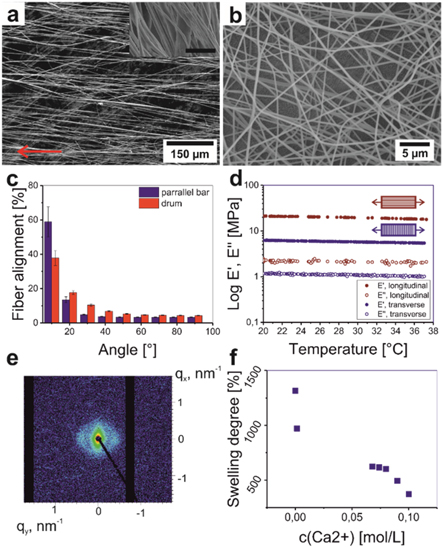
Figure 2. Properties of individual PCL and AA-MA electrospun mats: representative scanning electron microscopy (SEM) images of PCL ((a), arrow indicates the preferred fiber direction, which is also visible in the inset) (scale bar in the inset 5 μm) and AA-MA (b) fibers collected on parallel bars collector; fiber alignment depending on collector used for electrospinning (c); dynamical mechanical analysis (DMA) results of PCL mats (d); small-angle x-ray scattering (SAXS) image of PCL mat collected on parallel bars (e); swelling degree of AA-MA in different Ca2+ concentrations (f).
Download figure:
Standard image High-resolution imageIt was determined that the parallel bars collector resulted in a higher degree of alignment of PCL fibers (60% of all fibers had <10° fiber orientation angle) compared to the drum collector (40%). On the other hand, the rotating drum allowed fabrication of a thicker fiber mat (500 μm) in comparison wiht the parallel bar (100 μm) (figure 2(c)). We observed that the degree of fiber alignment in mats produced by both methods decreased with increasing spinning time and the thickness of mat, which was caused by fiber thickening and entanglement [39]. Small and wide angle x-ray scattering measurements confirmed uniaxial orientation of polymer chains and lamellas. At low scattering vectors q the SAXS signal scales with q−4 as expected for a 3D object as the mat. The strong anisotropy of the signal in that range proves the preferred orientation of the fibres inside the mat. A shoulder around 0.05 Å−1 is visible in the 1D data, corresponding to a correlation length of about 14 nm, if the mat is measured in parallel beam direction this feature is seen in the 2D image as spots on opposite sites. As a result of the preparation method, the peakedness of the shoulder is most pronounced in parallel geometry as a consequence of the better orientation in the equatorial plane (thinnest dimension) of the mat. The preferred orientation of the fibres itself is reflected by the lozenge-like shape at lowest q. The degree of crystallinity of electrospun PCL fibers was of about 40% as it was revealed by Differential Scanning Calorimetry (DSC) (figure S2(a)).
Dynamic mechanical analysis (DMA) revealed the anisotropic mechanical properties of PCL mats—there is a significant difference of elastic modulus in different directions (figure 2(d)). Elastic modulus measured for longitudinal orientation of fibers was 20.7 MPa and it was significantly higher than that measured for transverse orientation (E = 6.3 MPa). The higher value of longitudinal modulus can be explained by the fact that the stretching of the oriented fiber requires larger force than the separation of individual fibers. We separately investigated swelling properties of freestanding AA-MA mat. It results that the swelling degree of polymer mat decreases with increasing concentration of Ca2+ ions (figure 2(f)). Interestingly, while the thickness of photocrosslinked AA-MA mats strongly depends on concentration of Ca2+ ions (range 300%–1300%) (figure 2(f)), the lateral width changes are almost independent of concentration of Ca2+ ions and are in the range 10%–15% (figure S2(d)).
The PCL-alginate bilayers demonstrated shape-transformation behavior in an aqueous environment (water, PBS, water with different Ca2+ ion concentration) as they started to roll and form tubular scroll-like structures. Eventually, the diameter of these tubes and the direction of folding of bilayers depend on both: (i) the orientation of PCL fibers with respect to the main axis of a polymer mat, and (ii) the concentration of Ca2+ ions (figure 3). We observed that bilayers roll and form tubes in an aqueous environment with low Ca2+ ions concentration. PCL and AA-MA mats formed the inner and outer surfaces of the tubes, respectively (figure 3(a)). Increased concentration of Ca2+ ions resulted in unrolling of the bilayers due to the decreased swelling degree of alginate in different concentrations of Ca2+ ions solution (0.00145–0.08 mol l−1, figure 3(b)). Interestingly, we observed a change of direction of folding of bilayer towards AA-MA side at a certain Ca2+ ions concentration (∼0.08 mol l−1 for samples with PCL/AA-MA thickness ratio 0.5–6). In this case, the bilayers flexed such that the PCL layer was under tension, or, in other words, there was convex flexure of the PCL side (figures 3(c)–(e)). The mechanism behind this bending is likely the relaxation of stretched PCL fibers [18]; during electrospinning the PCL fibers are stretched and therefore they relax and slightly bend towards the AA-MA side as soon as they are removed from the collectors (dry state). Likewise, after the addition of Ca2+ ions solution (wet state) the relaxation behavior of PCL fibers restrict the swelling of AA-MA fibers and bend the bilayer towards the alginate side.
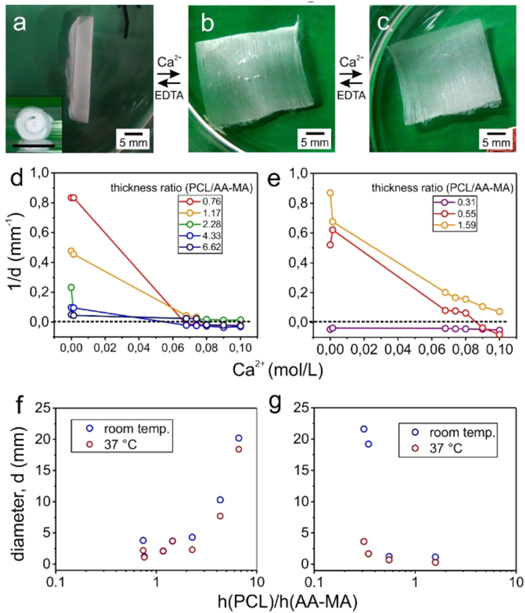
Figure 3. Folding behavior of PCL/AA-MA electrospun bilayer mats: folded tube in water (insert: tube side view) (a); slightly folded sample to PCL side in aqueous solution with 0.05 mol l−1 Ca2+ ion concentration (b); sample folded to alginate side in water with 0.1 mol l−1 Ca2+ ion concentration (c); dependency of structural properties of PCL/AA-MA mats on each layer thickness, their ratio and Ca2+ ion concentration for rotating drum (d) and parallel bars (e); electrospun bilayer tube diameter dependency on each layer thickness (h(PCL) and h(AA-MA)) and temperature for rotating drum (f) and parallel bars (g).
Download figure:
Standard image High-resolution imageThe ratio between thickness of PCL and AA-MA mats as well as the temperature of aqueous environment also affects the tube diameter. As it is shown in figures 3(d)–(e), increase of the thickness of PCL mat first resulted in decrease of tube diameter. Symmetric bilayer mats (1:1 thickness ratio of PCL and AA-MA, h(PCL)/h(AA-MA)) form tubes with minimal diameters. Further, an increase of the thickness of PCL mat resulted in the increase of the diameter of the tubes (figures 3(d)–(e)). Qualitatively, this behavior can be explained by considering intrinsic properties of the materials. In a thin PCL mat (ratio PCL/AA-MA < 0.3), PCL layer is not stiff enough to resist against the swelling of alginate layers, therefore, the tube diameter is large. Thicker PCL layer (0.3 < ratio PCL/AA-MA < 2 ) is able to sufficiently restrict the swelling of AA-MA mat to reduce the diameter of the resulted tube. However, a very thick layer of PCL (ratio PCL/AA-MA > 2), in opposition, showed stiffer behavior and a swollen layer of AA-MA was not able to deform or bend the bilayer. Further, temperature was shown to have an effect on the tube diameter: generally, the diameter of tubes formed at higher temperature (37 °C) was slightly smaller than those formed at room temperature (figures 3(f)–(g)) due to the softening and relaxation of PCL at higher temperatures [18]. Therefore, the variation caused by temperature changes on tube diameters is more profound when the AA-MA layer is thicker than the PCL layer. Consequently, we can conclude that PCL/AA-MA bilayer electrospun mats are able to form tubes in an aqueous environment and the diameter of these tubes can be precisely controlled by varying the thickness of the layers, the concentration of Ca2+ ions and the temperature.
The folding scenario of bilayer mats depends also on their shape and total thickness (figures S3–5). In terms of shapes, we examined rectangular, square and circular mats, and in terms of thickness we measured thin (thickness ≤100 μm) and thick (thickness ≥500 μm) mats. Thin rectangular bilayer mats (≤100 μm) were always rolled perpendicular with respect to the orientation direction of fibers (figures S4(a)–(d)). Square mats also fold crosswise with respect to direction orientation of fibers (figures S4(e)–(f)). Their folding starts from two opposite sides and results in fibers being perpendicular to the main axis of the formed tube (figure S3). Interestingly, the circular mat started to fold predominately from one side and the folding was always parallel with respect to the main axis of orientation and the direction of fibers. In other words, the resulted tubes had fibers oriented along the main axis of the tube (figures S4(g)–(h)).
Folding of thicker samples (≥500 μm) also depends on their shape and thickness (figure S5). Similar to the folding scenario of thin circular mats, thick circular mats form tubes by having PCL fibers oriented along its length (figure S5(c)). Rectangular mats folded predominantly such that fibers in the formed tube are oriented along the axis of the tube (figures S5(b), (d)). In case of square shaped mats, the folding began at opposite corners of the mat, which resulted in a small-angle twisting in respect to the length of the tube (figure S5(a)). One can assume that there are four factors that can effect a scenario of folding of rectangular and square bilayers: (i) mechanical anisotropy determined by orientation of PCL fibers, (ii) shape/edge effects, (iii) thickness and (iv) environmental conditions (temperature, ion concentration). Due to the full symmetrical shape, folding of circular mats shall not be influenced by shape/edge effects, therefore, the circular shape is most promising for the fabrication of tubes with parallel orientation of fibers.
To study the formation of muscle microtissue on electrospun mats, we used thin (<100 μm) PCL/AA-MA bilayer mats prepared using parallel bars cut into the shape of circles and seeded with mouse myoblasts (C2C12) on the PCL side of the bilayer (oriented fibers). This system was used due to 20% higher alignment of PCL fibers, and a smaller formed tube diameter which is closer to natural muscle fiber diameter (100 μm) [40]. The cell adhesion to hydrophobic PCL layer was improved by its treatment with fibronectin, collagen, and albumin (FNC) solution. Previously, we showed the effect of FNC protein coating to improve the adhesion of cells on the surface of hydrophobic materials such as PCL [31]. Non-coated bilayer and PCL mats were used as controls. During experiments, we have observed no cell adhesion on the alginate side of the bilayer which can also clearly show that PCL fibers are the side for adhering and aligning the cells. As mentioned above, our porous PCL/AA-MA bilayer mats form tubes due to the swelling of alginate material and self-folding behavior. Therefore, to control the cell seeding and to facilitate the imaging process for future steps, samples were fixed in cell culture crowns to avoid instant tube formation. However, as a result of self-folding, cultured cells were able to be trapped inside the non-transparent 3D structure and formed a cell layer within the construct without any disruption of self-folded structure, as is shown in the electrical stimulation section (figure 6(c)).
Cells cultured on bilayers as well as PCL aligned fiber mats showed a high viability above 90% independently, whether mats were treated with FNC or not. As it was shown in (figure S6–9), myoblast cells on non-coated (aligned) PCL fibers, did not adhere with homogenous distribution and rather formed clusters. Moreover, after 7 days of culture those clusters did not show alignment on fibers and stayed with a round morphology. However, on FNC coated fibers, cells were able to adhere and spread (figure S13). Therefore, bilayers were treated with FNC in all further experiments to promote cell adhesion.
In addition, we observed that thickness of AA-MA and PCL layers affected the cell growth and viability. On the bilayer mats with 20 μm thick PCL and 60 μm thick AA-MA, cells tended to make a cluster and spread weakly (figure S10). In fact, on such a bilayer with thicker AA-MA layer and thinner PCL layers, more cells are in contact with swollen AA-MA fibers, which do not offer any chemical groups to adhere to (figures S7 and 11).
Cell alignment on fibrous mats, which was analyzed after staining of actin filament and nuclei, using DAPI and phalloidin, also confirmed the dependency of cells behavior on thickness of alginate layer and surface treatment with FNC. As mentioned above, the presence of an AA-MA layer in the bilayer mat resulted in the lower degree of cell alignment one day after the cell seeding independently, whether it was coated with FNC or not. However, this poor alignment was significantly improved after a week of culture (figures 4, S11–14). Accordingly, we cultured the cells on PCL control samples (coated and non-coated) and observed the treatment of PCL mats with FNC allowed substantial increase of degree of cell alignment even one day after culture. After seven days, all samples showed comparable cell alignment ∼30% of the cells were aligned with the fibers. This was also confirmed by SEM micrographs, where we could see the formation of monolayer of muscle cells on bilayer after seven days of culture (figure S15). As it was mentioned, lower initial cell alignment on bilayer mats and weak cell adhesion on thin bilayers can be explained by the influence of alginate. In fact, alginate is a polysaccharide that does not contain any chemical groups promoting cell adhesion. FNC most probably was not adsorbed by this hydrophilic hydrogel but provided a thin protein coating to cells for the initial cell attachment.
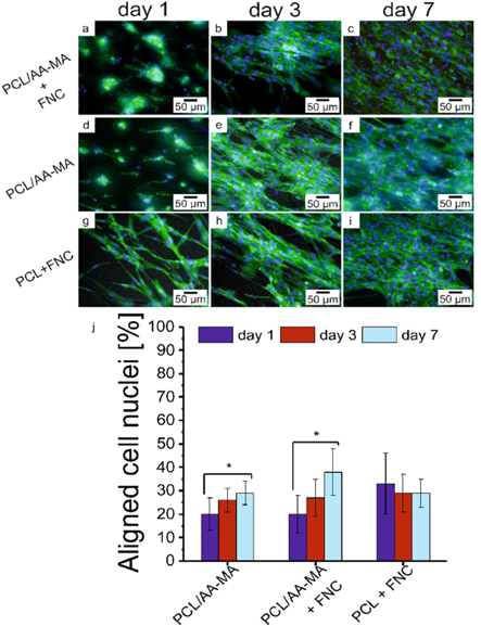
Figure 4. Actin filament and nuclei staining using DAPI (blue) and Phalloidin (green) to evaluate the cell alignment on bilayer and PCL mats: fluorescence images of cells on bilayer, bilayer coated with FNC and PCL coated with FNC mats after 1, 3 and 7 days of culture (a)–(i); quantification analysis of cells nuclei alignment on fibrous scaffolds (j) (*, p < 0.05 compared to other samples).
Download figure:
Standard image High-resolution imageAfter 7 days of culture, the medium was exchanged with one containing a lower serum content (2% horse serum) to enhance the differentiation and fusion of myoblasts cells to myotubes. To prove the formation of muscle tissue bundles, the myogenesis was monitored using immunostaining and quantified within one week of differentiation on the fibrous mats. We observed generation of small myotubes and fusion of myoblasts after 4 days of differentiation (150 μm length and number of nuclei lower than 5) (figures 5(h), (i), S16–18). They continued to enlarge and mature within 7 days up to 350 μm length and number of nuclei higher than 8 on FNC-coated PCL/AA-MA bilayer mat. In the first 4 days of differentiation, we observed faster myotube formation on PCL mats compared to bilayers, and cells grew in width rather than length, resulting in a slight decrease of their aspect ratio. Myotube formation was likely delayed by alginate, which does not promote cell adhesion. We observed the formation of continuous layer of muscle fibers on the surface of bilayer and PCL mats after 7 days of differentiation.
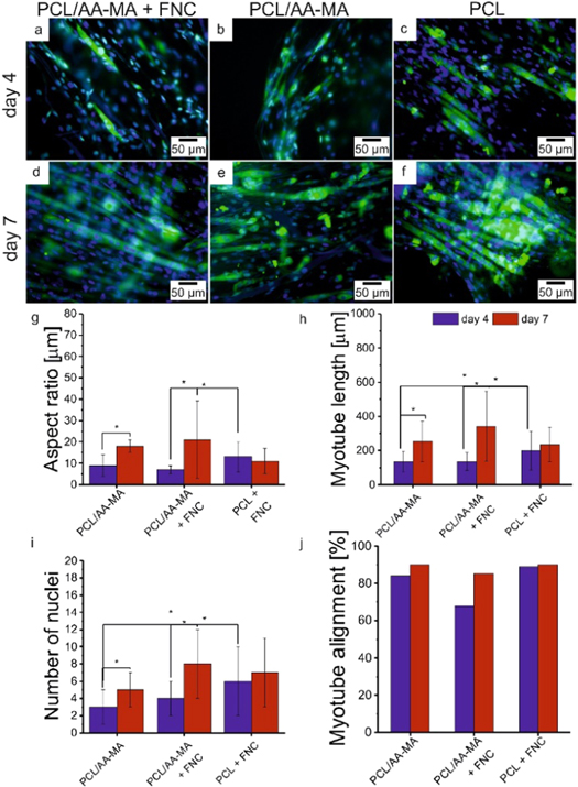
Figure 5. Immunostaining images (myosin heavy chain (green) and nuclei (blue) staining) taken by fluorescent microscope showing myogenesis in C2C12 muscle cells (a)–(f); Myogenesis quantification (g)–(j): aspect ratio (g); length (h); number of nuclei (i); alignment (j); of myotubes after 4 and 7 days of differentiation on bilayer coated with FNC, bilayer and PCL coated with FNC.
Download figure:
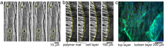
Standard image High-resolution imageThe functionality and contractility of the muscle cell layer formed on the fibrous self-folding bilayer was tested after 7 days of differentiation by electrical stimulation (14 days total in culture). We observed that the mature myotubes, which are oriented along fibers contract synchronously with the applied pulses (figure 6, video S19–21). Moreover, we observed that a continuous muscle fiber layer, which was delaminated from a bilayer mat upon its manual unfolding, contracts as whole under electrical stimulation. This implied that there was a formation of functional, aligned skeletal muscle microtissue (thickness ∼20 μm) inside the self-rolled fibrous PCL/AA-MA bilayer mat.
Figure 6. Contractility of the muscle fibers layer under electrical stimulation (4–5 V, frequency: 1 Hz, duration: 1 ms): functional contracting myotubes that are observed by cyclical displacement of features inside yellow circles (a); contracting cell monolayer, solid and yellow dashed lines show edge of contracted and relaxed myotubes layer, respectively (b). Time between images is 1 s; 3D projection of myoblast muscle cells on self-folded bilayer (c). Actin filament and nuclei staining using DAPI (blue) and Phalloidin (green) to evaluate the cell alignment on bilayer mats.
Download figure:
Standard image High-resolution image
4. Conclusions
Using a 4D biofabrication approach, we were able to produce functional skeletal muscle microtissues. PCL/AA-MA electrospun bilayer mats with uniaxial alignment of PCL fibers were able to undergo programmed shape-transformation and to form multilayer scroll-like tubular constructs, where the fibers were aligned in parallel with the tube's axis. These longitudinally aligned fibers were able to guide the alignment of myoblasts and to allow the fabrication of a continuous structure of aligned myotubes inside the self-rolled multilayer construct, which are able to contract responding to electrical stimulation.
This new approach allows fabrication of important building blocks for tissue engineering—aligned 3D skeletal muscle fiber bundles with tubular structure. This hollow tubular construct can be further developed for formation of vascularized tissue to deliver oxygen and nutrition to the cells inside the rolled construct, eventually maturing into a piece of tissue to be implanted into the body.
Acknowledgments
This work was supported by DFG (Grant N. IO 68/11-1; IO 68/14-1; SA 3575/1-1; Project N 326998133—SFB/TRR225 (subproject B03)). We would further like to thank Prof. Minko and Prof. Scheibel for providing us with electrospinning equipment and lab facilities, and Elise DeSimone for paper revisions.