
Abstract
In this study, a fibrous nanocomposite scaffold was developed by combining hydroxyapatite (HA) fibers produced by electrospinning method and arginine–glycine–aspartic acid (RGD)-bearing peptide-amphiphile (PA) gel (PA-RGD) produced by self-assembly and gelation induced by calcium ions. Scanning electron microscope, transmission electron microscope and atomic force microscopy imaging confirmed the successful production of inorganic and organic components of this nanocomposite material. Within the HA, the presence of a CaCO3 phase, improving biodegradation, was shown by x-ray diffraction analysis. The in vitro effectiveness of the PA-RGD/HA scaffold was determined on MC3T3-E1 preosteoblast cultures in comparison with HA matrix and PA-RGD gel. The highest cellular proliferation was obtained on PA-RGD gel, however, alkaline phosphatase activity results denoted that osteogenic differentiation of the cells is more favorable on HA containing matrices with respect to PA-RGD itself. Microscopic observations revealed that all three matrices support cell attachment and proliferation. Moreover, cells form bridges between the HA and PA-RGD components of the nanocomposite scaffold, indicating the integrity of the biphasic components. According to the real time-polymerase chain reaction (RT-PCR) analyses, MC3T3-E1 cells expressed significantly higher osteocalcin on all matrices. Bone sialoprotein (BSP) expression level is ten-fold higher on PA-RGD/HA nanocomposite scaffolds than that of HA and PA-RGD scaffolds and the elevated expression of BSP on PA-RGD/HA nanocomposite scaffolds suggested higher mineralized matrix on this novel scaffold. Based on the results obtained in this study, the combination of HA nanofibers and PA-RGD gel takes advantage of good structural integrity during the cell culture, besides the osteoinductive and osteoconductive properties of the nanofibrous scaffold.
Export citation and abstract BibTeX RIS
1. Introduction
Bone tissue engineering requires the uses of engineered biomaterials, in other words scaffolds, that fully mimic a bone extracellular matrix (ECM) to regenerate bone defects due to trauma, infections, surgical operations or accidents. Bone ECM is mainly composed of a nanofibrillar three dimensional (3D) protein network of collagen and inorganic hydroxyapatite (HA, Ca10(PO4)6(OH)2) nanoparticles distributed along collagen fibers. Collagen fibers are in the size range of 50–500 nm and serve as a physical support for cells. Bone HA nanoparticles have a semicrystalline structure almost 50 nm in size, they are osteoconductive and are a good source of calcium and phosphate ions necessary for the survival of the cells [1].
Since cells are surrounded by a highly hydrated porous network, hydrogels remain the most attractive scaffolding material due to their structural similarity to the native ECM. A number of hydrogels composed of synthetic and natural polymers [2] or their composites, including calcium phosphates [3], have been developed as effective bone scaffolds. Furthermore, scaffolds with a nanofibrous morphology were shown to better recreate a bone microenvironment in terms of porosity, topography and chemistry [4, 5]. Strategies for fabrication of nanofibrous scaffolds includes electrospinning, phase separation, template synthesis and self-assembly [6]. Recently, peptide-amphiphile (PA) molecules which are self-assembling into nanofibers were designed and produced for tissue engineering applications [7]. These molecules include several domains consisting of; hydrophobic alkyl chains inducing a driving force to form nanofibers via hydrophobic interactions, an amino acid sequence covalently linked to the alkyl chain that forces self-assembly of the molecules through the formation of β-sheet, charged amino acids which make the molecule soluble in an aqueous environment and a bioactive epitope that can interact with cellular receptors, biomolecules or ligands. Self-assembly and gelation of the PA molecules can be triggered by the addition of monovalent or polyvalent metal ions such as K+, Mg2+, Ba2+, Cu2+ and Ca2+ into the aqueous peptide solution by screening the charged amino acid sequences of a design molecule [8]. A number of PA-based hydrogel scaffolds were produced by the addition of Ca2+ for various tissue engineering applications. However, a lack of mechanical integrity is one of the major drawbacks of such scaffolds [9, 10].
Solid phase peptide synthesis was employed for PA production using Fmoc chemistry and this method allows flexibility to incorporate specific amino acid sequences into molecular chains of PAs derived from several bioligands or growth factors. Recent efforts have been focused on adapting short peptide sequences of ECM molecules mostly the arginine–glycine–aspartic acid (RGD) sequence, to the PA molecules. RGD sequence was adapted into the PA molecule containing phosphoserine residues and these nanofibers were able to direct mineralization of HA which is the same as observed between collagen fibrils and HA crystals in bone [11]. Hosseinkhani et al produced 3D PA scaffolds including the RGD sequence and this structure significantly enhanced the osteogenic differentiation of mesenchymal stem cells [12]. After all, RGD was found to be the most osteoinductive peptide sequence based on the evidence obtained from these studies.
On the other hand, osteoconductivity and bone-bonding ability could be achieved by using bioceramics, mainly HA and β-tricalcium phosphate (β-TCP). Although β-TCP materials have the advantage of faster resorption rates, HA would be more effective for long term applications with acting as a reservoir of calcium and phosphate ions [13]. Moreover, HA scaffolds composed of nanocrystalline particles have higher degradation rates which facilitate the bone remodeling process [14]. A number of HA production methods, such as wet precipitation, solid state reactions, hydrothermal synthesis and the sol–gel method have been reported [15]. More recently, combining the sol–gel method with the electrospinning process has led to the fabrication of highly porous 3D HA nanofibers in order to chemically and morphologically mimic the ECM of bone [16]. Dai et al used polyvinyl alcohol as a polymer carrier and triethyl phosphite and calcium nitrate as sol–gel precursors in successive studies [17, 18]. In addition, nonwoven, tubular and aligned nanofibrous structures were produced by using HA nanorods/polyvinylpyrrolidone (PVP) after subsequent calcination and mesenchymal stem cells were successfully attached and spread on these HA fabrics [19].
The aim of the current study was to fabricate a nanocomposite scaffold composed of RGD-bearing peptide amphiphile (PA-RGD) and hydoxyapatite nanofibers and to investigate its effectiveness for bone tissue regeneration. To the best of our knowledge, HA matrices in nanofibrous form have not been combined with the PA hydrogels in the literature yet. It was assumed that the nanocomposite scaffold would provide osteoinductivity by the availability of RGD bioligand in PA and thereby, the HA nanofibrous matrix embedded hydrogel resulted in an osteoconductive environment with desired mechanical integrity. For this purpose, PA-RGD was produced by solid phase peptide synthesis using Fmoc chemistry and Ca2+ was used as a gelling agent. For inorganic components, HA/PVP nanofibrous matrices were produced by the combination of sol–gel chemistry and the electrospinning process. HA nanofibrous matrices were then obtained after subsequent calcination at elevated temperatures. These nanostructured materials were characterized separately by suitable chemical and morphological testing methods. Osteogenic potential of this nanocomposite scaffold was investigated using a MC3T3-E1 preosteoblastic cell line.
2. Materials and methods
2.1. Materials
Calcium nitrate tetrahydrate and phosphate buffered saline (PBS) tablets were purchased from Sigma-Aldrich (USA). Triethyl phosphite, calcium chloride (CaCl2) and sodium hydroxide (NaOH) were obtained from Merck (Germany). PVP (Kollidon® 90 F, Mw ≈ 1150 000 g mol–1) was obtained from BASF Chemicals (Germany). Ethanol (96% v/v) was purchased from Merko Chemicals (Turkey). All the chemicals were used as received.
For cell culture studies, Minimum Essential Medium Alpha Modification (α-MEM) was obtained from Lonza (USA). Fetal bovine serum (FBS) was purchased from Biological Industries (Israel). Trypsin/EDTA solution, glutaraldehyde (25% v/v), hexamethyldisilazane, β-glycerolphosphate, ascorbic acid, 3-[4,5-dimethylthiazol-2-yl]-diphenyltetrazolium bromide (MTT), hydrochloric acid (HCl), isopropanol, Triton X-100, propidium iodide, p-nitrophenyl phosphate liquid substrate system (p-NPP) and silver nitrate (AgNO3) were obtained from Sigma-Aldrich (USA). Magnesium chloride (MgCl2) was purchased from Merck (Germany) and Alexa Fluor® 488 Phalloidin was obtained from Invitrogen (USA). All the water used in cell culture experiments was ultrapure water which is obtained from Barnsted EasyPURE™ system (Thermo Scientific, USA).
2.2. Sol–gel synthesis of hydroxyapatite nanoparticles
HA nanoparticles were synthesized by the sol–gel method as described in literature [20]. Calcium nitrate tetrahydrate and triethyl phosphite were used as calcium and phosphorus precursors for preparing the HA sol, respectively. In brief, 1.31 mL of triethyl phosphite was hydrolyzed with 2.50 mL of distilled water for 24 h in a sealed Erlenmayer flask under continuous stirring. A stoichiometric amount (Ca/P molar ratio of 1.67) of calcium nitrate tetrahydrate (2.98 g) was dissolved in 2.50 mL of distilled water in a separate flask and then this solution was added dropwise into the hydrolyzed phosphite sol. The obtained mixture was stirred vigorously for 10 min and aged statically at 45 °C for 2 h. Then, it was dried at 80 °C until a white gel was obtained. The dried gel was further calcinated at 600 °C for 12 h by heating from room temperature with a 5 °C min−1 heating rate for subsequent characterization studies.
2.3. Production of HA nanofibrous matrices
The HA sol–gel solution was mixed with 10% PVP solution dissolved in ethanol with a weight ratio of 1:3. This mixture was then continuously stirred at 45 °C for 2 h and used for the electrospinning process. A solution of 10% PVP in ethanol without HA sol was also used for electrospinning under the same conditions for comparison purposes. HA/PVP solution was then loaded into the 5 mL plastic syringe fitted with a blunt-ended needle with an inner diameter of 0.4 mm. The needle was placed at a distance of 10 cm from the grounded collector and the solution feed rate was fixed at 0.5 mL h–1 using a syringe pump (New Era Pump Systems Inc., USA). The 12 kV voltage was applied using a high voltage power source (Gamma High-Voltage Research, FL, USA). The composite nanofibrous matrices were collected on non-stick aluminum foil (Reynolds Wrap, USA) in the nonwoven form and then dried in a vacuum oven for 24 h. Square samples of 15 mm × 15 mm were cut with a scalpel and HA nanofibrous matrices were obtained after calcination at 600 °C for at least 12 h by heating from room temperature with a heating rate of 5 °C min−1.
2.4. Preparation of peptide-amphiphile nanofibrous matrices
2.4.1. Peptide-amphiphile synthesis
PA was synthesized using Fmoc chemistry by Genecust (Dudalange, LU). In this study, PA consists of RGD (arginine–glycine–aspartic acid, a bioactive epitope), a glutamic acid (E), three glycine (G) residues, four alanine (A) residues, followed by an hydrophobic alkyl tail of palmitoyl. Successful PA synthesis and purity was verified by mass spectrometry and high performance liquid chromatography (HPLC).
2.4.2. Self-assembly and gelation of peptide-amphiphile gels
PA-RGD was dissolved in deionized water (DI) with a weight ratio of 1% and was used as a stock solution. The pH of this solution was then adjusted to 7.0 by the addition of 100 mM NaOH. Self-assembly and gelling were induced by the addition of 10 µL of 0.2 M CaCl2 solution to 50 µL of PA-RGD solution in 24-well cell culture dishes attached to the glass coverslips.
2.5. Formation of PA-RGD/HA nanocomposite scaffolds
In order to prepare PA-RGD/HA nanocomposite scaffolds, the gelation process of PA was carried out in the presence of a HA matrix (5 mm × 5 mm). This nanocomposite structure was then incubated in an oven at 37 °C for at least 2 h to obtain a stable gel structure containing HA nanofibers.
2.6. Characterization studies
2.6.1. X-ray diffraction (XRD) analysis
Phase identification and purity of HA nanoparticles, the HA/PVP composite and HA nanofibrous matrices was investigated by an x-ray diffractometer (PANalytical X'Pert Pro MPD, Holland) at a scanning speed of 0.067 °s–1, from 20° to 80°. While HA nanoparticles were analyzing in powder form, HA/PVP and HA nanofibrous matrices were analyzed in membrane form.
The crystal size of the HA nanoparticles and HA nanofibrous matrices were estimated based on the XRD pattern according to the Scherrer equation (1) [21]:

where λ is the wavelength of CuKα as 0.15418 nm, B is the peak-width at half maximum intensity of HA(2 1 1) in radians and θ is the angle of the 2 1 1 peak in degrees.
The degree of crystallinity of the HA nanoparticles and HA nanofibrous matrices was calculated by equation (2) [22]:

where V1 1 2/3 0 0 is the intensity of the valley between the peaks of (1 1 2) and (3 0 0) planes for HA and I300 is the intensity of the peak from the (3 0 0) plane.
2.6.2. Attenuated total reflection infrared spectroscopy (ATR-FTIR) analysis
Chemical structures of the HA nanoparticles, HA/PVP composite and HA nanofibrous matrices were examined with ATR-FTIR analysis by using a Nicolet iS10 FTIR spectrophotometer (Thermo Scientific, MA, USA) in the range of 400–4000 cm−1. All the spectra were collected at a resolution of 4 cm−1 with 64 scans for each sample.
PA-RGD gel was prepared as described in section 2.4.2. This gel was then frozen and freeze-dried. Chemical and conformational analysis for PA-RGD gels were also studied with a FTIR spectrophotometer.
2.6.3. Thermogravimetric analysis (TGA)
Thermal characteristics of HA nanoparticles, the HA/PVP composite and HA nanofibrous matrices were investigated using EXSTAR 6000 TG/DTA 6300 (SII NanoTechnology Inc., Japan). Samples were heated from 25 to 800 °C with a heating rate of 10 °C min−1 under flowing air. Weight losses and thermal properties were investigated from the obtained thermograms.
2.6.4. Porosity measurements
The thickness of the HA nanofibrous matrix was measured by means of a micrometer. Then its apparent density and porosity was estimated through equations (3) and (4), respectively;

where theoretical density of HA, 3.156 g cm−3, was taken as bulk density.
2.6.5. Scanning electron microscope (SEM) analysis
The morphology of the HA/PVP composite, HA nanofibrous matrices and the fibrous networks formed by the PA-RGD molecules were visualized by SEM (Zeiss Evo 50, Germany). The PA-RGD gel was prepared as described previously and fixed with 2.5% (v/v) glutaraldehyde in PBS for 30 min. The fixed sample was rinsed in 0.01 M PBS for 5 min and then dehydrated in an ethanol series (i.e., 30, 50, 70, 90 and 100%, respectively). After dehydration, the gel was rinsed with hexamethyldisilazane for 5 min and air dried. The dried gel, HA/PVP composite and HA nanofibrous matrices were mounted on stubs and coated with a thin layer of gold before SEM analysis. Fiber diameters and size distributions were measured from SEM images using ImageJ software (National Institute of Health, MD, USA).
2.6.6. Transmission electron microscope (TEM) analysis
The size, morphology and crystal structure of the HA nanoparticles and HA nanofibrous matrices were investigated by using a TEM (FEI Tecnai Spirit G2 BioTwin, Holland). HA nanoparticles and HA nanofibrous matrices were dispersed in ethanol and homogenized three times for 30 s using an ultrasonic homogenizer (Bandelin Sonopuls HD2070, Germany). Then, a drop of each solution was placed on a carbon film coated copper grids (300 mesh) and they were dried in air.
PA-RGD gel structure was formed on a copper grid for TEM analysis. Ten µL of 2 mM PA-RGD solution at pH 7 was dropped on a grid and mixed with 2 µL of 250 mM CaCl2 solution. Excess water was then removed with tissue paper and the sample was stained with 2% wt aqueous uranyl acetate solution for 5 min. Excess water was again removed with tissue paper and the sample was air-dried overnight. TEM analysis was done at an accelerating voltage of 80 kV.
2.6.7. Atomic force microscopy (AFM) analysis
The AFM sample was prepared on a round glass coverslip (1.2 mm diameter) with a 0.5 mM PA-RGD solution as follows. 100 µL of PA-RGD solution at pH 7 was placed in an Eppendorf tube and thereafter, 3 µL of 50 mM CaCl2 solution was added. The tube was vortexed, sonicated for 5 min and casted on a coverslip. Excess water was removed with tissue paper and the sample was air-dried overnight. Topography of the PA-RGD gel was examined by Veeco Multimode V AFM in tapping mode with a phosphorus doped silicon tip.
2.6.8. Circular dichroism (CD) analysis
CD spectra of PA-RGD solutions were taken by using a spectropolarimeter (J-815, Jasco, Japan). PA-RGD (0.1 M) solutions were prepared in DI and the pH was then adjusted to 7.0 by the addition of 100 mM NaOH. Then, 0.5 mL of PA-RGD solution was added to the Eppendorf tubes and mixed with 5 µL of 50 mM CaCl2. The mixture was incubated for 2 h in order to obtain complete self-assembly. PA-RGDs with or without CaCl2 were measured in the far UV region of 190 to 300 nm using quartz cuvettes with 1 mm path length at room temperature.
2.7. Cell culture studies
The preosteoblastic MC3T3-E1 cells obtained from Riken Cell Bank (Japan) were used for cell culture studies. These cells are anchorage-dependent, grown in monolayer cultures and derived from mouse calvarium tissue. They were subcultured in culture flasks (Nunc™, Germany) using α-MEM supplemented with 10% (v/v) FBS and 1% (v/v) antibiotic solution (penicillin–streptomycin, Sigma-Aldrich, USA). The cells were incubated at 37 °C in a humidified CO2 atmosphere (Heraus Instruments, Germany). All the cell culture studies were performed in a Laminar Flow Cabinet (Bioair, Type II Laminar Flow Cabinet, Italy).
2.7.1. Cell seeding
The solution of 1% wt PA-RGD was prepared in ultrapure water and pH of the solution was adjusted to 7.0 by the addition of 100 mM NaOH. This solution was then filtered through a 0.22 µm filter (Millipore, USA) and sterilized under UV light for 2 h. At the same time, HA nanofibrous matrices were also sterilized under UV for 2 h. MC3T3-E1 cells were trypsinized from the flasks and suspended at a density of 5 × 10⁵ cells mL−1 in the osteogenic medium (α-MEM plus 10 mM β-glycerolphosphate and 50 µg mL−1ascorbic acid) supplemented with CaCl2 to obtain a final Ca2+ concentration of 0.2 M. 50 µL of PA-RGD solution was poured onto the 12 mm glass coverslip in a 24-well culture plate, self-assembly and gelation were induced by the addition of 10 µL of cell suspension (5000 cells per scaffold) including CaCl2. The solution was gently mixed with a pipette tip. Following gelation, HA nanofibrous matrices were immediately placed into the PA-RGD gels and the obtained structures were incubated at 37 °C in a CO2 oven for 2 h to obtain stable PA-RGD/HA nanocomposite scaffolds. Then, 300 µL of culture medium was added to the each well, completely covering the scaffolds. Half of the medium was exchanged every two days during the cell culture period. Cells were also seeded on PA-RGD and HA scaffolds for comparison.
2.7.2. Cell proliferation analysis by MTT assay
Cell proliferation was assessed by the MTT test which is based on the mitochondrial activity of the live cells. At each selected time, culture medium was aspirated and 600 µL of prewarmed culture medium (α-MEM) supplemented with 60 µL MTT solution (2.5 mg mL−1 MTT dissolved in PBS) was added to each sample, which were incubated at 37 °C for 3 h. After the incubation period, the medium was removed from each well and 400 µL of 0.04 M HCl in isopropanol solution was added into each well to dissolve formazan crystals. 200 µL of result solution in crystal violet color was used for measuring optical density spectrophotometrically at 570 nm with reference to 690 nm using a microplate reader (Asys UVM 340, Austria).
2.7.3. Microscopic imaging
The morphology of the cells in the scaffolds were observed by SEM (Zeiss EVO 50, Germany) on the seventh day of culture. The cell culture medium was removed and the scaffolds were washed with PBS twice. Then, the cells were fixed with 2.5% (v/v) glutaraldehyde in 0.1 M Dulbecco's PBS for 30 min. The scaffolds were dehydrated in a grading ethanol series (30, 50, 70, 90 and 100%) and then, dried with HMDS in air. The samples were coated with a gold layer prior to SEM analysis.
Cytoskeleton organization and cellular morphology within scaffolds was visualized at 7 and 14 days after cell seeding by fluorescence microscopy (Olympus IX71, Japan), respectively. Firstly, culture media were removed from each well and the scaffolds were transferred to a new 24-well plate. Then, scaffolds were washed with PBS (pH = 7.4) three times at room temperature and samples were fixed with 2.5% (v/v) glutaraldehyde in 0.1 M PBS for 10 min at 4 °C. After fixation, the scaffolds were again washed with PBS three times and fixed cells were permeabilized with 0.1% Triton X-100 solution for 5 min. Cell cytoskeletal filamentous actin (F-actin) was visualized by treating the cells with 2.5% (v/v) Alexa Fluor 488 phalloidin (Invitrogen Inc., USA) for 20 min in darkness. For this purpose, Alexa Fluor 488 phalloidin was first dissolved in 1.5 mL of methanol to yield a final concentration of 6.6 µM and this solution was used as a stock. 200 µL was taken from the stock solution and then, it was completed to 8 mL with a 1% bovine serum albumin (BSA)/PBS buffer to give a final concentration of 0.165 µM. Nuclei were stained with 10 µg mL−1 propidium iodide for 5 min.
2.7.4. Alkaline phosphatase (ALP) activity
ALP activities of the cells were evaluated on the 7th and 14th days of culture. At the end of each culture period, scaffolds were rinsed twice in PBS and stored at −80 °C. After freeze-drying, samples were cut down with a scissors and homogenized by brief sonication at 0 °C in the lysis buffer (1% Triton X-100). Cell lysates were centrifuged at 12 000 rpm for 10 min at 4 °C. The supernatant was assayed for ALP activity, using p-NPP as substrate. About 50 µL of lysate was added to 125 µL ALP solution (56 mM 2-amino 2-methyl-1,3-propanediol, pH = 9.8 and 1 mM MgCl2 containing 10 mL p-NPP), and the mixture was incubated at 37 °C for 30 min. The reaction was stopped by adding 50 µL of 2.5 M sodium hydroxide, and ALP activity was determined by the measurement of absorbance of p-nitrophenol at 405 nm using the microplate reader (Asys UVM 340, Austria). ALP activities were normalized to MTT absorbance values obtained at the same days as described above [23]. ALP was represented as nanomoles of p-nitrophenol product released per MTT absorbance per scaffold after 30 min incubation at 37 °C.
2.7.5. Gene expression analysis by real time-polymerase chain reaction (RT-PCR)
2.7.5.1. RNA isolation.
Total RNA was isolated using the Trizol reagent (Invitrogen, USA) according to the manufacturer's protocol with some modifications. At selected days, 14th and 18th days of culture, the medium was removed from the wells and 1 mL of Trizol per scaffold was added to each well. Then, scaffolds were transferred to the RNase-free Eppendorf tubes and homogenized via several pipetting. 200 µL of chloroform was added to each tube, samples were gently shaken for 15 s by hand and incubated for 2 min at room temperature. Afterwards, specimens were centrifuged at 4 °C, 12 000×g for 15 min and liquid phases transferred to new RNase-free Eppendorf tubes. The phase separation step was repeated twice from the beginning of chloroform addition. 500 µL of isopropanol was added to the aqueous phase and Eppendorf tubes were then incubated for 10 min at room temperature. After the incubation, they were centrifuged at 4 °C, 12 000×g for 10 min. The supernatants were removed and pellets were washed with 75% ethanol and then, gently vortexed. Again, samples were centrifuged at 4 °C, 7 500×g, for 5 min. This step was repeated twice from the beginning of the ethanol addition. After all the processes were complete, the supernatants were removed and the pellets were air-dried. RNA pellets were re-suspended in 25 µL of RNase-free water and samples were incubated at 55 °C for 15 min. All the RNA samples were stored at −80 °C until the analysis were carried out.
2.7.5.2. RT-PCR analysis.
RT-PCR was carried out by using a Quantitech, Sybergreen RT-PCR kit (Qiagen, UK) based on the manufacturer's instructions. Briefly, each 50 µL reaction mix contained QuantiTect SYBR Green RT-PCR Mastermix, QuantiTect RT Mix, forward- and reverse-specific primers and RNase-free water. cDNA synthesis was performed by reverse transcription at 50 °C for 30 min. Following a PCR initial activation step at 95 °C for 15 min, amplification was 40 cycles of denaturation at 94 °C for 15 s, annealing at 55 °C for 30 s and extension at 72 °C for 30 s. β-actin was used as a housekeeping gene. The primers for each gene (Motek, Turkey) are as follows: β-actin: 5'-GTG CTA TGT TGC CCT AGA CTT CG-3' (forward primer) and 5'-GAT GCC ACA GGA TTC CAT ACCC-3' (reverse primer); ALP: 5'-GAG CGA CAC GGA CAA GAAG-3' (forward primer) and 5'-TGG TAG TTG TTG TGA CAT AATC-3' (reverse primer); osteocalcin (OCN): 5'-CTT TCT GCT CAC TCT GCTG-3' (forward primer) and 5'-TAT TGC CCT CCT GCT TGG-3' (reverse primer) and bone sialoprotein (BSP): 5'-TGT CTG CTG AAA CCC GTTC-3' (forward primer) and 5'-GGG GTC TTT AAG TAC CGGC-3' (reverse primer).
2.7.6. Statistical analysis
All data are expressed as means ± standard deviations and experiments were performed in triplicate. Statistical analysis was performed by one-way analysis of variance (ANOVA) in conjunction with Tukey's post hoc test for multiple comparisons using Graph-Pad Instant (GraphPad Software) statistics program with significance at p < 0.05.
3. Results and discussion
3.1. Production of HA nanofibrous matrices
The process and chemistry behind the sol–gel technology was extensively explained in the literature [24, 25] and it has shown that this is one of the most effective methods for the fabrication of HA nanoparticles in terms of aging period, required reaction time and calcination temperature [20]. The obtained nanoparticles have been used to build up micron sized HA materials referred to as the 'bottom up' approach. There were also several attempts to coat bone implants by HA nanoparticles derived from the sol–gel method [26, 27]. Most recently, a combination of sol–gel and electrospinning technologies has been proposed as a new method for the production of ceramic nanofibers. Production strategies for electrospun ceramic nanofibers and their potential applications were extensively reviewed in some excellent papers [28, 29]. In light of the related literature, in our study sol-gel technology was chosen as a useful way for the fabrication of HA nanofibrous scaffolds. The steps of the fabrication process were applied in the following order: (1) HA nanoparticles were synthesized by sol–gel technology; (2) HA/PVP composite fibers were produced by electrospinning of HA/PVP sol mixture and (3) calcination of the as-spun HA/PVP fibers at 600 °C leads to the formation of HA nanofibrous scaffold.
HA sol was obtained after mixing the Ca and P precursors and then, this solution was added to the 10% PVP solution (dissolved in ethanol) with a weight ratio of 1:3. Weight ratio of HA sol to polymer was varied between 33 to 130%. Increasing the sol ratio induced HA nanoparticle agglomeration and also increased water affinity of that composite solution. Thereafter, it was difficult to obtain ultrafine fibers due to the spinning system disturbance and water affinity of the both the HA precursors and PVP caused by the formation of the particulate structure rather than the nanofibers as a result of polymer dissolution [30]. Following this, a 33% weight ratio was chosen as an optimum value for the high scale production of HA/PVP fibers.
The morphology and diameters of the electrospun HA/PVP and HA nanofibrous scaffolds were investigated by SEM analysis and nanofibers along with the diameter histograms are shown in figure 1. The as-spun HA/PVP composite fibers have a smooth surface and an average diameter of 951 ± 241 nm (figure 1(a)). According to the histogram in figure 1(c), more than 90% of the nanofibers are in the diameter range of 600–1400 nm. After PVP and other inorganic components were burned out at 600 °C, HA nanofibers remained as a continuous network, and their average diameters were reduced to 437 ± 64 nm (figure 1(b)). This size reduction was originated from the removal of PVP and some inorganic residues and also HA crystallization. In addition, more than 90% of the HA nanofibers are in the diameter range of 350–550 nm (figure 1(d)). The thickness of the produced HA nanofibrous scaffold is about 0.35 mm and its apparent density was calculated as 0.180 g. cm−3. It has porosity of 94%. As a result, HA nanofibrous matrices with their highly porous structures can provide necessary space for cell accommodation and nutrient and metabolic waste exchange can be performed more efficiently between scaffold and environment.

Figure 1. Scanning electron microscopy images of the as-spun HA/PVP fibers (a), HA nanofibers (b) and their corresponding histograms (c) and (d). The scale bar is 10 µm.
Download figure:
Standard image High-resolution imageAs mentioned before, HA nanoparticles obtained by sol-gel synthesis were used to produce a highly porous HA nanofibrous matrix. Figures 2(a), (b) and (c) show the respective TEM images belonging to the HA nanoparticles and nanofibers. TEM images exhibited that HA nanoparticles are almost in spherical shape and they have an average diameter of 57 ± 16 nm (figure 2(a)). Calcination of the as-spun HA/PVP composite matrix at 600 °C burned out the organic compounds related to the polymer and inorganic compounds belonging to the HA sol, as a result a HA nanofibrous structure was achieved without any disruption on fiber integrity, as shown in figure 2(b). However, calcination of the HA/PVP fibrous matrices changed the building blocks of the nanofibers from a nanoparticle morphology to the nanoplate-like morphology as seen in figure 2(c), this morphology would be advantageous for a biomimetic approach, since the bone matrix is composed of plate-like HA nanoparticles distributed along the collagen nanofibers. Figure 2(d) shows the higher magnification (×120 000) image of the HA nanofibers after calcination. Although HA nanofibers have almost uniform structures, fiber integrations have been observed at the fiber–fiber conjunctions due to the high temperature treatment. However, integration of fibers did not affect the porosity and the morphology of the HA scaffolds.

Figure 2. TEM images of the HA nanoparticles calcinated at 600 °C (a), general (b), close (c) views and high magnification (×120 000) SEM image (d) of the HA nanofibers after calcination.
Download figure:
Standard image High-resolution imageFigure 3 represents the chemical and phase analysis for HA nanoparticles, HA/PVP fibers and HA nanofibers. In the related literature it has been reported that pure phase HA nanoparticles can be obtained by calcination at temperatures as low as 300 °C [20]. High temperatures above 500 °C resulted the formation of different phosphates and also CaO due to the decomposition of the remaining calcium nitrate [21]. As shown in figure 3(a), calcination of HA nanoparticles at 600 °C leads to the formation of impurities such as CaO, TCP and calcium pyrophosphate. All the other peaks for HA nanoparticles are well fitted with the corresponding HA pattern (HA JCPDS: #9-0432). According to the Scherrer equation, HA nanoparticles are composed of 40 nm crystallites and the percent crystallinity is 78%. Electrospun HA/PVP composite fibers show a broad peak at 21° which is characteristic for the amorphous nature of pure PVP [31]. No sharp peaks could be observed in the case of composite nanofibers which verifies that no crystal phase was formed without calcination. After calcination of the HA/PVP matrices at 600 °C, characteristic HA peaks became more evident, as can be seen in the diffractions at 2θ angles of 25.9, 31.9, 32.2, 33.1 and 34.1° and these peaks can be respectively assigned as (0 0 2), (2 1 1), (1 1 2), (3 0 0) and (2 0 2) planes. In addition to these diffractions, there was a peak at 29.5° belonging to the CaCO3. The percentage crystallinity of the HA nanofibers decreased to 70% with respect to HA nanoparticles produced in the same conditions. Peak broadening and decrease in peak intensities was also very distinct for the HA nanofibers that show similarities to the natural bone structure [32]. It should also be noted that HA nanocrystals are preferentially oriented on the (0 0 2) direction along with the c-axis (figure 3(a)) and this oriented structure shows better human mesenchymal cell attachment as compared to the random oriented HA structure [33]. Although CaCO3 was the only impurity phase seen on HA nanofibers, they have long been recognized as bone filling materials and its osteoconductivity has been approved in several bone tissue engineering applications [34, 35].
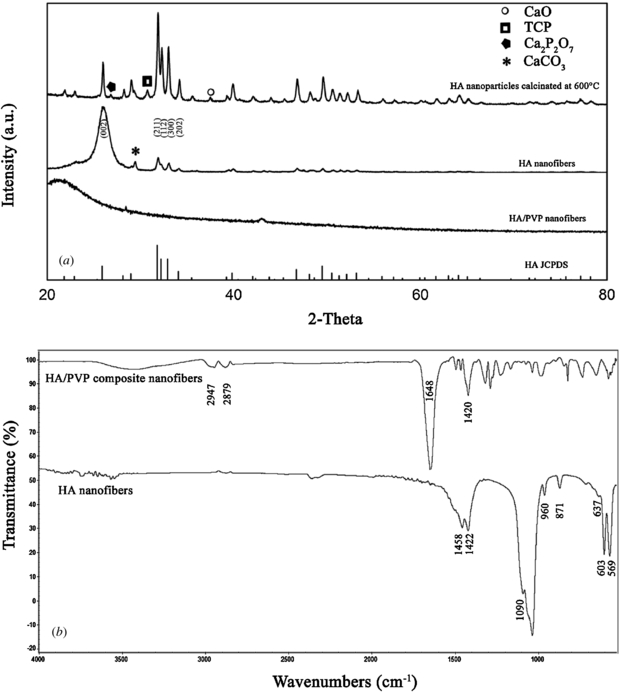
Figure 3. The XRD pattern (a) and ATR-FTIR spectra (b) of the as-spun HA/PVP fibers and HA nanofibers. The XRD pattern of HA nanoparticles calcinated at 600 °C is also given for comparison purposes. The symbols belong to the following phases; (○) CaO, (□) TCP, ( ) Ca2P2O7 and (*) CaCO3. The JCPDS file for hydroxyapatite (#9-0432) is also indicated.
Download figure:
Standard image High-resolution imageATR-FTIR spectroscopy analysis was also performed in order to confirm the chemical structure of the nanofibers before and after the calcination process. Figure 3(b) shows the ATR-FTIR spectra of the HA/PVP and HA nanofibers. The two strong peaks seen at 1420 cm−1 and 1648 cm−1 are the characteristic vibrations of PVP and they were attributed to the CH deformation of the CH2 cyclic groups and C=O stretching, respectively. The peaks in the 2800–3000 cm−1 region belong to the C–H vibrations of the methylene groups of PVP. After calcination at 600 °C, most of the bands disappeared due to the removal of PVP and decomposition of the HA precursors and characteristic HA bands were very distinct as the crystalline HA nanofibers formed upon the fusion of the nanoparticles during thermal treatment. These bands are stated as follows; the bands at 569 and 603 cm−1 belong to the O–P–O bending vibrations, 960 and 1090 cm−1 are P–O stretching vibrations, structural OH can be seen at 637 cm−1 and the peaks at 871, 1422 and 1458 cm−1 are assigned to the CO32− ions. The carbonate bands might originated from phosphate substituted HA structure (B-type carbonated HA) or be due to the CaCO3 existing as a secondary phase verified by XRD results. The obtained results are consistent with the related literature [36, 37].
TGA thermograms of the HA nanofibers, HA nanoparticles (dried after synthesis), HA/PVP fibers and PVP nanofibers are shown in figure 4. As expected, calcination of HA/PVP fibers resulted in the elimination of all organic phases and inorganic decomposition products and as a consequence, HA nanofibers do not show any weight losses, as shown in figure 4(a). The as-synthesized HA nanoparticles lost almost 40% of their initial weight (figure 4(b)). The size and weight of the HA/PVP fibrous matrices decreased upon calcination. The weight loss for the HA/PVP composite fibers were almost 80% due to the removal of the organic phase, adsorbed water and decomposition of nitrate and phosphate salts as verified by thermograms of PVP and HA nanoparticles (figure 4(c)). PVP nanofibrous matrices were completely burned out as the temperature reached to 600 °C (figure 4(d)).

Figure 4. Thermogravimetric analysis of the HA nanofibers after calcination (a), HA nanoparticles (dried after synthesis) (b), as-spun HA/PVP fibers (c) and PVP nanofibers (d).
Download figure:
Standard image High-resolution image3.2. Preparation and characterization of peptide-amphiphile nanofibrous matrices
The PA molecule used in this study is composed of five different regions and its formula is shown in figure 5(a). The first region consists of a hydrophobic domain of 16 carbons (palmitic acid), followed by covalently linked β-sheet segment of four alanine residues (AAAA), spacer segment of three glycine residues (GGG), a glutamic acid (E) for solubility and charge control and a bioactive epitope of RGD sequence. Successful synthesis of the PA-RGD was verified by mass spectroscopy and HPLC analyses. The mass spectroscopy analysis indicated that the measured molecular weight of the synthesized PA-RGD is 1167.95 ([M-H]−) where the exact molecular weight is 1169.35. According to the HPLC analysis, the purity of the obtained PA-RGD is more than 95% and this purity was favorable for in vivo and in vitro studies.

Figure 5. Chemical structure of the PA-RGD molecule (a) and TEM (b), AFM (c) images of the self-assembled PA-RGD molecules and SEM (d) image of the respective peptide gel.
Download figure:
Standard image High-resolution imageSelf-assembly and gelation of the PAs can be induced by either pH changes or charge screening by various metal ions. All the in vivo and in vitro tissue engineering applications require the materials to be a neutral pH of 7.4 and the ability of the PA molecules to self-assemble into nanofibers in the presence of calcium ions was previously described [8]. In the present study, the PA-RGD molecules have a net negative charge in neutral pH due to the availability of the glutamic acid residue, as a result these molecules were firstly dissolved in distilled water to a concentration of 10 mM (1% wt) by adjusting the pH to 7.0. The clear PA-RGD solution at pH 7.0 turns into a viscous gel, indicating that self-assembly and gelation can be triggered by the screening of the charged glutamic acid residue by calcium ions after the addition of calcium solution.
The self-assembly of the PA-RGD molecules was investigated by TEM and AFM imaging techniques. TEM images revealed that calcium-induced self-assembled PA-RGD nanofibers are in the size range of 10–12 nm in diameter and several hundred nanometers in length (figure 5(b)). On the other hand, AFM images reflects almost the same size in diameter (12–16 nm), however, the length of the nanofibers are almost more than 5 µm (figure 5(c)). This can be explained by the use of increased mole numbers of PA-RGD molecules for AFM in comparison to the TEM preparation (almost 2.5 fold more PA-RGD molecules than used in TEM analysis). Therefore, more molecules were joined together while calcium ions simultaneously produced intermolecular ion bridges during the self-assembly process, and as a result nanofiber elongation continued until all the molecules were coupled by calcium ions present in the solution. As indicated in previous studies [8, 11], these PA molecules self-assemble into hydrogels at concentrations as low as 0.25% by weight. We prepared 1% wt PA-RGD solution in this study to encapsulate cells, like in natural cell encapsulation process in tissues and organs. Figure 5(d) shows the morphology of the hexamethyldisilazane treated and air-dried nanofibrous network of PA-RGD gel upon the addition of the CaCl2 solution. This gel is composed of bundles of fibers with an average diameter of 100 ± 64 nm. A SEM image (figure 5(d)) shows that the gel has a highly porous structure and also has a high surface area to volume ratio, similar to natural ECM.
Secondary structures of the peptidic materials are an important factor when considering the morphology of the resultant product. Most of the PA nanofibers in the literature were mainly composed of β-sheet assemblies and this β-sheet structure is the main characteristic for the formation of the long cylindrical nanofibers [8]. Therefore, CD and ATR-FTIR analyses were applied to investigate secondary structure and molecular orientation of the PA-RGD molecules. The PA-RGD nanofibers exhibit a broad negative band near 216 nm and a large positive band around 191 nm as shown in figure 6(a). These data revealed that self-assembly of the obtained PA-RGD nanofibers due to the calcium addition was performed over mainly β-sheet assemblies [38]. Figure 6(b) shows the ATR-FTIR spectrum of the PA-RGD nanofibers after the addition of the calcium solution. The peak at 3280 cm−1 belongs to the amide A, where amide I band is located at 1630 cm−1, indicating that PA-RGD nanofibers adopt a mainly β-sheet structure. Furthermore, there is no secondary peak observed around 1690 cm−1 suggesting that PA-RGD molecules were stacked together as a parallel arrangement. In addition, the peak seen at 2920 cm−1 belonging to the -CH2 stretching indicates close packing of the alkyl tails in the cores of the cylindrical nanofibers. These ATR-FTIR data suggest that while hydrophobic alkyl tails formed the inner side (core) of the nanofibers, the RGD segment was presented outside of the nanofiber [8].

Figure 6. CD and ATR-FTIR spectra of the PA-RGD gel.
Download figure:
Standard image High-resolution image3.3. Formation of PA-RGD/HA nanocomposite scaffolds and cell seeding
The nanocomposite structure used in this study was composed of the both osteoinductive and osteoconductive components. RGD has long been used for the modification of biomaterials and is also found to be an osteoinductive peptide sequence by several studies in bone regeneration [39, 40]. On the other hand, HA was one of the best known materials used in both clinical, in vitro and in vivo bone regeneration studies due to its well-known osteoconductive property. Besides biocompatibility and mechanical integrity, an ideal scaffold should also be biodegradable so that it could provide enough space for newly formed bone. Although HA is known as nondegradable due to its chemical stability, its degradation rate and osteoclastic resorption was higher for HA scaffolds formed by nanocrystallites [14, 41]. Likewise, PA nanofibers are degraded by natural metabolic pathways of cells as a source of nutrients [8]. In addition to degradation issue, nanofibrous scaffolds with a high surface area to volume ratio and high porosity have an advantage in the field of tissue engineering, as they can successfully mimic native ECM.
One of the main drawbacks related to PA scaffolds are their poor mechanical properties. Different amino acid sequences resulted in different gelation times, however, the final product is generally not as mechanically stable as the cells need for 3D support. As a result, bioactive PA molecules are frequently used for coating of biomaterials such as titanium implants [42], stainless steel surfaces [43], electrospun scaffolds [44] etc. The osteoconductive component used in this study contains calcium carbonate which is soluble in culture media. Free calcium ions released from the HA matrix improved the mechanical integrity of the nanocomposite scaffolds due to the higher cross-linking of the PA molecules. Therefore, the combination of the HA matrix and PA takes advantage of their easy manipulation in cell culture in addition to their osteogenic properties.
3.4. Cell culture studies
3.4.1. Cell proliferation
Cell proliferation and metabolic activity of the scaffolds was investigated by MTT assay up to 18 days as shown in figure 7. For the first 7 days, no significant cell metabolic activity increase was observed for any kind of scaffold (p > 0.05). This behavior can be explained by the lag phase of the cell proliferation due to the low cell to cell interaction as a result of the lower cell seeding density. In addition to seeding density, three-dimensionality of both the scaffolds could also affect the cell–cell interactions due to the higher surface area with respect to tissue culture polystyrene (TCPS), because the adaptation period for the same number of cells cultivated on TCPS lasted for only 3 days (data not shown). Once the culture period reached day 14, cell proliferation was more distinct for all scaffolds, as observed by an almost three-fold increase in optical density for each type of scaffold between 7 and 14 days. At day 14, the cells in PA-RGD scaffolds exhibited statistically higher absorbance values compared to the HA and PA-RGD/HA scaffolds (p < 0.05). Furthermore, the progression of proliferation was still observed between the 14th and 18th days of culture, indicating both scaffolds support cell attachment, adhesion and later on, proliferation. Again at day 18, the cells in PA-RGD scaffolds exhibited statistically higher absorbance values compared to the HA (p < 0.001) and PA-RGD/HA scaffolds (p < 0.05). The differences between the absorbance values of HA and PA-RGD/HA scaffolds at day 14 and 18 were not statistically different.
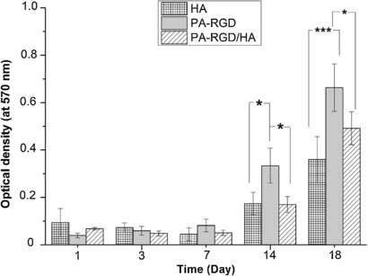
Figure 7. MTT results of preosteoblastic MC3T3-E1 cells performed at 1, 3, 7, 14 and 18 days of culture. Data are expressed as mean value of triplicate samples and error bars as the standard deviation. Statistically significant differences are denoted by symbols; * p < 0.05 and *** p < 0.001.
Download figure:
Standard image High-resolution image3.4.2. Cellular morphology
Cellular morphology and cytoskeleton organization of the MC3T3-E1 preosteoblasts on HA, PA-RGD and PA-RGD/HA scaffolds was examined by fluorescence microscope up to 14 days of culture period, as shown in figure 8. For this analysis, cytoskeletal F-actin was stained green with Alexa Fluor 488 phalloidin while nuclei of the cells were counterstained red using propidium iodide. Firstly, all the cells seemed healthy during the culture period which means cells were attached, spread well on these scaffolds and later on, continued proliferation. As verified by MTT analysis, more cells were observed on both scaffolds at day 14 as compared to day 7. The lowest number of cells were observed on the HA nanofibrous matrices during the culture based on the numbers of nuclei counted as shown in figures 8(a) and (d). These cells exhibited elongated morphology containing unorganized F-actin stress fibers with lower density as compared to the cells in PA-RGD and PA-RGD/HA scaffolds. Although the cell density was lower on HA scaffolds, cell–cell interactions are still pronounced even though there are long distances between the cells which means they are still in contact with each other and deliver the necessary information for cellular processes. Our previous studies have shown that cell adhesion and proliferation on RGD-immobilized 3D scaffolds either in flat or fiber form were higher compared to the neat surfaces [45, 46]. Furthermore, osteoprogenitor cells encapsulated in 3D PA-RGD hydrogels exhibited better attachment, proliferation and osteogenic differentiation with respect to the hydrogels without RGD sequence or 2D TCPS [12]. As a result, higher numbers of cells were attached and proliferated inside the scaffolds composed of RGD-bearing peptide gels (PA-RGD and PA-RGD/HA) (figures 8(b) and (c)) and in particular, PA-RGD scaffolds contain the highest number of cells both at 7th and 14th days as shown in figures 8(b) and (e). These results are consistent with the cell proliferation analysis accomplished by MTT assay.

Figure 8. Fluorescent micrographs of the MC3T3-E1 cell on HA, (a) and (d); PA-RGD, (b) and (e) and PA-RGD/HA, (c) and (f) scaffolds at day 7 and 14, respectively. Cytoskeletal F-actin was stained green with Alexa Fluor 488 phalloidin while the nuclei of the cells were counterstained red using propidium iodide. Magnification is ×40 for all micrographs.
Download figure:
Standard image High-resolution imageOsteoprogenitor cells cultured in normal media normally exhibit fibroblast-like morphology with parallel actin stress fibers and the cell shape change to the cuboidal morphology in differentiation medium [47]. This reflects the organizational changes on cell morphology while the cellular processes drives the osteogenic differentiation [48]. A robust, criss-crossed pattern of actin cytoskeleton seen especially on the PA-RGD and PA-RGD/HA scaffolds was the pivotal indicator of the osteogenic differentiation of MC3T3-E1 cells as shown in figures 8(e) and (f). These results indicate that osteogenic differentiation was present on both scaffolds at day 7 and proceeded throughout the whole culture period. It was also seen that although the cells were seeded inside the PA-RGD gel and encapsulation was successfully accomplished, cells also migrated to the HA part (images not shown here). These cells proliferated between HA and PA-RGD, also on the HA component indicating that cells keep in contact with both organic and inorganic components. Therefore, it can be concluded that PA-RGD/HA nanocomposite structure is biocompatible and supports osteogenic differentiation by the presence of RGD sequence and HA nanofibers.
SEM analysis was performed at day 7 (figure 9) in order to confirm the biocompatibility of the scaffolds used in this study where morphology and cellular behaviors were pivotal indicators in the differentiation process. The cells are more elongated on HA matrices where they could communicate with each other even in the long distances which existed between them (figures 9(a), (b) and (c)). Apatite crystals ∼ 5 µm in size produced by the differentiated cells were observed (inset image shown in figure 9(d)). In the case of PA-RGD matrices, cells were attached and well spread inside the peptide gel. More cells were observed in figures 9(e), (f) and (g) and cells were almost covered and produced their ECM. This can be explained by the availability of the RGD sequences that induced cellular proliferation via integrin mediated cell adhesion. Cells were actively in contact with PA-RGD nanofibers where there were more cellular extensions observed (inset photo figure 9(h)). The similar cellular morphologies were observed on PA-RGD/HA composite scaffolds (images not shown) and these results are very consistent with the MTT analysis and also ALP activity data.

Figure 9. SEM images of MC3T3-E1 cells on HA and PA-RGD matrices. (a), (b) (c) and (d) belong to the HA scaffold observed at different magnifications and different locations where (e), (f), (g) and (h) show the cellular morphology of the cells on PA-RGD scaffold observed at different magnifications and different locations. Inset high magnification images of the MC3T3-E1 cells on HA (d) and PA-RGD (h) matrices were highlighted in the appropriate SEM images.
Download figure:
Standard image High-resolution image3.4.3. Osteogenic differentiation
3.4.3.1. ALP activity.
Generally, preosteoblasts maintain their proliferative capacity while expressing many of the proteins related with the mature osteoblast phenotype, including ALP and osteopontin [49]. ALP is an enzyme produced by the osteoblasts to adjust the local concentration of the phosphate ions. This is why ALP activity analysis has been widely used for early detection of osteoblastic differentiation [3]. In this study, early osteogenic differentiation of MC3T3-E1 cells was analytically performed by the determination of the ALP activity up to 14 days. In figure 10, HA and PA-RGD/HA scaffolds showed significantly higher ALP expression than that of the PA-RGD scaffold on day 7. The difference of ALP expression levels between HA and PA-RGD/HA scaffolds is not significant. Then, the ALP activity on both scaffolds decreased to minimum expression levels on day 14 and their differences are not significant. As reported before [50] mineralization was started following the matrix maturation once the ALP was produced and showed the highest level of expression. After that time, ALP expression level decreased to the minimum, suggesting that MC3T3-E1 cells could be progressing towards mineralization for both scaffolds. Although most of the studies reported that peptide coated HA disks or scaffolds showed higher ALP activity compared to the uncoated one, osteogenic differentiation was promoted more on especially RGD functionalized HA matrices due to the better cell adhesion and proliferation [51, 52]. However, in this study we have found that the presence of HA is more dominant on osteogenic differentiation of preosteoblastic MC3T3-E1 cells as compared to the presence of specific cell adhesion sequence, RGD.

Figure 10. ALP activities of preosteoblastic MC3T3-E1 cells performed at 7 and 14 days of culture, respectively. Data are expressed as mean value of triplicate samples and error bars as the standard deviation. Statistically significant differences are denoted by symbols; * p < 0.05, ** p < 0.01 and *** p < 0.001.
Download figure:
Standard image High-resolution image3.4.3.2. RT-PCR analysis.
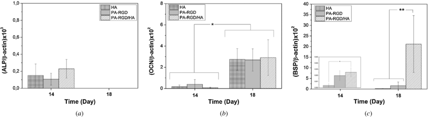
Osteogenic differentiation of the MC3T3-E1 cells was further investigated by monitoring the expression levels of three bone specific genes, ALP, OCN and BSP at days 14 and 18 as shown in figure 11. All the quantified expression levels were normalized to the internal standard of the β-actin gene to compare the results. Several successive complex events are involved in bone formation that contains the sequential cascade of collagenous and non-collagenous matrix protein production and its subsequent calcification [53]. ALP is known as one of the main intermediate osteogenic differentiation marker preparing the ECM for subsequent mineralization stage. Once the ALP expression level started to decrease, OCN is maximally expressed as a late-stage marker. As can be seen from the figure 11(a), all the scaffolds showed some amount of ALP expression at day 14 and their expression levels are similar (p > 0.05). At day 18, there was not any ALP expression detected for all groups. While the ALP expression levels decreased, MC3T3-E1 cells expressed significantly higher OCN at day 18 compared to day 14 for both scaffolds (p < 0.05) (figure 11(b)). In addition to gene expression data, a sharp decrease in ALP activity between 7 and 14 days (figure 11(a)) suggests that preosteoblastic MC3T3-E1 cells have been driven through the early osteoblastic differentiation stage to the late osteogenic differentiation state after 7 days of culture period. We also performed BSP gene expression analysis in order to see the effect of nanocomposite scaffold on mineralization stage. BSP is a phosphorylated non-collagenous protein expressed in only mineralized tissues such as bone, dentin, cementum and newly formed bone [54]. It is a key regulator for bone mineralization by binding to the HA crystals, therefore triggering HA nucleation [55]. OCN and BSP gene expressions by MC3T3-E1 cells were generally increased on apatite containing scaffolds up to 4 weeks [56]. In our study, BSP expression on the scaffolds is very low at day 14 but 66-fold, 81-fold and 850-fold increases were observed for HA, PA-RGD and PA-RGD/HA scaffolds between day 14 and 18, respectively. As shown in figure 11(c), the BSP expression level is almost ten-fold higher on a PA-RGD/HA nanocomposite scaffold with respect to HA and PA-RGD scaffolds (p < 0.01). The elevated expression of BSP on PA-RGD/HA nanocomposite scaffolds suggested a higher mineralized matrix on nanocomposite scaffolds. As it was evidenced, calcium phosphate based scaffolds without any cell specific proteins have a lack of good adhesion and better adhesion and osteogenic differentiation was obtained due to the presence of RGD sequences [57]. In addition, the synergistic effect of both specific cell adhesion sequence (RGDS) and HA nanoparticles on human MSCs were proved by long term cellularity and higher expression levels of osteoblast-related genes [58]. However, there are several sets of controversial data presented in the literature which are related to the effect of RGD concentration on several cell types. Hennessy et al [59] investigated the performances of RGD coated HA implants and their study showed that RGD has a detrimental effect on stem cell adhesion and survival. As the RGD concentration on implants was increased to a higher value, lower amounts of serum proteins such as fibronectin and vitronectin were attached to the implants, which therefore resulted in poor cell–biomaterial interactions. Overall in our study, we observed that even proliferation of the MC3T3-E1 cells is better inside the PA-RGD scaffold and better osteogenic differentiation was achieved on PA-RGD/HA nanocomposite scaffolds based on the gene expression and ALP activity results.
Figure 11. Quantitative gene expression analysis by RT-PCR for (a) alkaline phosphatase (ALP), (b) osteocalcin (OCN) and (c) bone sialoprotein (BSP) at 14 and 18 days. The y-axis represents the gene expressions normalized to β-actin. Data are expressed as mean value of triplicate samples and error bars as the standard deviation. Statistically significant differences are denoted by symbols; * p < 0.05 and ** p < 0.01.
Download figure:
Standard image High-resolution image
4. Conclusion
An ideal scaffold should fully mimic both the chemical and physical properties of native bone by means of osteoinductivity and osteoconductivity. Generally, while osteoinductivity of a composite material is supplied by natural polymers and/or several growth factors, an osteoconductive structure can be obtained by HA nanoparticles. In this study we developed a novel nanocomposite scaffold (PA-RGD/HA) by the integration of electrospun-HA fibers and RGD-bearing PA nanofibrous gel. This scaffold offers following advantages: (i) it resembles the fibrous structure of ECM, (ii) it has both of osteoconductive and osteoinductive properties, (iii) it has enough mechanical stability during manipulation and cultivation and (iv) it is biodegradable. Cell culture studies showed that PA-RGD/HA nanocomposite scaffolds strongly supported osteogenic differentiation of MC3T3 preosteoblasts. In conclusion, this nanocomposite structure with enhanced similarity to the natural bone ECM can lead us to develop clinically suitable ceramic-hydrogel composites for bone tissue regeneration.
Acknowledgment
This study was financially supported by Turkish Scientific and Research Council (TÜBİTAK) project no. 112M442.