
Abstract
When looking for novel, simple, and energy-efficient solutions to engineering problems, nature has proved to be an incredibly valuable source of inspiration. The development of acoustic sensors has been a prolific field for bioinspired solutions. With a diverse array of evolutionary approaches to the problem of hearing at small scales (some widely different to the traditional concept of 'ear'), insects in particular have served as a starting point for several designs. From locusts to moths, through crickets and mosquitoes among many others, the mechanisms found in nature to deal with small-scale acoustic detection and the engineering solutions they have inspired are reviewed. The present article is comprised of three main sections corresponding to the principal problems faced by insects, namely frequency discrimination, which is addressed by tonotopy, whether performed by a specific organ or directly on the tympana; directionality, with solutions including diverse adaptations to tympanal structure; and detection of weak signals, through what is known as active hearing. The three aforementioned problems concern tiny animals as much as human-manufactured microphones and have therefore been widely investigated. Even though bioinspired systems may not always provide perfect performance, they are sure to give us solutions with clever use of resources and minimal post-processing, being serious contenders for the best alternative depending on the requisites of the problem.
Export citation and abstract BibTeX RIS

Original content from this work may be used under the terms of the Creative Commons Attribution 4.0 license. Any further distribution of this work must maintain attribution to the author(s) and the title of the work, journal citation and DOI.
1. Introduction
Bioinspired hearing requires a fundamentally different design paradigm. In nature, the peripheral sensory organs, the eyes, ears, or skin, are rarely passive recorders of their environment. They possess complex filtering, processing, and encoding functions that are built in to the material and structure at every level: from the atomic, through the cellular, to tissue structure, and organ structure. Such signal processing can be mechanical, such as the decomposition of sound into frequency bands that is famously performed by the mammalian cochlea [1], or the result of inter-cellular chemical or electrical communication [2], but a distinct characteristic is that the signal transduction and signal processing functions are integrated and inseparable. This necessity is enforced by the sparse, event-driven nature of signals transmitted to higher brain centres [3]. The signal complexity is limited to what may be encoded in the temporal pattern of a spike train [4].
In contrast, engineered sensors view transduction as a separate function. The transducer's output is a continuous in the time-domain, rather than event driven. This 'raw' signal must be appropriately filtered, encoded and efficiently transmitted in order to extract useful information. If we could borrow nature's trick of integrating this signal processing into the structure of the transducer we could unlock significant improvements in energy-efficiency, signal latency, bandwidth reduction, and device footprint. All of these areas are critical constraints on sensor networks [5], internet of things [6] and human wearable and implantable sensors [7].
Three of the most basic problems faced by animals and shared across species are the following [8–11]:
- Distinguishing conspecific communication from predator sounds.
- Localising the position of a potential prey, predator, or mate.
- Detecting weak sound signals that deteriorate as they propagate in their natural environment.
Body size compounds the complexity of these issues: sound emission and detection efficiency tend to decrease with the size of the acoustic sensor, the ability to locate sounds (and predators) when listening diminishes with diminishing space between the sensors, and that the frequency band available for communication is limited by predation and by the acoustic transmission properties of its environment [12]. The evolutionary adaptations to the physics of acoustic waves provide unique solutions to reducing the energy (and metabolic) cost of detection, to frequency decomposition, and to locating sound sources with miniscule available directional cues from the sound field. Acoustic systems at the micro-scale may draw particular inspiration from insect hearing and communication due to the constraint of insects' small body size.
Using sound to locate potential mates and to avoid predators is a common evolutionary tactic, with hearing in insects known to have evolved independently between 15 and 20 times [13]. The methods of detection can be grouped into pressure detection systems and particle velocity detection systems. In general, particle velocity detection systems are hair-like near-field, low-frequency mechano-receptors, reliant on light weight and high specific surface area in order to translate the velocity dependent viscous drag force into a detectible vibration [14]. They are often used to detect low frequency sound (less than 500 Hz) or reactive flow in the near field of an emitter, such as the mosquito antenna which is used to detect the flight disturbance from a nearby mate [15]. This paradigm has, however, been challenged recently by evidence that mosquitoes can in fact behaviourally react to sounds up to 10 m away [16]. Pressure receivers are exclusively tympanal systems, operating in the far field [17] and capable of detecting sound into the far ultrasound range [18].
Gathering inspiration from the way these problems are solved in nature has proved to be a successful path towards innovative engineering solutions. Thus, the motivation of this review is to provide a comprehensive compilation of the mechanical solutions implemented in technology that are inspired by insects and further encourage bio-inspiration as a source for innovative engineering solutions.
The body of this paper is structured in three distinct sections, each one referring to one of the three fundamental aforementioned problems. In addition, each section is divided in two subsections. The first one concerns some paradigmatic insect solutions for its corresponding problem and the second one covers engineering solutions arising from bio-inspiration of said insects.
The section 2.1 refers to spatial frequency decomposition and comprises some example cases of how insects deal with this problem and the technological solutions inspired by it. The section 3.1 verses on the direction of arrival estimation and it covers some of the most notable nature example solutions and the sensors inspired by them. Lastly, the section 4, active hearing, follows the same structure of natural examples and technology inspired by them. A section 5 finishes the manuscript.
2. Tonotopy
Frequency discrimination can be a matter of life and death for an organism. Sound communicates information. The purpose of all acoustic systems in biology is to get that information to the animal to elicit the appropriate behavioural response. One information component of sound is its frequency, and as much as the animal's survival and reproduction can depend on the organism's ability to distinguish key frequencies from its environment. Not doing so could mean a moth failing to evade the approaches of a predatory bat [19–21] or a female cricket failing to localise the position of a potential mate [22, 23].
2.1. Spatial frequency decomposition: cochlea and tympana
All ears must translate acoustic energy travelling through a medium, usually air, into mechanical motion, and then to electrical impulses. Electrical impulses are generated by neurons and, in acoustics specifically, by auditory mechanoreceptor cells, neurons with mechanically gated ion channels that require an acoustic-mechanical stimulus to fire an action potential [24]. Frequency selectivity is a difficult aspect of insect communication, since the spike train from a sensory neuron cannot encode frequency information in their signal. To have a means of discriminating frequencies, multiple such neurons must be individually tuned. A very simple ear, such as those of moths cannot passively distinguish between the frequencies of a predatory bat and the call of a potential mate, relying instead of differentiating the temporal structure of the mating call and the pulses of a bat's echolocation [25]. Individual tuning of multiple cells can be achieved by the arrangement of the neurons according to a morphological gradient. Morphological variation of a substrate—for example, some areas being thicker, thinner, wider, or narrower—in the cells' proximity can cause different points on the substrate to move differently according to the input frequency. This frequency-specific maximal displacement of the point, if coupled somehow to a sensory neuron, can in turn stimulate that neuron independently, thus tuning the cell to a single frequency. This place-based frequency decomposition is called tonotopy.
A second problem is that of the acoustic environment, since mating calls must compete with the potentially masking calls of other species without unnecessarily attracting the attention of predators [26]. These mating calls are frequently pure tone signals, reflecting their reliance on resonant structures to transmit the necessary power to attract a mate as well as the need to seek unoccupied space in the locally available acoustic spectrum [27]. This places some constraints on the available communication bandwidth, since the resonant frequency is determined by the size of the radiator and, in order to transmit efficiently, the resonant structure should have a diameter approaching half of the signal wavelength [28]. There is a reproductive and survival advantage from the ability to distinguish the frequency composition of predators and competing species. In flagellar systems such as the mosquito [29], as well as some tympanal systems such as the tree cricket Oecanthus henryi [30] and the Noctuid moth [31], this frequency tuning is achieved by active amplification where the mechanosensory cells can produce sufficient power to drive the ear at the frequency of interest. This strategy is discussed in section 4. In this section, we discuss dispersive frequency decomposition, where sound travels and is localized to particular sites based on its frequency.
Dispersive frequency decomposition relies on a travelling wave, which is typically a flexural mode on the thin medium. The most well-known example of this is the travelling wave associated with the basilar membrane of the mammalian cochlea [32, 33]. An acoustic impulse applied to the narrow end of the wedge-shaped structure encounters a stiffness gradient. The wave shoals, increasing in amplitude whilst also slowing down until finally maximal vibration of the membrane is reached at a specific point along the membrane's length; afterwards, the wave rapidly decreases in amplitude. High-frequency stimuli terminate at a point near the narrow end, and those of lower frequency, near the wide end. Sensory neurons arranged linearly along the length of the substrate respond accordingly: a mechanoreceptor cell at a narrow region is activated only by a high frequency stimulus; a cell further along only responds to a lower frequency.
In contrast to vertebrates, among invertebrates, tonotopic systems are considerably rarer, and yet invertebrates also showcase the most diversity of system design. Moreover, invertebrate tonotopy is less understood and provides greater scope for novel discovery. Such ears can be categorised into two types, cochlea-type tonotopic systems and tympanal tonotopic systems. Both are exemplified by the bushcricket and the locust, respectively.
The bushcricket ear appears to possess the only insect cochlea yet identified [38], although some sort of cochlea analogue has been hypothesised for the cricket [39]. Bushcrickets (also known as katydids) are orthopterans, alongside crickets and grasshoppers, the latter including locusts. Their two ears (one on each of their two front legs) consist of two external tympanal membranes on either side of the leg, making four eardrums in total. Features of the bushcricket ear are reminiscent of the vertebrate peripheral auditory anatomy in terms of function. These include the tympanal plate, possibly functioning as a middle ear; and the crista acustica, the bushcricket's inner ear or cochlea [40] (see figure 1).
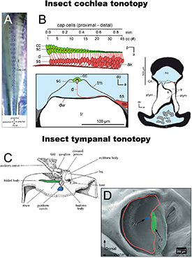
Figure 1. (A) Bushcricket crista acustica stained with methylene blue [34]. Reproduced from [34]. CC BY 4.0. (B) Anatomy of the crista acustica [35]. Used with permission of John Wiley & Sons - Books, from [35]; permission conveyed through Copyright Clearance Center, Inc. (C) Anatomy of the four locust mechanoreceptor attachment points on the underside of the tympanum [36]. Adapted to highlight the same points shown in the adjacent image, (D). Used with permission of The Royal Society (U.K.), from [36]; permission conveyed through Copyright Clearance Center, Inc. (D) SEM of the external surface of the locust tympanum [37]. Red outline: thin membrane; green outline: thick membrane; blue feature: attachment point of mechanoreceptors tuned to high frequencies; green highlight: attachment area of low frequency sensors. Used with permission of The Company of Biologists Ltd., from [37]; permission conveyed through Copyright Clearance Center, Inc.
Download figure:
Standard image High-resolution imageThe most noticeable characteristic of the bushcricket crista acustica is its tapered shape and orderly arrangement of sensilla (figure 1(A)). The 25 or so sensory neurons are tonotopically arranged from high frequency tuned cells at the narrowest tip of the organ (up to and above around 50 kHz) to those tuned to lower frequencies its wider end (tuned from about 6 kHz) [41]. These sensors lie on a thin wall of a cuticular cavity, the anterior tracheal branch. Their dendrites project upwards dorsally, and each connects to a cap cell which is itself attached to a thin sheet that covers the entire organ, the tectorial membrane. Notably, the size gradient of these cap cells is correlated with the tonotopy. Nevertheless, the correlation is not strong enough to account for the full resolution of frequency representation. Rather, the tonotopy may require another morphological gradient such as features of the sensors themselves [35]. This arrangement appears to facilitate a travelling wave across the tectorial membrane, differentially stimulating the sensory cells according to frequency. The wave is initiated at the organ's narrow end and travels along the membrane towards the low frequency tuned sensors, terminating closer to the wider tip at low frequency impulses and closer to the point of initiation at higher frequencies [34].
The other type of tonotopic mechanism is not at all like a cochlea, and in fact has no comparison among the vertebrates. In tympanal tonotopic systems, known in the locust [37] and in the cicada [42], the tympanum, responsible for sound capture, is also responsible for frequency decomposition; both functions occur at the same substrate. This dual functionality requires the eardrums to be unusually complex, and indeed the locust tympanal membrane may be considered the most sophisticated tympanum yet identified.
Locusts have two tympana, one on each side of their abdomen. Around 70 mechanoreceptor cells attach to the underside of each tympanum, forming Müller's organ, a ganglion of sensilla divided into four groupings. Three of these are tuned to low-frequency bands (3.5–4, 4, and 5.5–6 kHz) and one to high frequencies (12–20 kHz) [36, 47]. Each sensory group is secured to its own specific morphologically unique tympanal feature (figure 1(C)). In addition, the locust eardrum exhibits further, larger-scale heterogeneity in the form of two parts to the tympanum, a thin membrane and a smallerthicker membrane (figure 1(D)). High-frequency mechanoreceptors attach to a point on the thin region, whereas the others connect to fixtures of the much thicker membrane [37, 48]. Thus, a degree of morphological gradation is provided, enabling travelling waves. When stimulated with sound, a travelling wave is initiated in the thin membrane that maximally vibrates the tympanum at one of the four locations, depending on the stimulus frequency. At frequencies above 10 kHz, no movement of the thick membrane is detected. Rather, the travelling wave terminates at the high-frequency attachment point, rapidly attenuating when reaching the thicker cuticle. As such, there is a clear spatial frequency decomposition of high and low frequencies [37].
2.2. Bio-inspired frequency discriminating sensors
Engineered systems based on spatial frequency decomposition frequently target sub-Nyquist rate sampling as the value of their system [49]. An analogue to digital converter has a maximum sampling rate, and increasing this sampling rate lowers signal-to-noise ratios and increased power requirements [50]. A signal which is already filtered can be captured with lower sampling frequencies, and yet retain a higher effective sampling rate that can be significantly compressed by only retaining content when it is above a threshold. This strategy has been applied using electronic filter banks [51], and even converted to an output spike train to mimic the event-driven format of nerve conduction [52]. Mechanical filtering of the signal can be grouped into solutions using an array of resonators (figures 2(A) and (D)) [43, 46] or solutions using a tapered membrane [53].

Figure 2. Array of resonator approaches to mechanical tonotopy (A) Single crystal PMN-PT cantilevers with interdigitated electrodes [43] Reproduced from [43], with permission from Springer Nature. (B) Dual sided cantilever array [44] Reproduced from [44]. CC BY 4.0. (C) Clamped-clamped array with triboelectric transduction [45]. Bottom row shows solutions to achieving desired frequency while maximising surface area for mechanical sensitivity. Used with permission of John Wiley & Sons - Books, from [45]; permission conveyed through Copyright Clearance Center, Inc. (D) Tapered clamped-clamped beam array [46]. Reproduced from [46]. © 2013 IOP Publishing. Reproduced with permission. All rights reserved.
Download figure:
Standard image High-resolution imageResonator arrays perhaps are the most obliquely connected to the natural inspiration, but they are simple to implement on silicon as arrays of cantilevers (figure 2(B)) [44] or clamped-clamped beams (figure 2(C)) [45]. The resonant frequency of each channel can be adjusted by changing the length of the beam; and transduction of the signal may be accomplished by piezoelectric [54, 55], triboelectric [45] or optical means [56]. While relatively easy to implement, using a beam as a method of acoustic capture is extremely inefficient for lower frequencies due to diffraction around the relatively narrow beam width. The pressure difference between the front and back sides of the cantilever is small, resulting in maximum displacements at resonance in the order of tens of nanometres [57]. The resultant electrical transduction and signal-to-noise level are also prohibitively small since the cantilevers may not rely on capacitive sensing through an electrical backplate, as in a traditional microphone, due to the impact of thin film damping on both the mechanical sensitivity of the device and the resonance frequency [58, 59]. Piezoelectric sensing can be used with the ceramic element implemented either on the upper surface with interdigitated electrodes [43], or by fabricating the cantilever as a bimorph [60]. However, both strategies produce piezoelectric charge sensitivities in the order of femto-Coulombs per nm. One strategy to overcome this limitation in micro-electromechanical system (MEMS) consists of using a thickened or disc-shaped central region in the arrays, maintaining a thin base region for the purposes of keeping a desired resonance frequency while maximising the surface area for acoustic capture (figure 2(E)) [61].
Frequency decomposition based on tapered membrane structures is closer to bio-inspired sources, consisting of a single membrane with significant acoustic dispersion to isolate the frequency bands. Such systems have two fundamental requirements: there must be a time-dependent pressure gradient along the membrane to support flexural wave propagation, and the wave velocity must change along the length of the membrane. The support of a travelling flexural wave can be achieved by having a defined, highly localized sound input point, analogous to the oval window in the mammalian cochlea (figure 3(A)) [53, 62], or by ensuring the membrane length is between 1/6 and 1/4 of the frequency range of interest to ensure a phase difference across the membrane surface (figure 3(B)) [63, 64]. Both solutions have limitations, since restricting the sound input to a single point restrains the power that may be captured by the device, and tailoring the membrane length to the phase difference in the incoming sound wave either requires prohibitively large membranes or a highly restricted high-frequency range of interest.

Figure 3. Continuous membrane approaches to tonotopy, which have one single graded sensing area with a localized transduction mechanism. (A) Hydromechanical model of the basilar membrane with silicon oil backing [53], [53] Copyright (2005) National Academy of Sciences, U.S.A. (B) Fluid backed tonotopic sensor using PVDF as the membrane with individual measurement points [64]. Reprinted [64], Copyright (2010), with permission from Elsevier. (C) Luminescent tapered membrane showing some frequency separation at very low frequencies (a), (b) 110 Hz; (c), (d) 80 Hz; (e), (f) 40 Hz [54]. Reproduced from [54]. CC BY 4.0.
Download figure:
Standard image High-resolution imageThe second requirement for acoustic dispersion is equally challenging to meet within the constraints of MEMS systems. The most obvious source of generating dispersion is through the tapering of the thickness of the membrane, based on an Euler–Bernoulli model of a thin plate where the bending wave speed may be given by [65]:
where ρ is the density, ω is the angular frequency, E is the Young's modulus, ν is the Poisson's ratio, and  is the thickness profile. In theory, for every frequency, there is a height below which the wave speed will drop to the point where it is no longer transmitted, or at least may be assumed to be sufficiently attenuated, analogous to the acoustic black hole effect described by Mironov and Pislyakov [66]. In practice, the variation in thickness would need to be two orders of magnitude over the length in order to separate frequency bands in the acoustic range using a common MEMS material such as single-crystal silicon.
The more commonly seen model varies the width of the membrane along its length, which should not result in variation of the phase velocity [67]. Instead, such systems rely on the membrane being placed on a closed channel, or either air or some fluid medium, such as water [68] or silicon oil [64]. The variation of the velocity of fluid flow in this channel generates a variation in the velocity potential [69], and hence the local pressure on the membrane; while the depth of the fluid channel increases, the fluid loading on the membrane reduces the resonance frequency (figure 3(C)) [70]. This, in combination with the slight spatial variation of the membrane's first-order resonance peak with frequency, results in some degree of tonotopy. Despite the size of these membranes, over 5 cm in length, they have extremely low mechanical responses at the resonance of less than a micron displacement and are only able to separate a few, widely separated frequency bands with poor spatial confinement compared to examples in nature.
3. Directionality
The localization of sound sources by small animals is a fundamental problem in bioacoustics. Where body size is diminutive and inter-ear distance is short, an animal cannot rely on comparison between the intensity difference or time delay of signals received at either ear. For many animals, the detection of a sound is sufficient. For example, all but one of the 10–12 independent origins of hearing in Lepidoptera occurred later than 65 Ma, the currently accepted date for the appearance of echolocation in bats [71]. The hearing that evolved in these moths is extremely simple, consisting of only 1–4 neurons per tympanum [72], minimum tuning over a broad frequency range [73], and limited or no directionality, yet it remains highly effective for escaping predatory bats [74]. Moths exposed to bat echolocation signals exhibit random evasive movement, diving towards the ground if in flight and freezing behaviour if running on the substrate [75]. Knowing exactly where the bat is coming from does not change the moth's response and it is not worth the evolutionary cost of developing directional hearing. For an insect on the other face of the prey-predator relationship, for parasites, or for finding the source of a conspecific mating call, it is necessary also to know the direction of the source of the sound.
Bilateral symmetry means that most animals have two ears, one for each half of their body (one notable exception is the praying mantis, which possesses only one ear [76]). Directional hearing in larger animals may be achieved by inter-aural intensity differences (IIDs), where sound shadowing from the body creates an appreciable level difference between the ears; or inter-aural time differences where the basis of comparison is the time difference of arrival between the ears. For an insect where the body length is a fraction of the wavelength of a relevant sound source, the acoustic shadow is minimal, and time differences of arrival may be measured in nanoseconds [77].
This section looks exclusively at tympanal hearing systems, as systems which have the closest analogy to the traditional microphone. Particle detection hearing systems are inherently directional, responding to the velocity vector of the sound field however such systems are far less sensitive to far-field sound and higher-frequency sound fields.
3.1. Direction of arrival estimation from tympanal structure
Ormia ochracea has undoubtedly inspired the greatest number of engineering designs which seek to mimic the unique coupling mechanism between its tympana. O. ochracea is a fly parasitoid of crickets, locating its host Gryllus by phonotaxis to the cricket's mating calls [78]. The auditory system of O. ochracea has long been of interest to researchers due to the uncanny accuracy with which it can locate the host call, a 5 kHz pure tone with a wavelength of over 10 times the body length of O. ochracea and 100 times the separation between the insect's tympana. This insect has directionality down to an accuracy of 2° in the azimuthal plane [77]. The system consists of two diaphragms mechanically connected by a bridge and pivot allowing the transfer of energy from the motion of one diaphragm to another (figures 4(A) and (D)) [79]. When the stiffness of this connecting bridge is correctly tailored to the system, the signals from the stimulating sound wave and the linked companion diaphragm will constructively interfere with the ipsilateral sound source and destructively interfere with the contralateral sound source. The result is what was termed by Robert et al [80] mechanical interaural phase difference and mechanical IID which can be 40 times higher than the phase difference in the stimulating sound field. Much of the research into Ormia-inspired systems targets applications in hearing aids [81, 82]; however, there is an inherent conflict: the Ormia's coupled ears are a resonant system and so single-frequency, while hearing aids, or teleconferencing applications require broadband sound source localization.

Figure 4. (A) Micro-CT images of tympanal system of O. ochracea. Arrays of Ormia inspired membranes [83]. Reproduced from [83]. CC BY 4.0. (B) four coupled membranes [81] © [2018] IEEE. Reprinted, with permission, from [81]. (C) Array of 3 see-saw style Ormia membranes [84]. Reproduced from [84]. CC BY 4.0. (D) Illustration of rocking and translational mode along with standard two degree of freedom model of the Ormia system [80]. Reproduced from [80], with permission from Springer Nature. SEM images of Ormia membranes targeting low acoustic frequencies using (E) silicon-on-insulator MEMS [83] Reproduced from [83]. CC BY 4.0. and (F) Silicon nitride patterning [85]. Reprinted with permission from [85]. Copyright [2009], Acoustic Society of America. (G) Transduction of membrane motion using capacitive comb sensing [86]. Reproduced from [86]. CC BY 4.0.
Download figure:
Standard image High-resolution imageA potentially different tactic is employed by Achroia grisella. A. grisella is a moth of the Pyralidae family within the Lepidoptera order, known as the Lesser Wax Moth. It is less than 13 mm long and principally known as a parasite of unhealthy bee colonies, on which they deposit their eggs and on which their larvae feed. The unusual aspect of Achroia is the use of ultrasonic calling as a mating signal, and their use of phonotaxis rather than anemotaxis to track their preferred mate [87]. As discussed in the introduction to this section, simple hearing systems are widespread among nocturnal Lepidopters, but evidence of directional response is sparse save for some limited negative phonotaxis in Noctuids [88]. In contrast to hearing, acoustic communication in moths is rare and occurs only among isolated species and genera in the three major clades [71]. In many cases, acoustic communication is restricted to close-range courtship where directional hearing would not be critical [89]; however, A. grisella can transmit and track sound signals over distances over 2 m, making a sound localization capability expected. Unlike O. ochracea, whose acoustic perception of host crickets has probably evolved de novo, A. grisella already had an evolutionary ancient system for perceiving sound, and the mechanism for localization reflects an adaptation of the tympana as bat detectors to a new purpose [90, 91].
The tympana of A. grisella are located ventrally on the first abdominal segment (figure 5(A)). They are oval-shaped, between 500 μm and 550 μm long in the females and divided into an opaque anterior section and a transparent posterior section (figure 5(B)) [92]. These two sections of the tympana oscillate in anti-phase when there is no variation in the pressure field across the tympanum (i.e. when the sound wavefronts are planar), with a large peak in displacement near the neuronal attachment point [73, 93, 94]. This vibrational mode remains relatively stable with sound source angle until a 100 kHz sound source is located along the major axis of the tympanum at which point the peak in displacement near the attachment point grows sharply in magnitude [91].

Figure 5. (A) Illustration of the ear location and orientation on the first abdominal segment of A. grisella [94]. Reproduced with permission from [94]. (B) x-ray CT voxel images of the structure of the tympanum showing the scolopale attachment point in the centre of the lower section of the tympanum [102]. © [2022] IEEE. Reprinted, with permission, from [102]. (C) Laser Doppler vibrometry measurement of A. grisella tympanal motion in response to a planar sound field and (top) and COMSOL reconstruction of the membrane (bottom) [102]. © [2022] IEEE. Reprinted, with permission, from [102].
Download figure:
Standard image High-resolution image3.2. Bio-inspired directional sensors
Ormia-inspired directional microphones are undoubtedly the largest class of bio-inspired hearing sensors and, consequently, have in themselves been subject to a number of dedicated reviews [83, 95]. The overwhelming direction of design has been towards a single-layer see-saw design realised in a silicon-on-insulator or related MEMS process, either as a single sensor (figures 4(E) and (F)) or an array (figures 4(B) and (C)) [85, 86, 96, 97]. This operates similarly to the Ormiine system, with each of the 'wings' of the device comparable to one tympanum, while the torsional stiffness of the bridge connecting the device to the substrate performs the equivalent function of the raised bridge and fulcrum in O. ochracea. The system is attractive to researchers as it is easily implemented in a multi-user MEMS process, and it can, with careful tailoring of the relative stiffness of the membrane wings and the torsional stiffness of the bridge, amplify directional cues in a similar manner to O. ochracea. This design path has several challenges which have not yet been overcome besides the inherent resonant nature of the device. The first is the signal-to-noise ratio achievable in this system. As the Ormia-inspired microphone relies on the interaction between the resonant modes, a traditional capacitive backplate is generally not used, at least partially because of the thin-film damping such a structure would introduce [84, 98]. Because the system works optimally at the frequency where the in-phase resonance and the out of phase resonance are the same power, increasing the bandwidth of these resonances necessarily means increasing the separation between the frequency peaks of the two modes. This has the effect of lowering the amplification of directional cues, but does broaden the frequency range over which this is possible [99]. Principally, designers avoid this issue entirely by incorporating optical [98] or capacitive comb-based sensing schemes (figure 4(G)) [97, 99]. The first of these adds significantly to the design complexity and cost, while both piezoelectric and capacitive comb-based methods in MEMS devices have low sensitivities [96, 100, 101].
The second obstacle to a good signal-to-noise ratio is more fundamental to the design—as the see-saw mechanism must be released from the periphery except at the anchor points, sound is free to diffract around the device. Since these devices are typically of a maximum size of 1 by 2 mm and the target sound field is in the acoustic range, the pressure difference across the membrane is minimal. This can be solved by making a more direct model of Ormia's hearing system, however so far all examples have been demonstrated at the mesoscale due to the complexity of fabricating a true 3D structure using lithographic methods [103, 104].
On the other hand, finite element modelling of A. grisella's tympana and tests on 3D-printed models have shown that this single membrane directivity pattern can be replicated in a relatively simple stepped-thickness membrane (figure 5(C)) [102].
4. Active hearing
The third central problem for insect hearing is the inherently low energy of a propagating sound wave over the length scales that the insect can hope to capture. This problem is compounded for velocity sensing organs, such as the antenna in mosquitos and fruitflies, where the mechanism for energy capture is through the viscous drag losses in the antennal hairs [105]. In order to maximise the capture of these sounds and the transduction into neuronal signals, the mechanoreceptor neurons themselves add energy to the system, resulting in a non-linear response to sound [29]. The system is analogous to the active hearing contributions of hair cells in the cochlea; however, in insects, it can be directly observed in antennal systems. The existence of active hearing can be inferred from non-linear response characteristics in tympanal systems in insects, such as otoacoustic emissions or self-generated oscillations, in tree crickets [106] and Katydids [40]; nevertheless, the small scale of these systems and the relatively low number of congregated mechanoreceptors compared to Johnson's organ in the mosquito, make these systems harder to study.
4.1. Particle velocity sensors and active hearing
The champion species for active amplification in flagellar systems is the elephant mosquito, Toxorhynchites brevipalpis. The hearing organ consists of an antenna shaft which sits within a pedicel. Mechanically, it acts as a rotational spring, causing the antenna to oscillate in a rigid body motion with a resonant frequency of between 300 and 500 Hz [107]. Within the pedicel is Johnston's organ, a collection of some 16 000 mechanosensory cells arranged in a bowl shape along the base of the antenna. These consist of a scolopale rod which connects the antennal structure to the chordotonal neuron, which both senses the motion of the antenna and can inject additional energy into the antenna's oscillations [108]. If we model this system in a sound field as a passive oscillator, it can be approximated as a damped harmonic oscillator [109, 110]. Such a system will have a defined resonant frequency and a Q factor given by the ratio between resonant frequency and damping, which gives the half-power bandwidth of the resonant response.
Mosquitoes use their auditory receptors for mating purposes, detecting the acoustic signature of a female's wing beats. The female creates an extremely weak and brief sound signal, a sound particle displacement of around 3.5 nm at a distance of 10 cm [29]. As the sound intensity varies so sharply and so quickly with the change in distance between the male and the potential mate, the mosquito requires a sensor with an extremely fast temporal response. Mechanically, this would be a broadband, low Q factor, allowing the detection of higher frequency transients in the signal. Conversely, to successfully track the female, the male must filter out environmental noise for which a broadband sensor would be a poor choice and a sharply resonant, high Q factor sensor would be preferred. The antenna's frequency selectivity in passive hearing is principally determined by the resonance of the flagellum and spring base, which is well-damped and low Q factor [107]. The mosquito maximises its tracking efficiency by switching from the initial passive response to a sharply resonant response through the generation of force in the neurons at the base of the antenna [107]. These neurons fire at twice the frequency of the antenna's sound field-driven oscillation, sharpening the tuning of the resonant frequency (figure 6(A)) [111].

Figure 6. (A) Impact of twice frequency forcing in the mosquito antenna, changing the broadband response of the antenna into a sharp narrowband response [111]. Reprinted from [111] © 2009. Frequency forcing in a MEMS microphone using piezoelectric sensing and capacitive combs to inject the motile force, (B) resultant amplification with forcing [114], © 2018 IEEE. Reprinted, with permission, from [114]. (C) SEM of the membrane design [115]. © 2017 IEEE. Reprinted, with permission, from [115]. (D) Hair sensor microphone using electrostatic transduction [121] © 2019 IEEE. Reprinted, with permission, from [121], and (E) larger scale proof of concept of same using optical sensing [122]. Reproduced with permission from [122]. © 2018 by ASME. (F) Meshed hair sensing using electrospun PVDF [123]. Reproduced from [123]. CC BY 4.0.
Download figure:
Standard image High-resolution image
4.2. Bio-inspired active amplification sensors
The concept of active Q control has found applications in atomic force microscopy [112, 113] and in optical amplifiers, where it is referred to as parametric amplification. Rather than directly injecting energy, parametric amplification involves changing some property of the system with a specific phase timing, analogous to a child on a swing. In acoustic systems, the forcing mechanism is usually directly applied to either the membrane or the flagellum through electrostatic actuation, perhaps more analogous to someone pushing a swing. At root, this is a feedback system where the oscillations of the acoustic receiver are filtered through a leaky integrate and fire stage and recombined. In practice, this has meant generating a pulsed actuation signal controlled by a computational control mechanism, designed to fire in time with the oscillations of the incoming microphone signal. A MEMS microphone directly inspired by this principle was demonstrated by Guerreiro et al (figure 6(B)) [114, 115], using capacitive combs to inject the pulsed feedback signal. This was a unipolar signal, firing only once per oscillation of the membrane as opposed to the 2:1 mode of the mosquito [111]. The Q factor of the MEMS microphone is already high in the absence of strong damping sources such as thin film damping; however, the feedback mechanism demonstrated an increase of the Q factor from 30 to 66 with a consequent amplification of 2.19 [114].
The mechanism has also been used to lower the effective Q factor in Ormia-inspired devices. As noted, MEMS devices without backplates will experience very light damping and therefore exhibit sharply resonant behaviour which can be a detriment to sound localization. The introduction of passive damping systems would increase thermal noise and reduce the microphone's fidelity. Miles et al [116] have demonstrated active Q control aimed to reduce damping, here using a proportional and differential gain and feedback scheme to an electrostatic mesh, successfully broadening the resonant response without noise gain. A similar effect can be achieved with pulse train stimulation, changing the phase timing of the pulse with respect to the diaphragm oscillations [117]. Active control over the damping in this manner relies on separate methods of measurement and feedback; for example, piezoelectric measurement of membrane motion and capacitive comb feedback [118], or laser diffraction-based measurement and actuation through a capacitive backplate [119, 120].
Particle velocity acoustic sensors are relatively rarer, with the majority of the bioinspired hair sensors being directed towards the detection of fluid flow [124], and we have few examples of hair or flagellum-based sensors that are directly mosquito inspired (for example [125]), although the claimed incorporation of active feedback appears in reality to be a simple directional response. A velocity feedback controller on a cantilever beam was demonstrated by Joyce and Tarazga [126], the device was constructed at scale being a 5 cm long aluminium beam with a resonance of 10.8 Hz. Antenna-inspired acoustic sensors should have large surface area relative to their mass (or moment of inertia) and stiffness [121, 122]. This can be achieved via sub-micron diameter thickness wires, either arranged individually (figures 6(D) and (E)) [127] or in a mesh via electrospinning (figure 6(F)) [123]. This leads to a significant challenge with signal transduction since a mechanical element that is sufficiently agile to respond to the drag forces from a sound field will also be driven more powerfully by any electrostatic or capacitive field [128]. Solutions based on electrospun meshes have the convenient electrical transduction mechanism of a piezoelectric polymer [129], in this case, P(VDF-TrFE) however, due to the random orientation of the fibres, the weak reverse piezoelectric effect and the clamped-clamped nature of the mesh the return pathway would be challenging to implement.
5. Conclusion
Insect hearing systems are diverse, but there are common sets of problems that all small animals must deal with: size and energy. This tells us the type of problems we should be approaching with an insect-inspired solution. A system that uses a locust or bushcricket-inspired mechanical tonotopy will not outperform a well-designed digital filter in terms of frequency decomposition, but it will enable a low-power solution and reduce the data transmission needs by lowering the necessary sampling frequency. Directional sensors that make use of Ormia or Achroia-inspired directional membranes will not be more accurate than a well-spaced and sampled microphone array, but they will achieve the directionality in a fraction of the space. Only the active hearing processes are truly unique, having no digital equivalent that can change the response pattern of the sensor itself. There is great potential for this approach as we begin to consider autonomous sensors and remote 'fit-and-forget' networks for structural health monitoring, environmental monitoring or health monitoring purposes. The great difficulty thus far is in our ability to reproduce the mechanical functions of natural materials such as cuticle and resilin and to develop a reliable method of transducing the signal captured.
In summary, bio-inspired solutions are one of the most innovative and useful approaches to engineering design that prioritises energy and resource efficiency rather than the best performance possible, and have the potential to become even more so in the future as our knowledge of the principles behind biological solutions widen and our manufacturing capabilities improve.
Lara Díaz-García: Writing—Original Draft. Brendan Latham: Writing—Original Draft. Andrew Reid: Writing—Original Draft. James Windmill: Writing—Review & Editing and Supervision.
Data availability statement
No new data were created or analysed in this study.