

Abstract
Objective. Movement control is an important application for EEG-BCI (EEG-based brain–computer interface) systems. A single-modality BCI cannot provide an efficient and natural control strategy, but a hybrid BCI system that combines two or more different tasks can effectively overcome the drawbacks encountered in single-modality BCI control. Approach. In the current paper, we developed a new hybrid BCI system by combining MI (motor imagery) and mVEP (motion-onset visual evoked potential), aiming to realize the more efficient 2D movement control of a cursor. Main result. The offline analysis demonstrates that the hybrid BCI system proposed in this paper could evoke the desired MI and mVEP signal features simultaneously, and both are very close to those evoked in the single-modality BCI task. Furthermore, the online 2D movement control experiment reveals that the proposed hybrid BCI system could provide more efficient and natural control commands. Significance. The proposed hybrid BCI system is compensative to realize efficient 2D movement control for a practical online system, especially for those situations in which P300 stimuli are not suitable to be applied.
Export citation and abstract BibTeX RIS
1. Introduction
A brain–computer interface (BCI) could enable direct access between the brain and external devices, such as a computer, wheelchair or prosthetic limbs (Yu et al 2012, Li et al 2013, Fifer et al 2014). For people with serious motor disabilities (Page et al 2005, Crosbie et al 2004, Liu et al 2004, Mulder 2007, Lebon et al 2010), the BCI provides a potential way for them to communicate with their surroundings and even express their minds to some degree (Vidal 1973, Wolpaw et al 2000). Currently, brain signals including EEG, spikes, fMRI and fNRIS have been used to construct BCI systems, among which the EEG-based BCI system has attracted wide attention due to its advantages, such as relatively low cost and mobility (Orhan 2013). According to the strategies used for BCI control, the common EEG-based BCIs could be roughly divided into two types, MI-based BCI (MI-BCI) and visual stimuli-based BCI. MI needs subjects to perform the corresponding motor imagery according to the intent, but it does not need external stimuli. MI-BCI has potential applications in important fields, such as motor function rehabilitation, due to its intrinsic relationship with the motor functions (Lim et al 2006, Mulder 2007). Visual stimuli based BCI uses special components evoked by external visual stimuli to perform task recognition, and an interface usually must be designed to provide the corresponding visual stimuli. Currently, the main visual stimuli for the BCI system include SSVEP, P300 and mVEP, and they have different application situations. SSVEP is characterized by a high SNR and does not require a training process, and it has been used to realize the fastest BCI (Zhang et al 2012b, Chen et al 2015). However, SSVEP stimuli will cause extreme fatigue in subjects because the fast repetition of the flashing stimuli, even inducing epilepsy (Gergondet and Kheddar 2015). Based on the oddball paradigm, the target is smartly designed to present with a relatively low possibility, which will evoke the P300 component when the subject focuses on the stimulus corresponding to the target by visual or auditory stimuli. In the situation of the control of multiple targets (usually more than tens), P300 shows its unique virtue, such as in the speller system. Though fatigue could be alleviated to some degree by the P300 protocol, the development of new paradigms with less fatigue even with the long utilization of BCI is still an important issue. Jin et al developed a facial expression change pattern without a sudden change in luminance or a high contrast of visual object to evoke the ERP for BCI control that has been shown to be effective in reducing the interference from adjacent stimuli and alleviating the fatigue and annoyance experienced by BCI users (Jin et al 2014). Similar to the facial expression change pattern, due to the lack of a requirement for the sudden change of luminance or a high contrast of visual objects, mVEP-based BCI may provide a softer stimulus for users (Guo et al 2008, Zhang et al 2012a, Zhang et al 2015), and the first practical mVEP BCI was reported in 2008 (Guo et al 2008). The conducted study reveals that mVEP has more stable and strong components compared with P300, especially for situations with smaller numbers of targets (Hong et al 2009).
One of the most important applications of BCI is movement control, including of a computer cursor or wheelchair (Hong et al 2009, Kaufmann et al 2014). Strictly speaking, a BCI system based on a single-modality EEG signal can only generate a 1D control command, which will result in unnatural and less efficient movement. To realize more natural control close to the actual strategy adopted by people, more and more studies have focused on the utilization of multiple EEG signals to develop a hybrid (or multi-modality) BCI system (Jun et al 2014). A hybrid BCI typically consists of two systems including at least one BCI system, and it must be used in a specific application and obtain better results than a common system (Pfurtscheller et al 2010). According to the type of single-modality that composes the hybrid system, the hybrid BCIs can be classified into two categories, one composed of two BCIs (Allison et al 2010, Jin et al 2012, Wang et al 2015) and the other composed of one BCI system and a non-BCI system (Lalitharatne et al 2013). Based on the method of operating way, the hybrid BCIs can be divided into simultaneous hybrid BCIs (Allison et al 2010, Li et al 2010) and sequential BCIs (Pfurtscheller et al 2005, Pfurtscheller and Solis-Escalante 2009). One pioneering work was to combine MI and P300 to control the cursor movement, the motivation of which is to ask the subjects to simultaneously perform the MI and P300 tasks, and the movement control is the combination of the two tasks, with MI and P300 responsible for the horizontal and vertical control, respectively. The extension of this system to other applications including website surfing (Yu et al 2012) and wheelchair control (Li et al 2013) show that it is of very high efficiency. Based on a similar motivation, other similar hybrid BCI systems, such as MI versus SSVEP (Horki et al 2011) and SSVEP versus P300 (Wang et al 2015), have also been developed for specific aims (Ko et al 2014).
Though high efficiency could be achieved by the hybrid BCI system, the hybrid BCI system requires the subjects to pay more attention to the dual tasks compared to the single-modality BCI system (Jiang et al 2014). Therefore, it is necessary to provide a more comfortable stimulus that will reduce the fatigue in subjects. Several researchers have noticed the merit of the softer stimulus of mVEP for the development of a potential hybrid BCI. Jin et al (2012) proposed a hybrid BCI system combining P300 potential and motion-onset visual evoked potential and showed that the combined approach is practical in an online BCI and yielded better performance than either of the two single approaches. Motivated by those previous studies on mVEP and hybrid BCI systems, in the current work, we developed a multi-modality BCI system by combining MI and mVEP, aiming to realize the more natural and efficient control for a cursor in a more comfortable mode.
2. Methods
2.1. Fusion protocol for MI and mVEP
2D cursor control could be theoretically realized by the sequential left, right, up and down operation. Though this type of control strategy is simple, it leads to non-smooth movement, i.e. only one movement in the four directions could be used at a time. The practical movement of the cursor needs a smooth and natural trajectory, which requires the subject to perform two tasks simultaneously. To realize this, we tried to combine mVEP and MI, one the external visual stimulus and the other the inner mind activation, to build the hybrid BCI system.
In our multi-modality BCI online system, the horizontal cursor movement is controlled by MI, and the vertical movement is based on the mVEP. Let Px(t) and Py(t) denote the x and y coordinates of the cursor at time t, and Δx and Δy represent the position increments in the horizontal and vertical directions at time t + 1. Then, the position at t + 1 could be updated as

Equation (1) reveals that the next cursor position is determined by the position updating in both the x and y directions. Therefore, Δx and Δy could influence the movement direction for the cursor, and the updating direction can be depicted in figure 1 as
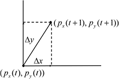
Figure 1. Updating direction of the cursor.
Download figure:
Standard image High-resolution imageFigure 1 indicates that the cursor moving trajectory is adjusted by Δx andΔy, and it needs to perform the movements in the two directions simultaneously for a smooth cursor movement. To realize this fusion, we need to recognize the motor imagery for the horizontal movement and mVEP for the vertical movement. The GUI interface for the MI and mVEP fusion is designed as figure 2.
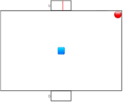
Figure 2. Stimulus interface of the multi-modal BCI online system (the red ball denotes the cursor that is controlled by the subject, and the blue square denotes the target).
Download figure:
Standard image High-resolution imageWe can see that there are two boxes located at the middle of the top and bottom, which create mVEP potentials when the subject fixes his or her gaze on the moving line appearing in one of the boxes. The two boxes control the vertical movement of the cursor: the top one would move the cursor upward, and the other located at the bottom would make the cursor move downward when the user pays attention to it. When the system starts, a red moving line begins to appear and slides from right to left in each of the two boxes successively. One cycle, in which the red moving line appears in both boxes in due order, is defined as a trial. In the current system, the vertical movement control is output every three trials, i.e. mVEP is recognized by averaging three trials. The user just needs to keep his or her eyes on the top box while neglecting the bottom one if he or she wants the cursor move upward, and vice versa. When the system detects that his or her mVEP signal features are consistent with the top (or the bottom) box, the cursor will be moved upward (or downward).
The horizontal movement of the cursor is controlled by motor imagery. The cursor moves to the left (or the right) when the system identifies a left- (or right)-hand imagery. The control mechanism is similar to that for the vertical movement: If the user want to make the cursor move left, he or she needs to imagine the movement of the left hand, and vice versa.
In this paper, one run is defined as the control of the red ball to hit the target represented by the blue box in figure 3. During each run, a ball and target will randomly appear on the screen, and the subject needs to simultaneously perform MI and mVEP to move the ball to hit the target (blue box). A run starts just when the target and the ball appear. After a preparation time of 2 s, a red moving line will begin to appear in one of the two boxes in due order with lines sliding from right to left. The appearing duration of the moving line in each box is 250 ms without an interval between the two consecutive stimuli; thus, the total stimulus time of the two boxes is 500 ms. A stimulus circle (trial) is accomplished when the moving line has appeared in the two boxes once in due order, and a 2000 ms interval for the rest is embedded after three consecutive trials. In the current work, the averaged signals of three consecutive trials are used to extract the mVEP features, and the vertical control command is thus output every 3500 ms.

Figure 3. Analysis for mVEP and MI tasks.
Download figure:
Standard image High-resolution imageThe command to control the horizontal movement of cursor is sent by motor imagery every 2000 ms, with a 6000 ms long segment to estimate the MI tasks.
Let DH and Dv represent the classifier outputs for MI and mVEP at time t, and vx and vy denote the movement velocities in the horizontal and vertical directions. The position increments Δx and Δy are

Therefore, by combining equations (1) and (2), the fusion movement tracking of the MI and mVEP could be easily estimated. In the current work, vx and vy are set as one pixel for each updating. The core of this fusion is dependent on whether the intentions for the simultaneous vertical and horizontal movements could be reliably detected, and we will introduce the feature extraction and classification methods for the two different BCI tasks in the following section. In the practical situation, considering that there may exist a delay time for the command output for the two tasks (i.e. even if the two tasks are simultaneously performed, the time needed to recognize them is different), we will combine the outputs of the two tasks to generate the fusion control if the time interval between the commands of the horizontal and vertical directions is within 700 ms.
2.2. EEG signal processing
As mentioned above, the multi-modality system consists of the independent processing for the MI and mVEP. The adopted analysis mechanisms for the two signals are shown in figure 3.
As shown in figure 3, two different analysis mechanisms are used to process the MI and mVEP signals, and the detailed information of the two analysis procedures will be given in the following sections.
2.2.1. mVEP signal processing.
mVEP shows its differentiating components more prominently in the time domain, and the typical mVEP is characterized with four main components, i.e. N1, P2, N2 and P3 (Clarke 1973, Spekreijse et al 1985, Kuba 2006). When the subject pays attention to the target box presenting with the brief movement of the visible target, the mVEP signal related to the beginning of the line movement will be evoked. The typical mVEP evoked by the attention to the target is shown in figure 4, which reveals the significantly stronger N1, P2, N2 and P3 compared to the waveforms evoked by the non-target box.
- (1)Feature extraction of mVEPmVEP commonly creates excitation potentials 200 ms after the stimulus. After three cycles (trials), a band-pass filter within 1–20 Hz is applied to filter the EEGs corresponding to the three cycles. The EEGs are further divided into 6 segments (3 circles*2 boxes) that are 500 ms long according to the onset of the moving line of each box. The 6 segments are then averaged across 3 circles according to the box index number, resulting in 2 waveforms corresponding to the two boxes. A decimation factor of 50 is used to down-sample the two averaged EEGs. According to the reported distribution of mVEP (Guo et al 2008), in the current work, the down-sampled EEG waveforms in the window of 150–300 ms in channels PO3 and PO4 are treated as features for the target recognition.
- (2)Recognition of vertical movementAfter the above feature extraction procedures, the features with dimensions of 8 can be obtained and then fed into the LDA (Kuba et al 2007, Zhang et al 2013) for the final classification. To perform the classification of the mVEP tasks, training procedures should be performed before the online recognition. The stimulus interface for the mVEP training in our online system is shown as figure 5:

Figure 4. Waveforms of the typical mVEP in the time domain.
Download figure:
Standard image High-resolution image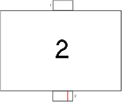
Figure 5. Stimulus interface for mVEP training.
Download figure:
Standard image High-resolution imageThe training interface consists of 2 boxes, with each box being coded with the corresponding number 1 or 2. Similar to the online system, a stimulus circle is defined as the 500 ms stimulus duration when the moving line has appeared in the two boxes once in due order. A 2000 ms interval for rest is embedded after three consecutive circles. One trial begins with a number 1 or 2 randomly appearing on the interface center for 3.5s, and the subject is asked to pay attention to the corresponding box indicated by the number. Therefore, one trial consists of three consecutive circles and a 2000 ms rest interval for the training procedure.
The training procedure consists of 72 trials, with each number (i.e. 1 and 2) appearing 36 times. The signals are pre-processed as mentioned in the above subsection Feature extraction of mVEP to extract the corresponding mVEP features. In each trial, we will obtain 2 different 8D features corresponding to the 2 modules, and the feature coming from the module consistent with the indicated number is labeled with 1 while the others are labeled with −1. The features and labels are input into the LDA to train the classifier.
Based on the trained LDA classifier, the two features corresponding to the two boxes extracted from the online system are sent to the LDA, resulting in two predicted values mv(K), K {1,2}. Then, the module with the maximum predicted value is regarded as the target, i.e. K = {K|max{mv(K), K
 {1,2}}}. Therefore, the vertical movement could be updated as

where sig(.) is the symbol function, and the vertical position at time t + 1 in equation (1) is updated as

To avoid the possible effect of the idling state on the recognition, we record a 2 min long EEG when the subject is asked to have no intention to control the mVEP system (idling state). Then, the 2 min EEG is divided into segments that are 500 ms long according to the mVEP onset time, and the segments are further averaged according to the mVEP module labels. Finally, a similar procedure as used for the mVEP feature extraction is used to extract the idling state features, and the features are input into the trained LDA, resulting in 2 LDA prediction values. The averaged values of the 2 LDA outputs are then regarded as the threshold for the idling state detection, i.e. if the maximum prediction value mv(K), K {1, 2} is smaller than this idling threshold, we will set Δy = 0; otherwise, Δy is updated as equation (3).
2.2.2. Motor imagery signal processing.
The body movements or body movement imagery of a single side lead to the decrease of the EEG power spectrum, which can be detected especially in the µ rhythm (8–13 Hz) (Thomas et al 2009). This physiological phenomenon is called event-related desynchronization (ERD) and may result from a decrease in the synchrony of the underlying neuronal populations. In contrast, event-related synchronization (ERS) may be attributed to an increase in the synchrony of the underlying neuronal populations (Pfurtscheller et al 1996, Pfurtscheller and Lopes da Silva 1999, Pfurtscheller and Neuper 2003, Szurhaj et al 2003, Pfurtscheller et al 2006). ERD/ERS is just the neuro-physiological basis of the BCI system based on the motor imagery, and the main aim of the feature extraction of MI-BCI is to detect ERD/ERS-related rhythm features
- (1)Feature Extraction of MIIn the current work, a supervised common spatial patterns (CSP) method is used to extract the MI features (Müller-Gerking et al 1999, Blankertz et al 2004, Blankertz et al 2008). To collect the EEG data to train the CSP filters, the MI training paradigm shown in figure 7 is embedded in our system.The subjects were asked to perform motor imagery with their left or right hand according to the instructions appearing on the screen (see figure 6). Each trial started with a 4s rest period. A yellow bar then appeared on the left or right side of the screen for 1s to instruct the subjects to perform the corresponding motor imagery. After the bar turned green, the subjects started to perform the requested hand motor imagery, which lasted 6 s, and the 6 s length of the task data is used as our training set. The order of the left and right bars was randomized, and the duration of each trial was 11 s. There were 50 trials per run and approximately 25 trials for each motor imagery condition. During all experiments, the subjects are required to avoid actual hand movements, and the experimental inspector will observe the subjects. When actual hand movement is observed, the experiment will be stopped and a new experiment will be started.In the current work, a 6 s long EEG that appears after the green bar is used to detect the MI related features. The EEG segment was filtered by a subject-specific optimal band-pass filter, which was obtained by r2 (Müller et al 2004, Blankertz et al 2007, Dornhege et al 2007, Xu et al 2011).The band-pass filtered EEG signals were then transferred to the three pairs of optimal spatial filters, estimated by CSP. The logarithmic transformation of the variance of the spatially filtered signal, resulting in a 6D feature vector, was used as the final features.
- (2)Recognition of horizontal movementBased on the CSP features derived from the training process, the LDA classifier is trained. Then, the MI-related signal in the multi-modality online system will be processed as follows to detect the left or right control command. The latest 6 s long EEG recording is used for the MI task recognition every 2 s. The same band-pass and spatial CSP filters determined from the training dataset were first used to filter the 6 s long online EEG signal. Then, the 6D log-variance of the filtered EEG signal was calculated as features for the MI task recognition. Let mh(t) denote the LDA output at time t, which determines the horizontal movement as


Figure 6. MI paradigm for training.
Download figure:
Standard image High-resolution image
Figure 7. Offline training interface of simultaneous tasks.
Download figure:
Standard image High-resolution imageAccordingly, the horizontal position at time t + 1 in equation (1) is updated as

Similar to the idling state detection in mVEP, a 2 min long EEG when the subject does not perform the MI task is recorded. Then, the 2 min EEG is divided into 6 s long segments. Similar procedures as used for the MI feature extraction are used to extract the features for each 6 s long idling state segment, and then the features are input into the trained LDA classifier, resulting in one LDA output for each segment. The averaged LDA outputs across all the segments are regarded as the threshold for the idling state detection of the MI task, i.e. if the absolute value of the latest LDA output is smaller than this idling threshold, we will set Δx = 0; otherwise, Δx is updated as equation (5).
2.3. Experimental protocol
2.3.1. Offline test.
The experiment consists of two steps, one in which the subjects are asked to perform the MI and mVEP tasks separately and the other in which the subjects perform the tasks simultaneously according to the cues.
The simultaneous tasks utilize the interface in figure 7. In each trial, a cue will appear in the center of the interface. Following the cue, the subjects are required to perform the corresponding simultaneous tasks. For example, if a cue 'LEFT 2' appears, the subject needs to keep his or her eyes on module 2 and perform the left-hand motor imagery simultaneously. Each trial lasts 7 s (including a 1 s length cue and 6 s length task-performing, and the 6 s length task data is used as the test set). The simultaneous task consists of 72 trials, with 18 trials in each simultaneous task (i.e. LEFT 2, LEFT 1, RIGHT 2 and RIGHT 1).
Seven subjects (six males and one female aged from 23 to 29) who showed good performances in previous single MI and mVEP experiments are selected to participate in the simultaneous experiment. Given the difference between the single-modality and multi-modality BCI experiments, the 7 subjects are first trained with the interface shown in figure 7 for approximately 1 month. After the training, the 7 subjects perform the separate MI and mVEP experiments that, respectively, used the paradigms in figures 5 and 6 for training and then perform the simultaneous tasks for offline analysis. Both the MI and mVEP tasks consist of 72 trials, with 36 trials for each target. There is a 5 min rest interval between the MI and mVEP tasks. After the single-modality experiment, the subjects are provided with another 10 min to rest and then perform the simultaneous task. All the EEG data is recorded with Symtop amplifier (Symtop Instrument, Beijing, China, 1000 Hz sampling rate, 16 channels, 50 Hz notch filter). For the MI experiment, there is also the request of avoiding the actual hand movement, similar to the offline single-modality task for each subject.
2.3.2. Online test.
After the offline experiment, the 7 subjects will rest for 20 min and then participate in the online BCI experiment using the test interface shown in figure 2. Sixteen Ag/AgCl electrodes (F3, F4, FC3, FC4, C3, C4, C5, C6, Cz, CP3, CP4, PO3, PO4, Pz, O1, and O2) from the extended 10–20 system were placed for the EEG recordings. The classifiers derived from the previous single-modality experiments (i.e. the classifiers trained with the trials in the single-modality experiment) are used to perform the corresponding classification in the online multi-modality experiment. For the MI experiment, there is a request made of each subject similar to that in the offline single-modality of avoiding actual hand movement.
To conveniently evaluate the performance in the online test, the position of the target is set in the center of the test interface at the beginning, and the initial position of the ball randomly appears in one of the four corners, which would provide the tasks with the same difficulties for all the subjects. In the control of the vertical direction, the ball will move straight upward or downward the same distance (i.e. one pixel) every time when the system detects the corresponding mVEP command. In the control of the horizontal direction, the ball will move straight to the left or right with the same distance (i.e. one pixel) every time the system detects the corresponding MI features. With such a setup, the ideal distances that the ball needs to move to the target in the horizontal and vertical directions are, respectively, 23 and 12 steps, resulting in a total of 35 steps for the single-modality task if no mistake is made during the online control.
3. Results
The hybrid BCI system proposed in the current work is evaluated from two aspects consisting of the offline test and online test. The aim of the offline analysis is to verify whether the MI and mVEP tasks could be simultaneously fully performed and the corresponding features extracted, and the online test is to evaluate the actual control performance of the hybrid BCI system.
3.1. Offline test
The established analysis procedures depicted in the section of Methods is utilized to analyze the three datasets. For mVEP, the features are extracted from the two channels PO3 and PO4 in the time window 150–300 ms. For MI, CSP is utilized for the 16 channels to extract the MI-related features, where the single MI task is based on the 6 s long EEG after the green bar appears, and the simultaneous task is based on the first 6 s long EEG after the cue is presented. A comparison is performed to investigate if the simultaneous MI and mVEP tasks could evoke the desired features to realize the BCI control. Figure 8 gives the spectrum when the subjects image the left or right hand movements in the MI task and the simultaneous tasks for subject 3.
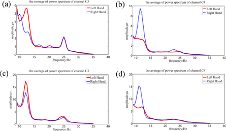
Figure 8. Spectra on C3 and C4 when performing movement imagery of left and right hands in the single- and multi-modality tasks for subject 3. (a) and (b) for the single-modality MI task; (c) and (d) for the multi-modality MI task.
Download figure:
Standard image High-resolution imageFigure 9 further shows the topology distributions of the most discriminative CSP filters (i.e. corresponding to the largest and smallest eigenvalues) for the MIs performed in different conditions for subject 3.
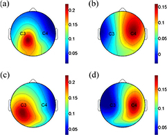
Figure 9. Scalp topologies for the most two discriminative CSP filters of one subject when performing movement imagery of left and right hands in the single- and multi-modality tasks. (a) and (b) For the single-modality MI task; (c) and (d) for the multi-modality MI task.
Download figure:
Standard image High-resolution imageThe corresponding waveforms of mVEP on the channels PO3 and PO4 are given in figure 10 for the different mVEP tasks for subject 3.

Figure 10. mVEP waveforms on PO3 and PO4 of Subject 3 when performing mVEP experiment in the single-modality and multi-modality tasks.
Download figure:
Standard image High-resolution imageThe above results consistently show that the simultaneous task could evoke MI and mVEP features similar to those evoked in the single-modality task. To further quantitatively evaluate the corresponding subject performances in the different modality tasks for the three datasets, 5-fold cross-validation is repeated 100 times to evaluate the performance in the single- and multi-modality tasks for the 7 subjects. The average accuracy of the cross-validation results is listed in table 1, where the paired t-test is performed to test whether the performances of the single- and multi-modality experiments have significant differences.
Table 1. Average accuracy of mVEP and MI for the 7 subjects in single-modality and multi-modality experiments.
| Subject | mVEP | MI | ||
|---|---|---|---|---|
| Single-modality | Multi-modality | Single-modality | Multi-modality | |
| S1 | 78.3 ± 2.1 | 82.8 ± 4.8 | 72.5 ± 6.2 | 75.1 ± 6.6 |
| S2 | 83.4 ± 3.9 | 80.7 ± 3.7 | 76.2 ± 6.3 | 78.5 ± 4.6 |
| S3 | 84.7 ± 4.8 | 77.3 ± 5.4 | 77.1 ± 5.2 | 76.4 ± 5.6 |
| S4 | 92.1 ± 5.5 | 90.1 ± 3.4 | 80.0 ± 6.4 | 79.9 ± 4.3 |
| S5 | 85.2 ± 4.6 | 86.5 ± 3.7 | 78.3 ± 4.3 | 80.0 ± 4.4 |
| S6 | 81.3 ± 5.0 | 84.2 ± 3.6 | 67.5 ± 5.9 | 73.5 ± 5.5 |
| S7 | 90.4 ± 3.9 | 88.3 ± 2.8 | 79.6 ± 5.8 | 78.2 ± 6.0 |
| Mean ± Std | 85.1 ± 4.3 | 84.3 ± 3.9 | 75.9 ± 5.7 | 77.4 ± 5.3 |
The performance in table 1 shows that there is no obvious difference when subject performs the single- and multi-modality tasks (p > 0.05, paired t-test), which proves that the characteristic components of MI and mVEP could be simultaneously evoked and detected in the multi-modality experiment.
3.2. Online evaluation for multi-modality BCI
Each subject performs 4 tests with 5 min interval between two consecutive tests, and the ball is randomly initially positioned at any of the four corners. For each test, we record the number of steps moved by the subjects to reach the target. Table 2 lists the detailed performance for the 7 subjects.
Table 2. Actual steps and time used by subjects in the multi-modality online experiment.
| Test# | Number of steps | Time(s) | ||||||||||||
|---|---|---|---|---|---|---|---|---|---|---|---|---|---|---|
| Sub1 | Sub2 | Sub3 | Sub4 | Sub5 | Sub6 | Sub7 | Sub1 | Sub2 | Sub3 | Sub4 | Sub5 | Sub6 | Sub7 | |
| 1 | 31 | 29 | 28 | 29 | 29 | 35 | 24 | 58 | 54 | 49 | 52 | 54 | 60 | 48 |
| 2 | 28 | 28 | 32 | 29 | 29 | 42 | 27 | 52 | 53 | 56 | 49 | 54 | 70 | 50 |
| 3 | 28 | 28 | 28 | 29 | 28 | 28 | 24 | 53 | 49 | 49 | 52 | 53 | 49 | 48 |
| 4 | 28 | 28 | 24 | 28 | 28 | 30 | 29 | 53 | 53 | 48 | 52 | 49 | 53 | 54 |
| Mean ± Std | 28.8 ± 1.5 | 28.3 ± 0.5 | 28.0 ± 3.3 | 28.8 ± 0.5 | 28.5 ± 0.6 | 33.8 ± 6.2 | 29.0 ± 2.5 | 54.0 ± 2.7 | 52.3 ± 2.2 | 50.5 ± 3.7 | 51.3 ± 1.5 | 52.5 ± 2.4 | 58.0 ± 9.2 | 50.0 ± 2.8 |
| Overall Mean ± Std | 29.0 ± 3.4 | 52.6 ± 4.5 | ||||||||||||
From table 2, we can see that all 7 subjects can move the ball to reach the target with a smaller number of steps than in the single-modality, and the overall average for the 7 subjects is 29, with an approximately 6 step reduction compared with in the single-modality. The time used by the 7 subjects to fulfill the simultaneous tasks is also given in table 2, which shows that almost all subjects could accomplish each test within 60 s. Moreover, the time is consistent with the step number shown in table 2 that when more steps are moved, more time is spent. In our online experiment setup, the expected movement trajectory of the ball is in the diagonal direction, and the actual trajectories of one subject in the four tests are shown in figure 11, from which we can see that it really follows the diagonal direction.

Figure 11. Movement trajectory of the ball in four tests of one subject.
Download figure:
Standard image High-resolution image
4. Discussion and conclusion
The flexible control of the cursor needs multi-tasks to be performed simultaneously (Li et al 2010). In this paper, we designed a hybrid BCI online system based on MI and mVEP, where MI is used to control the horizontal movement of the ball and mVEP is responsible for the vertical movement. The key to the hybrid BCI system is that the corresponding signal components should be independent and could be evoked at the same time (Li et al 2010). The recognition of the MI task is fundamentally based on the ERD, which is mainly reflected in the spectrum. As shown in figure 8, the ERD located at approximately 12 Hz can be clearly revealed in both the single MI task and multi-modality task, where the obvious difference could be observed between the right- and left-hand movement imagery. Moreover, the spatial filters extracted from the two tasks show similar topology distributions in which the electrodes around C3 and C4 are heavily emphasized, which is consistent with the CSP patterns reported in previous MI studies (Faller et al 2012). For mVEP, the task recognition is based on the characterized peak components including N2 and P3 in the time domain. Therefore, the quality of the waveform largely determined the system performance. Figure 10 shows that the mVEP waveform evoked in the multi-modality task is close to that evoked in the single mVEP task, and the characteristic N2 and P3 can be clearly observed in both tasks. Despite the similarity between the two mVEP waveforms, the mVEP in the simultaneous task actually shows relatively weaker components compared to those in the single mVEP task. This indicates that the simultaneous tasks are actually more difficult than the single-modality task because the attentional resources are divided between two different tasks. (Yin et al 2015). Consistent with the similarity features revealed by figures 9 and 10, the offline performance in table 1 further proves that the subject's performance in the multi-modality task did not decrease significantly, with MI accuracies of 75% and 77% (p > 0.05) and mVEP accuracies of 85% and 84% (p > 0.05) for the single and simultaneous tasks, respectively. All those results consistently demonstrate that the desired signal features (i.e. ERD for MI and N2 and P3 for mVEP) could be simultaneously evoked in the multi-modality tasks. The MI training in the current hybrid BCI system is in a cue-paced manner. After a long training, the brain may partially unconsciously generate the related EEG pattern when the subjects see the cue (i.e. left-side bar or right-side bar in the current work) (Pfurtscheller et al 2008), and it is somewhat similar to a stimulus-evoked response while not from the actual MI cognitive process. Future work will design a self-paced MI training paradigm that may generate conscious MI EEG patterns under conditions much closer to free will.
The online experiment further proves the feasibility of the multi-modal MI and mVEP system toprovide the effective control of the cursor. In practice, the consecutive MI and mVEP could also control the ball to reach the target, and the movement trajectory is composed of separate vertical and horizontal movements, resulting in an unnatural movement trajectory. Theoretically, the smallest number of steps needed to control the ball to reach the targets for the single-modality BCI control is 35 under the extreme condition that the subjects perform all the controls correctly, which is very difficult in the online BCI system. However, if the subject could perform the simultaneous tasks to control the vertical and horizontal movements at the same time, the control steps needed to complete the task could be dramatically reduced. Table 2 actually shows that the total mean steps to complete the task is 29 by the multi-modality BCI control, which is a 6 step reduction compared to the ideal single-modality control. Specifically, the online experiment setup determines that the diagonal direction is the shortest path to the target. The actual trajectories in figure 11 reveal that the simultaneous task can provide more natural movement for the cursor, one that is very close to the diagonal path. Carefully investigating the trajectories in figure 11, we could find some vertical or horizontal lines existing in the moving path, which indicates that the subjects failed to perform the expected simultaneous task (i.e. either of mVEP or MI features is not reliably detected) and subjects control the ball movement in a conventional single modality way. Even with the special long training, especially in a relatively long simultaneous control task like the ball control in current work, it cannot guarantee that the subjects can fix their attention and perform the simultaneous task totally successfully for every control. But the movement along diagonal direction contributed by the simultaneous task can actually improve the control efficiency for the movement. In actual BCI applications, an open issue is the individual variability, which has been reported in various studies including SSVEP (Martinez et al 2007), P300 (Sellers et al 2006), MI (Guger et al 2000) and mVEP (Hong et al 2009). The proposed hybrid BCI in the current work also reveals the large variability that exists among subjects, where table 2 reveals that the step number varies from 24 to 42. This individual variability is an obstacle for the practical application of BCI, and it needs to be carefully considered in future studies.
The current work describes a new hybrid BCI system combining MI and mVEP. Both the offline and online analysis consistently demonstrate its feasibility to realize the more natural 2D control of cursors. In the current BCI studies, hybrid BCI is a promising strategy to improve the efficiency, and there exist various types of hybrid BCI systems, among which the most successful is the system combining MI and P300 developed by Li et al (2010). mVEP is very similar to P300 for its reliable components, such as N2 and P3. For visual P300-based BCI, the inter stimulus interval (ISI) and the occurrence probability of the target are both important factors affecting the BCI performance. Therefore, it is necessary to carefully select a suitable ISI and simultaneously construct a stimulus paradigm with a lower occurrence probability of the target, aiming to build an efficient visual P300 BCI for the specific applications. Considering the 2D cursor control in the current work, two freedom degree controls are needed for the vertical movement, and only two flashing boxes are theoretically needed. However, when the two-target visual P300 paradigm is used, the evoked P300 may be weaker compared to the multiple-target P300 system (Gonsalvez and Polich 2002), which may lower the control efficiency. Compared to the visual P300 paradigm, mVEP has no such requirement for the low target occurrence probability, and mVEP is kept relatively stable under various stimuli conditions. Therefore, only two flashing boxes can encode the vertical movement efficiently. Because the number of flashing boxes is directly correlated with the BCI efficiency (i.e. more flashing boxes will need more time to complete one stimulus circle), mVEP may provide a more efficient hybrid system for the actual application, such as 2D cursor movement. Moreover, the stimulus to evoke mVEP requires no sudden change of the luminance or a high contrast of visual objects; thus, the subjects may experience less visual fatigue and feel more comfortable when using this hybrid BCI system. However, we must admit that when the control target is of a larger number, P300 may provide more reliable control, as proven in the speller system. Though more natural control could be provided with the hybrid BCI compared to the conventional single-modality BCI, the hybrid BCI will need subjects to perform multiple tasks simultaneously, which will impose a greater mental burden on them. The special extra training is usually necessary for subjects to adapt to the simultaneous tasks in the hybrid BCI system (Amiri et al 2013). For the proposed mVEP versus MI hybrid BCI, the training will require that subjects form a rationale strategy that allocates more attention resources to the MI while gazing at the target visual mVEP stimulus module with less attention resources.
Acknowledgments
This work was supported in part by the National Nature Science Foundation of China (#61522105, #81330032) and the 863 project 2012AA011601.