


Abstract
The recent emergence of topological insulators in condensed matter physics has inspired analogous wave phenomena in mechanical systems. However, to date, the design of these mechanical systems has been limited mostly to discrete lattices or perforated structures. Here, we take a ubiquitous design of a bolted elastic plate and demonstrate that it can guide flexural waves crisply around sharp bends. We show that this continuum system eliminates unwanted in-plane plate modes and allows the manipulation of low-frequency flexural modes by exploiting the local resonance of the bolts. We report the existence of a pair of double Dirac cones near the resonant frequency of the bolts, one of which leads to the creation of a topological complete bandgap that forbids all the plate modes. These findings open new possibilities of managing multiple wave modes in elastic solids for applications in energy harvesting, impact mitigation, and structural health monitoring.
Export citation and abstract BibTeX RIS
1. Introduction
The discovery of topological insulators in condensed matter physics has prompted a new notion of topology in association with the intrinsic dispersion behavior of a material [1, 2]. By using this concept, one can characterize the dispersion behavior of an infinite 'bulk' material, which consequently provides a tool to predict the response at the 'boundaries' of a finite material. This 'bulk-boundary correspondence' leads to a topologically protected boundary response of a non-trivial bulk, thereby offering a degree of robustness. At the physical level, the topological insulator has thus shown an exotic state, in which a robust and directional current flows along the material's boundary, while it is forbidden in the bulk.
This tool of topology has paved a way for researchers to control the flow of energy in other areas, such as photonics [3] and acoustics [4–7]. It has also given an impetus to a new way of designing elastic systems [8–19]. These topological structures—mostly in the setting of discrete lattices or perforated structures—aim at manipulating elastic vibrations and offer a tremendous degree of flexibility in controlling their dynamic responses. Therefore, these prototypical systems are excellent candidates for tabletop designs, in which topological physics can be systematically investigated [20]. However, one of the outstanding challenges in the topological manipulation of elastic systems is to have control over several types of wave modes that can exist in elastic solids, particularly in a low-frequency domain. This becomes even more relevant when one goes beyond the discrete lattice models and considers continuum structures such as plates. Though a judicious manipulation of plate modes has been shown in high frequencies [21–23], a simple design of low-frequency waveguiding remains yet challenging. Conventional designs thus far tend to focus selectively on certain plate modes, and therefore, are prone to energy leakage through other modes [24–27].
A natural question is whether there exists a way to manipulate flexural plate waves at low frequencies yet avoiding the wave leakage into other modes. This can be of significant importance, because low-frequency flexural modes typically carry high vibrational energy. Their efficient manipulation can be useful for several engineering applications, such as energy harvesting, vibration isolation, and structural health monitoring. However, lowering the operating frequencies generally demands large lattice sizes due to the Bragg condition. This can pose challenges especially under stringent size limitations of wave media. Recent studies in photonics [28] and acoustics [29] have proposed the use of resonating elements within a topological medium to lower the operating frequencies. In elastic systems, recent numerical investigations have provided novel solutions to these issues [26, 30, 31]. However, the experimental realization of topological manipulation of low-frequency elastic waves remains a formidable challenge to date.
Here we propose a ubiquitous design of bolted plates to tackle the aforementioned challenges. This strikingly simple design complements the topological physics in a continuum elastic plate with the mechanism of local resonance of bolts [32]. The design is rich in physics as it allows not only the out-of-plane coupling between the mounted bolts and the plate, but also the interweaving of their bending with in-plane modes. This results in a simultaneous effect of guiding low-frequency flexural plate modes and removing unwanted in-plane modes. To achieve this, we employ the zone-folding technique [33] to invoke the C6 symmetry-protected pseudo-spin Hall effect and manipulate flexural waves by strategically arranging the bolts on the plate. Remarkably, this bolted plate system forms a pair of double Dirac cones [34] in the low-frequency range of the bolt's bending resonance. We numerically investigate the opening of multiple topological bandgaps by manipulating the bolt arrangement on the plate, one of which is notably a complete bandgap (CBG) that prevents the leakage of flexural waves into other modes. We experimentally verify the efficient waveguiding capability of this bolted plate along a path with sharp bends, when excited at frequencies inside these topological bandgaps.
2. The locally resonant topological plate
2.1. Design and fabrication
Our system consists of a thin plate and bolts that are tightly fastened to form a periodic pattern. As a starting point, we take a hexagonal lattice pattern shown in figure 1(A). We focus on a large unit-cell representation, i.e. a rhombus-shaped unit cell (lattice constant a = 45 mm) that contains six bolts to facilitate zone-folding. We then perturb this unit cell by varying the circumferential radius R of the mounted bolts around R = a/3 (figure 1(B)). This is to obtain two topologically distinct unit-cell configurations of the bolted plate. Note that, in the process, we keep the C6 symmetry intact in the unit cell, so that we obtain degenerate modes in the dispersion to be shown later. These two types of unit cells, specifically  and
and  in this study, are then tessellated to form a periodic pattern in the plate (figure 1(C)). We construct a domain wall consisting of three linear segments (one horizontal and two inclined at 60◦) by joining these two types of periodic patterns (figure 1(D)).

Figure 1. System configuration. (A) A hexagonal lattice arrangement with the unit cell containing six elements. The corresponding first Brillouin zone (FBZ) is indicated. (B) This unit cell is perturbed around R = a/3 to obtain two topologically distinct unit cells. Bolts act as local resonators mounted on a thin plate. (C) A snapshot of the actual system with multiple bolts mounted on the plate. (D) The experimental setup, in which a domain wall is created between two topologically distinct lattice patterns in yellow and violet. The plate is excited by a piezoelectric actuator positioned at the center, and out-of-plane velocity is measured point-by-point by an LDV mounted on a two-axis linear stage.
Download figure:
Standard image High-resolution imageThe substrate is an aluminum 6061-T6 plate (91.4 × 61.0 cm and thickness t = 2 mm). We use a CNC milling machine to drill 1320 holes, followed by manual tapping and fastening M4-0.7 mm black-oxide alloy steel bolts (91290A180, McMaster-Carr). To facilitate the firm contact between the bolts and the threads of the plate, we add a drop of glue (Henkel Loctite adhesive) in the process of mounting bolts using a screwdriver (movie 1 is available online at stacks.iop.org/NJP/20/113036/mmedia). The partial thread on the screws comes handy, as it allows tightening them firmly on the plate without using any additional nuts.
2.2. Experimental measurements and processing
To excite the system, we bond a piezoelectric ceramic disc (STEMiNC, diameter 10 mm, and thickness 1 mm) with silver epoxy adhesive on the plate as shown in figure 1(D). We mount the Polytec OFV 534 laser Doppler vibrometer (LDV) on the two-axis linear stage and control its motion using MATLAB to measure vibrations on the plate. The LDV takes point-by-point measurements by moving in a square grid of 7.5 × 7.5 mm. We measure 114 points horizontally and 60 points vertically, i.e. a total of 6840 points. All measurements are synchronized with respect to the onset of the input voltage signal from the function generator, which sends a signal to the piezoelectric actuator via an amplifier. To get the steady-state transmission profiles, we send a 100 ms wide frequency sweep signal from 2 to 40 kHz. Then, we employ fast Fourier transformation on the time-history obtained by each measurement and construct a 2D transmission profile for a frequency slice. To get the transient wavefields, we send a Gauss-modulated sine pulse with 80 cycles at a given center frequency. We apply a bandpass filter around the center frequencies to eliminate ground noise on the plate. Then, we use a cubic interpolation on the measured grid data for a better visualization of wavefield on the plate.
2.3. Numerical modeling
We use commercial finite element software (COMSOL Multiphysics) to perform numerical simulations. We take nominal material properties of the aluminum plate (Young's modulus E = 68.90 GPa, density ρ = 2700 kg m−3, Poisson ratio ν = 0.33) and steel bolts (Young's modulus E = 210.60 GPa, density ρ = 7800 kg m−3, Poisson ratio ν = 0.30). See appendix A for the geometric details of the bolt. The threaded contact between the bolt and plate is modeled using a simple approach, which captures the realistic contact stiffness by modeling an effecting contact area (see appendix B). We mesh the model with tetrahedral elements. To obtain the dispersion diagrams, we take a unit-cell and apply Bloch–Floquet boundary conditions and solve for eigenfrequencies along the irreducible Brillouin zone.
3. Results
3.1. Unit-cell dispersion and band inversion
In figure 2, we numerically show dispersion diagrams for the unit-cell configurations with radii varying across R = a/3. The colormap indicates the polarization index defined as  , where Vu is the plate volume in the unit cell, and ux, uy, and uz are the displacement components in x, y, and z axis, respectively. Pz would be close to 1 for out-of-plane plate modes and near 0 for in-plane plate modes. For R = 0.8a/3, we observe two distinct bandgaps in the range of 6.2–8.5 kHz in figure 2(A). Clearly, the polarization index confirms that the bandgaps are for out-of-plane modes (blue markers). The lower bandgap is a partial bandgap (PBG) because it supports nearly in-plane modes (S0 and SH0) shown with red and yellow markers. Notably, the upper one is a CBG. This is because the bending-dominated local resonance of the bolts occurs near 6.9 kHz (see the horizontal blue markers in figure 2(A)), and it is coupled with in-plane modes of the plate (further explanations to follow next). This results in a locally resonant bandgap (see the two-sided arrow) for 'undesired' in-plane modes (red and yellow markers) in the range of 6.9–9.4 kHz. Consequently, we observe a CBG between 6.9 and 8.5 kHz for all plate modes.
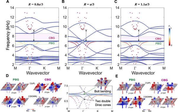
Figure 2. Presence of multiple bandgaps and their inversion in the unit-cell dispersion. (A) A case with R < a/3 leading to the emergence of two bandgaps. The color of the markers indicates the polarization of plate mode, i.e. it is nearly 1 for out-of-plane and nearly 0 for in-plane plate modes. The lower bandgap is a partial bandgap (PBG) due to the presence of other nearly in-plane plate modes. The upper bandgap is a CBG for all plate modes. The two-sided arrow indicates the locally resonant bandgap for in-plane modes. (B), In the hexagonal lattice arrangement, i.e. R = a/3, these bandgaps close and form two distinct double Dirac cones. A zoomed-in view is in the inset below to show the bolt bending mode between two double Dirac cones. (C) When R > a/3, the two double Dirac cones open again to form two distinct bandgaps. (D) The mode shapes (out-of-plane) at the Γ point for the bandgaps shown in (A). Γ(UP) and Γ(DOWN) indicate the upper and the lower edges of the bandgap, respectively. Note that two degenerate p-type modes have smaller frequency than two degenerate d-type modes for both bandgaps. (E) The mode shapes at the Γ point for the bandgaps shown in (C). These mode shapes are inverted with respect to the ones shown in (D).
Download figure:
Standard image High-resolution imageThis is an example of judicious engineering of overlapping two types of bandgaps: locally resonant bandgap for in-plane modes and Bragg bandgap for out-of-plane modes in the same system. We call the later Bragg bandgaps because those emerge solely when the translational symmetry in the system is changed by varying the radius across R = a/3. This point can be further justified if we plot the dispersion diagram for the case of the perfectly hexagonal system, i.e. with R = a/3, in figure 2(B). We observe that both bandgaps (denoted by PBG and CBG above) close. However, the bandgap for in-plane modes (red markers) remains intact, because it is a locally resonant bandgap caused by the local bending of the bolts, which we do not change in the process (see the two-sided arrow). Remarkably, near the resonant frequency of the bolts, we observe the formation of a pair of distinct double Dirac cones (see the panel below figure 2(B) for the zoomed-in view of the dispersion curves along with the mode shape of the resonant bolts). To the best of the authors' knowledge, the creation of such multiple double Dirac cones at different frequencies in an elastic system has not been reported in the literature.
In figure 2(C), we plot the dispersion diagram for the case when we further increase the unit-cell radius to R = 1.1a/3. We choose this radius to avoid the bolts approaching too close to the unit cell boundary, and at the same time to ensure an overlap with the bandgaps established in  (compare the locations of bandgaps between figures 2(A) and (C)). We observe that the two double Dirac cones open again and form two bandgaps. However, these are different from the ones observed in figure 2(A) in terms of topology. For further investigation, we revisit figure 2(A), examine the out-of-plane mode shapes, and plot them in figure 2(D). For the lower bandgap, i.e. PBG, we extract the mode shapes of its edges at the Γ point. We observe that two p-type modes are degenerate at the lower edge, i.e. Γ(DOWN), and two d-type modes are degenerate at the upper edge, i.e. Γ(UP). Naturally, the d-type modes show prominent bending of the bolts, approaching the vicinity of local resonance region around 6.9 kHz. A similar pattern is observed for the upper bandgap (CBG) as well, wherein d-type modes are at the upper edge. Sandwiched between these two regions are the locally resonant bending modes of the bolts.
In figure 2(E), we plot the mode shapes at the aforementioned band edges at the Γ point, but for the configuration with  shown in figure 2(C). A similar degeneracy of modes is observed. However, p-type modes are at higher frequencies than d-type modes for both bandgaps. This so-called band-inversion is a crucial ingredient of the topological phenomena at work and makes this configuration topologically non-trivial. This mechanism is reminiscent of the pseudo-spin Hall effect in photonics [33], where the degeneracy of p- and d-type modes is used for creating two counter-propagating pseudo-spin modes at the domain wall between two topologically distinct unit cells. Here we realize this effect for a flexural wave at a low-frequency regime (i.e. in the vicinity of the bending mode of the bolts) in a continuum plate.
3.2. Emergence of topological interface state
Now moving to the multicell configuration, we first take a supercell consisting of eight unit cells of each type and join them to form a domain wall as shown in figure 3(A). We apply a periodic boundary condition in parallel to the domain wall to investigate the wave dynamics of this tessellated system. We keep the other boundaries free. In figure 3(B), we show the eigenfrequencies of the supercell as a function of wavevector k//. The colormap indicates the localization index for out-of-plane wave modes. This is defined as  , where Vs is the entire plate volume of the supercell and Vs* is the plate volume of two unit cells touching the domain wall (see the enclosed cells in figure 3(A) with a darker solid line). The high value of the localization index in the colormap clearly highlights the presence of localized modes at the domain wall (red markers) inside both bandgaps (PBG and CBG). The modes in the upper region are desolate as expected in the complete bandgap. However, the localized modes in the lower region are populated with other modes in this partial bandgap.
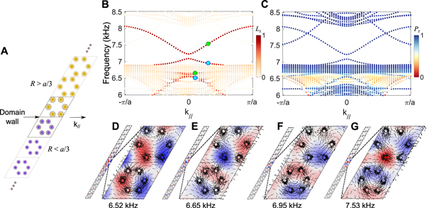
Figure 3. Emergence of topological modes at the domain wall. (A) A supercell made by placing two topologically distinct lattices adjacently at the domain wall. (B) Eigenfrequencies of the supercell versus k//, the wavevector parallel to the domain wall. The colormap indicates the localization index (Lz). Higher the value it has, the more localized are the out-of-plane modes at the domain wall. The upper region (i.e. CBG) shows clear localized modes. The lower region (PBG) also shows localized modes, but those are mixed with other extended modes. (C) The same eigenfrequencies diagram, but with a different colormap to show the polarization of plate modes. It denotes 1 (0) for out-of-plane (in-plane) plate modes. (D)–(G) Localized out-of-plane mode shapes at some selected frequencies inside PBG and CBG (marked by circles in (B)). The arrows indicate the time-averaged mechanical energy flux to confirm their spin nature.
Download figure:
Standard image High-resolution imageTo verify the polarization of these localized modes, we replot figure 3(B) in figure 3(C) but with a different colormap indicating the wave polarization, as was used in figure 2. We clearly observe that the localized modes at the domain wall are out-of-plane modes (blue markers). Again, the upper region shows clean out-of-plane modes. The additional branch in this bandgap corresponds to the modes at the other ends of the supercell, and therefore is not of any important considerations here. The lower region, however, shows weaker out-of-plane localized modes, and those are intermixed with other in-plane modes (red and yellow markers). This fact leads us to understand the difference of topological wave localization between PBG and CBG. The advantage of having the CBG is evident as it facilitates a clean wave localization at the domain wall and eliminates the possibility of wave leakage into other modes. Note in passing that there is a small gap at the k// = 0 point in both regions, where there is no localization at the domain wall. As highlighted in the previous studies [26, 33], this is due to the breakage of the C6 symmetry at the domain wall. By employing engineering tricks, such as a slowly-varying (i.e. gradient) domain wall, one can also reduce this small gap at the k// = 0 point and impart greater protection to the topological modes.
We proceed to investigate the mode shapes of the aforementioned localized modes. We plot out-of-plane displacements at selected frequencies marked as circles in figure 3(B). Figures 3(D), (E) correspond to the frequencies inside PBG, and figures 3(F), (G) correspond to the frequencies inside CBG, all arranged in the order of increasing frequencies. It is clear that these modes are localized at the domain wall. Insets show zoomed-in views of the mode shapes on which the superimposed arrows indicate in-plane time-averaged mechanical energy flux ( , where σij and vj are stress tensor and velocity vector, respectively) over a harmonic cycle. It is evident that these modes have spin characteristics. More specifically, in figures 3(D), (F) that correspond to the cyan markers in figure 3(B), we observe clockwise spins. In figures 3(E), (G) (corresponding to the green markers in figure 3(B)), we witness counterclockwise spins (see the lattices with smaller R for clearer visualization). As the time-reversal symmetry is intact in our system, it is obvious that we will have exactly the opposite spins at these frequencies for a negative wavevector k//. Therefore, judging from the group velocity, i.e. the slope of the dispersion branch at the green circles in figure 3(B), we expect that the counterclockwise spin propagates along the domain wall towards positive wavevector, while the clockwise spin propagates in the opposite direction. We will look for these spins in the experimental results later.
3.3. Steady-state transmission
Building from this numerical result, we experimentally verify the existence of topological modes at the domain wall for both PBG and CBG regions. In figure 4, we show the evolution of steady-state transmission plots on the plate (see movie 2 for more plots is available online at stacks.iop.org/NJP/20/113036/mmedia), as we inject vibrational energy through a piezoelectric actuator attached at the center of the domain wall and increase its input frequency via a sweep signal. At low excitation frequencies (figures 4(A)–(C)), we observe that energy is primarily localized at the domain wall. This waveguiding pattern detected in this low-frequency range corresponds to the PBG (see the dispersion relationship in figures 3(B), (C)). We observe some traces of elastic energy far away from the domain wall. This can be attributed to the nature of this PBG as it allows other wave modes to co-exist in the system. In addition, the smaller size of this bandgap would generally mean higher localization length of the modes at the domain wall, and hence, the flexural wave would penetrate more into the bulk. Beyond this PBG, the wave localization is lost, marking the presence of global modes (extended in the plate as shown in figure 4(D)). At 7.33 kHz (figure 4(E)), the wave is highly attenuated around the point of excitation.
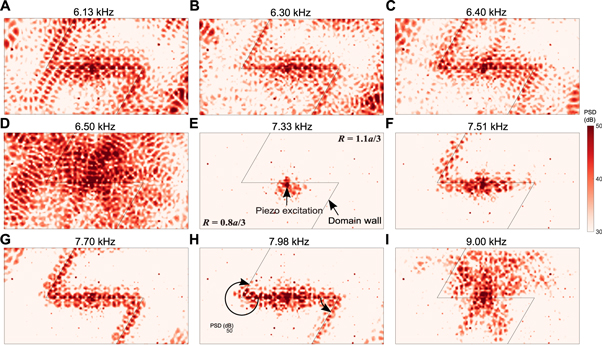
Figure 4. Experimentally obtained steady-state transmission maps at multiple excitation frequencies of the piezoelectric actuator located at the domain wall. Colors indicate the power spectral density calculated from the measured out-of-plane velocity of the plate. (A)–(C) Wave localization at the domain wall for the frequencies inside PBG. (D) and (E) Disappearance of this localization indicates the dispersion region between PBG and CBG, where no localized topological mode exists at the domain wall. (F)–(H) Emergence of wave localization at the domain wall once again indicates the region of CBG. (I) Wave transmission at a frequency above CBG.
Download figure:
Standard image High-resolution imageRemarkably, for the frequencies above this point, we again observe wave localization along the domain wall (figures 4(F)–(H)). This corresponds to the localization region in the CBG as indicated in figures 3(B), (C). We clearly observe a persistent wave localization along the horizontal domain wall for a wide range of frequencies. Among these, the transmission at 7.70 kHz (figure 4(G)) is robust, in which the wave follows the entire domain wall without any significant back-scattering around the sharp bends.
It is worth pointing out that at 7.51 and 7.98 kHz (figures 4(F) and (H)), the wave back-scatters around the sharp bends. A similar behavior was also observed recently in experiments on a mechanical counterpart of quantum valley Hall effect [35], where guided topological waves are back-scattered around a sharp bend for some frequencies inside the topological bandgap. However, here we observe that the wave is able to pass through the left bend at a lower frequency (figure 4(F)) and through the right bend at a higher frequency (figure 4(H)). This implies the preference of the topological wave propagation around one bend over the other, depending on the excitation frequency in the CBG. We explain this mechanism by the asymmetry of the two bends experienced by the spin waves. That is, as marked by the circular arrows in figure 4(H), the bending angle experienced by the counterclockwise spin that propagates towards the right is different from that by the clockwise spin towards the left. Note that in this symmetry-protected topological system, we have intentionally broken the C6 symmetry at the domain wall, including the sharp bends. This makes the modes less 'protected' (i.e. less robust), thereby resulting in the spin-dependent transmission efficiency around the bends (see the transient wave propagation in movie 3 for its further verification is available online at stacks.iop.org/NJP/20/113036/mmedia).
3.4. Robust waveguiding
Now we demonstrate robust waveguiding capabilities of our system by capturing the transient wavefield when excited at the frequencies inside PBG and CBG. Navigating the steady-state profiles observed in the previous section, we choose two central frequencies of excitation, 6.3 kHz (in PBG) and 7.7 kHz (in CBG), and send Gaussian pulses from the piezoelectric actuator. In figures 5(A)–(C), we show transient wave propagation on the plate at three different time steps inside PBG. We observe that the wave, emanating from the point of excitation at the middle of the domain wall, is effectively guided through the domain wall. Here, we verify that a counterclockwise spin propagates towards the right and a clockwise spin propagates towards the left (see movie 4 is available online at stacks.iop.org/NJP/20/113036/mmedia). Note in figure 5(C) that there is some visible leakage into the bulk, complying well with the result from the steady-state response (figure 4(B)). In figures 5(D)–(F), we show transient wave propagation inside CBG. It is evident that this wave is also being guided along the domain wall without any significant back-scattering at the sharp bends (see movie 5 is available online at stacks.iop.org/NJP/20/113036/mmedia). However, the key difference is that there is no evident leakage into the bulk due to the presence of CBG (figure 5(F)). This result is consistent with the supercell analysis (as shown in figure 3(B)) and the steady state response (figure 4(G)). In appendix C, we discuss a way to quantify the wave transmission efficiency in these two cases.
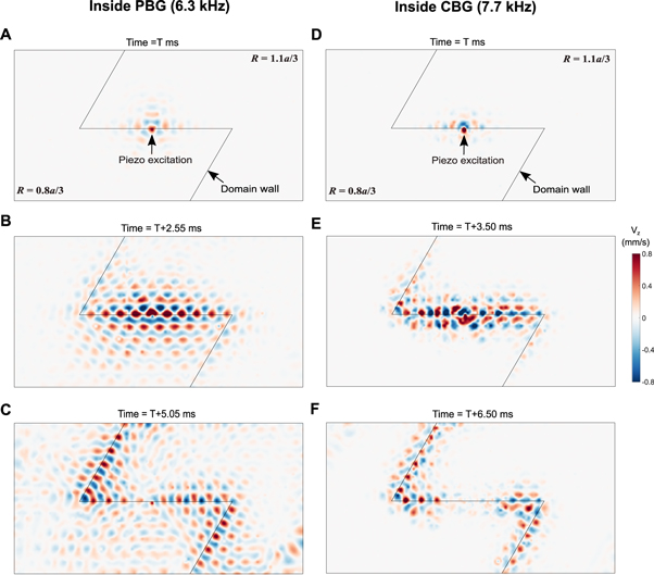
Figure 5. Experimentally obtained transient wavefields. (A)–(C) Velocity wavefields when a Gaussian input centered at 6.3 kHz is injected by the piezoelectric actuator in the middle of the domain wall. (D)–(F) Wavefields for the Gaussian input centered at 7.7 kHz.
Download figure:
Standard image High-resolution image4. Discussion
In this study, we have demonstrated numerically and experimentally the capability of topological waveguiding in a plate with local resonators. By incorporating the local resonance effects in the design, we observe some novel phenomena in this study. First, the low-frequency bending mode of the bolt leads to the creation of a pair of double Dirac cones, thus invoking topological effects at low-frequencies. Second, it enables us to deal with undesired in-plane plate modes, which makes it possible to clearly guide flexural waves along a topological waveguide, eliminating their leakage to in-plane modes. This is highly desirable in designing efficient waveguides for low-frequency flexural waves. In addition, we have also observed spin-dependent transmission efficiency of our topological waveguide around sharp corners for certain frequencies inside topological bandgaps. This is an interesting feature that can be exploited in applications, but at the same time, demands further exploration.
This simple and tunable design paves the way for a number of studies in future, especially with regard to studying the effect of disorder in such symmetry-protected topological systems. For example, the height of the bolts can be changed, or a nut can be attached to it, in order to introduce disorder in the system (see appendix D for a few examples). It is remarkable that even though a degree of disorder exists in the current setup in terms of bolt torques and plate threads, which in turn can change the effective coupling, we are still able to guide stress waves robustly. This is a hallmark of topological mechanical systems.
Acknowledgments
We gratefully acknowledge fruitful discussions with Krishanu Roychowdhury (Cornell University), Rui Zhu (Beijing Institute of Technology), and Panayotis Kevrekidis (University of Massachusetts, Amherst). We thank Hiromi Yasuda, Joshua Carter, Minh Nguyen, Sean Lay, and Dzung Tran from the University of Washington for their help in setting up the experiments. We are grateful for the support from NSF (CAREER-1553202 and EFRI-1741685).
Appendix A.: Geometrical details of the bolts
We model the bolts by assuming a uniform diameter along their shank and threaded areas as shown in figure A1. We take the height h of the bolt above the plate as 8.5 mm (measured nominal value), which is dictated by the length of the thread and the applied torque to the bolt during the assembly process.

Figure A1. Bolt geometry used for numerical simulations.
Download figure:
Standard image High-resolution imageAppendix B.: Modeling of the bolt-plate contact
We first model the bolt-plate contact using the simplest approach, i.e. assuming a rigid connection at the entire contact area between them (see figure B1(A)). The resulting dispersion is plotted in figures B1(B), (C) for the cases with R = 0.8a/3 and R = 1.1a/3, respectively. The colormap indicates the polarization of plate modes as discussed in the main text. Though we find the existence of topological bandgap, the dispersion bands are generally up-shifted in comparison to the experimental observations (see steady-state transmission in movie 2). This makes sense because by assuming this perfectly rigid connection, we overestimate the resulting out-of-plane stiffness that comes from the threaded contact between the bolt and the plate. Therefore it leads us to scale down the contact area as shown in figure B1(D). We introduce a tiny cut in the plate tcut = 0.15 mm, from the top and the bottom as shown, to separate some areas of the plate from the bolt, and therefore maintain an effective thickness  at the contact. In this way, the resulting dispersion bands (see figures B1(D)–(F)) explain the experimentally observed wave transmission to a reasonable degree. Note that a better match can be achieved if we model the thread connection between the bolt and plate with a greater detail. Nonetheless, our simple model with a reduced contact area captures the effective contact stiffness reasonably well, thus elucidating the nature of bandgaps and topological localization in our bolted plate system.
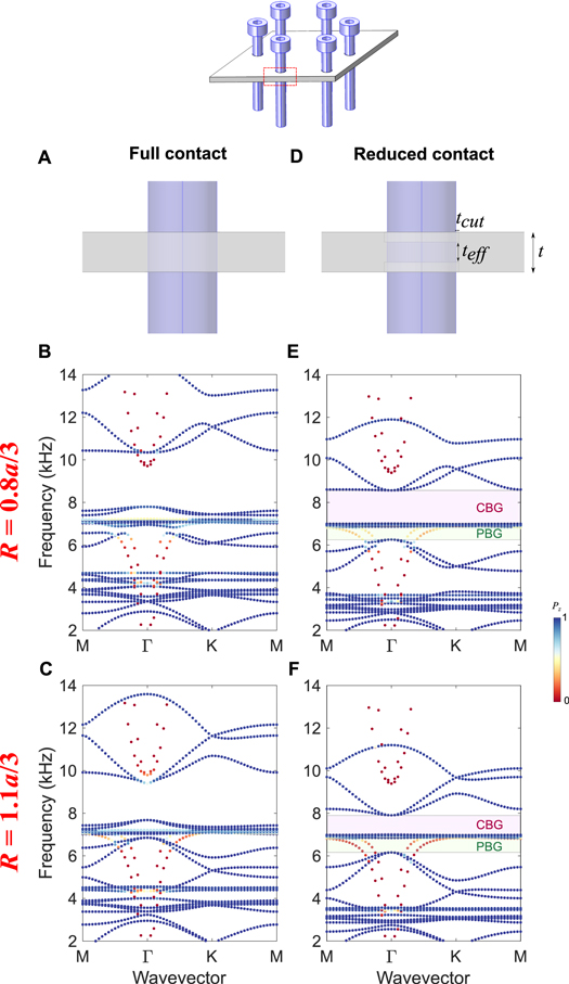
Figure B1. Scaling of dispersion curves. (A) The 'full contact' model, in which the plate and the bolt are rigidly connected throughout the entire contact area (whole thickness of the plate). (B) and (C) Dispersion curves for this model in configurations with  and
and  , respectively. (D) The 'reduced contact' model, in which the plate and the bolt are connected only through a limited area (a fraction of thickness of the plate). (E) and (F) The corresponding dispersion curves.
Download figure:
Standard image High-resolution imageAppendix C.: Wave transmission efficiency quantification
In this section, we show one of the ways to examine the efficiency of topological waveguiding. Our analysis is based on the postulation that while the wave is guided along the domain wall, one can treat it as a 1D wave. Therefore, we first extract velocity time-history of all the points along the domain wall for the transient results shown in figure 5. We then take only the maximum amplitudes in these time-history profiles and plot them along the 1D wave path in figure C1. We observe a high wave amplitude at the center of the path, which corresponds to the excitation point in the plate. The injected excitation pulse is then transmitted to both sides, the left and the right, along the domain wall. We observe a gradual decay of amplitude before the wave reaches the bends. This can be attributed to the dispersion of the Gaussian wave packet. Remarkably, this trend does not change drastically as the wave passes through the left and the right bends. This indicates an efficient wave transmission along the topological waveguide. However, one should be aware of the drawbacks of this method of calculating the transmission. First, it accounts for the wave energy reaching at the end of the domain wall (indicated as 'top' or 'bottom' in figure C1) directly from the center, without passing through the bends. As a result, the velocities extracted in figure C1 would not accurately represent the wave transmission solely through a topological waveguide. Also, this method produces a fluctuating profile of velocities, depending on the location of velocity measurements. This is consistent with the fact that we witness such spot-by-spot variations of velocity amplitudes in the transient response of the plate as seen in movies 4 and 5. Despite these drawbacks, the trends shown in figure C1 are evident enough to demonstrate the efficient wave transmission along the bent paths. We also note in passing that the authors' previous studies have numerically shown the clear distinctions between topological and trivial waveguiding using a uniform platform of dial-in topological metamaterials [17].
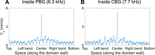
Figure C1. Quantification of wave transmission efficiency along the domain wall. (A) Maximum velocities attained at discrete points along the domain wall over time, for the case of PBG as shown in figures 5(A)–(C). Note that the x-axis describes the domain wall, highlighting the location of two bends and the center of the plate. (B) The same for the case of CBG as shown in figures 5(D)–(F).
Download figure:
Standard image High-resolution imageAppendix D.: Tuning dispersion by bolt height
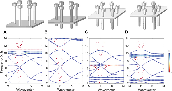
In this section, we show numerically some exemplary cases to tune the plate dispersion by changing the height h of the bolts. In figure D1, we show the dispersion curves for the case with R = a/3 for a number of bolt heights. We observe that the bolt height primarily influences the bending resonance of the bolts, and therefore affects the onset of the locally resonant bandgap for in-plane plate modes (in red). However, by closely looking in the vicinity of the double Dirac cone for out-of-plane plate modes (in blue), we notice a slight change in these modes as well. Our current setup with the bolt height as 8.5 mm (figure D1(C)) is particularly unique as it shows the locally resonant bandgap for in-plane modes and the double Dirac cones for out-of-plane plate modes in the similar frequency range. This facilitates the emergence of a complete bandgap for all the plate modes as shown in the main text. Moreover, the emergence of two separate double Dirac cones in the vicinity of bolt bending resonances is also remarkable. Therefore, we see that such a dependence of dispersion modes on the bolt height can be further utilized to tune the system.
Figure D1. Tuning dispersion by bolt height. (A)–(D) The configurations (R = a/3) with bolt height h = 27.5, 19.5, 8.5, and 5 mm, respectively.
Download figure:
Standard image High-resolution image