

Abstract
The shape memory behavior of smart materials is widely used for stimulation or shape-shifting purposes. Shape memory polymers (SMPs) can shape and force recoveries accompanied by attractive attributes such as biocompatibility, biodegradability, and universality. In this paper, a thermoplastic elastomer (TPE) is used as a complementary material for 4D printed polylactic acid (PLA) structures to enhance their shape and force recovery properties and lower the stimulation temperature for more practical implementations. Two approaches are followed to provide SMP composites (SMPCs): multi-layered and multi-material lattices. In multi-layered lattices, specimens are comprised of separate layers and different ratios of SMP and TPE materials. For comparison, PLA-TPE filaments with the same ratios of multi-layered lattices are produced and used to fabricate multi-material lattices. Dynamic mechanical thermal analysis tests showed a reduction in the glass transition temperature of the manufactured PLA-TPE filament. X-ray diffraction test was conducted to prove that the crystallinity of the developed PLA-TPE material increases which explains the better shape memory effect in the multi-material specimens. Phase separation occurred in low ratios of TPE in PLA, discernible in field emission scanning electron microscope (FESEM) images, resultting in low quality in one of the developed PLA-TPE filaments. FESEM images also showed proper miscibility of TPE in PLA in higher ratios. Thermomechanical tests were done on printed specimens to examine and compare the shape and force recovery of the produced SMPCs. While the shape recovery of multi-material samples was not as good as multi-layered samples, both approaches have better shape recovery results than the PLA sample. Due to a lower glass transition temperature in multi-material lattices, their shape recovery process started at lower temperatures widening their potential practical applications. Force recovery of multi-material samples revealed a significant improvement which was due to more oriented crystalline polymer structures.
Export citation and abstract BibTeX RIS
1. Introduction
Smart materials are a new type of materials that can perceive and respond to their environmental condition. More specifically, smart materials can be defined as those that can remember configurations and repossess such configurations by a proper stimulation. This property of smart materials has attracted researchers in various fields such as automotive [1], aerospace [2], textile [3], robotics [4], and medical [5] industries.
The shape memory polymers (SMPs) are a division of smart materials capable of remembering their previous shape. When these materials are heated to a temperature higher than the glass transition temperature (Tg), polymeric chains of the material get weaker and can easily slide on each other. Therefore, by applying a small force, the material can be deformed to the desired shape. In practical applications, by cooling the material down to temperatures lower than Tg, the temporary shape is maintained, and by heating the material to temperatures higher than Tg, the material automatically restores its permanent shape. SMPs with different glass transition temperatures are available [6, 7].
4D printing is a fabrication process for active materials deformed by different stimulations such as changes in temperature, humidity, electromagnetic field, and light [8–10]. Primarily introduced 4D printing in 2013 at the TED conference [11]. Hydrogels [12, 13] and SMPs [14, 15] are the primary materials used for 4D printing. Non-swelling polymer or filament are used in the production of hydrogels using 4D printing. The hydrogel swells up when the printed structure is submerged in a solvent, leading to the specimen's deformation [16, 17]. Hydrogels do not require postproduction programming, which is their advantage over one-way SMPs. However, there are three critical issues with hydrogels. First, hydrogels are soft materials and the corresponding printed structures do not usually have the stiffness or strength required in some applications. Second, gels have a low deformation speed when programmed to swell, especially in large deformations. Third, the activated swollen shape is unstable. In other words, smart materials based on hydrogel are susceptible to environmental conditions, and hence obtaining a programmed shape requires strict control of the environmental conditions which is not always feasible [18]. While SMPs do not have the mentioned problems, due to their intrinsic advantages over hydrogels, researchers have strived to improve the shape memory effect (SME) of SMPs in recent years [19, 20].
To improve the shape memory and structural behavior of these materials, various factors such as constituent material [21–23], macro-molecular details [24, 25], and structural and geometrical design can be considered [6, 26, 27]. The effect of different material layout in a multi-material composite (SMP and elastomer) on shape memory performances are investigated by Yuan et al [28], where they studied two different layout patterns to examine the effect of volume fractions on the shape fixity of the composite. The effect of raster angle as a 3D printing parameter on the actuating performance of bilayer polylactic acid (PLA)/paper composites is studied for soft robotics applications [29]. In another research, a bilayer composite is produced by attaching one layer of elastomer to one layer of stretched SMP. The orientation and elongation of the stretched SMP layer can determine the achieved program shape of the bilayer composite [30]. In theoretical aspects, a constitutive model can be developed to predict the shape memory behavior and active bending behavior of SMP-elastomer bilayer composites [31].
Fifty to seventy percent of the registered patents in the SMPs field are related to the biomedical area [32]. Thus, it makes a suitable material for application in the medical field [33]. PLA is an SMP [26] with good biocompatibility and controllable biodegradability [34, 35] In our previous research [26], the effect of geometrical design on the thermomechanical behavior of SMPs was investigated experimentally. The thermomechanical tests demonstrated that the lattice plates with rounded rectangle unit cells had the highest shape and force recovery compared to their applied pre-force [26]. It can be concluded that PLA has deficiencies such as a high stress relaxation in short time, low force and shape recovery ratio, and high  which is not desirable for biomedical applications.
In previous studies, the effect of different volumetric ratios of SMP and elastomer in multi-layered and multi-material structures on SME of SMP composites (SMPCs) is not investigated. In addition, implementing a lattice structure in specimen design is an alternate way to improve the SME of specimens [26]. This research aims to improve the SME of PLA by following two approaches: producing multi-layered (M-L) and multi-material (M-M) PLA-thermoplastic elastomer (TPE), as shown in the graphical abstract of the paper in figure 1. TPE is used as an additive material to enhance the shape memory behavior of lattice plates with rounded rectangle unit cells. Multi-layered and multi-material PLA-TPE lattice plates with different thicknesses and volumetric ratios are produced using the 4D printing method, respectively. Then, to characterize the produced materials, three tests of dynamic mechanical thermal analysis (DMTA), X-ray diffraction (XRD), and field emission scanning electron microscope (FESEM) are performed. The thermo-mechanical tests are done on both the multi-layered and multi-material SMPC lattice plates to study the results of these two approaches on the SME of PLA-based specimens.
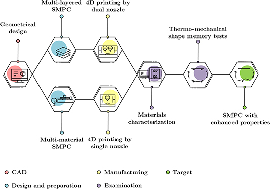
Figure 1. Graphical abstract of the present research.
Download figure:
Standard image High-resolution image2. Materials and methods
According to our previous research [26], the rounded rectangle lattice topology has a higher shape recovery and force recovery capability the required programming pre-force compared to hexagonal honeycomb and diamond lattices. Therefore, the rounded rectangle lattice structure is chosen as the base geometry for all specimens in this research. Due to the dimensional restrictions of the thermomechanical test equipment, dimensions of  were considered for all the lattice plates. Two approaches for the multi-material additive manufacturing are considered. In the first approach, multi-layered lattice plates are produced employing a dual-nozzle printer. In the second approach, multi-material filaments are fabricated and implemented to print the lattice plates a single-nozzle printer.
2.1. Multi-layered lattice plates
2.1.1. Design and theory.
As shown in figure 2(a), a multi-layered SMPC consists of two SMP layers on the sides and an elastomer layer in the middle. The governing equilibrium equation for a programmed composite is
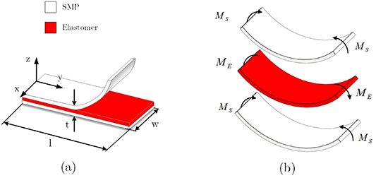
Figure 2. (a) A three-layer SMPC programmed for flexure. (b) Induced moments in the multi-layered SMPC after bending.
Download figure:
Standard image High-resolution imagewhere  is the stress in the axial direction, and
  and
and  are the stripe thickness and width, respectively. We aim to program a three-layer flat composite to have a curved shape, when programmed (i.e. in its temporary state). When the composite is programmed (figure 2(b)), two SMP layers maintain their programmed shape, while the elastomer layer tends to repossess its original shape. In the programmed state of SMPC, there is a static equilibrium in the structure. Therefore:

where  is the moment exerted on the elastomer layer by the SMP layers and
  is the moment applied on each SMP layer by the elastomer.
2.1.2. Production of lattice plates.
PLA and PLA-TPE lattice structures (M-L) with PLA to TPE thickness ratios of 5:1, 4:2, and 3:3 were produced by fused deposition modeling (FDM) AM machine INDU (TOP 3DP, Iran). To investigate the effect of the layered structure of lattices on shape and force recovery, a two-layered PLA lattice with equal ratios (M-L PLA 3:3) is produced and glued together to be compared to the PLA lattice. The reason behind using the FDM method is its straightforward functioning, low production time, and low cost. On the other hand, employing innovative materials [36, 37] and reinforced composites [38, 39] was noticed with FDM 3D printers in recent years. Since initial printing conditions can affect the mechanical properties and shape memory behavior of SMPC, all specimens are printed under identical conditions. The parameters used for 3D printing multi-layered specimens are presented in table 1. The TPE layer is in the middle part of all the multi-layered structures, and PLA is placed symmetrically on its sides (figure 3(a)).
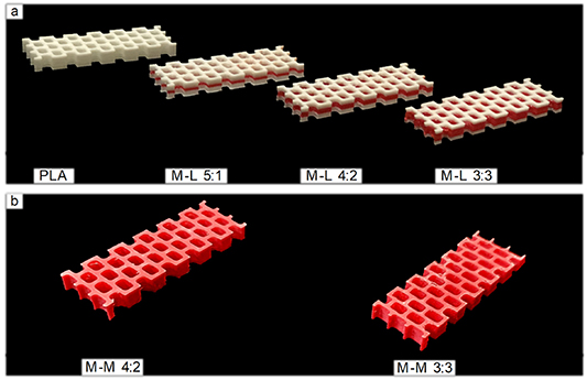
Figure 3. (a) PLA and multi-layered PLA-TPE specimens with PLA to TPE volumetric ratios of 5:1, 4:2, and 3:3; (b) multi-material PLA-TPE specimens with PLA to TPE volumetric ratio of 4:2 and 3:3.
Download figure:
Standard image High-resolution imageTable 1. Summary of 3D printer configurations used for manufacturing the lattice plates.
| Printer setting | Value | Printer setting | Value |
|---|---|---|---|
| Layer height | 0.2 mm | TPE nozzle temperature | 240 °C |
| Shell thickness | 0.4 mm | PLA-TPE nozzle temperature | 200 °C |
| Fill density | 100% | Print-bed temperature | 50 °C |
| Print speed | 20 mm s−1 | PLA filament diameter | 1.75 mm |
| PLA nozzle size | 0.4 mm | TPE filament diameter | 1.75 mm |
| TPE nozzle size | 0.4 mm | PLA-TPE filament diameter | 1.75  0.1 mm 0.1 mm |
| PLA nozzle temperature | 200 °C |
2.2. Multi-material lattice plates
2.2.1. Design and theory.
From a microscopic point of view, thermoplastic materials like PLA have a disoriented molecular structure which makes them amorphous. Alternatively, elastomeric materials such as TPE usually have an oriented molecular structure that can potentially be exploited to improve the crystallinity of thermoplastic materials, as schematically demonstrated in figure 4. This increase in crystallinity would enhance SME in the resulting material. The length of polymeric chains in amorphous materials is shorter than crystalline materials, making amorphous polymers more vulnerable to damage during deformations compared to crystalline polymers. Blending a crystalline polymer with an amorphous polymer will lower damage to the chains under large deformations. Thus, SMP and elastomer blending enable us to tune the SME of the mixture [40].
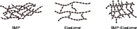
Figure 4. Schematic of the molecular structure of thermoplastic SMP, elastomer, and SMP-elastomer.
Download figure:
Standard image High-resolution image2.2.2. Production of multi-material SMPC filaments.
Several multi-material filaments composed of different volumetric ratios of PLA and FLEX TPE (YouSu, China) were produced. First, PLA and TPE filaments with PLA to TPE volumetric ratios of 5:1, 4:2, and 3:3 are chosen and shredded using a pelletizing machine. A mixing machine (Brabender, Germany) is used to merge filaments at 200 °C in 5 min. The mixing machine measures and displays the instantaneous torque resistance of the material. When the measured torque becomes stable, it implies that the mixture has become homogenous (figure 5(a)). Then, after being blended employing a hot press machine, the materials are formed into thin sheets (figure 5(b)). Using the hot press machine, the materials are heated up to 200 °C and pressurized up to 90 bar. In the end, materials are transformed into granules for the filament production process (figure 5(c)).
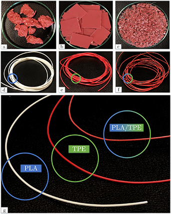
Figure 5. (a) PLA-TPE after mixing, (b) PLA-TPE plates made by hot pressing, (c) PLA-TPE granules, (d) commercial YouSu PLA filament, (e) commercial YouSu TPE filament, (f) PLA-TPE-based filament, and (g) close-up image of the filaments.
Download figure:
Standard image High-resolution imageProducing filament with the desired quality, diameter, and extrudability has always been challenging [41]. This research, produces filaments with decent quality using an extruder developed by the School of Mechanical Engineering of the University of Tehran (figure 5(d)). First, the temperature of the extruder nozzle should be set to an appropriate level to result in a consistent filament diameter. To this end, we use a trial-and-error approach for the extruder temperature in the temperature interval of 160 °C–230 °C. Afterward, PLA-TPE granules are added to the hopper. The motor's rotational speed is set to 35 rpm. After leaving the nozzle, the extruded filaments are cooled down using a fan. By this method, filaments made of PLA-TPE with volumetric ratios of 4:2 and 3:3 are produced at the extruder temperature intervals of 180 °C–190 °C and 190 °C–200 °C, respectively. However, no optimal extruder temperature could produce 5:1 volumetric ratio PLA-TPE filaments with a consistent diameter. FESEM images in the section 3.2 further investigate this phenomenon.
2.2.3. Production of lattice plates.
PLA-TPE structures (with PLA to TPE material volumetric ratios of 4:2, and 3:3) are produced by the same 3D printer used for the multi-layered specimens. Since configurations of the additive manufacturing method significantly affect the SME, configurations of the 3D printer for the manufactured multi-material lattice structures (M-M) are set identical to those in the multi-layered specimens described in the previous section (table 1). The structure with rounded rectangular unit-cells is fabricated with the desired quality, as one may observe from figure 3(b).
2.3. DMTA tests
To measure  of each material, DMTA was performed. The results are essential for thermomechanical shape memory tests which are essential for calibrating smart materials constitutive models. DMTA is carried out by applying a fluctuating sinusoidal load with a frequency of
  on each specimen. Various properties such as storage modules (
 ), loss modules (
 ), tan(
 ), and glass transition temperature (
 ) are obtained by this method. The glass transition temperature was obtained by
  onset method [42]. To obtain the
  of the PLA filaments as well as the fabricated PLA-TPE filaments with different volumetric ratios, DMTA is performed in the temperature intervals of
  °C to
°C to  °C and
  °C to
°C to  °C, respectively. It is expected that adding TPE decrease
  of the resulting material. Therefore, the temperature interval for the fabricated PLA-TPE specimens is chosen to be in a broader range.
2.4. Thermo-mechanical shape memory tests
In this section, conditions of three-point bending are discussed. Figure 6 demonstrates a schematic of complete shape recovery and force recovery processes in a three-point bending test [26]. The SANTAM device measured the required force for a specific displacement for each specimen. To obtain the shape and force recovery, specimens are placed in respectively unconstrained and constrained configurations to measure the displacement and force due to shape and force recovery. For programming of the specimens, a displacement of 4.5 mm
5
(which leads to 10% principal strain in the bulk material) was applied on all of them at the programming temperature ( ). Liquid water is used to control the temperature throughout tests. The advantage of using water in thermomechanical tests is that the temperature of water propagates to all the regions of the specimen uniformly, and thus, the specimen possesses an isothermal condition.
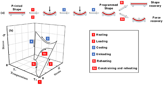
Figure 6. (a) The schematic of the shape and force recovery process in three-point bending mode. (b) A 3D diagram of the shape memory cycle.
Download figure:
Standard image High-resolution imageThe thermomechanical shape recovery test in three-point bending mode for SMPCs is schematically shown in figure 6(a). As mentioned in section 3, water is used for the thermomechanical tests and the temperature is controlled by hot- and cold-water flows. Each specimen is placed separately in a vessel containing room-temperature water and then heated to a higher temperature of  (step 1). A displacement of 4.5 mm is applied to the specimen using a pin attached to the load cell at the higher temperature (step 2). Then, a cold-water flow is fed to the vessel by a pump, and a drain pump depletes the hot water (step 3). After cooling the vessel, the specimen maintains its programmed shape, after which the pin is removed from the loading point (step 4). The specimen may demonstrate an insignificant elastic strain. In the last step for the shape recovery, the water temperature is arisen to
  and the specimen recovers its initial state (step 5i). Alternatively, in the force recovery case, the load cell pin is placed at the middle of the specimen to restrain its shape recovery. The force exerted by the specimen, is measured during its recovery process triggered by reheating to
  (step 5ii). Force recovery ratio is defined by the ratio of the maximum force recovery to the pre-force spent on the programming of the specimen.
Equation (3) is used to calculate the shape recovery ratio in the shape memory cycle [41]. In this equation, the applied deflection of the beam is 4.5 mm and  is the unrecovered portion of the specimen deflection at 64 °C
It should be noted that microscopic camera and image processing techniques are used to measure the beam deflection shape recovery of the specimens.
3. Results and discussions
In this section, first, the results of three characterization tests (DMTA, FESEM, and XRD) are reported to examine the properties of the manufactured materials. Afterward, the shape memory behavior of pure PLA and PLA-TPE specimens fabricated as multi-layered and multi-material SMPC are studied in terms of shape and force recovery.
3.1. DMTA
In this research, storage modules ( ) versus temperature diagrams are used to measure the glass transition temperature
  . For PLA it was found to be
  (figure 7(a)). In developing multi-material specimens,
  was decreased around
  (figure 7(b)) by adding a minor fraction of TPE to PLA (1:5 ratio). Further increase in the TPE volume fraction resulted in an only minor reduction of
  , as depicted in figure 7(c). Ultimately, adding more TPE to PLA resulting in equal volumetric ratios, lowered
  about
about  as compared to pure PLA (figure 7(d)). The reduction of
  is a significant improvement in SMPC characteristics which can potentially increase their usage in many applications particularly in biomedical applications.
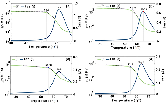
Figure 7. Diagram of E' and tan(δ) versus temperature for (a) PLA, and multi-material PLA-TPE with volumetric ratio of (b) 5:1, (c) 4:2, and (d) 3:3.
Download figure:
Standard image High-resolution image3.2. FESEM
In the material design stage, FESEM images of the developed materials are utilized to examine the effect of the volumetric ratio on the miscibility of PLA-TPE in filament form. The three multi-material filament specimens with different volumetric ratios of PLA-TPE were initially cooled down in liquid nitrogen to provide the possibility of a brittle fracture. FESEM images of the fractured cross-sections of the filament specimens are presented in four scales in figure 8. Higher TPE fractions have led to a better mixture between two constituents, forcing PLA polymeric chains to adapt TPE molecular structures. Hence, porosity and voids of the multi-material specimens have been decreased in higher levels of TPE fraction. On the other hand, as a thermoplastic material, PLA tends to develop more voids when heated, which is abundant in the fabricated M-M 5:1 filament. As one may observe from figure 8, the M-M 5:1 mixture has led to dissatisfaction and, therefore, varying filament diameter due to the phase separation at low TPE fraction. Thus, M-M 5:1 is not considered in the following tests.
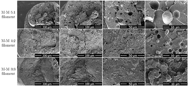
Figure 8. FESEM images of multi-material filament specimens with different volumetric ratios of PLA-TPE in four different scales.
Download figure:
Standard image High-resolution image3.3. XRD test
XRD analysis is based on x-ray beams and Bragg's law which is usually utilized to study materials with crystalline structures [43]. Since the diffracted spectrum of each produced material is unique, XRD is utilized to study the crystallinity of the specimens. Figure 9 shows the XRD result of four PLA, TPE, M-M 4:2 and 3:3 specimens. Due to the phase separation in M-M 5:1 and varying filament diameter, an XRD test was not conducted for this ratio. As illustrated in figures 9(a) and (b), PLA is amorphous due to the low and mild peak in the spectrum, while TPE has an intense peak with a large magnitude which means it can be considered a crystalline material. Figure 9(c) shows an intense peak in M-M 4:2 meaning it must have a highly crystalline structure. By adding more TPE to the mixture to obtain M-M 3:3, the crystallinity of the PLA-TPE specimen is decreased, as demonstrated in figure 9(d). In other words, adding TPE to PLA in lower ratios can highly increase the crystallinity of the mixture, while higher ratios of TPE disorient the molecular structures resulting in less crystallinity in the mixture.
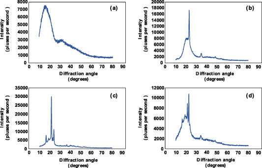
Figure 9. XRD spectrum for four different specimens of (a) PLA, (b) TPE, (c) M-M 4:2, and (d) M-M 3:3.
Download figure:
Standard image High-resolution image3.4. Shape recovery
Reheating during the shape recovery process in the three-point bending test (step 5i in figure 6) is shown for the specimens in figure 10. In the PLA and multi-layered lattice cases, the temperature has been raised to  (
( of PLA). Since reducing the programming temperatures broadens the range of applications of an SMPC material, a lower programming temperature of
  (close to their
  ) was considered for the multi-material specimens. This can justify our purpose of expanding the applications of SMPs in different areas, as discussed in section 4.4. In addition, PLA has an amorphous structure which makes it vulnerable to damage at
  , therefore, the programming step for PLA and multi-layered specimens cannot be carried out in lower temperatures.

Figure 10. The shape recovery process of PLA, multi-layered, and multi-material PLA-TPE lattice plates.
Download figure:
Standard image High-resolution imageShape recovery versus temperature diagrams are presented in figure 11, revealing that the PLA lattice has the lowest shape recovery extent. Furthermore, the layered structure of PLA lattice does not affect much the shape recovery of the samples. As depicted in figure 11(a), the slope of the multi-layered specimens during the shape recovery process is higher than those in the PLA and multi-material lattices. In other words, the shape recovery speed of the multi-material specimens is slower than that of the multi-layered specimens. Technically, the recovery process of multi-material specimens is started in lower temperatures compared to multi-layered specimens. This does not mean that multi-material specimens have a faster shape recovery, since the recovery speed is the slope of the recovery curve. As shown in figure 11(a), the slope of multi-layered specimens is larger than the slope of multi-material counterparts. From a macroscopic point of view, the multi-material specimens are composed of a single material of PLA-TPE, while multi-layered specimens are comprised of two different materials of PLA and TPE. Therefore, the elastic characteristic of TPE in multi-layered specimens expedites the recovery process and enhances the maximum shape recovery, once the PLA phase transforms from glassy to rubbery.
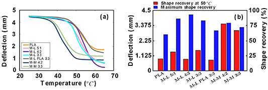
Figure 11. (a) The diagram of deflection versus temperature for PLA and PLA-TPE multi-material and multi-layered lattice plates during the shape recovery. (b) The shape recovery ratio at  °C and
  °C.
°C.
Download figure:
Standard image High-resolution imageNote that the reported values in figure 11(b) are obtained by calculating the shape recovery ratio (i.e.  in equation (3)) at both
  and
and  for each specimen. In other words, even though
  for multi-material specimens is lower than that in PLA and multi-layered specimens, the shape recovery process of multi-material specimens is also reported for temperatures up to
  . As speculated in section 2, the addition of elastomer material (TPE) has enhanced the SME of SMPs. In general, the thermomechanical test results (figure 11) unveil that the shape recovery of multi-layered and multi-material lattice plates has remarkable improvements compared to the pure PLA lattice.
The shape recovery of PLA and the multi-layered lattices started at  , while the shape recovery process in multi-material specimens started at lower temperatures (i.e. ∼
 ) (figure 11). Among multi-layered specimens, the maximum shape recovery belonged to M-L 4:2 lattice, while the maximum shape recovery in multi-material specimens was recorded in M-M 4:2 case (figure 11(b)). The multi-material lattices were almost fully recovered at
  , while at that temperature, PLA and multi-layered lattices were just about to start their recovery process. As expected, raising the temperature of the multi-material specimens to
  did not changed their shape recovery response. This expedition in recovery process of multi-material lattices can potentially make the PLA-TPE specimens more beneficial to practical applications. As discussed in XRD test results, M-M 4:2 has a higher crystallinity and thus longer polymeric chains and more oriented micro-molecular structures than M-M 3:3, which results in a more significant shape recovery for M-M 4:2.
3.5. Force recovery
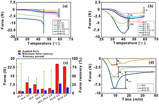
The results of force recovery in constrained thermomechanical tests are illustrated in figure 12. Figure 12(a) plots the maximum force recorded for PLA and multi-layered specimens at  and for the multi-material specimens at
  . The cooling step was performed after applying the required displacement at the designated temperatures, which led to a zero force for PLA and multi-layered specimens. However, the measured force after the cooling step for the multi-material specimens did not approach zero as the increased crystallinity in the specimens had enhanced their stiffness.
Figure 12. The force-temperature diagram in three-point bending test; (a) cooling step; (b) reheating step; (c) applied force and maximum recovered force; (d) relaxation of PLA and M-M specimens. RI, RII, and RIII are relaxation values for PLA, M-M 4:2, and M-M 3:3 specimens, respectively.
Download figure:
Standard image High-resolution image
The peaks in figure 12(b) show each specimen's maximum force recovery value during the reheating step. At the beginning of this process (up to  ), the force recovery value is negligible. By further increasing the temperature, the force recovery of PLA and multi-layered lattices started at a temperature interval of
  −
− . On the other hand, the force recovery process for the multi-material specimens started from the very beginning of the reheating process. The force recovery speeds of the multi-material specimens are higher than those of PLA and multi-layered specimens. This is because the temperature interval for the force recovery process of multi-material specimens is smaller than that of PLA and multi-layered specimens. It should be noted that the structure of the M-L PLA compared to pure PLA, has some constraints due to the printing process occurring between layers which makes the structure have a higher stored energy and therefore have a higher recovered force.
As shown in figure 12(c), the maximum force recovery in the multi-material lattices is much greater than in PLA and multi-layered lattices due to the increased crystallinity of multi-material specimens. The recovery ratio for the PLA specimen was the highest recorded one, while the multi-material specimens had the lowest recovery ratio (figure 12(c)). It should be noted that, in many applications, the magnitude of pre-force in the programming stage is not considered as a limiting factor. Under this consideration, the maximum force recovery of multi-material specimens is the highest recorded value.
Dashed-black contours indicate the relaxation step of PLA and multi-material specimens in figure 12(b), and it is elaborated with a force-time diagram in figure 12(d). Relaxation is calculated from the maximum force to the final force in the force-time diagram, shown in figure 12(d). The final force exerted by the PLA specimen approached zero, while this value for multi-material specimens approached non-zero values (about 2.5 N for M-M 4:2 and 4 N for M-M 3:3), which are desirable in many applications.
3.6. Potential application areas
SMPs have various applications in self-shape-shifting structures which their performance can be improved by higher shape and force recovery. For instance, self-folding origami structures can provide a remote and automatic assembly to minimize cost, time, and packaging efforts compared to conventional machining methods. For this purpose, self-folding SMP hinges and heating circuits are developed to generate the required torque for rotating hinges which can be used to self-assemble an origami-based robot [44, 45]. Self-folding structures can be built as a composite consisting of SMPsactivated by uniform heating [46]. These self-folding mechanisms can have applications in micro-scaled systems for various purposes such as antennas [47] and machine assembly [48]. Shape-shifting behavior can be manipulated by implementing a hyperelastic layer in bi- or multi-layered SMP strips, which yield self-twisting/self-rolling or self-folding origami structures [49].
4. Conclusions
In this paper, TPE was used to enhance the SME of PLA and decrease its glass transition temperature. Two approaches were followed to evaluate PLA-TPE SMPCs: multi-layered and multi-material lattice plates.
Multi-layered lattices were composed of distinct layers of PLA and TPE with different volumetric ratios, 3D printed using a dual-nozzle printer. Due to the elastic behavior of TPE, multi-layered lattices showed promising results in terms of shape recovery and an enhancement in force recovery. The glass transition temperature of multi-layered specimens could not be reduced as its glass transition temperature solely depended on the PLA material. No delamination was observed during the thermomechanical tests carried out at high temperatures.
For the multi-material lattices, PLA-TPE filaments with different ratios were fabricated and used. Due to phase separation observed in FESEM images, low ratios of TPE in PLA led to unsatisfactory filament quality. Multi-material specimens with proper PLA-TPE filaments were fabricated using a single-nozzle 3D printer. Thermomechanical tests showed an improved shape recovery compared to PLA specimens. However, the multi-layered lattice plates had the best shape recovery. The force recovery of multi-material lattices was better than pure PLA and multi-layered lattices. Multi-material lattices released their maximum recovered force at lower temperatures. In contrast to PLA, multi-material specimens kept a constant exerted force after their relaxation phase.
DMTA test conducted on PLA and PLA-TPE filaments revealed that the glass transition temperature of the developed PLA-TPE material was remarkably lower than PLA. XRD tests confirmed that the crystallinity of PLA-TPE material is superior to that in PLA and TPE in some ratios, which led to better SME in the fabricated lattices.
In future works, the developed materials can be implemented in biomedical applications (in-vivo and in-vitro tests) to experiment with the practical usage of enhanced SMPs. By obtaining thermo-visco-hyperelastic parameters of the evaluated SMPCs, numerical simulations can also be performed to predict their behavior in various conditions.
Data availability statement
All data that support the findings of this study are included within the article (and any supplementary files).
Footnotes
- 5
In our previous research [24], it was shown that for the rounded rectangle lattice plate with similar dimensions, a 4.5 mm deflection gives the maximum force recovery compared to its applied pre-force.