

Abstract
To address the flammable and chemical unstable problems of liquid electrolyte, the solid electrolyte is a promising candidate to replace liquid electrolyte for solid-state batteries. Herein, a composite polymer electrolyte (CPE) of 3D polyimide (PI)-nanofiber membrane-incorporated polyethylene oxide (PEO)/lithium bis (triflu-romethanesulphonyl) imid (LiTFSI) is reported. Three advantages of the PI nanofiber network in the CPE include providing a continuous, rapid transport channel of lithium ions to improve the Li-ion conductivity, improving the mechanical properties and stability, and effectively inhibiting the dendrite growth of Li metal. The PI/PEO/LiTFSI CPE delivers an ionic conductivity of 4.2 × 10⁻⁴ S cm−1 at 60 °C, a wider electrochemical window to 5.4 V, and an excellent thermal stability, which result in the excellent electrochemical performance of LiFePO4 full cells assembled with PI/PEO/LiTFSI CPE.
Export citation and abstract BibTeX RIS
1. Introduction
Lithium-ion batteries have been widely applied from electronic devices [1, 2] to the power grid [3]. High capacity, good cycling stability, and high security are three important factors for lithium-ion batteries [4]. The ever-increasing demand for the higher energy density of lithium batteries makes lithium metal anode come back to our sight [5, 6]. However, the lithium metal batteries using liquid electrolyte face several problems. Typically, the formation of Li dendrites leads to battery short circuit and safety risks [7]. Besides, the continuous consumption of electrolyte during cycling increases the resistance and reduces the cycle performance of the batteries [8]. Solid-state electrolytes [9] are expected to replace liquid electrolytes as a new generation electrolyte due to their high security, good stability, wide electrochemical window and high energy density [10]. Solid-state electrolytes can be divided into three categories: inorganic solid electrolytes [11], solid polymer electrolytes (SPEs) [12, 13] and their hybrids [14, 15]. Inorganic solid electrolytes [16] display high ionic conductivities and excellent mechanical and chemical stability. However, the inorganic solid electrolytes still suffer from many issues that hinder their application in solid-state batteries, including the rigidity nature and large interfacial impedance. SPEs have the advantages of good flexibility, high processability, and lightweight, so they are very promising as solid-state electrolytes [17, 18]. However low ionic conductivity and poor cycling stability caused by their soft nature limit the application of SPEs. Thus, the improvement of the ionic conductivity and the mechanical strength of polymer electrolytes is urgent to be addressed [19]. Composite polymer electrolytes (CPEs) [20, 21] that combine the advantages of both inorganic and pure polymer electrolytes are considered as promising candidates.
Adding fillers to polymer is a common method for the CPEs, which can improve the ionic conductivity and mechanical strength without sacrificing the flexibility of the electrolyte [22]. The addition of nanofillers increases the surface area of the amorphous region to form more pathways in the interface between polymer and fillers and improve the conductivity of lithium ions [23]. The fillers mainly include active-particle fillers (e.g. Li7La3Zr2O12 [24], NASICON-type LAGP/LATP [25] etc), passive-particles fillers (e.g. graphene oxide, TiO2 [26], metal-organic frameworks) and nanowires [27]. However, the nanowires or nanoparticles are easy to agglomerate in the polymer matrix, which reduces the electrochemical performance of the electrolytes [28]. The 3D-network structure of nanowires/nanofibers [29] with a continuous long-range lithium transport path can effectively avoid the agglomeration of fillers and improve the ionic conductivity of electrolytes [30, 31].
The most representative composite solid electrolyte is the PEO based system. Compared with many polymer matrix, PEO has many advantages, for example, Polyacrylonitrile (PAN) has poor ion conductivity and poor stability to Li metal, while PEO has good chemical stability and good stability to Li metal; Polymethyl Methacrylate (PMMA) film is hard and brittle, mechanical strength is poor, while PEO has good flexibility. Based on the above advantages, PEO has become a widely used polymer matrix. In addition to the polymer matrix, lithium salt also has a certain effect on the properties of the electrolyte. In recent years, due to the low ionic conductivity of organic lithium salts containing sulfonate anions, LiTFSI with larger anionic radii has been widely used. LiTFSI can promote the ion pair dissociation and improve the lithium ion conductivity of electrolytes. Gong et al [32] prepared a new solid-state electrolyte for 3D ceramic textiles based on PEO/LiTFSI, which showed excellent battery capacity. The electrolyte performance can be changed by changing the content of Li salt in the PEO matrix, Wu et al [33] designed lithium salts based on lithium bis(trifluoromethylsulfonyl)imide (LiTFSI) for poly(ethylene oxide) (PEO) to obtain a rubbery 'polymer-in-salt' solid electrolyte, emphasizing the importance of lithium salt design.
In this work, we proposed a type of polymer-polymer solid-state electrolyte (PI/PEO/LiTFSI) with good mechanical and electrochemical properties. The PI nanofiber membrane [5, 34] was demonstrated to improve the ionic conductivity, thermal stability, and mechanical properties of PEO/LiTFSI solid polymer electrolyte [35]. Figure 1 shows the preparation process of the PI/PEO/LiTFSI. Initially, the PI nanofiber membrane composed of interconnected nanofibers is prepared by electrospinning. Then, the PEO/LiTFSI solution is poured into the gap of the nanofiber network to form a CPE. The PI/PEO/LiTFSI shows good mechanical properties, high conductivity (4.2 × 10⁻⁴ S cm−1), wide electrochemical window, and good cycle performance in Li∣LiFePO4 batteries.
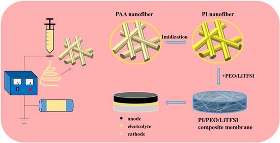
Figure 1. Synthesis process for PI/PEO/LiTFSI composite polymer electrolyte.
Download figure:
Standard image High-resolution image2. Experimental
2.1. Materials
Polyethylene oxide (PEO, MW = 600 000) was purchased from MACLIN reagent. Lithium bis (trifluromethanesulphonyl) imid (LiTFSI, 99%) was purchased from Aladdin. Acetonitrile (99.9%) was purchased from Beijing Inno Chem Science & Technology Co. Ltd Dimethylacetamide (DMAC, 99.9%) was purchased from Sinopharm Chemical Reagent Co. Ltd 1,2,4,5-Benzenetetracarboxylic anhydride (PMDA, ≥99%) and 4,4'-oxybisbenzenamine (ODA, ≥98%) were purchased from Aladdin. Polyimide (PI) nanoparticle was purchased from Dongguan Zhanyang Polymer Materials Co., Ltd PEO was dried under vacuum at 60 °C for 24 h.
2.2. Method
2.2.1. Synthesis of PI nanofiber
The preparation method for PI nanofiber was as follows: firstly, ODA was added to DMAC, and PMDA was added after ODA completely dissolved, where the mass ratio of ODA to PMDA was 1:1. After stirring the mixed solution for 12 h, the polyamide acid (PAA) solution was obtained with a concentration of 15 wt%. Secondly, the PAA solution was used as the precursor solution for electrospinning. In the process of electrospinning, the voltage was 20 kV, the distance between the needle and the collecting plate was 18 cm and the propulsion speed was 1 ml h−1. The precursor fiber (PAA nanofiber) membranes were obtained. Finally, the PAA nanofiber membranes were carried out in a muffle furnace, and the fiber membranes were dehydrated and cyclized at 100 °C for 2 h and 200 °C for 2 h and 300 °C for 2 h, respectively, and the final product PI nanofiber membranes were formed by the thermal imidization.
2.2.2. Preparation of PI/PEO/LiTFSI solid polymer electrolyte
LiTFSI and PEO were dissolved in acetonitrile (the Li to EO ratio was 1:15) and stirred for 12 h. Then the PI nanofiber membranes were impregnated in the mixture solution. After impregnation, the PI nanofiber membranes were dried in air for 1 h, then transferred to the vacuum oven and dried at 60 °C for 24 h to remove the solvent further. The PI/PEO/LiTFSI solid polymer electrolyte was obtained. At the same time, PI nanoparticles of the same mass were added to PEO/LiTFSI/acetonitrile solution and stirred uniformly to prepare the SPEs containing PI nanoparticles.
2.3. Characterization
The morphology of PI nanofiber, PI nanoparticle and the composite electrolytes were observed by scanning electron microscope (SEM, Phenom Pro X). The type of electrospinning collector is roller collector (42BYGH47-401A). The conductivity of lithium ion of the different SPEs was conducted by electrochemical impedance spectroscopy (EIS) at 60 °C, 50 °C, 40 °C and 30 °C. The test frequency range was 6 MHz to 100 mHz. The activation energies of the electrolyte is calculated by the Arrhenius equation, the formula is as follows:

where Ea is the activation energy, T is thermodynamic temperature, R is boltzmann constant. This formula shows that there is an exponential relationship between ionic conductivity and temperature. The electrochemical window of the different SPEs was measured by linear sweep voltammetry (LSV) with a Li/SPE/SS structure. The scanning potential range was 0–6 V versus Li/Li+ and the rate was 5 mV s−1. Both EIS and LSV tests were performed by the Bio-Logic SP-500.
The symmetric Li cells were used as galvanostatic cycling test on Neware battery test system, in which the constant current density was 0.1 mA cm−2 and the test temperature was 60 °C. The structure of symmetric Li cells was Li∣CPE∣Li. The electrolytes were assembled into Li∣LiFePO4 full cells to test the electrochemical performance at 60 °C, in which the battery cathode material was composed of LiFePO4 nano powder, PEO, LiTFSI and carbon black (m(LiFePO4): m(PEO/LiTFSI): m (carbon black) = 60:25:15). The electrochemical performance test of Li∣LiFePO4 full cell was carried out in the Neware battery test system and the test voltage range was 2.5–4 V.
3. Results and discussion
Figures 2(a)–(b) shows the SEM images of the morphology of the PAA nanofiber membrane and the PI nanofiber membrane. The electrospun PAA nanofibers (figure 2(a)) have a smooth surface and uniform fibrous structure. The PI nanofibers obtained by thermal imidization of the PAA at 300 °C still maintain good fiber morphology without fracture (figure 2(b)). The average nanofiber diameter is about 500 nm before and after heat treatment. Figure 2(c)–(d) shows the top and back view of the PI/PEO/LiTFSI CPE, the surface is smooth and the PI nanofibers are not exposed. The cross-section SEM image of the PI/PEO/LiTFSI CPE is shown in figure 2(e). The thickness of PI/PEO/LiTFSI CPE is 25 μm. It can be clearly seen that the PI nanofiber network is well integrated with the PEO matrix. The PI nanofiber network is well preserved after PEO injection, which supplies the main supporting matrix of the CPE. For comparison, the PI nanoparticles/PEO/LiTFSI CPE was also prepared (figure S2).
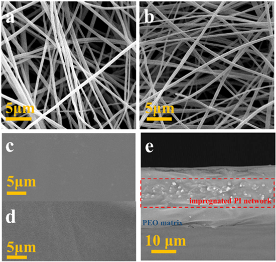
Figure 2. SEM images of (a) PAA nanofiber, (b) PI nanofiber, the upper (c) and lower (d) surfaces of the PI/PEO/LiTFSI CPE and (e) the cross-section of the PI/PEO/LiTFSI CPE.
Download figure:
Standard image High-resolution imageThe thermal stability of electrolytes has a remarkable effect on high-energy solid-state batteries. A comparative experiment was carried out for PEO/LiTFSI SPE and PI/PEO/LiTFSI CPE, and the changes of the two electrolytes are obtained by heating 30 min at 60 °C, 90 °C, 120 °C, 150 °C, and 180 °C, respectively (figure 3). The PEO/LiTFSI SPE changes from white to transparent and the phenomenon of contracting and melting appears at 120 °C. When heated to 180 °C, the electrolyte cannot maintain its initial shape. At the same time, no shrinkage and crack are observed in the PI/PEO/LiTFSI CPE due to the support of the PI nanofiber membrane. It shows that the existence of the PI nanofiber membrane can improve the thermal stability of electrolytes and eliminate the risk of the short circuits during battery cycling. Stress–strain curves of PI/PEO/LiTFSI CPE and PEO/LiTFSI SPE at room temperature are plotted in figure 4. The tensile strength of PI/PEO/LiTFSI CPE is 2.1 MPa with an elongation-at-break of 44%, and it is many times of PEO/LiTFSI SPE (only 0.15 MPa). Therefore, PI/PEO/LiTFSI CPE not only shows good thermal stability but also shows excellent mechanical property, making it a potential candidate for the next generation solid-state lithium batteries.
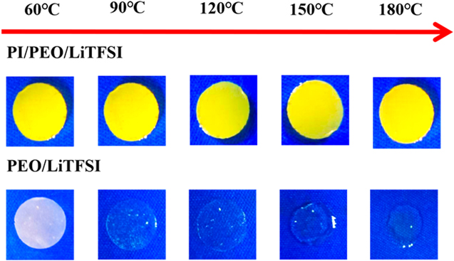
Figure 3. Comparison of the thermal stability between the PI/PEO/LiTFSI CPE and the PEO/LiTFSI SPE.
Download figure:
Standard image High-resolution image
Figure 4. Strain–stress curves of the PI/PEO/LiTFSI membranes and PEO/LiTFSI membranes. Inset: Photo images of mechanical properties of PI/PEO/LiTFSI CPE.
Download figure:
Standard image High-resolution imageIonic conductivity is an important parameter to measure electrolytes. The electrochemical impedance curves of the PI/PEO/LiTFSI CPE at different temperatures are shown in figure 5(a). The impedance of the electrolyte decreases with the increase of temperature due to the movement of polymer segments in the electrolyte membrane increasing with higher temperatures [36]. The ionic conductivities of the PI/PEO/LiTFSI CPE and the PEO/LiTFSI SPE are shown in figure 5(b).
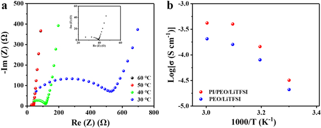
Figure 5. Different temperature-dependent electrochemical impedance spectroscopy plots of PI/PEO/LiTFSI CPE. (a) Arrhenius ionic conductivity (σ) plots of PEO/LiTFSI SPE and PEO/LiTFSI within PI/PEO/LiTFSI CPE (b).
Download figure:
Standard image High-resolution imageCompared with the PEO/LiTFSI SPE, the ionic conductivity of the PI/PEO/LiTFSI CPE is significantly enhanced by the addition of the PI nanofiber network. The ionic conductivity of PI/PEO/LiTFSI CPE is 4.2 × 10⁻⁴ S cm−1 at 60 °C, which is a fold higher than that of the PEO/LiTFSI. The activation energies of the two electrolytes are calculated as 0.34 eV (PEO/LiTFSI SPE) and 0.25 eV (PI/PEO/LiTFSI CPE) by the Arrhenius equation, and it further proves that the PI nanofiber network plays an important role in improving the lithium-ion conductivity of electrolytes. The addition of the PI nanofiber membrane to the electrolyte has many advantages. Firstly, the addition of PI nanofiber as a filler to PEO/LiTFSI can reduce the crystallinity of the polymer and produce flexible local chains in the amorphous phase of the polymer, thus improving the ionic conductivity [37]. Secondly, the network structure of the PI nanofiber membrane prepared by electrospinning not only provides good support for electrolyte but also further gives more transport channels of lithium-ions [38]. Therefore, compared with the PEO/LiTFSI SPE, which could only transport Lithium-ions through the polymer matrix, PI/PEO/LiTFSI CPE can supply more pathways to conduct lithium ions faster for higher lithium-ion conductivity. Finally, the oxygen functional groups in the PI structure have a good affinity for Lithium-ions, so it could promote lithium salt dissociation and improve the ionic conductivity. The above three points can explain the reason for the increase in ionic conductivity of PI/PEO/LiTFSI CPE. For comparison, the electrochemical impedance curves of SPEs filled with PI nanoparticles at different temperatures are also collected and shown in figure S3. The ionic conductivity of the electrolyte filled with PI nanoparticles is lower than that of the PI nanofiber network [39]. The lithium-ion transport pathways of electrolytes with two different morphological fillers are shown in figure S1 (available online at stacks.iop.org/NANO/32/495401/mmedia).
A wide electrochemical window is an important index to determine the application of SPEs in batteries and realize the high voltage of the solid-state batteries. The electrochemical windows of the PI/PEO/LiTFSI CPE and PEO/LiTFSI SPE are obtained by the LSV test and shown in figure 6. The PEO/LiTFSI SPE basically maintains a stable voltage below 5 V versus Li/Li+. By contrast, the electrochemical window of the PI/PEO/LiTFSI CPE expands to 5.4 V versus Li/Li+, suggested that the PI nanofiber membrane plays an important role in improving the electrochemical stability of SPE realizing high voltage lithium-ion batteries. The electrochemical window of PI nanoparticles/PEO/LiTFSI CPE is shown in figure S4. The electrochemical window of the PI nanoparticles/PEO/LiTFSI CPE is 5.2 V. Therefore, it further proves that the PI nanofiber network is a good electrolyte filler, and the electrochemical performance of the electrolyte with PI nanofiber network would be further evaluated.

Figure 6. Linear sweep voltammetry (LSV) curves of the PI/PEO/LiTFSI CPE and the PEO/LiTFSI SPE.
Download figure:
Standard image High-resolution imageTo test the stability of the PI/PEO/LiTFSI CPE with Li metal anode, the cycling test of Li/CPE/Li symmetric cells was carried out. Figure 7(a) shows the time-dependent voltage profile of the symmetric cells. The symmetric Li cell with PI/PEO/LiTFSI CPE cycles stably after 900 h at 60 °C with a current density of 0.1 mA cm−2. After the first 40 h of cycling, the voltage drops slightly from 0.45 to 0.35 V, and then the voltage of the cell stabilizes at 0.35 V. The main reason for the slight decrease of voltage is that the interface contact between the lithium metal and the electrolyte membrane becomes better during the cycling at 60 °C so that the interface impedance decreases. This behavior can be further proved by the EIS spectra of the symmetrical battery shown in figure 7(b). In comparison, the symmetric Li cell of PEO/LiTFSI SPE appears to short-circuit after cycling of 120 h. The local magnification of the cycle curve (after 120 h) of the symmetric battery with PEO/LiTFSI SPE is shown in figure S5. Therefore, the addition of PI nanofiber membrane not only improves the mechanical properties of electrolytes, but also effectively inhibits the uneven deposition of metal Li and the formation of Li dendrites, which can effectively prevent the battery from short circuit and achieve a longer cycle life [40].

Figure 7. Comparison of long-term cycling of symmetrical Li cells with PEO/LiTFSI SPE and PI/PEO/LiTFSI CPE. Inset: voltage profile of Li/PI/PEO/LiTFSI/Li at the 100th, 250th and 400th cycle respectively (a), Impedance spectra of the PI/PEO/LiTFSI CPE before and after cycling (b), Magnified EIS spectra in the high-frequency region (c).
Download figure:
Standard image High-resolution imageThe PI/PEO/LiTFSI CPE maintains good chemical stability, and it is feasible to apply it for solid-state battery. We used PI/PEO/LiTFSI CPE and PEO/LiTFSI SPE to assemble LiFePO4ǀLi solid-state batteries. The initial discharge capacity of the cell with PI/PEO/LiTFSI CPE is as high as 158 mAh g−1 at 0.4 C, and the coulombic efficiency is always maintained at 99% (figure 8(a)), which also indicates that the interface between the electrolyte and metal Li is stable during the cycling [41]. At the same time, the discharge capacity of the cell with PEO/LiTFSI SPE shows a trend of rapid decline, and the capacity of the cell with PEO/LiTFSI SPE is significantly lower than that of the cell with PI/PEO/LiTFSI CPE. After 55 cycles, the capacity of the cell with PEO/LiTFSI SPE decreases to 75 mAh g−1 and then the battery is short-circuited. Besides, the columbic efficiency of the cell with PEO/LiTFSI SPE is extremely unstable during the cycling. The cycle performance of the cells at different rates from 0.4 C to 1 C at 60 °C is shown in figure 8(b). The discharge of capacity of the cell with PEO/LiTFSI SPE is lower than that of the cell with PI/PEO/LiTFSI CPE at the same rate, especially at the high rate of 0.8 C and 1 C. The discharge capacities of the cell with PI/PEO/LiTFSI CPE at rate 0.4 C, 0.6 C, 0.8 C, and 1 C are 158, 155, 149, and 128 mA h g−1, respectively. When the rate of the battery turns back from 1 C to 0.4 C, the discharge capacity is still as high as 149 mAh g−1. This is attributed to the good stability and high ionic conductivity of electrolytes and the good interfacial properties between PI/PEO/LiTFSI CPE and Li-metal anode [42]. The voltage profiles of the cell with PI/PEO/LiTFSI CPE at different rates are shown in figure 8(c), which also shows good electrochemical reversibility of the battery. The above results suggest that the addition of PI nanofiber into electrolyte can greatly improve the cycle stability and enhance the rate performance, which is believed to be a progressive strategy in solid-state battery.

Figure 8. (a) Comparison of cycling performance and coulombic efficiency of the Li/LFP cell with the PI/PEO/LiTFSI CPE and PEO/LiTFSI SPE, (b) rate capabilities at 0.4 C, 0.6 C, 0.8 C and 1 C, (c) Charge/discharge curves of the Li/LFP cell with the PI/PEO/LiTFSI CPE at various rates.
Download figure:
Standard image High-resolution image
4. Conclusion
In summary, the PI/PEO/LiTFSI CPE with good flexibility, strong mechanical strength, and high-temperature resistance is successfully prepared in this work. The continuous PI nanofiber network can provide a long-range and continuous transport channel for lithium-ions, and the ionic conductivity of the electrolyte is as high as 4.2 × 10⁻⁴ S cm−1 at 60 °C. In addition, the PI/PEO/LiTFSI CPE shows a wide electrochemical window up to 5.4 V versus Li/Li+. Furthermore, compared with the traditional PEO/LiTFSI electrolyte, PI/PEO/LiTFSI CPE have a good contact surface with lithium metal and excellent mechanical property, which can inhibit the dendrite growth of Li and enable the symmetrical cell to stably for more than 900 h. More importantly, compared with PEO/LiTFSI SPE, PI/PEO/LiTFSI CPE shows excellent cycle stability and superior rate performance in LiFePO4ǀLi solid-state battery. Thus, the PI nanofiber network-reinforced CPE have good flexibility, strong mechanical property, and a series of excellent electrochemical properties, making it promising for the applications in solid-state batteries.
Acknowledgments
This work was financially supported by National Key R&D Program of China (Grant No. 2018YFB0104300), National Natural Science Foundation of China (NSFC-51707151), National Natural Science Foundation of China (Grant No. 51772241), and Natural Science Foundation of Jiangsu Province (Grant No. BK20190222). X Han would like to thank the Independent Research Project of State Key Laboratory of Electrical Insulation and Power Equipment (Grant No. EIPE19111) for the financial support. F Shen and B Zhao acknowledge the State Key Laboratory of Electrical Insulation and Power Equipment for financial support.
Data availability statement
All data that support the findings of this study are included within the article (and any supplementary files).
Ethical statement
Ethics approval was not required for this research.