

Abstract
Transition metal sulfide nanostructure composites have received significant attention as energy conversion and storage devices. In this work, we report a three-dimension (3D) nanostructure with the Ni9S8 nanorods embedded in oxygen-incorporated MoS2 (O-MoS2) nanosheets for supercapacitors and hydrogen evolution catalysts. The in situ grown Ni9S8/O-MoS2 nanocomposite on carbon cloth can be used as a free binder supercapacitor electrode and hydrogen evolution catalyst. The Ni9S8/O-MoS2 nanocomposite exhibits electrochemical behaviors with a specific capacitance of 907 F g−1 (at 2 A g−1) and good cycle stability after 1200 cycles due to its unique mutual embedding 3D nanostructure. Furthermore, the Ni9S8/O-MoS2 nanocomposite also shows highly electrocatalytic features for hydrogen production with an onset overpotential of ∼150 mV and a low Tafel slope of ∼81 mV dec−1. The oxygen incorporation of MoS2 provides more active sites to participate in the catalytic process for the hydrogen evolution reaction.
Export citation and abstract BibTeX RIS
1. Introduction
Nowadays, increasing energy consumption and ever-growing environmental pollution are a major challenge to humans. Exploring sustainable energy and developing green energy storage devices are urgent. Among the sustainable green energies, hydrogen (H2) is regarded as a candidated energy carrier of the future [1, 2]. In particular, sustainable hydrogen production from water splitting has drawn more and more attention [3–5]. As for energy storage devices, supercapacitors have been considered as a potential candidate for green energy storage with a rapid charging–discharging rate, high power density, and long cycling performance [6–8]. Whether as a catalyst for hydrogen evolution reaction (HER) or as an electrode used as a supercapacitor, an appropriate active material is vital.
Transition metal oxides/hydroxides as the active materials of supercapacitor electrodes have been extensively surveyed in the past few years [9–12]. However, the poor conductivity and low cycling stability of transition metal oxides/hydroxides have hindered their practical application in energy devices. Therefore, it is desirable to explore new active materials so as to further enhance the properties of supercapacitors. Owing to their good conductivity and high oxidation–reduction ability, transition metal sulfides have become the promising active material for supercapacitor electrodes [13, 14]. Meanwhile, sulfide can withstand an acidic environment during a continuous HER, which is where oxides cannot be used.
The groups of Zhang [15], Lou [16], Liu [17], and Wang [18] synthesized various nanostructured nickel sulfides, and used them as high-performance supercapacitor electrodes. Sun's group [19] reported three-phase nickel sulfides nanostructures for an electrocatalytic producing hydrogen from water splitting in alkaline solutions; they all exhibited good performance for electrocatalytic HERs. The groups of Zhu [20], Xie [21], Gupta [22], and Lou [23] fabricated nanostructured cobalt sulfide hybrid electrodes, exhibiting high specific capacitance and superior rate capability. The groups of Yan [24] and Therese [25] synthesized MoS2 nanostructure supercapacitor electrodes and obtained large specific capacitance and good cycling stability. Chhowalla's group [26] and Khalil et al [27] reported conducting MoS2 nanosheets that showed catalytic activity for hydrogen evolution. Liu et al [28] have used MoS2 ultrathin nanosheets to decorate reduced graphene oxide for improving the electrocatalytic activity of hydrogen evolution.
Transition metal dichalcogenides, such as MoS2, Ni3S2 and CoS [29–32], can be used as electrode materials and exhibit excellent electrochemical properties for supercapacitor applications. Transition metal sulfides can also show certain hydrogen evolution behaviors. Is it possible to have a kind of composite sulfide with a special nanostructure, which can not only show good electrochemical performance for supercapacitor application, but also exhibit notable electrocatalytic activity for HER applications?
In this work, taking advantage of the well-defined electrochemical activity of MoS2 and high cycle stability of nickel sulfide, we fabricated a novel three-dimensional (3D) nanostructure with Ni9S8 nanorods embedded in oxygen-incorporated MoS2 (O-MoS2) nanosheets using one-step hydrothermal synthesis. The Ni9S8/O-MoS2 nanocomposite was grown in situ on carbon cloth and serves as a free binder electrode for supercapacitor and hydrogen evolution. It showed electrochemical properties with a specific capacitance of ∼907 F g−1 at 2 A g−1 and capacitance retention of ∼85.7% after 1200 cycles. What is more, the Ni9S8/O-MoS2 nanocomposite exhibited electrocatalytic activity toward hydrogen produced with small onset overpotential. The resulting performance predicted that the bifunctional materials of Ni9S8/O-MoS2 nanocomposite have potential applications for energy storage and hydrogen evolution.
2. Experimental
2.1. Synthesis of materials
Sodium molybdate (Na2MoO4·2H2O), thiourea (CH4N2S), nickel nitrate (Ni(NO3)2·6H2O) and other chemicals are commercial analytical reagents. Carbon cloth substrate was pretreated through acid solution, and then it was successively cleaned using ethanol, acetone and deionized (DI) water with the aid of ultrasonic treatment several times before the hydrothermal reaction.
In the reaction, 0.6 g of Na2MoO4·2H2O, 0.727 g of Ni(NO3)2·6H2O and 1.2 g of CH4N2S were dissolved in the mixture with 15 ml of ethanol and 45 ml of DI water. A synthesis schematic diagram is shown in figure 1. After it is fully dissolved, the mixed solution was put in a 100 ml Teflon-lined autoclave, and then the pretreated carbon cloth (1 × 1 cm) was placed into the autoclave and used as the substrate for the growth of the nanostructure. Then the autoclave was kept at 160 °C for 22 h in an oven. After naturally cooling down, the carbon cloth was taken out and washed with DI water, then dried in a nitrogen atmosphere. The loading amount of electrode materials on the carbon cloth for MoS2 and Ni9S8/O-MoS2 was around 0.32 and 0.40 mg cm−2, respectively.

Figure 1. A schematic diagram of the nanocomposite synthesis.
Download figure:
Standard image High-resolution image2.2. Material characterization
The crystal structures of the nanomaterial were surveyed by x-ray diffraction (XRD, Bruker Axs, D8 Advance) with Cu Kα radiation (λ = 0.154 06 nm). The chemical compositions of the composites were studied using x-ray photoelectron spectroscopy (XPS, ESCLAB 250Xi). Energy-dispersive x-ray spectroscopy (EDS) was also utilized to investigate the element distribution of the nanocomposites. The morphologies were studied using scanning electron microscopy (SEM, Hitachi S-4800) and high resolution transmission electron microscopy (HRTEM, FEI Tecnai G20).
2.3. Electrochemical measurements
2.3.1. Supercapacitors
The electrochemical measurements were performed in 1 M KOH electrolyte solution with a three-electrode testing system (CHI 660E electrochemical workstation). The synthesized Ni9S8/O-MoS2 nanocomposite and pure MoS2 on the carbon cloth directly served as the free binder work electrodes. Pt foil was the counter electrode, and a saturated calomel electrode (SCE) acted as the reference electrode. Electrochemical impedance spectroscopy tests (EIS) are measured over the frequency range from 10−2 to 106 Hz. The potential window range for the cyclic voltammetry (CV) test is from −0.3 to 0.6 V.
2.4. Hydrogen evolution reaction
The electrocatalytic characterizations of HER activity were executed on an electrochemical workstation (CHI 660E electrochemical workstation) with a graphite rod as the counter electrode and a Ag/AgCl electrode as the reference electrode. The measured potentials were referred to reversible hydrogen electrode (RHE) using the following expression: ERHE = EAg/AgCl + 0.059 pH + 0.1988. Linear sweep voltammetry measurements were conducted at a scan rate of 5 mV s−1 in a 0.5 M H2SO4 electrolyte.
3. Results and discussion
The XRD patterns of pure MoS2 and the Ni9S8/O-MoS2 nanocomposite are studied (figure S1 in supporting information is available online at stacks.iop.org/NANO/28/445407/mmedia). For the pure MoS2, there are diffraction peaks at 33.0° and 58.3°, which corresponds to the (101) and (110) planes of MoS2, respectively (JCPDS No. 17-0744). In the XRD pattern of the Ni9S8/O-MoS2 nanocomposite, there are other diffraction peaks besides the MoS2 phase. The week diffraction peaks around 22.1°, 24.3°, 27.2°, 40.5°, 42.4° and 46.5° can be assigned to the (112), (002), (202), (114), (332), and (422) planes of Ni9S8, respectively (JCPDS No. 22-1193).
The compositions and chemical states of MoS2 and Ni9S8/O-MoS2 were investigated using XPS spectra. As shown in figure S2(a), the full XPS spectrum of MoS2 suggests that the composite contains Mo and S (supporting information). Figures S2(b) and (c) show the XPS spectra of Mo 3d and S 2p, respectively. The peaks of 232.1 and 228.9 eV are known as Mo 3d3/2 and Mo 3d5/2, which are the characteristic of Mo4+ in MoS2. The S 2 s peak at 226.1 eV in the Mo 3d spectrum is also a typical feature of MoS2 [33]. The S 2p spectrum can be fitted by Gaussian–Lorentzian curves with the peaks located at 161.9 and 162.8 eV. The binding energies at 161.9 and 162.8 eV correspond to S 2p3/2 and S 2p1/2, respectively, which are attributed to the S2− states in MoS2 [34].
The survey scan XPS spectra of Ni9S8/O-MoS2 indicate the coexistence of Mo, Ni, S, and O elements in the nanocomposite, as shown in figure 2(a). The Mo 3d spectrum can be decomposed into two spin–orbit pairs. As shown in figure 2(b), the peaks at 232.2 and 228.9 eV correspond to Mo4+ 3d3/2 and Mo4+ 3d5/2, respectively. The weak peaks at 236.6 and 233.5 eV belong to Mo6+ 3d3/2 and Mo6+ 3d5/2, respectively, which reveal that there is oxygen-incorporated MoS2 in the nanocomposite [35]. In figure 2(c), the Ni 2p XPS spectrum is featured with peaks at 874.8 and 857.0 eV, ascribed to Ni 2p1/2 and Ni 2p3/2, respectively. In the S 2p spectrum (figure 2(d)), there are two prominent peaks around 166.5 and 162.1 eV, which are a typical feature of S2− in the product. What is more, the broad peak at 168.7 eV is related to SO42− species formed in aqueous solution [36]. The peak located at 532.1 eV in the O 1 s spectrum (figure 2(e)) could be associated with the incorporation of oxygen into MoS2 [37]. Compared with pure MoS2, oxygen-incorporated MoS2 is involved in the Ni9S8/O-MoS2 nanocomposite during one-step hydrothermal synthesis. The surplus S source in the synthesis of pure MoS2 inhibits the incorporation of oxygen. To obtain the Ni9S8/O-MoS2 nanocomposite, the introduction of a Ni source easily leads to water splitting in the mixed solution, and then oxygen incorporation also occurs during this process.
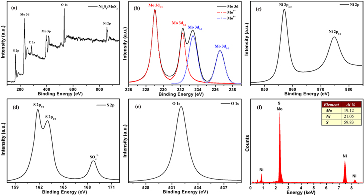
Figure 2. (a) The XPS spectra of Ni9S8/O-MoS2. The XPS spectra of Mo 3d (b), Ni 2p (c), S 2p (d), and O 1 s (e). (f) The EDS analysis of the Ni9S8/O-MoS2 nanocomposite.
Download figure:
Standard image High-resolution imageIn addition, EDS analysis was performed to characterize the elemental composition of the Ni9S8/O-MoS2 nanocomposite, as shown in figure 2(f), which also verifies the presence of the elements of Mo, Ni and S. These contents are presented in the inset of figure 2(f), which closely equal the atomic ratio of Ni9S8 and MoS2. The composition of the Ni9S8/O-MoS2 nanocomposite is consistent with XRD measurements. These results confirm the formation of the Ni9S8/O-MoS2 nanocomposite. Furthermore, the elemental mappings confirm the highly uniform distribution of the Mo, Ni, and S in the Ni9S8/O-MoS2 nanocomposite, as displayed in figure S3.
The SEM morphologies of MoS2 and Ni9S8/O-MoS2 nanocomposite are exhibited in figure 3. The pure MoS2 appears spherical in shape with irregular surfaces at low magnification in figure 3(a). With a further increase in magnification, it can be seen that the MoS2 nanostructure is composed of nanosheets (figures 3(b) and (c)). For comparison, Ni9S8 nanorods were prepared under the same conditions. Ni9S8 nanorods are dense and homogeneous on carbon cloth, and have a diameter of 50–150 nm and a length of 1–5 μm (as shown in figure 3(d)). More SEM morphologies and structure analyses of Ni9S8 nanorods are provided in figure S4. As seen from figures 3(e) and (f), the Ni9S8/O-MoS2 nanocomposite exhibits a novel 3D nanostructure with the Ni9S8 nanorods embedded in MoS2 nanosheets. Such a novel 3D nanostructure implies that there may be excellent electrochemical performance for the Ni9S8/O-MoS2 nanocomposite.

Figure 3. (a), (b) and (c) are SEM morphologies of MoS2 at different magnifications. (d) SEM image of Ni9S8 nanorods. (e) and (f) SEM images of the Ni9S8/O-MoS2 nanocomposite.
Download figure:
Standard image High-resolution imageFigures 4(a) and (b) provide typical TEM images of the Ni9S8/MoS2 nanocomposite, showing the typical nanosheet and nanorod morphology of MoS2 and Ni9S8. In figure 4(c), the HRTEM image exhibits a well-arrayed (112) plane of Ni9S8 with a plane distance of 4.03 Å. The corresponding selected area electron diffraction (SAED) pattern (the inset of figure 4(c)) shows hexagonally arranged bright spots, indicating the high crystallinity of the Ni9S8 nanorods. The HRTEM image of the MoS2 nanosheet (figure 4(d)) shows fringes with lattice spacing of 2.69 Å, which corresponds to the (101) plane of MoS2. The corresponding SAED pattern in the inset of figure 4(d) is characterized with diffraction rings, revealing the polycrystalline nature of MoS2 nanosheets.
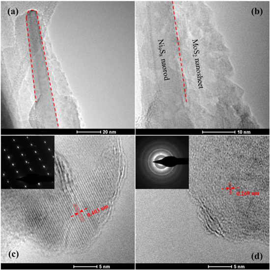
Figure 4. (a) and (b) Typical TEM images of the Ni9S8/MoS2 nanocomposite. (c) HRTEM image of the Ni9S8 nanorod, the inset is the SAED pattern of the Ni9S8 nanorod. (d) HRTEM image of the MoS2 nanosheet, the inset is the corresponding SAED pattern.
Download figure:
Standard image High-resolution imageThe obtained nanocomposites grown in situ on carbon cloth can be used as a binder-free supercapacitor electrode. CV tests were performed to investigate the electrochemical performance of MoS2 and the Ni9S8/O-MoS2 nanocomposite. Figure 5(a) shows the CV curves of pure MoS2 and the Ni9S8/O-MoS2 nanocomposite at a scan rate of 10 mV s−1. Both the CV curves exhibit a larger potential range of −0.3–0.6 V. There are well-defined redox peaks corresponding to the reversible faradaic reactions of Ni ions and Mo ions, which can be clearly observed in the CV curves, suggesting their excellent pseudocapacitive characteristics.

Figure 5. (a) The CV curves of pure MoS2 and the Ni9S8/O-MoS2 nanocomposite at a scan rate of 10 mV s−1. (b) The CV curves of the Ni9S8/O-MoS2 nanocomposite at various scan rates.
Download figure:
Standard image High-resolution imageObviously, the Ni9S8/O-MoS2 nanocomposite occupies a larger enveloped area than pure MoS2, attributable to the strong chemical and electrical synergistic effects of the electronically conductive Ni9S8 with the redox-active MoS2 on the surface redox charge-transfer mechanism. Moreover, due to high-exposed redox-active sites of the mutual embedded 3D nanostructure of the Ni9S8/O-MoS2 nanocomposite, it offers a large number of accessible active sites for protons. This indicates that the Ni9S8/O-MoS2 nanocomposite has better electrochemical properties.
Figure 5(b) shows CV curves of the Ni9S8/O-MoS2 nanocomposite with disparate scan rates from 2 to 200 mV s−1. All curves exhibit the redox peaks and a similar shape. These phenomena suggest the presence of reversible Faradic reaction and typical pseudocapacitive characteristics. The redox peaks for Ni9S8/O-MoS2 nanocomposite are associated with the reversible faradaic reactions of Ni ions and Mo ions at the surface-exposed edges. The faradaic reaction occurs through the injection of protons into the redox-active sites of the Ni9S8/O-MoS2 that can recombine with electrons to produce the reduction peaks seen in the CV curves. There are two possible charge-storage mechanisms of Ni9S8/O-MoS2 associated with well-defined redox peaks: (i) proton insertion/desertion into the MoS2 interlayers; (ii) the redox deposition of protons on the intralayer surface of the MoS2 nanosheets and Ni9S8 nanorods. The detailed reversible reactions are summarized as follows:


and

To assess the prospect of the Ni9S8/O-MoS2 nanocomposite as an active material for a supercapacitor electrode, galvanostatic charging–discharging tests were executed. Figure 6(a) shows the galvanostatic charging–discharging curves with different current densities. All curves display nonlinear profiles, and further confirm the faradaic behavior, which is in accordance with the CV measurements. These curves are nearly symmetric at different current densities, implying good reversibility according to the faradaic redox reactions. Figure 6(b) presents the charging–discharging curves of MoS2 and the Ni9S8/O-MoS2 nanocomposite measured at the current density of 2 A g−1. It can be seen that both charging–discharging curves display prominent pseudocapacitive characteristics, agreeing with the CV results. It is obvious that the discharging time of the Ni9S8/O-MoS2 nanocomposite electrode is much longer than that of the MoS2 electrode.

Figure 6. (a) The galvanostatic charging–discharging curves of the Ni9S8/O-MoS2 nanocomposite at different current densities. (b) The charging–discharging curves of MoS2 and the Ni9S8/O-MoS2 nanocomposite measured at the current density of 2 A g−1.
Download figure:
Standard image High-resolution imageThe specific capacitance (C) can be obtained from the galvanostatic charging–discharging curves based on the formula:

where I represents the constant discharging current (A), m corresponds to the mass of electrode materials (g), Δt is the discharging time (s), and ΔV represents the potential range (V). The specific capacitance is obtained from the discharging curve at various current densities, as shown in figure 7(a).
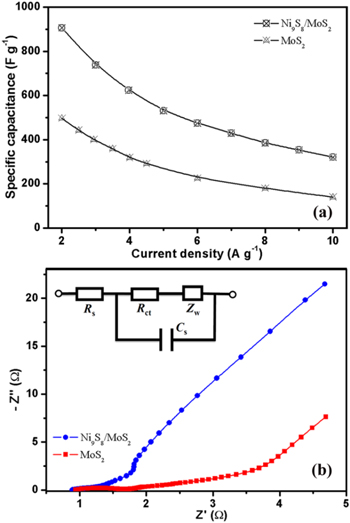
Figure 7. (a) The specific capacitances of the Ni9S8/O-MoS2 nanocomposite electrode and the MoS2 electrode obtained from the discharging curves. (b) EIS plots of MoS2 and the Ni9S8/O-MoS2 nanocomposite, the top left inset is an equivalent circuit model for the fitting of the EIS data.
Download figure:
Standard image High-resolution imageNi9S8/O-MoS2 nanocomposite electrodes delivered high capacitance of 907, 738, 531, 475, and 430 F g−1 at various current densities of 2, 3, 5, 6, and 7 A g−1, respectively, which is obviously higher than the MoS2 electrode. The capacitance values of MoS2, Ni9S8 and the Ni9S8/MoS2 nanocomposite were calculated from CV curves under different scan rates and are shown in figure S5. The introduction of Ni9S8 nanorods and the mutual embedding 3D nanostructure significantly enhances the electrochemical performance of MoS2. The enhancement of the capacitive performance of the Ni9S8/O-MoS2 nanocomposite electrode is attributable to the good electrical conductivity of Ni9S8 nanorods and the high porosity of mutual embedding 3D nanostructures. Ni9S8 nanorods act as a conducting channel for electrons in the nanocomposite, then enhance the fast transfer of electrons in the whole electrode. Eventually, the Ni9S8/O-MoS2 hybrid nanostructure achieves higher electrochemical performance.
Figure 7(b) displays the Nyquist plots of EIS for MoS2 and Ni9S8/O-MoS2 electrodes. The plots are composed of an arc in the high-frequency range and a straight line in the middle and low frequency range. The inset of figure 7(b) shows the equivalent circuit model for fitting EIS data, which is composed of the interfacial charge-transfer resistance (Rct), the series resistance (Rs), the diffusion Warburg impedance (Zw), and the faradaic pseudocapacitor (Cs). The intersection of the curve on the real axis at the high-frequency range represents the equivalent series resistance (Rs), and the diameter of the semicircular arc expresses the interfacial charge-transfer resistance (Rct) at the contact interfaces. It can be seen that the series resistance (Rs) of MoS2 and Ni9S8/O-MoS2 electrodes are 0.95 and 0.88 Ω, respectively, which indicate the higher conductivity of Ni9S8/O-MoS2. The Ni9S8/O-MoS2 electrode obviously shows a semicircular arc with much smaller diameter in the high-frequency region than the MoS2 electrode, indicating its lower charge-transfer resistance. The charge-transfer resistance (Rct) was calculated by fitting the equivalent circuit and was found to be 1.31 Ω for the Ni9S8/O-MoS2 electrode and 1.52 Ω for the MoS2 electrode. The lower charge-transfer resistance in Ni9S8/O-MoS2 is attributable to the enhancement of the conductivity with the introduction of nickel ions, and it suggests the better electrochemical performance of the Ni9S8/O-MoS2 electrode for supercapacitor applications.
The long-term cycling stability is investigated via charging–discharging measurements at the current density of 2 A g−1 for 1200 cycles. Figure S6 reveals the specific capacitance retention for various cycle numbers, it reveals good stability of the Ni9S8/O-MoS2 nanocomposite in the total cycles. The Ni9S8/O-MoS2 nanostructure electrode possesses capacitance retention of 85.7% after 1200 cycles, which indicates the good cycle stability of nanocomposite electrode.
Several excellent areas of performance of the Ni9S8/O-MoS2 nanocomposite make it a potential electrode material for supercapacitors, and these can be rationalized as follows. (i) The combination of MoS2 and Ni9S8 has taken advantage of the pseudocapacitance from MoS2 and Ni9S8, creating a strong synergistic effect of individual compositions. (ii) The 3D nanostructure with the Ni9S8 nanorods embedded in MoS2 nanosheets has plenty of active sites, which prompts the redox reaction between the electrolyte and the electrode materials becoming more efficient. (iii) The void space between MoS2 nanosheets in 3D nanostructure can buffer the volume change originating from the ion transport during the charging–discharging process. (iv) In such a mutual embedding 3D nanostructure, Ni9S8 nanorods also act as the conducting channels for the fast transportation of electrons. (v) The obtained nanocomposite grown in situ on carbon cloth can serve as a free binder supercapacitor electrode, which promotes an effective electrochemical reaction. Due to such a design, the Ni9S8/O-MoS2 nanocomposite has more active sites, fast ions and electron transport, and improved electrochemical reaction, and has potential applications in supercapacitors.
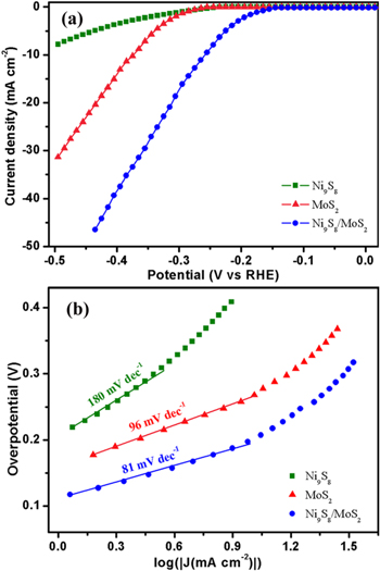
To evaluate the electrocatalytic performance in the HER, the as-grown active materials are examined in a three-electrode system. Figure 8(a) shows the polarization curves of Ni9S8, MoS2 and the Ni9S8/O-MoS2 nanocomposite. It is obvious that the Ni9S8/O-MoS2 nanocomposite demonstrates a low overpotential ∼150 mV, while MoS2 exhibits an overpotential of 230 mV. The cathodic current rises rapidly with the increase in negative potential for MoS2 and Ni9S8/O-MoS2. What is more, Ni9S8/O-MoS2 nanocomposite exhibits a large cathodic current density of 38.3 mA cm−2 with the overpotential of 400 mV, which is higher than that of MoS2 (13.8 mA cm−2). Ni9S8 displays an overpotential of 210 mV, but the response of the cathodic current to negative potentials is too slow.
Figure 8. (a) The polarization curves and (b) the corresponding Tafel plots of Ni9S8, MoS2 and the Ni9S8/O-MoS2 nanocomposite.
Download figure:
Standard image High-resolution image
Such excellent HER characteristics of the Ni9S8/O-MoS2 nanocomposite catalysts could result from the following points. First, oxygen incorporation increases the defect and surface atomic ratio, giving more active sites to participate in the catalytic process [38]. Second, the introduction of nickel ions can enhance the conductivity and active sites of the catalyst; it also prevents the stacking of MoS2 nanosheets. The analysis of EIS exhibits the enhanced conductive behavior of Ni9S8/O-MoS2 compared with MoS2. Third, in situ synthesis of Ni9S8/O-MoS2 nanocomposite through a hydrothermal method results in a pronounced synergetic effect between Ni9S8 nanorods and MoS2 nanosheets. The combination of MoS2 nanosheets and Ni9S8 nanorods with a mutual embedding 3D nanostructure has obviously magnified their own electrocatalytic properties.
The Tafel slope gives an additional insight into the HER mechanism. The HER is an intricate electrochemical reaction occurring on the surface of a catalyst [39]. The Volmer–Heyrovsky process and the Volmer–Tafel pathways [40, 41] are two generally accepted HER mechanisms for reducing H+ to H2 in an acidic electrolyte.
Volmer–Heyrovsky process:
H3O+ + e− + Δ → Δ-H* + H2O

Volmer–Tafel pathways: H3O+ + e− + Δ → Δ-H* + H2O
where Δ represents an active site of the catalyst, and Δ-H* represents a hydrogen atom adsorbed at the active site.
The Tafel slope is normally derived from the polarization curve, which is an important parameter of chemical activity. The linear region of the corresponding Tafel plots is fitted by the Tafel expression [42]. Figure 8(b) shows the Tafel plots of Ni9S8, MoS2 and the Ni9S8/O-MoS2 nanocomposite. By extrapolating the Tafel plot to an overpotential of 0 V, the exchange current density can be extracted. It is found that the MoS2 exhibits a Tafel slope of 96 mV dec−1 and an exchange current density of 0.118 mA cm−2. The Ni9S8 is not significantly active for the HER, displaying a Tafel slope of 180 mV dec−1 and an exchange current density of 0.159 mA cm−2. Tafel analysis of the Ni9S8/O-MoS2 nanocomposite indicates an exchange current density of 0.209 mA cm−2 and a Tafel slope of 81 mV dec−1. On the basis of the Tafel analysis, the turnover frequency (TOF) of the Ni9S8/O-MoS2 nanocomposite is estimated to be 1.51 s−1 at an overpotential of 400 mV, while the calculated TOF for pure MoS2 and Ni9S8 are 0.80 s−1 and 0.62 s−1, respectively. These results explain the better HER catalytic performance of the Ni9S8/O-MoS2 nanocomposite. The larger exchange current density and the relatively low Tafel slope of the Ni9S8/O-MoS2 nanocomposite indicate that it has a larger surface area, faster electron transfer rate, and more favorable HER kinetics.
The long-term catalytic stability of the Ni9S8/O-MoS2 nanocomposite is investigated by the chronoamperometric test at a static overpotential of 300 mV. The Ni9S8/O-MoS2 appears to have excellent stability for the HER, as shown in figure S7, the current density has negligible loss even after 24 h of chronoamperometric measurement.
We deem that the hydrogen generation is mainly on the O-MoS2. According to the results of electrocatalytic performance and specific surface area, O-MoS2 demonstrates a better catalytic activity. Moreover, the electrons transfer from the Ni9S8 nanorods to the MoS2 nanosheets and increase the conductivity of the Ni9S8/O-MoS2 nanocomposite electrocatalyst, enhancing the HER performance. On the other hand, the Ni9S8 nanorods can accelerate the HER kinetic process. The positively charged Ni 2p species have strong electrostatic affinity, which results in H2O molecules preferentially attaching to the Ni9S8 site. Then the nearby MoS2 site would facilitate H+ ions electroreduction [43], imparting synergistic HER catalytic activity to the Ni9S8/O-MoS2 nanocomposite.
4. Conclusion
In summary, we successfully prepared a Ni9S8/O-MoS2 nanocomposite with mutual embedding 3D nanostructure on carbon cloth. The in situ synthesized active materials can serve as a free binder electrode for supercapacitors and HER. As for supercapacitor electrodes, the Ni9S8/O-MoS2 nanocomposite demonstrates a specific capacitance of 907 F g−1 at a scan rate of 2 A g−1 and a stability of 85.7% with continuous cycling, which was attributed to the mutual embedding 3D nanostructure. When used as the catalyst of HER, the Ni9S8/O-MoS2 nanocomposite reveals good HER behaviors with a small onset overpotential, low Tafel slope and high current density. Taken together, this excellent electrochemical behavior and electrocatalysis performance of the Ni9S8/O-MoS2 nanocomposite imply promising bifunctional application in energy storage and hydrogen production.
Acknowledgments
This work was supported by the National High Technology Research and Development Program (Grant No. 2015AA050601), the China Postdoctoral Science Foundation (Grant No. 2015M572193), the National Natural Science Foundation of China (Grant Nos. 11674252, 91433203, and 61376013).